

Page 1

INSTALLATION INSTRUCTIONS
FOR SIERRA GRILLE GUARD KIT #295942 AND
WRAPAROUND KIT #295943
ON 2004-2007 FORD F-150
Notice
Ramsey kits are designed for use with Ramsey Winches only.
Use or sale of kits for other winches or applications voids warranty.
Warning
Ramsey offers mounting kits and winches for various vehicles. In crash tests on a limited number of automotive
manufacturer’s vehicles, winches/mounting kits, which have been properly mounted, have not interfered with air bag
operation.
The user/customer, or their installer, must verify that the mounting kit does not interfere with the factory air bag
sensors, which must not be relocated or modified in any way.
The user/customer should follow the vehicle manufacturer’s recommendations and those of a qualified mechanic to
determine if the winch/mounting kit might interfere with the air bag operation. The user/customer should then
determine the suitability of a winch/mounting kit on a particular vehicle.
PLEASE BE ADVISED THAT THE VEHICLE’S AIR BAG SYSTEM MAY NOT OPERATE PROPERLY IF THE
WINCH/MOUNTING KIT IS NOT INSTALLED IN COMPLIANCE WITH THE VEHICLE MANUFACTURER’S
RECOMMENDATIONS.
DO NOT ATTACH TOW HOOK TO ANY PART OF THE MOUNTING KIT UNLESS INSTRUCTED TO DO SO.
DO NOT SUBSTITUTE ATTACHING HARDWARE ITEMS (BOLTS, NUTS, OR WASHERS).
READ AND UNDERSTAND WINCH OWNER’S MANUAL BEFORE INSTALLATION AND OPERATION OF WINCH.
SEE WARNING AND CAUTIONS IN WINCH OWNER’S MANUAL.
IMPORTANT NOTES!
1. Right and left hand directions as if seated behind steering wheel.
2. All fastening hardware should be loosely assembled until directed to tighten.
RAMSEY WINCH COMPANY
P.O. BOX 581510
TULSA, OKLAHOMA 74158
PHONE: (918) 438-2760 • FAX: (918)438-6888
http://www.ramsey.com
913388-0307-D
Page 2
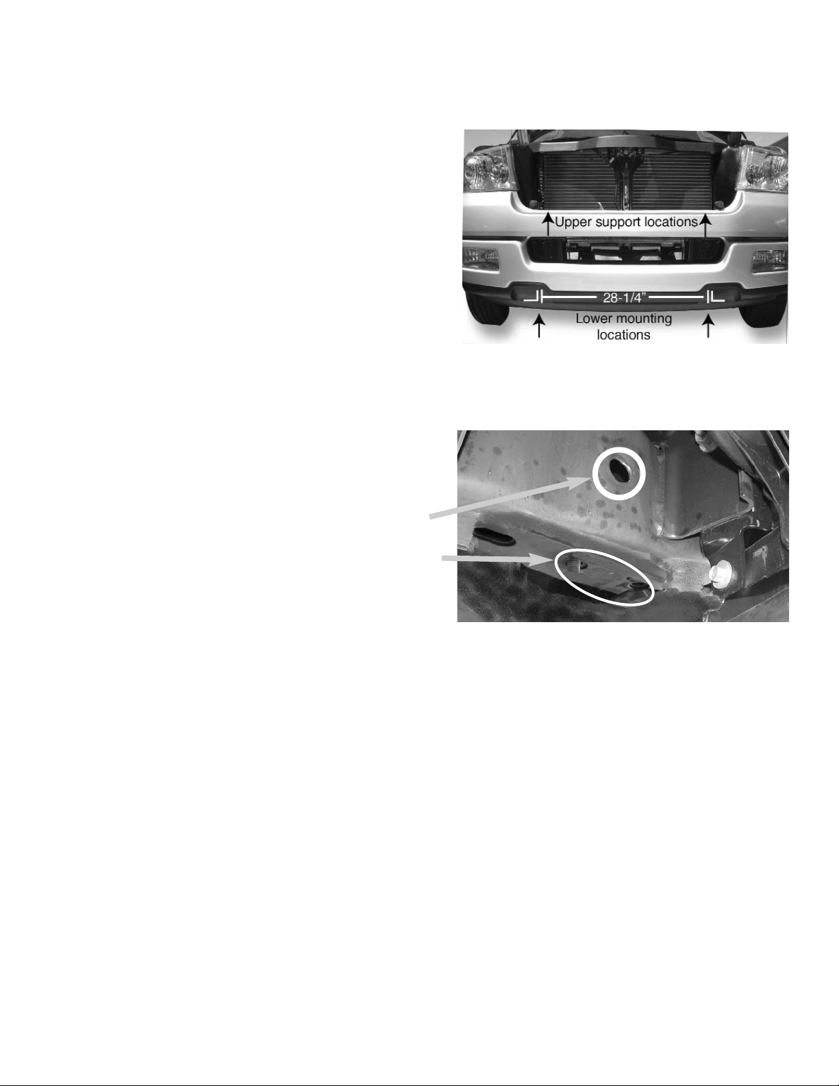
FOR ALL VEHICLES WITHOUT FRONT TOW HOOKS, START
ON THIS PAGE.
FOR ALL VEHICLES EQUIPPED WITH FRONT TOW HOOKS,
START ON FOLLOWING PAGE.
Cut 2 L-shaped slots 4” x 3” 28-1/4” apart, centered on the
vehicle (in the bumper cavities), as shown at right. The right
and left lower mounting brackets will need to be inserted
through these slots, so use the lower mounts as guides to cut
slots.
Insert (2) 7/16 bolts with extensions (item #10) into round
openings on each side of each frame rail (one bolt for front
hole and one bolt for back hole). Once bolts extend through
bottom of frame rail, fasten lower mounting bracket (item #2)
using (2) 7/16 flat washers (item #16), (2) 7/16” lockwashers (item #15), and (2) 7/16 hex nuts (item #17). Do not
tighten until later.
Do the same on the right side of vehicle.
Continue with installation on Page 4.
2
FRAME RAIL
Page 3
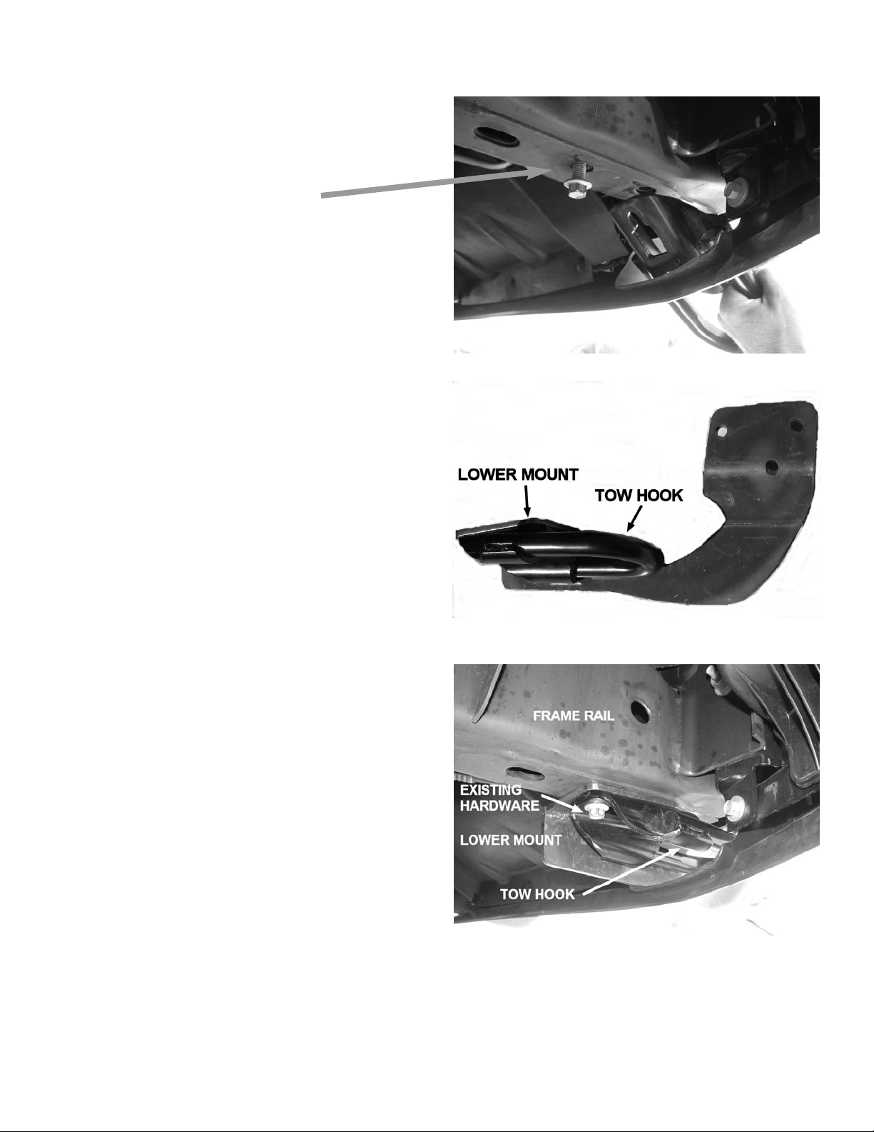
FOR ALL VEHICLES EQUIPPED WITH FRONT TOW
HOOKS, START ON THIS PAGE.
1. Remove tow hooks, but leave rear bolt threaded to nut
loose enough to slide tow hook off of frame.
2. Place lower mounting bracket (item #2) on top of tow
hook. The Lower mounting bracket will be mounted
between the tow hook and the frame.
3. Reinstall tow hook and lower mounting bracket using
existing hardware. Do not tighten until later.
3
Page 4

4
4. Lift center unit (item #1) into place between
lower mounts (with center unit outside brackets). Lift winch channel (item #22) between
lower mounts. Place channel and lower mount
gaskets (item #26) between center unit and
lower mounts, and between channel and lower
mounts. Secure using (2 per side) 3/8 x 1-1/4”
capscrews (item #11), (4 per side) 3/8 washers (item #18), and (2 per side) 3/8 locknuts
(item #19). Do not tighten until later.
For 2006-2007 Ford F-150, see additional instructions on the following page.
5. Remove the 10 mm bolt that is located on
either side of vehicle on the back side of
bumper as shown at right. The bolt will be
located approximately 2” inside of grille guard
plates. Hint: Lift upper support bracket into
place to help locate.
Passenger side shown.
6. Fasten upper support (item #4) using 10mm
x 40 mm capscrew (item #12) in place of
existing hardware. Upper support should rest
on top of bumper and align with hole in center
unit (item #1). Place upper support gasket
(item #27) between upper support and center
unit. Use (1) 3/8 x 1-1/4” capscrew (item
#11), (2) 3/8 washers (item #18) and (1)
3/8 locknut to secure upper support to center
unit. Do not tighten until later.
Repeat steps 5 and 6 for other side.
Page 5

IF NOT INSTALLING GRILLE GUARD KIT #295942,
SKIP STEPS 7-8
7. Place wrap shim (item #28) between Wraparound
units and side plates of center unit. Install right and
left Wraparound units (items #7 and #9) to side
plates of center unit using (3 per side) 1/4 x 1 capscrews (item #13), (6 per side) 1/4 flat washers, and
(3 per side) 1/4 locknuts. Do not tighten until later.
8. Install right and left Headlight Grilles (items #6 and
#8) to Wraparound units and side plates of center
unit using (2 per side) 1/4 x 1 capscrews (item #13),
(4 per side) 1/4 flat washers, and (2 per side) 1/4
locknuts. Far end of Headlight Grilles snap onto
Wraparound units. Do not tighten until later.
9. If needed, install the License Plate Assembly (item
#23) to the underside of the Channel (item #22)
using (2) 1/4 x 1 capscrews (item #13).
10. Align and tighten all bolts to proper torque (see
chart at right).
11. Install the fairlead using hardware furnished with the
winch. Refer to winch owner’s manual for complete
instructions. Tighten fairlead mounting bolts to proper
torque.
12. Install the winch in the Channel according to mounting
instructions in the winch owner’s manual, using hardware furnished with winch. Do not tighten mounting
bolts until electrical connections are complete.
13. Refer to winch owner’s manual for electrical connections. Push battery cables into loom (item #25) and
secure using cable ties (item #24) at each end of
loom. To improve appearance, wrap end of loom with
electrical tape.
Torque Value Chart
Bolt Torque, Torque,
Size ft-lbs. Nm
1/4-20 9.7 13
3/8-16 39 53
7/16 58 78
10 mm 45 61
6
Page 6

7
Page 7
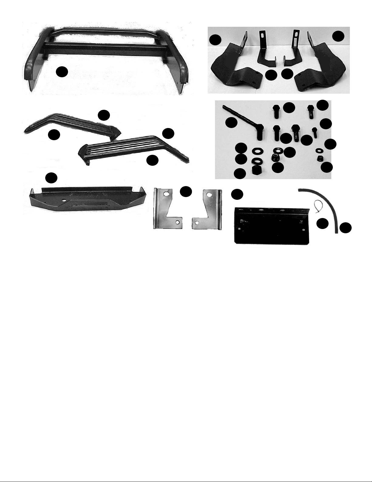
FORD F-150 SIERRA GRILLE GUARD KIT #295942
PARTS LIST
Item
No. Qty Part No. Description
1 1 R-P295942 Center Unit
2 1 R-LM943L Lower Mount Left
3 1 R-US943L Upper Support Left
4 1 R-LM943R Upper Support Right
5 1 R-US943R Lower Mount Right
10 4 TBOLT7/16X1.5- 7/16 x 1.5” bolt w/exten-
extension sion rod (used on 2WD
model only)
11 2 HCS3/8x1-1/4 Hex Capscrew 3/8x1-1/4”
12 2 HCS10mmx40mm Hex Capscrew 10 x 40 mm
13 2 HCS1/4-20x1 Hex Capscrew 1/4 x 1”
14 4 HCS3/8x1-1/2 Hex Capscrew 3/8 x 1-1/2
15 4 LOCKWASHER7/16 7/16 Lockwashers (used on
2 WD model only)
16 6 WASHERFLAT7/16 7/16 Flat Washers SAE
(used on 2 WD model only)
17 4 LNUT7/16 7/16 Nut (used on 2 WD
model only)
18 12 WASHERFLAT3/8 3/8 Flat Washer
19 6 LNUT3/8-16 3/8 Locknut
22 1 R-CHANNEL321 Winch Channel
Item
No. Qty Part No. Description
23 1 R-408127 License Plate Assembly
24 1 R-CABLETIE Package Cable Ties
25 1 R-LOOM Loom
26 4 R-GASKETCHAN Channel & Lower Mount
(not pictured) Gaskets (2 holes)
27 2 GASKETUS Upper Support Gasket (1 hole)
(not pictured
)
(Additional parts for 2006 F-150)
11 2 HCS3/8X1-1/4 3/8 x 1 1/4” Capscrew
18 4 WASHERFLAT3/8 3/8” Flat Washers
19 2 LNUT3/8-16 3/8” Nuts
29 2 Upper Support Ext. Brackets
30 2 8 mm x 35 mm Capscrews
WRAPAROUND KIT #295943 ADDITIONAL PARTS
6 1 R-G943R Headlight Grille Right
7 1 R-W943R Wraparound Right
8 1 R-G943L Headlight Grille Left
9 1 R-W943L Wraparound Left
13 10 HCS1/4x1 Hex Capscrew 1/4 x 1”
20 20 WASHFLAT1/4 1/4 Flat Washer
21 10 LNUT1/4 1/4 Locknut
28 2 R-GASKET943W Wrap Shim (not pictured)
1
2
3
4
5
7
9
10
15
16
17
11
14
18
19
12
13
20
21
22
23
25
24
6
8
8
30
29
 Loading...