

RAM Commercial PROMASTER Cargo Van 2019, PROMASTER Chassis Cab 2019, PROMASTER Window Van 2019, PROMASTER Cutaway Van 2019 User Manual
Page 1
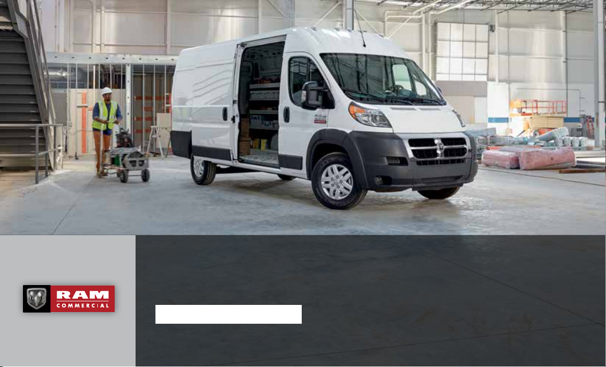
Properly secure all cargo.
RAM PROMASTER
2019 USER GUIDE
Page 2
IMPORTANT
Get warranty and other information online – you can review and print or download a copy of the Owner’s Manual, Navigation/
Uconnect manuals and the limited warranties provided by FCA US LLC for your vehicle by visiting www.mopar.com (U.S.) or
www.owners.mopar.ca (Canada). Click on the applicable link in the “Popular Topics” area of the www.mopar.com (U.S.) or
www.owners.mopar.ca (Canada) homepage and follow the instructions to select the applicable year, make and model of your vehicle.
If you are the first registered retail owner of your vehicle, you may obtain a complimentary printed copy of the Warranty Booklet by calling
1 866 726-4636 (U.S.) or 1 800 387-1143 (Canada) or by contacting your dealer.
This User Guide is intended to familiarize you with the important features of your vehicle. Your Owner’s Manual, Navigation/Uconnect manuals and
Warranty Booklet can be found by visiting the website on the back cover of your User Guide. We hope you find these resources useful. U.S. residents
can purchase replacement kits by visiting www.techauthority.com and Canadian residents can purchase replacement kits by calling 1 800 387-1143.
WARNING: Operating, servicing and maintaining a passenger vehicle or off-road highway
motor can expose you to chemicals including engine exhaust, carbon monoxide, phthalates,
and lead, which are known to the State of California to cause cancer and birth defects or
other reproductive harm. To minimize exposure, avoid breathing exhaust, do not idle the
engine except as necessary, service your vehicle in a well-ventilated area and wear gloves
or wash your hands frequently when servicing your vehicle. For more information go to:
www.p65Warnings.ca.gov/passenger-vehicle.
Page 3

Congratulations on selecting your new FCA
US LLC vehicle. Be assured that it represents
precision workmanship, distinctive styling,
and high quality.
ALWAYS drive safely and pay attention to the
road. ALWAYS drive safely with your hands on
the steering wheel. You have full responsibility and assume all risks related to the use of
the features and applications in this vehicle.
Only use the features and applications when
it is safe to do so. Failure to do so may result
in an accident involving serious injury or
death.
This guide illustrates and describes the operation of features and equipment that are
either standard or optional on this vehicle.
This guide may also include a description of
features and equipment that are no longer
available or were not ordered on this vehicle.
Please disregard any features and equipment
described in this guide that are not available
on this vehicle. FCA US LLC reserves the
right to make changes in design and specifications and/or make additions to or improve-
ments to its products without imposing any
obligation upon itself to install them on products previously manufactured.
This User Guide has been prepared to help
you quickly become acquainted with the important features of your vehicle. It contains
most things you will need to operate and
maintain the vehicle, including emergency
information.
When it comes to service, remember that your
authorized dealer knows your vehicle best,
has factory-trained technicians and genuine
®
MOPAR
faction.
parts, and cares about your satis-
HOW TO FIND YOUR OWNER’S MANUAL ONLINE
This publication has been prepared as a reference item to help you quickly become acquainted with the most important features
and processes of your vehicle. It contains
most things you will need to operate and
maintain the vehicle, including emergency
information and procedures.
This User Guide is not a replacement for the full
Owner’s Manual, and does not fully cover every
operation and procedure possible with your vehicle.
For more detailed descriptions of the topics
discussed in this User Guide, as well as
information covering features and processes
not covered in this User Guide, the full vehicle Owner’s Manual can be accessed for
free online in a printer-friendly PDF format.
To get the full Owner’s Manual or applicable
supplement for your vehicle, follow the appropriate web address below:
www.mopar.com/en-us/care/owners-manual.html
(U.S. Residents)
www.owners.mopar.ca (Canadian Residents)
FCA US LLC is committed to protecting our
environment and natural resources. By converting from paper to electronic delivery for
the majority of the user information for your
vehicle, together we greatly reduce the demand for tree-based products and lessen the
stress on our environment.
WELCOME FROM FCA US LLC
1
Page 4
HOW TO USE THIS MANUAL
Essential Information
Each time direction instructions (left/right or
forwards/backwards) about the vehicle are
given, these must be intended as regarding
an occupant in the driver's seat. Special
cases not complying with this rule will be
properly specified in the text.
The figures in this User Guide are provided by
way of example only: this might imply that
some details of the image do not correspond
to the actual arrangement of your vehicle.
HOW TO USE THIS MANUAL
In addition, the User Guide has been conceived considering vehicles with the steering
wheel on the left side; it is therefore possible
that in vehicles with the steering wheel on the
right side, the position or construction of
some controls is not exactly mirror-like with
respect to the figure.
To identify the chapter with the information
needed you can consult the index at the end
of this User Guide.
Chapters can be rapidly identified with dedicated graphic tabs, at the side of each odd
page. A few pages further there is a key for
getting to know the chapter order and the
relevant symbols in the tabs. There is always
a textual indication of the current chapter at
the side of each even page.
Symbols
Some vehicle components have colored labels whose symbols indicate precautions to
be observed when using this component.
Refer to “Warning Lights and Messages” in
“Getting To Know Your Instrument Panel” for
further information on the symbols used in
your vehicle.
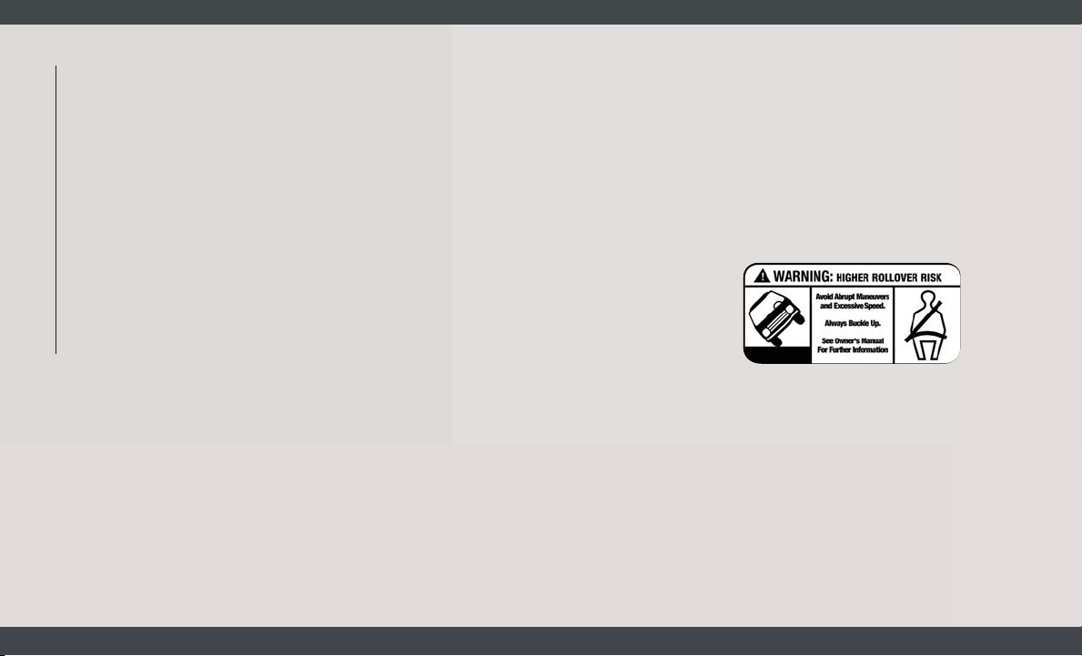
ROLLOVER WARNING
Utility vehicles have a significantly higher
rollover rate than other types of vehicles. This
vehicle has a higher ground clearance and a
higher center of gravity than many passenger
vehicles. It is capable of performing better in
a wide variety of off-road applications. Driven
in an unsafe manner, all vehicles can go out
of control. Because of the higher center of
gravity, if this vehicle is out of control it may
roll over while some other vehicles may not.
Do not attempt sharp turns, abrupt maneuvers, or other unsafe driving actions that can
cause loss of vehicle control. Failure to operate this vehicle safely may result in a collision, rollover of the vehicle, and severe or
fatal injury. Drive carefully.
Rollover Warning Label
Failure to use the driver and passenger seat
belts provided is a major cause of severe or
fatal injury. In fact, the U.S. government
notes that the universal use of existing seat
belts could cut the highway death toll by
10,000 or more each year and could reduce
disabling injuries by two million annually. In
2
Page 5

a rollover crash, an unbelted person is significantly more likely to die than a person wearing a seat belt. Always buckle up.
WARNINGS AND CAUTIONS
While reading this User Guide you will find a
series of WARNINGS to be followed to prevent incorrect use of components which
could cause accidents or injuries.
There are also CAUTIONS that must be followed to prevent against procedures that
could result in damage to your vehicle.
HOW TO USE THIS MANUAL
3
Page 6

4
Page 7
GRAPHICAL TABLE OF CONTENTS
GETTING TO KNOW YOUR VEHICLE
GETTING TO KNOW YOUR INSTRUMENT PANEL
SAFETY
STARTING AND OPERATING
IN CASE OF EMERGENCY
SERVICING AND MAINTENANCE
TECHNICAL SPECIFICATIONS
MULTIMEDIA
CUSTOMER ASSISTANCE
INDEX
Page 8

WELCOME FROM FCA US LLC
HOW TO FIND YOUR OWNER’S MANUAL ONLINE .... 1
HOW TO USE THIS MANUAL
HOW TO USE THIS MANUAL ...............2
Essential Information ................2
Symbols ........................2
ROLLOVER WARNING ...................2
WARNINGS AND CAUTIONS ...............3
GRAPHICAL TABLE OF CONTENTS
INSTRUMENT PANEL ...................9
INTERIOR .........................10
TABLE OF CONTENTS
GETTING TO KNOW YOUR VEHICLE
KEYS ...........................12
KeyFob ....................... 12
IGNITIONSWITCH ....................13
Mechanical Ignition Switch ...........13
Key-In-Ignition Reminder ............ 14
VEHICLE SECURITY ALARM — IF EQUIPPED .....14
To Arm The System ................14
To Disarm The System ..............14
Security System Manual Override ........ 14
SEATS .......................... 14
Heated Seats — If Equipped .......... 15
Adjustable Armrests — If Equipped ......16
HEAD RESTRAINTS ...................16
Front Head Restraint Adjustment ........16
Front Head Restraint Removal ..........17
STEERING WHEEL ....................17
Telescoping Steering Column ..........17
EXTERIOR LIGHTS ....................18
Multifunction Lever ................ 18
Headlights ..................... 18
ParkingLights ...................18
Turn Signals .....................18
Lane Change Assist ................ 19
WIPERS AND WASHERS ................ 19
Front Wiper Operation ...............19
CLIMATE CONTROLS ...................20
Manual Climate Control Overview ........20
Climate Control Functions ............ 25
Operating Tips ................... 25
HOOD ..........................27
Opening ....................... 27
Closing ........................27
INTERNAL EQUIPMENT .................28
Power Outlets .................... 28
Auxiliary Switches — If Equipped ........30
GETTING TO KNOW YOUR INSTRUMENT
PANEL
INSTRUMENT CLUSTER DISPLAY ............31
Location And Controls ...............31
Change Engine Oil .................32
WARNING LIGHTS AND MESSAGES .......... 32
RedWarningLights ................33
YellowWarningLights ............... 35
YellowIndicatorLights .............. 38
GreenIndicatorLights .............. 38
BlueIndicatorLights ............... 39
ONBOARD DIAGNOSTIC SYSTEM — OBD II ......39
Onboard Diagnostic System (OBD II)
Cybersecurity .................... 40
SAFETY
AUXILIARY DRIVING SYSTEMS .............41
Tire Pressure Monitoring System (TPMS) . . . 41
OCCUPANT RESTRAINT SYSTEMS ...........44
Occupant Restraint Systems Features ..... 44
Important Safety Precautions ..........44
Seat Belt Systems .................45
Supplemental Restraint Systems (SRS) .... 52
ChildRestraints ..................61
Transporting Pets .................66
SAFETY TIPS ......................66
Transporting Passengers ............. 66
Exhaust Gas ....................66
Safety Checks You Should Make Inside The
Vehicle .......................67
Periodic Safety Checks You Should Make
OutsideTheVehicle ................69
STARTING AND OPERATING
STARTING THE ENGINE ................. 70
Normal Starting .................. 70
ENGINE BREAK-IN RECOMMENDATIONS .......70
SPEED CONTROL — IF EQUIPPED ........... 71
ToActivate .....................71
To Set A Desired Speed ..............71
To Vary The Speed Setting ............ 71
To Accelerate For Passing ............72
To Resume Speed ................. 73
To Deactivate .................... 73
PARKSENSE REAR PARK ASSIST — IF EQUIPPED . . 73
PARKVIEW REAR BACK-UP CAMERA .......... 73
REFUELING THE VEHICLE ...............74
Materials Added To Fuel ............. 74
6
Page 9

TRAILER TOWING ....................75
Trailer Towing Weights (Maximum Trailer Weight
Ratings) ....................... 75
RECREATIONAL TOWING (BEHIND MOTORHOME,
ETC.) ...........................75
Towing This Vehicle Behind Another Vehicle . 75
Recreational Towing ................ 76
IN CASE OF EMERGENCY
BULB REPLACEMENT .................. 77
Replacement Bulbs ................77
FUSES ..........................78
Underhood Fuses .................78
Interior Fuses .................... 81
Right Central Pillar Fuses .............82
JACKING AND TIRE CHANGING ............. 82
Jack Location .................... 82
Spare Tire Removal ................ 84
Preparations For Jacking .............86
Jacking Instructions ................86
Wheel Covers ....................90
TIRE SERVICE KIT — IF EQUIPPED ...........90
TireServiceKitStorage .............. 90
Tire Service Kit Components And Operation . . 90
Tire Service Kit Usage Precautions .......91
SealingATireWithTireServiceKit .......92
JUMP STARTING .....................95
Preparations For Jump Start ........... 96
Jump Starting Procedure .............97
Battery Location .................. 98
IF YOUR ENGINE OVERHEATS .............98
GEAR SELECTOR OVERRIDE ...............99
FREEING A STUCK VEHICLE ..............99
TOWING A DISABLED VEHICLE ............100
Automatic Transmission ............ 101
ENHANCED ACCIDENT RESPONSE SYSTEM (EARS) . 101
EVENT DATA RECORDER (EDR) ............101
SERVICING AND MAINTENANCE
SCHEDULED SERVICING ................ 102
Maintenance Plan ................ 103
Heavy Duty Use Of The Vehicle ........ 105
ENGINE COMPARTMENT ...............106
3.6L Engine ....................106
RAISING THE VEHICLE .................107
TIRES ..........................107
TireSafetyInformation ............. 107
Tires — General Information ..........115
Tire Types ..................... 119
Spare Tires — If Equipped ...........120
Wheel And Wheel Trim Care .......... 122
DEPARTMENT OF TRANSPORTATION UNIFORM TIRE
QUALITY GRADES ...................124
Treadwear ..................... 124
Traction Grades ..................124
Temperature Grades ............... 125
TECHNICAL SPECIFICATIONS
WHEEL AND TIRE TORQUE SPECIFICATIONS ....126
Torque Specifications ..............126
FLUID CAPACITIES — GASOLINE ENGINE ...... 127
FLUIDS AND LUBRICANTS — GAS ENGINE ...... 127
Engine ....................... 127
Chassis ...................... 128
MOPAR ACCESSORIES ................. 129
Authentic Accessories By Mopar ....... 129
MULTIMEDIA
CYBERSECURITY ...................130
UCONNECT 3/3 NAV WITH 5-INCH DISPLAY ..... 131
Clock Setting ................... 132
Equalizer, Balance And Fade .......... 132
Radio Operation ................. 134
USB/Audio Jack (AUX)/Bluetooth Operation . 135
Navigation .....................136
UCONNECT SETTINGS .................136
STEERING WHEEL AUDIO CONTROLS .........137
LeftSwitch ....................137
RightSwitch ...................137
UCONNECT PHONE ...................138
Uconnect Phone (Bluetooth Hands Free
Calling) ....................... 138
Pairing (Wirelessly Connecting) Your Mobile
Phone To The Uconnect System ........ 139
Common Phone Commands (Examples) . . . 142
Mute (Or Unmute) Microphone During Call . 142
Transfer Ongoing Call Between Handset And
Vehicle ...................... 142
Phonebook ....................142
Voice Command Tips ..............143
Changing The Volume ..............143
UsingDoNotDisturb ..............143
Incoming Text Messages ............ 144
Helpful Tips And Common Questions To Improve
Bluetooth Performance With Your Uconnect
System ......................145
Regulatory And Safety Information
USA/CANADA ...................145
UCONNECT VOICE RECOGNITION QUICK TIPS ....146
Introducing Uconnect ..............146
GetStarted ....................147
Basic Voice Commands ............. 147
7
Page 10

Radio ....................... 148
Media ....................... 148
Phone .......................148
Voice Text Reply .................149
General Information ...............150
Additional Information .............150
CUSTOMER ASSISTANCE
IF YOU NEED ASSISTANCE .............. 151
FCA US LLC Customer Center ......... 151
FCA Canada Inc. Customer Center ......151
In Mexico Contact ................ 151
Puerto Rico And U.S. Virgin Islands ..... 151
Customer Assistance For The Hearing Or
Speech Impaired (TDD/TTY) ..........152
TABLE OF CONTENTS
ServiceContract ................. 152
REPORTING SAFETY DEFECTS .............153
In The 50 United States And
Washington, D.C. ................. 153
In Canada .....................153
PUBLICATION ORDER FORMS .............154
INDEX
........................155
8
Page 11
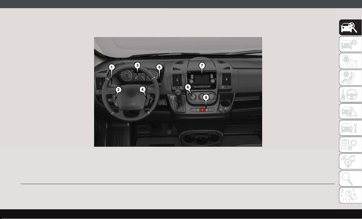
INSTRUMENT PANEL
Instrument Panel
1 — Multifunction Lever 5 — Windshield Wiper Lever
2 — Volume Control 6 — Climate Controls
3 — Instrument Cluster 7 — Uconnect System
4 — Scan Control 8 — Switch Panel
9
Page 12
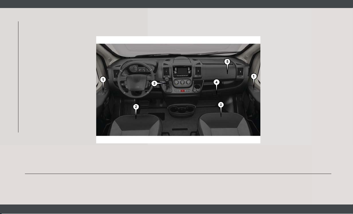
INTERIOR
GRAPHICAL TABLE OF CONTENTS
Interior
1 — Door Locks/Window Switches 4 — Glove Compartment
2 — Seats 5 — Passenger Airbag
3 — Gear Selector
10
Page 13

11
Page 14
KEYS
Key Fob
Your vehicle uses a key start ignition system.
The ignition system consists of a key fob with
a Remote Keyless Entry (RKE) and an ignition switch.
The key fob contains an integrated mechanical key. To use the mechanical key, simply
push the mechanical key release button.
The vehicle is supplied with a code card
containing key code numbers to order duplicate keys, and the authorized dealer that sold
you your new vehicle has the key code numbers for your vehicle locks. These numbers
can be used to order duplicate keys.
GETTING TO KNOW YOUR VEHICLE
12
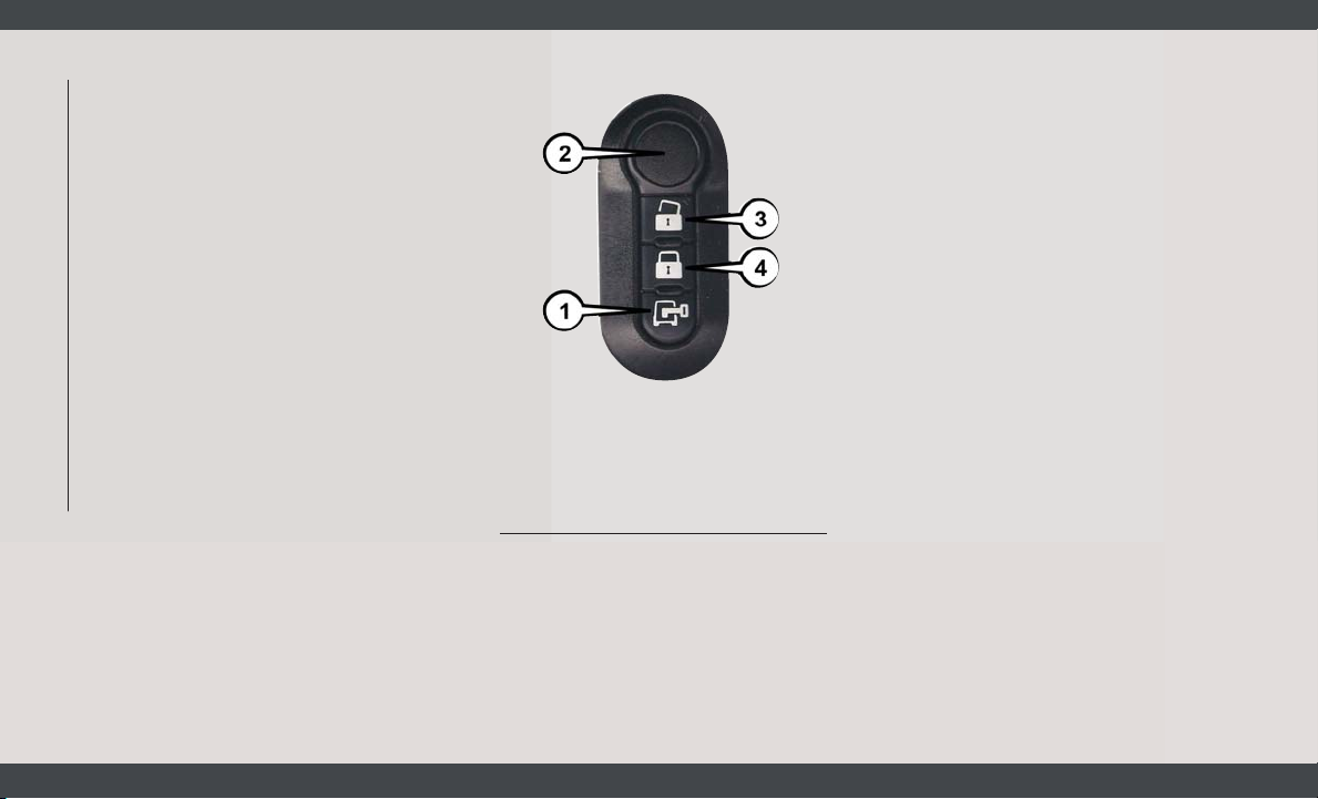
Key Fob
1 — Cargo Door Unlock Button
2 — Ignition Key Release
3 — Unlock
4 — Lock
Remote Keyless Entry (RKE)
This system allows you to lock or unlock the
doors from distances up to approximately
66 ft (20 m) using a hand-held key fob. The
key fob does not need to be pointed at the
vehicle to activate the system.
NOTE:
The key fob may not be able to be detected by
the vehicle if it is located next to a mobile
phone, laptop or other electronic device;
these devices may block the key fob’s wireless signal.
To Unlock The Doors
Push and release the unlock button on key
fob once to unlock only the front doors. Push
and release the cargo unlock button on key
fob once to unlock the cargo area (rear lateral
sliding doors and rear door). The turn signal
lights will flash twice to acknowledge the
unlock signal.
To Lock The Doors
Push and release the lock button on the key
fob to lock all doors. The turn signal lights
will flash once to acknowledge the signal. If a
door is open, the turn signal lights will flash
at an increased rate.
Locking Doors With A Key
1. Insert the key with either side up.
2. Turn the key to the right to lock the door.
3. Turn the key to the left to unlock the door.
Page 15
For maintenance procedures, refer to “Dealer
Service” in “Servicing And Maintenance” in
the Owner’s Manual for further information.
General Information
The following regulatory statement applies to
all radio frequency (RF) devices equipped in
this vehicle:
This device complies with Part 15 of the FCC
Rules and with Industry Canada licenseexempt RSS standard(s). Operation is subject to the following two conditions:
1. This device may not cause harmful interference, and
2. This device must accept any interference
received, including interference that may
cause undesired operation.
NOTE:
Changes or modifications not expressly approved by the party responsible for compliance could void the user’s authority to operate the equipment.
IGNITION SWITCH
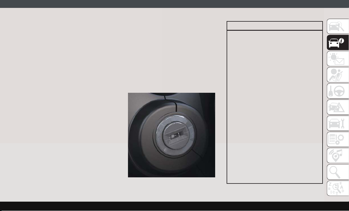
Mechanical Ignition Switch
1. Place the gear selector in PARK (if
equipped with an automatic
transmission).
2. Rotate the key to the STOP/OFF/LOCK
position.
3. Remove the key from the mechanical ignition switch.
Mechanical Ignition Switch
WARNING!
• Before exiting a vehicle, always shift the
automatic transmission into PARK, apply the parking brake, turn the vehicle
OFF, remove the key fobs from vehicle,
and lock all doors and lock your vehicle.
• Never leave children alone in a vehicle,
or with access to an unlocked vehicle.
Leaving children in a vehicle unattended
is dangerous for a number of reasons. A
child or others could be seriously or
fatally injured. Children should be
warned not to touch the parking brake,
brake pedal or the gear selector.
• Allowing children to be in a vehicle unattended is dangerous for a number of
reasons. A child or others could be seriously or fatally injured. Children should
be warned not to touch the parking
brake, brake pedal or the gear selector.
• Do not leave the key fob in or near the
vehicle, or in a location accessible to
children. A child could operate power
windows, other controls, or move the
vehicle.
13
Page 16
WARNING!
• Do not leave children or animals inside
parked vehicles in hot weather. Interior
heat build-up may cause serious injury
or death.
CAUTION!
An unlocked vehicle is an invitation. Always remove the key from the ignition and
lock all the doors when leaving the vehicle
unattended.
Key-In-Ignition Reminder
Opening the driver's door when the key is in
the ignition and the ignition switch position
is STOP/OFF/LOCK sounds a signal to remove
GETTING TO KNOW YOUR VEHICLE
the key.
VEHICLE SECURITY ALARM — IF EQUIPPED
The vehicle security alarm monitors the vehicle doors and ignition for unauthorized operation. When the vehicle security alarm is
activated, interior switches for door locks are
14
disabled. The system provides both audible
and visible signals. For the first three minutes, the horn will sound, and the turn signal
lights will flash. For an additional 15 minutes, only the turn signal lights will flash.
To Arm The System
To arm the system, the vehicle security alarm
will set when you use the key fob to lock the
doors. If a door or the hood is not properly
shut, the alarm system will not be armed.
To Disarm The System
Use the key fob to unlock the door and disarm
the system.
The vehicle security alarm will also disarm if
a programmed Sentry Key is inserted into the
ignition switch. To exit the alarming mode,
push the key fob unlock button, or insert a
programmed Sentry Key into the ignition
switch.
The vehicle security alarm is designed to
protect your vehicle. However, you can create
conditions where the system will give you a
false alarm. If one of the previously described
arming sequences has occurred, the vehicle
security alarm will arm regardless of whether
you are in the vehicle or not. If you remain in
the vehicle and open a door, the alarm will
sound. If this occurs, disarm the vehicle
security alarm.
Security System Manual Override
The vehicle security alarm will not arm/
disarm if you lock/unlock the doors using the
manual door lock plunger.
SEATS
Seats are a part of the Occupant Restraint
System of the vehicle.
WARNING!
• It is dangerous to ride in a cargo area,
inside or outside of a vehicle. In a collision, people riding in these areas are
more likely to be seriously injured or
killed.
• Do not allow people to ride in any area of
your vehicle that is not equipped with
seats and seat belts. In a collision,
Page 17
WARNING!
people riding in these areas are more
likely to be seriously injured or killed.
• Be sure everyone in your vehicle is in a
seat and using a seat belt properly.
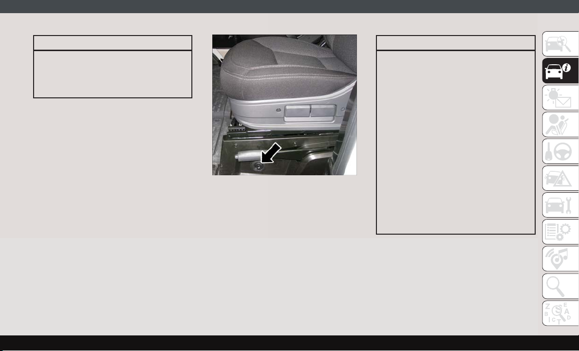
Heated Seats — If Equipped
On some models, the front driver and passenger seats may be equipped with heaters in
both the seat cushions and seatbacks. The
controls for the front heated seats are located
on the lower outboard side of the seat.
Heated Seat Switch
Push the switch once to turn on the heated
seats. Push the switch a second time to shut
the heating elements off.
NOTE:
Once a heat setting is selected, heat will be
felt within two to five minutes.
WARNING!
• Persons who are unable to feel pain to
the skin because of advanced age,
chronic illness, diabetes, spinal cord injury, medication, alcohol use, exhaustion or other physical condition must
exercise care when using the seat
heater. It may cause burns even at low
temperatures, especially if used for long
periods of time.
• Do not place anything on the seat or
seatback that insulates against heat,
such as a blanket or cushion. This may
cause the seat heater to overheat. Sitting in a seat that has been overheated
could cause serious burns due to the
increased surface temperature of the
seat.
15
Page 18
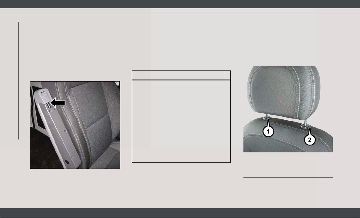
Adjustable Armrests — If
Equipped
The seat adjustable armrest can be raised
and adjusted for height. Underneath the front
of the armrest is the adjuster wheel which will
adjust the height of the armrest up or down.
Turn the adjuster wheel to the right or left to
adjust the height of the armrest up or down.
GETTING TO KNOW YOUR VEHICLE
Adjuster Wheel
HEAD RESTRAINTS
Head restraints are designed to reduce the
risk of injury by restricting head movement in
the event of a rear impact. Head restraints
should be adjusted so that the top of the head
restraint is located above the top of your ear.
WARNING!
• All occupants, including the driver,
should not operate a vehicle or sit in a
vehicle’s seat until the head restraints
are placed in their proper positions in
order to minimize the risk of neck injury
in the event of a crash.
• Head restraints should never be adjusted while the vehicle is in motion.
Driving a vehicle with the head restraints
improperly adjusted or removed could
cause serious injury or death in the
event of a collision.
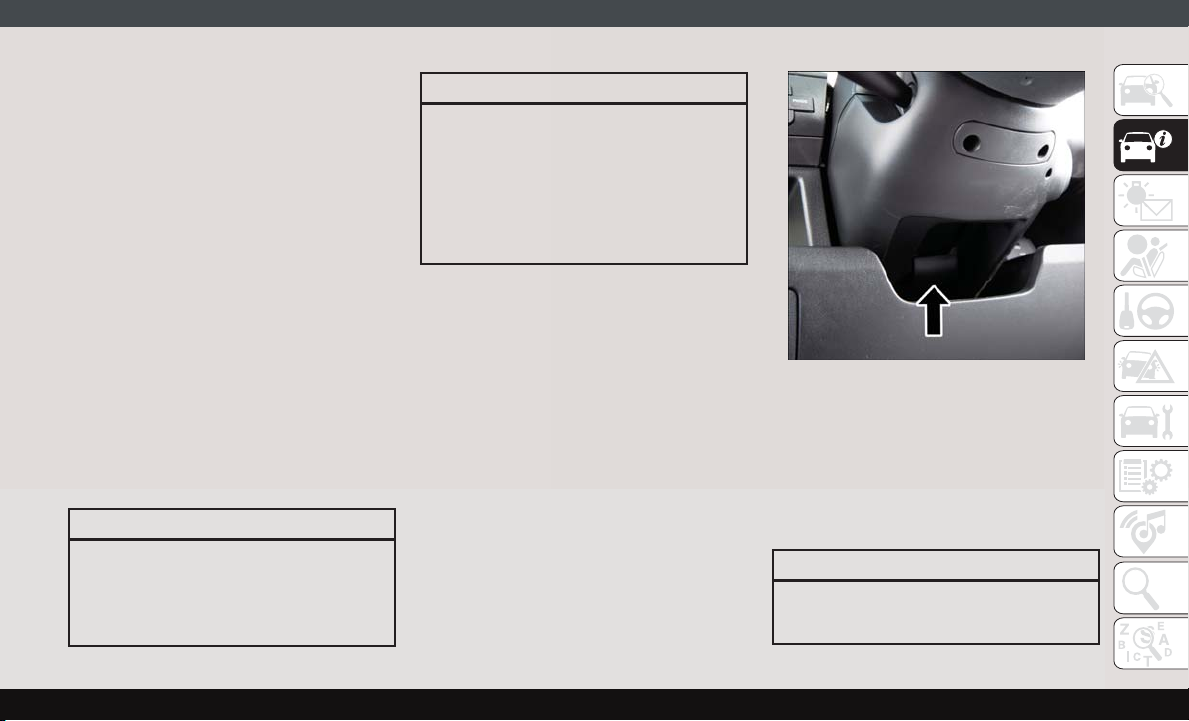
Front Head Restraint Adjustment
To raise the head restraint, pull upward on
the head restraint. To lower the head restraint, push the adjustment button located
on the base of the head restraint and push
downward on the head restraint.
Head Restraint
1 — Release Button
2 — Adjustment Button
16
Page 19
NOTE:
Do not reposition the head restraint 180 degrees to the incorrect position in an attempt
to gain additional clearance to the back of the
head.
Front Head Restraint Removal
To remove the head restraint, raise it up as far
as it can go. Then, push the adjustment
button and the release button at the base of
each post while pulling the head restraint up.
To reinstall the head restraint, put the head
restraint posts into the holes. Then, adjust it
to the appropriate height.
NOTE:
Do not reposition the head restraint 180 degrees to the incorrect position in an attempt
to gain additional clearance to the back of the
head.
WARNING!
WARNING!
head restraints in a location outside the
occupant compartment.
• ALL the head restraints MUST be reinstalled in the vehicle to properly protect
the occupants. Follow the re-installation
instructions above prior to operating the
vehicle or occupying a seat.
STEERING WHEEL
Telescoping Steering Column
This feature allows you to lengthen or shorten
the steering column. The telescoping control
handle is located below the steering wheel at
the end of the steering column.
Telescoping Control Handle
To unlock the steering column, pull the control handle up. To lengthen or shorten the
steering column, pull the steering wheel outward or push it inward as desired. To lock the
steering column in position, push the control
handle down until fully engaged.
• A loose head restraint thrown forward in
a collision or hard stop could cause serious injury or death to occupants of the
vehicle. Always securely stow removed
WARNING!
Do not adjust the steering column while
driving. Adjusting the steering column
17
Page 20
WARNING!
while driving or driving with the steering
column unlocked, could cause the driver
to lose control of the vehicle. Failure to
follow this warning may result in serious
injury or death.
EXTERIOR LIGHTS
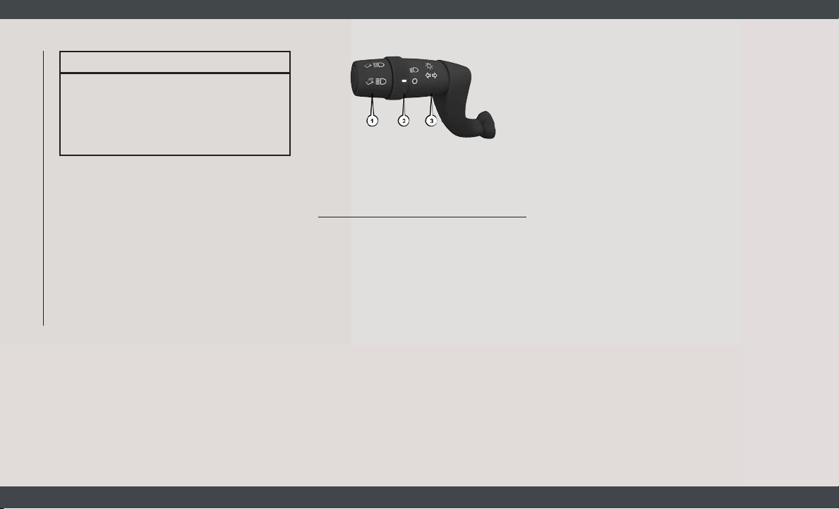
Multifunction Lever
The multifunction lever controls the operation of the headlights, parking lights, turn
signals, headlight beam selection and the
passing lights. The multifunction lever is
located on the left side of the steering column.
GETTING TO KNOW YOUR VEHICLE
Multifunction Lever
1 — Pull For High Beams
2 — Headlights
3 — Turn Signals
Headlights
To turn on the headlights, turn the end of the
multifunction lever to the headlight position.
When the headlight switch is on, the parking
lights, taillights, license plate light, the clearance lights and instrument panel lights are
also turned on. To turn off the headlights,
turn the end of the multifunction lever back
to the O (Off) position.
Parking Lights
These lights can only be turned on with
ignition key in the STOP position or removed,
by moving the end of the multifunction lever
to O (off) position and then to the headlight
position.
The warning light telltale in the instrument
panel comes on. The lights stay on until the
next ignition cycle is performed.
Turn Signals
Move the multifunction lever up or down and
the arrows on each side of the instrument
cluster flash to show proper operation of the
front and rear turn signal lights.
NOTE:
If either light remains on and does not flash,
or there is a very fast flash rate, check for a
defective outside light bulb. If an indicator
fails to light when the lever is moved, it would
suggest that the indicator bulb is defective.
18
Page 21
Lane Change Assist
Tap the lever up or down once, without moving beyond the detent, and the turn signal
(right or left) will flash five times then automatically turn off.
WIPERS AND WASHERS
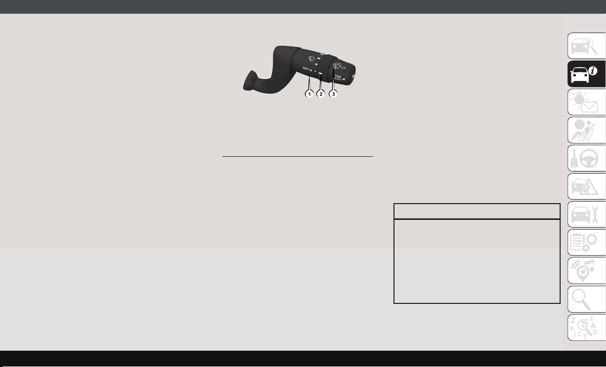
Front Wiper Operation
The windshield wiper/washer lever is located
on the right side of the steering column.
There are five different modes of operation
for the front windshield wipers. The windshield wiper lever can be raised or lowered to
access the modes.
NOTE:
The windshield wipers/washers will only operate with the ignition in the ON/RUN position.
Wiper Washer Lever
1 — Mist
2 — Intermittent, Low And High
3 — Washer
Intermittent Wiper System
Push the lever downward to the first detent
and rotate the center ring to use one of the
four intermittent wiper settings when weather
conditions make a single wiping cycle, with a
variable delay between cycles, desirable.
Low Speed
Push the lever downward to the second detent. The wipers will operate at low speed.
High Speed
Push the lever downward to the third detent.
The wipers will operate at high speed.
Windshield Washer Operation
To use the washer, pull the windshield wiper/
washer lever toward the steering wheel to
activate. The wipers will activate automatically for three cycles after the lever is released, and then resume the intermittent
interval previously selected.
If the lever is pulled while in the off position,
the wipers will operate for three cycles and
then turn off.
WARNING!
Sudden loss of visibility through the windshield could lead to a collision. You might
not see other vehicles or other obstacles.
To avoid sudden icing of the windshield
during freezing weather, warm the windshield with the defroster before and during
windshield washer use.
19
Page 22

Mist Feature
Use the Mist feature when weather conditions make occasional usage of the wipers
necessary. Push the lever upward to the MIST
position and release for a single wiping cycle.
NOTE:
The mist feature does not activate the washer
pump; therefore, no washer fluid will be
sprayed on the windshield. The wash function must be used in order to spray the
windshield with washer fluid.
CLIMATE CONTROLS
The Climate Control System allows you to
regulate the temperature, air flow, and direction of air circulating throughout the ve-
GETTING TO KNOW YOUR VEHICLE
hicle. The controls are located on the touchscreen (if equipped) and on the instrument
panel below the radio.
Manual Climate Control Overview
The Manual Temperature Controls consist of
a series of three outer rotary dials (blower
speed, temperature and mode) and three
inner push buttons (Recirculation, A/C, Rear
Window Defroster).
20
Page 23
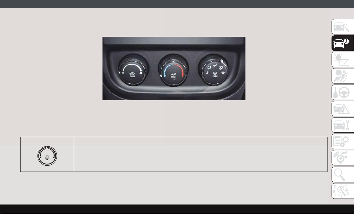
Manual Climate Control Descriptions
Icon Description
A/C Button
Push the A/C button to engage the Air Conditioning (A/C). A LED will illuminate when the A/C system is engaged.
Manual Climate Controls
21
Page 24
GETTING TO KNOW YOUR VEHICLE
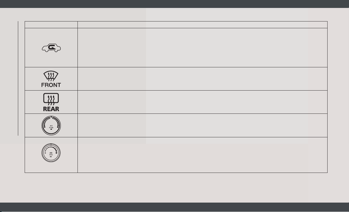
Icon Description
Recirculation Button
Press and release this button to change the system between recirculation mode and outside air mode. Recirculation can
be used when outside conditions such as smoke, odors, dust, or high humidity are present. Recirculation can be used in
all modes except for Defrost. Recirculation may be unavailable if conditions exist that could create fogging on the inside
of the windshield. The A/C can be deselected manually without disturbing the mode control selection. Continuous use
of the Recirculation mode may make the inside air stuffy and window fogging may occur. Extended use of this mode is
not recommended.
Front Defrost Mode
Turn the Knob to the Front Defrost position. Air comes from the windshield and side window demist outlets. When the
defrost button is selected, the blower level will increase. Use Defrost mode with maximum temperature settings for best
windshield and side window defrosting and defogging.
Rear Defrost Button
Push and release the Rear Defrost Control button to turn ON the rear window defroster and the heated outside mirrors
(if equipped). An indicator will illuminate when the rear window defroster is ON. The rear window defroster automatically turns OFF after ten minutes.
Temperature Control
Use this control to regulate the temperature of the air inside the passenger compartment. Rotating the knob counterclockwise, from top center into the blue area of the scale, indicates cooler temperatures. Rotating the knob clockwise,
into the red area, indicates warmer temperatures.
Blower Control
There are seven blower speeds. Use this control to regulate the amount of air forced through the system in any mode
you select. The blower speed increases as you move the control clockwise from the OFF position.
NOTE:
Depending on the configuration, your vehicle may be equipped with four blower speeds.
22
Page 25
Icon Description
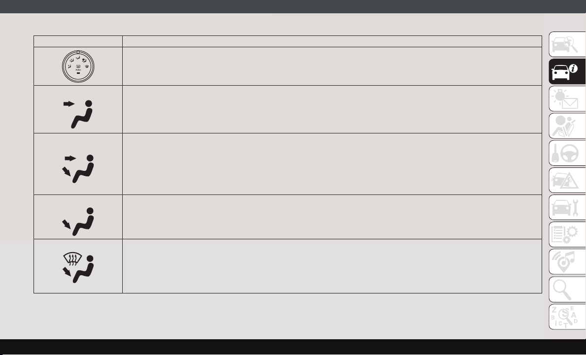
Modes Control
Turn the knob to change the airflow distribution mode. The airflow distribution mode can be adjusted so air comes from
the instrument panel outlets, floor outlets, defrost outlets and demist outlets. The Mode settings are as follows:
Panel Mode
Panel Mode
Air comes from the outlets in the instrument panel. Each of these outlets can be individually adjusted to direct the flow
of air. The air vanes of the center outlets and outboard outlets can be moved up and down or side to side to regulate
airflow direction. There is a shut off wheel located below the air vents to shut off or adjust the amount of airflow from
these outlets.
Bi-Level Mode
Bi-Level Mode
Air comes from the instrument panel outlets and floor outlets. A slight amount of air is directed through the defrost and
side window demister outlets.
NOTE:
Bi-Level mode is designed under comfort conditions to provide cooler air out of the panel outlets and warmer air from
the floor outlets.
Floor Mode
Floor Mode
Air comes from the floor outlets. A slight amount of air is directed through the defrost and side window demister outlets.
Mix Mode
Mix Mode
Air is directed through the floor, defrost, and side window demister outlets. This setting works best in cold or snowy conditions that require extra heat to the windshield. This setting is good for maintaining comfort while reducing moisture
on the windshield.
23
Page 26
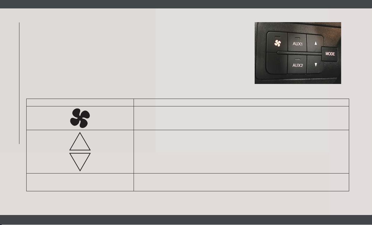
Additional Rear Climate Control — If
Equipped
These switches, mounted on the instrument
panel to the left of the steering column,
activate the additional rear heating/air conditioning system.
Icon Description
GETTING TO KNOW YOUR VEHICLE
NOTE:
These switches must be enabled for operation by the Upfitter.
Additional Rear Climate Controls Switches
Rear Blower Control
Push this button to turn on the rear climate controls. An indicator light will turn on when the
rear climate control is on.
Rear Temperature Control
• Rear Passenger Temperature Up Button To change the temperature in the rear of the vehicle, push
temperature control up button to raise the temperature.
Rear Passenger Temperature Down Button To change the temperature in the rear of the vehicle,
•
push temperature control down button to lower the temperature.
24
MODE
Rear MODE Button
Push this button to change the air distribution mode for the rear passengers.
Page 27
Climate Control Functions
A/C (Air Conditioning)
The Air Conditioning (A/C) button allows the
operator to manually activate or deactivate
the air conditioning system. When the air
conditioning system is turned on, cool dehumidified air will flow through the outlets into
the cabin. For improved fuel economy, press
the A/C button to turn off the air conditioning
and manually adjust the blower and airflow
mode settings. Also, make sure to select only
Panel, Bi-Level or Floor modes.
NOTE:
• For Manual Climate Controls, if the system
is in Mix, Floor or Defrost Mode, the A/C can
be turned off, but the A/C system shall
remain active to prevent fogging of the
windows.
• If fog or mist appears on the windshield or
side glass, select Defrost mode, and increase blower speed if needed.
• If your air conditioning performance seems
lower than expected, check the front of the
A/C condenser (located in front of the radiator), for an accumulation of dirt or insects. Clean with a gentle water spray from
the front of the radiator and through the
condenser.
Recirculation
In cold weather, use of Recirculation mode
may lead to excessive window fogging. The
Recirculation feature may be unavailable if
conditions exist that could create fogging on
the inside of the windshield. On systems with
Manual Climate Controls, the Recirculation
mode is not allowed in Defrost mode to improve window clearing operation. Recirculation is disabled automatically if this mode is
selected. Attempting to use Recirculation
while in this mode causes the LED in the
control button to blink and then turns off.
Operating Tips
Summer Operation
The engine cooling system must be protected
with a high-quality antifreeze coolant to provide proper corrosion protection and to protect against engine overheating. A solution of
50% OAT (Organic Additive Technology) coolant that meets the requirements of FCA Material Standard MS.90032 and 50% water is
recommended. Refer to “Fluids And Lubricants” in “Technical Specifications” in your
Owner’s Manual for proper coolant selection.
Winter Operation
Use of the air Recirculation mode during
winter months is not recommended because
it may cause window fogging.
25
Page 28
Vacation Storage
Any time you store your vehicle or keep it out
of service (i.e., vacation) for two weeks or
more, run the air conditioning system at idle
for about five minutes in the fresh air and
high blower setting. This will ensure adequate system lubrication to minimize the
possibility of compressor damage when the
system is started again.
Window Fogging
Interior fogging on the windshield can be
quickly removed by turning the mode selector
to Defrost. The Defrost/Floor mode can be
used to maintain a clear windshield and provide sufficient heating. If side window fogging becomes a problem increase blower
speed. Vehicle windows tend to fog on the
GETTING TO KNOW YOUR VEHICLE
inside in mild but rainy or humid weather.
NOTE:
Recirculate without A/C should not be used
for long periods, as fogging may occur.
CAUTION!
Failure to follow these cautions can cause
damage to the heating elements:
• Use care when washing the inside of
the rear window. Do not use abrasive
window cleaners on the interior surface
of the window. Use a soft cloth and a
mild washing solution, wiping parallel
to the heating elements. Labels can be
peeled off after soaking with warm
water.
• Do not use scrapers, sharp instruments, or abrasive window cleaners on
the interior surface of the window.
• Keep all objects a safe distance from
the window.
Outside Air Intake
Make sure the air intake, located directly in
front of the windshield, is free of obstructions
such as leaves. Leaves collected in the air
intake may reduce airflow, and if they enter
the plenum, they could plug the water drains.
In winter months, make sure the air intake is
clear of ice, slush, and snow.
A/C Air Filter
The climate control system filters outside air
containing dust, pollen and some odors.
Strong odors cannot be totally filtered out.
Refer to “Dealer Service” in “Servicing and
Maintenance” in your Owner’s Manual for
filter replacement instructions.
26
Page 29
HOOD
Opening
To open the hood, two latches must be released.
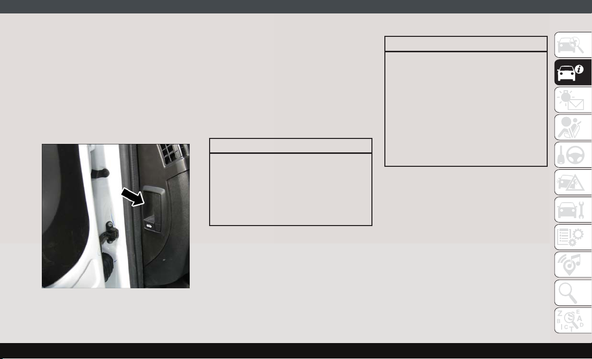
1. Open the driver’s door to gain access to
the hood release lever. Pull the hood release lever located on the side of the
instrument panel.
Hood Release
2. Move to the outside of the vehicle, reach
into the opening beneath the center of the
hood and push the safety latch lever to the
right to release it, before raising the hood.
3. Raise the hood and place the hood prop
rod in hood slot to secure the hood in the
open position.
Closing
WARNING!
Be sure the hood is fully latched before
driving your vehicle. If the hood is not fully
latched, it could open when the vehicle is
in motion and block your vision. Failure to
follow this warning could result in serious
injury or death.
CAUTION!
To prevent possible damage:
• Before closing hood, make sure the hood
prop rod is fully seated into its storage
retaining clips.
• Do not slam the hood to close it. Use a
firm downward push at the center front
edge of the hood to ensure that both
latches engage. Never drive your vehicle
unless the hood is fully closed, with both
latches engaged.
27
Page 30
INTERNAL EQUIPMENT
Power Outlets
Passenger Compartment Power Outlet
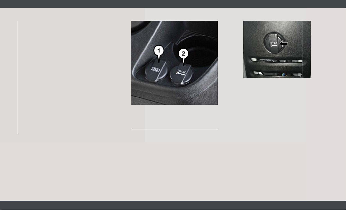
The power outlet is located on the Instrument
Panel Passenger Compartment near the cup
holder. It only operates with the ignition key
at MAR/ON.
GETTING TO KNOW YOUR VEHICLE
Front USB Port And Power Outlet
1 — USB Charge Only Port
2 — Front Power Outlet
Load Compartment Power Outlet — If Equipped
The Load Compartment Power Outlet is located in rear cargo compartment. The outlet
can be is used for powering 12 Volt adaptive
accessories and recharging communications
devices.
Load Compartment Power Outlet
NOTE:
Do not connect devices with power higher
than 180 W to the socket. Do not damage the
socket by using unsuitable adaptors.
28
Page 31
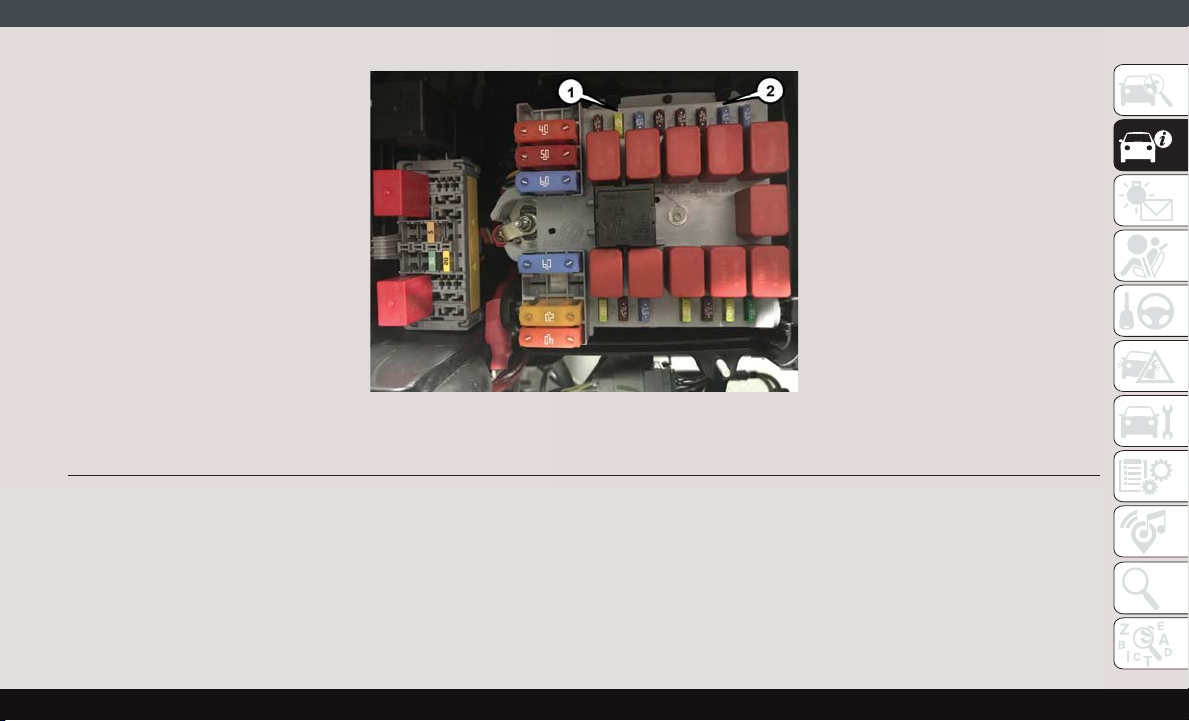
1 — F14 Fuse 20 Amp Yellow Front Power Outlet
2 — F09 Fuse 15 Amp Blue Rear Power Outlet
Power Outlet Fuses — Under Hood
29
Page 32
WARNING!
To avoid serious injury or death:
• Only devices designed for use in this
type of outlet should be inserted into any
12 Volt outlet.
• Do not touch with wet hands.
• Close the lid when not in use and while
driving the vehicle.
• If this outlet is mishandled, it may cause
an electric shock and failure.
CAUTION!
• Many accessories that can be plugged in
draw power from the vehicle's battery,
even when not in use (i.e., cellular
phones, etc.). Eventually, if plugged in
GETTING TO KNOW YOUR VEHICLE
long enough, the vehicle's battery will
discharge sufficiently to degrade battery
life and/or prevent the engine from starting.
30
CAUTION!
• Accessories that draw higher power (i.e.,
coolers, vacuum cleaners, lights, etc.)
will degrade the battery even more
quickly. Only use these intermittently
and with greater caution.
• After the use of high power draw accessories, or long periods of the vehicle not
being started (with accessories still
plugged in), the vehicle must be driven a
sufficient length of time to allow the
generator to recharge the vehicle's battery.
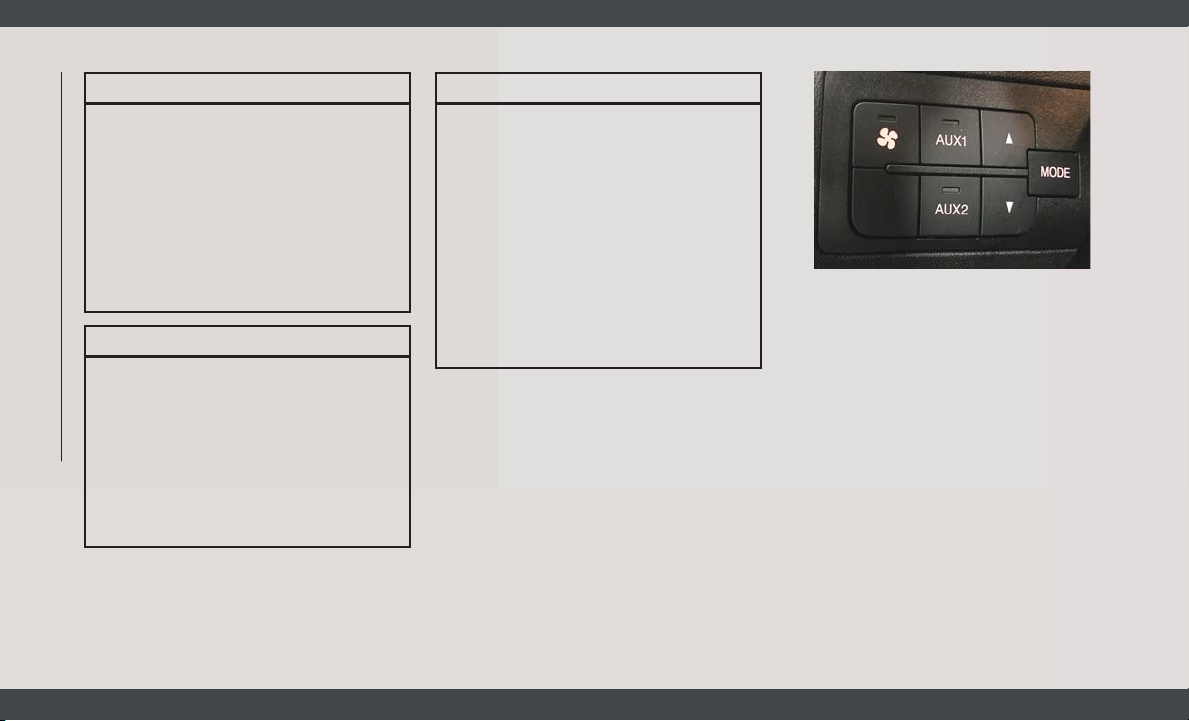
Auxiliary Switches — If Equipped
Your vehicle may be equipped with two auxiliary switches located on the instrument
panel to the left of the steering column which
can be used to power various electronic devices. Connections to the switches are found
in the right central pillar fuse panel at the
base of the passenger side B pillar.
Auxiliary Upfitter Switches
Auxiliary Switch 1 is configured to constant
battery feed, while Auxiliary Switch 2 is configured to ignition feed.
For further information on using the auxiliary
switches, please refer to the Ram Body Builders Guide by accessing
www.rambodybuilder.com and choosing the
appropriate links.
Page 33
INSTRUMENT CLUSTER DISPLAY
Your vehicle will be equipped with an instrument cluster display, which offers useful information to the driver. With the ignition in
the STOP/OFF mode, opening/closing of a
door will activate the display for viewing, and
display the total miles, or kilometers, in the
odometer. Your instrument cluster display is
designed to display important information
about your vehicle’s systems and features.
Using a driver interactive display located on
the instrument panel, your instrument cluster
display can show you how systems are working and give you warnings when they are not.
The steering wheel mounted controls allow
you to scroll through the main menus and
submenus. You can access the specific information you want and make selections and
adjustments.
Location And Controls
The instrument cluster display features a
driver-interactive display that is located in
the instrument cluster.
This system allows the driver to select a
variety of useful information by pushing the
switches mounted on the instrument panel.
Examples of menu items are:
• Speed Beep
• Buzzer Volume
• Seat Belt Buzzer (Just Available After SBR
Disable Made By CHR Service)
• Exit Menu
If equipped with a Uconnect system, some
customer programmable features will display
in the radio. Refer to the “Uconnect Settings” in “Multimedia” in the Owner’s
Manual for further information.
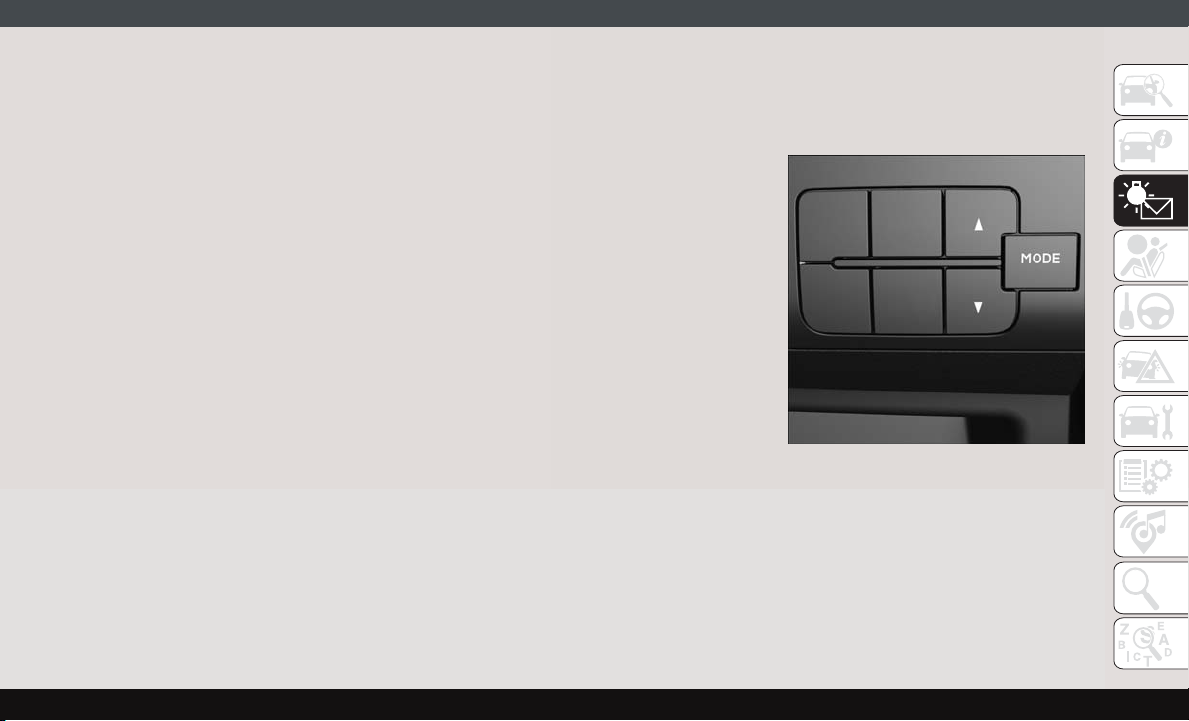
The system allows the driver to select information by pushing the following buttons
mounted on the instrument panel to the left
of the steering column:
Display Control Buttons
NOTE:
The MODE button must be pushed prior to
pressing the up arrow and down arrow buttons.
31
Page 34

• MODE Button
Push and hold the MODE button for a time
longer than one second to access/select the
information screens or submenu screens of
a main menu item. Push and hold the MODE
button for two seconds to reset displayed/
selected features that can be reset.
• Up Arrow Button
Push and release the up arrow button to
scroll upward through the main menu and
submenus or adjust the illumination on the
instrument panel when the headlights are
on.
• Down Arrow Button
Push and release the down arrow button to
scroll downward through the main menu
and submenus or adjust the illumination on
the instrument panel when the headlights
are on.
GETTING TO KNOW YOUR INSTRUMENT PANEL
Change Engine Oil
Your vehicle is equipped with an engine oil
change indicator system. The “Change Engine Oil” message will display in the instrument cluster display. The engine oil change
indicator system is duty cycle based, which
means the engine oil change interval may
fluctuate, dependent upon your personal
driving style.
Unless reset, this message will continue to
display each time you turn the ignition switch
to the ON/RUN position. To turn off the
message temporarily, push and release the
MODE button. To reset the oil change indicator system (after performing the scheduled
maintenance), refer to the following procedure.
1. Turn the ignition switch to the ON position
(do not start the engine).
2. Fully push the accelerator pedal slowly,
three times, within 10 seconds.
3. Turn the ignition switch to the OFF/LOCK
position.
NOTE:
If the indicator message illuminates when
you start the vehicle, the oil change indicator
system did not reset. If necessary, repeat this
procedure.
WARNING LIGHTS AND MESSAGES
The warning/indicator lights will illuminate in
the instrument panel together with a dedicated message and/or acoustic signal when
applicable. These indications are indicative
and precautionary and as such must not be
considered as exhaustive and/or alternative
to the information contained in the Owner’s
Manual, which you are advised to read carefully in all cases. Always refer to the information in this chapter in the event of a failure
indication. All active telltales will display first
if applicable. The system check menu may
appear different based upon equipment options and current vehicle status. Some telltales are optional and may not appear.
32
Page 35
Red Warning Lights
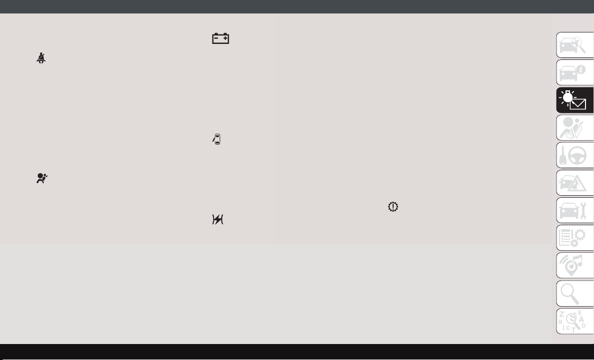
— Seat Belt Reminder Warning Light
When the ignition is first placed in the ON/
RUN or MAR/ON/RUN position, if the driver’s
seat belt is unbuckled, a chime will sound
and the light will turn on. When driving, if the
driver or front passenger seat belt remains
unbuckled, the Seat Belt Reminder Light will
flash or remain on continuously and a chime
will sound. Refer to “Occupant Restraints
Systems” in “Safety” for further information.
— Air Bag Warning Light
This light will turn on for four to eight seconds
as a bulb check when the ignition is placed in
the ON/RUN or MAR/ON/RUN position. If the
light is either not on during startup, stays on,
or turns on while driving, have the system
inspected at an authorized dealer as soon as
possible. This light will illuminate with a
single chime when a fault with the Air Bag
Warning Light has been detected, it will stay
on until the fault is cleared. If the light comes
on intermittently or remains on while driving,
have an authorized dealer service the vehicle
immediately.
— Battery Charge Warning Light
This warning light will illuminate when the
battery is not charging properly. If it stays on
while the engine is running, there may be a
malfunction with the charging system. Contact an authorized dealer as soon as possible.
This indicates a possible problem with the
electrical system or a related component.
— Door Open Warning Light
This indicator will illuminate when one or
more door(s) are not fully closed.
NOTE:
If the vehicle is moving and a door is opened,
there will also be a single chime.
— Electronic Throttle Control (ETC)
Warning Light
This warning light will illuminate to inform of
a problem with the Electronic Throttle Control (ETC) system. If a problem is detected
while the vehicle is running, the light will
either stay on or flash depending on the
nature of the problem. Cycle the ignition
when the vehicle is safely and completely
stopped and the transmission is placed in the
PARK position. The light should turn off. If
the light remains on with the vehicle running,
your vehicle will usually be drivable; however,
see an authorized dealer for service as soon
as possible.
If the light continues to flash when the vehicle is running, immediate service is required and you may experience reduced performance, an elevated/rough idle, or engine
stall and your vehicle may require towing. The
light will come on when the ignition is placed
in the ON/RUN or MAR/ON/RUN position and
remain on briefly as a bulb check. If the light
does not come on during starting, have the
system checked by an authorized dealer.
— Transmission Fault Warning Light
This light will illuminate (together with a
message in the instrument cluster display
and a buzzer) to indicate a transmission fault.
Contact an authorized dealer if the message
remains after restarting the engine.
33
Page 36
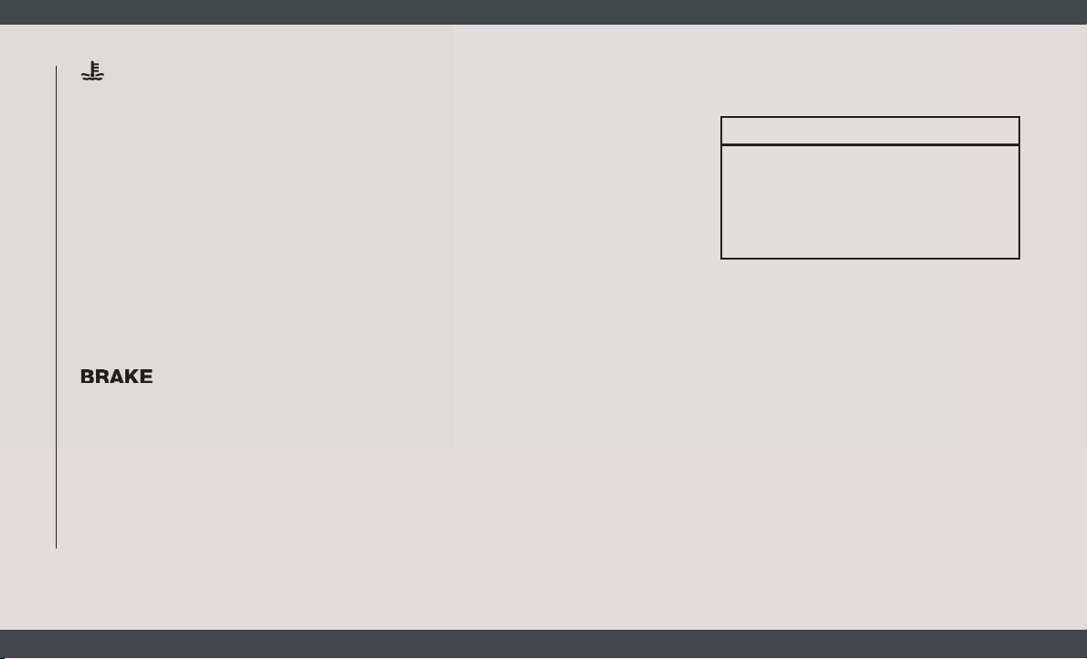
— Engine Temperature Warning Light
This light warns of an overheated engine
condition. If the engine coolant temperature
is too high, this indicator will illuminate and
a single chime will sound.
If the light turns on while driving, safely pull
over and stop the vehicle. If the A/C system is
on, turn it off. Also, shift the transmission
into NEUTRAL and idle the vehicle. If the
temperature reading does not return to normal, turn the engine off immediately and call
for service. Refer to “If Your Engine Overheats” in “In Case Of Emergency” for further
information.
— Brake Warning Light
This warning light monitors various brake
functions, including brake fluid level and
parking brake application. If the brake light
turns on it may indicate that the parking
brake is applied, that the brake fluid level is
low, or that there is a problem with the
anti-lock brake system reservoir.
GETTING TO KNOW YOUR INSTRUMENT PANEL
If the light remains on when the parking
brake has been disengaged, and the fluid
level is at the full mark on the master cylinder
34
reservoir, it indicates a possible brake hydraulic system malfunction or that a problem
with the Brake Booster has been detected by
the Anti-Lock Brake System (ABS) / Electronic Stability Control (ESC) system. In this
case, the light will remain on until the condition has been corrected. If the problem is
related to the brake booster, the ABS pump
will run when applying the brake, and a brake
pedal pulsation may be felt during each stop.
The dual brake system provides a reserve
braking capacity in the event of a failure to a
portion of the hydraulic system. A leak in
either half of the dual brake system is indicated by the Brake Warning Light, which will
turn on when the brake fluid level in the
master cylinder has dropped below a specified level.
The light will remain on until the cause is
corrected.
NOTE:
The light may flash momentarily during sharp
cornering maneuvers, which change fluid
level conditions. The vehicle should have
service performed, and the brake fluid level
checked.
If brake failure is indicated, immediate repair
is necessary.
WARNING!
Driving a vehicle with the red brake light
on is dangerous. Part of the brake system
may have failed. It will take longer to stop
the vehicle. You could have a collision.
Have the vehicle checked immediately.
Vehicles equipped with the Anti-Lock Brake
System (ABS) are also equipped with Electronic Brake Force Distribution (EBD). In the
event of an EBD failure, the Brake Warning
Light will turn on along with the ABS Light.
Immediate repair to the ABS system is required.
Operation of the Brake Warning Light can be
checked by turning the ignition switch from
the OFF position to the ON/RUN position.
The light should illuminate for approximately
two seconds. The light should then turn off
unless the parking brake is applied or a brake
fault is detected. If the light does not illuminate, have the light inspected by an authorized dealer.
Page 37
The light also will turn on when the parking
brake is applied with the ignition switch in
the ON/RUN position.
NOTE:
This light shows only that the parking brake is
applied. It does not show the degree of brake
application.
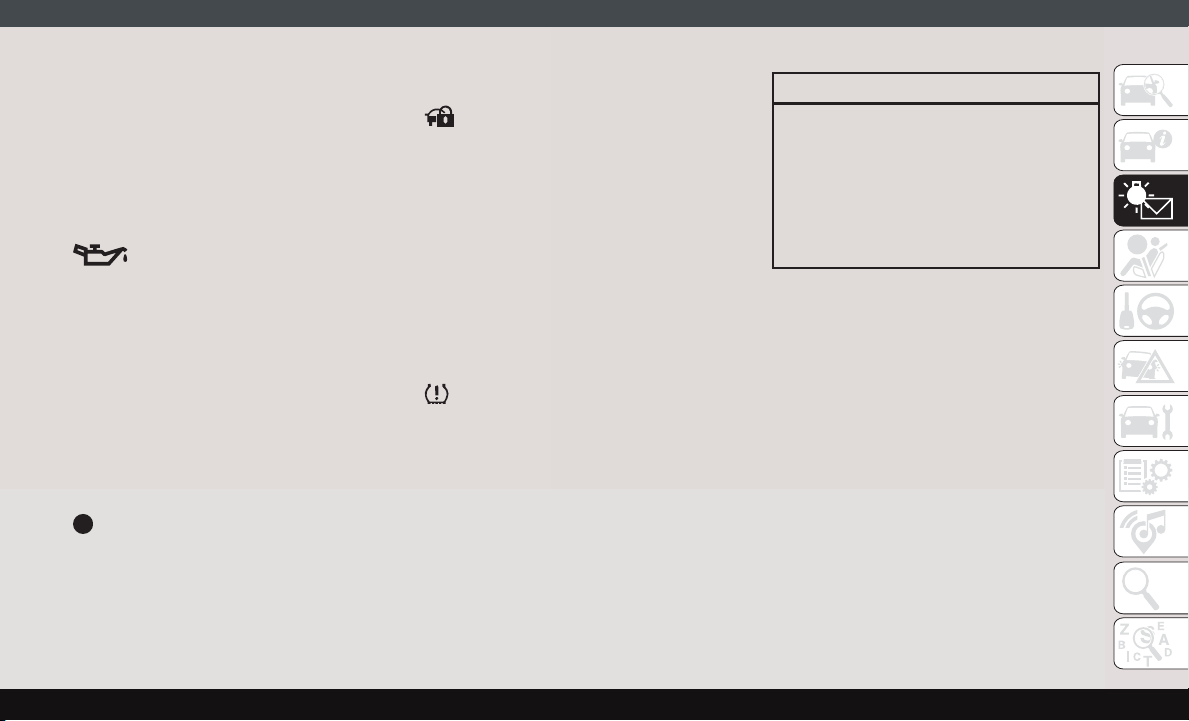
— Oil Pressure Warning Light
This warning light will illuminate to indicate
low engine oil pressure. If the light turns on
while driving, stop the vehicle, shut off the
engine as soon as possible, and contact an
authorized dealer. A chime will sound when
this light turns on.
Do not operate the vehicle until the cause is
corrected. This light does not indicate how
much oil is in the engine. The engine oil level
must be checked under the hood.
— Vehicle Security Warning Light — If
Equipped
This light will flash at a fast rate for approximately 15 seconds when the vehicle security
alarm is arming, and then will flash slowly
until the vehicle is disarmed.
Yellow Warning Lights
— Immobilizer Fail / VPS Electrical
Alarm Indicator Light
This telltale will illuminate when the vehicle
security alarm system has detected an attempt to break into the vehicle.
NOTE:
After cycling the ignition to the ON/RUN
position, the Vehicle Security Warning Light
could illuminate if a problem with the system
is detected. This condition will result in the
engine being shut off after two seconds.
— Tire Pressure Monitoring System
(TPMS) Warning Light
The warning light switches on and a message
is displayed to indicate that the tire pressure
is lower than the recommended value and/or
that slow pressure loss is occurring. In these
cases, optimal tire duration and fuel consumption may not be guaranteed.
Should one or more tires be in the condition
mentioned above, the display will show the
indications corresponding to each tire.
CAUTION!
Do not continue driving with one or more
flat tires as handling may be compromised. Stop the vehicle, avoiding sharp
braking and steering. If a tire puncture
occurs, repair immediately using the dedicated tire repair kit and contact an authorized dealer as soon as possible.
Each tire, including the spare (if provided),
should be checked monthly when cold and
inflated to the inflation pressure recommended by the vehicle manufacturer on the
vehicle placard or tire inflation pressure label. (If your vehicle has tires of a different
size than the size indicated on the vehicle
placard or tire inflation pressure label, you
should determine the proper tire inflation
pressure for those tires.)
As an added safety feature, your vehicle has
been equipped with a Tire Pressure Monitoring System (TPMS) that illuminates a low tire
pressure telltale when one or more of your
tires is significantly under-inflated. Accordingly, when the low tire pressure telltale illuminates, you should stop and check your tires
35
Page 38
as soon as possible, and inflate them to the
proper pressure. Driving on a significantly
under-inflated tire causes the tire to overheat
and can lead to tire failure. Under-inflation
also reduces fuel efficiency and tire tread
life, and may affect the vehicle’s handling
and stopping ability.
Please note that the TPMS is not a substitute
for proper tire maintenance, and it is the
driver’s responsibility to maintain correct tire
pressure, even if under-inflation has not
reached the level to trigger illumination of the
TPMS low tire pressure telltale.
Your vehicle has also been equipped with a
TPMS malfunction indicator to indicate when
the system is not operating properly. The
TPMS malfunction indicator is combined
with the low tire pressure telltale. When the
system detects a malfunction, the telltale will
flash for approximately one minute and then
remain continuously illuminated. This sequence will continue upon subsequent vehicle start-ups as long as the malfunction
GETTING TO KNOW YOUR INSTRUMENT PANEL
exists. When the malfunction indicator is
illuminated, the system may not be able to
detect or signal low tire pressure as intended.
36
TPMS malfunctions may occur for a variety of
reasons, including the installation of replacement or alternate tires or wheels on the vehicle that prevent the TPMS from functioning
properly. Always check the TPMS malfunction telltale after replacing one or more tires
or wheels on your vehicle to ensure that the
replacement or alternate tires and wheels
allow the TPMS to continue to function
properly.
CAUTION!
The TPMS has been optimized for the
original equipment tires and wheels.
TPMS pressures and warning have been
established for the tire size equipped on
your vehicle. Undesirable system operation or sensor damage may result when
using replacement equipment that is not
of the same size, type, and/or style. Aftermarket wheels can cause sensor damage.
Using aftermarket tire sealants may cause
the Tire Pressure Monitoring System
(TPMS) sensor to become inoperable. After using an aftermarket tire sealant it is
recommended that you take your vehicle
CAUTION!
to your authorized dealer to have your
sensor function checked.
— Electronic Stability Control (ESC)
Warning Light
The “ESC Indicator Light” in the instrument
cluster will come on when the ignition is
placed in the ON/RUN or MAR (ACC/ON/
RUN) position, and when ESC is activated. It
should turn off with the engine running. If the
“ESC Indicator Light” comes on continuously
with the engine running, a malfunction has
been detected in the ESC system. If this light
remains on after several ignition cycles, and
the vehicle has been driven several miles
(kilometers) at speeds greater than 30 mph
(48 km/h), see your authorized dealer as soon
as possible to have the problem diagnosed
and corrected.
• The “ESC Off Indicator Light” and the
“ESC Indicator Light” come on momentarily each time the ignition is placed in the
ON/RUN or MAR (ACC/ON/RUN) position.
Page 39
• Each time the ignition is turned to ON/RUN
or MAR (ACC/ON/RUN), the ESC system
will be on, even if it was turned off previously.
• The ESC system will make buzzing or clicking sounds when it is active. This is normal;
the sounds will stop when ESC becomes
inactive.
• This light will come on when the vehicle is
in an ESC event.
— Electronic Stability Control (ESC)
Off Warning Light
This light indicates the Electronic Stability
Control (ESC) is off.
Each time the ignition is turned to ON/RUN
or ACC/ON/RUN, the ESC system will be on,
even if it was turned off previously.
— Engine Check/Malfunction Indica-
tor Warning Light (MIL)
The Engine Check/Malfunction Indicator
Light (MIL) is a part of an Onboard Diagnostic
System called OBD II that monitors engine
and automatic transmission control systems.
This warning light will illuminate when the
ignition is in the ON/RUN position before
engine start. If the bulb does not come on
when turning the ignition switch from OFF to
ON/RUN, have the condition checked
promptly.
Certain conditions, such as a loose or missing
gas cap, poor quality fuel, etc., may illuminate the light after engine start. The vehicle
should be serviced if the light stays on
through several typical driving styles. In most
situations, the vehicle will drive normally and
will not require towing.
When the engine is running, the MIL may
flash to alert serious conditions that could
lead to immediate loss of power or severe
catalytic converter damage. The vehicle
should be serviced by an authorized dealer as
soon as possible if this occurs.
WARNING!
A malfunctioning catalytic converter, as
referenced above, can reach higher temperatures than in normal operating conditions. This can cause a fire if you drive
slowly or park over flammable substances
WARNING!
such as dry plants, wood, cardboard, etc.
This could result in death or serious injury
to the driver, occupants or others.
CAUTION!
Prolonged driving with the Malfunction
Indicator Light (MIL) on could cause damage to the vehicle control system. It also
could affect fuel economy and driveability.
If the MIL is flashing, severe catalytic
converter damage and power loss will soon
occur. Immediate service is required.
— Anti-Lock Brake (ABS) Warning
Light
This light monitors the Anti-Lock Brake System (ABS). The light will turn on when the
ignition is placed in the ON/RUN or MAR/ON/
RUN position and may stay on for as long as
four seconds.
If the ABS light remains on or turns on while
driving, then the Anti-Lock portion of the
brake system is not functioning and service is
37
Page 40

required. However, the conventional brake
system will continue to operate normally if
the brake warning light is not on.
If the ABS light is on, the brake system
should be serviced as soon as possible to
restore the benefits of Anti-Lock Brakes. If
the ABS light does not turn on when the
ignition is placed in the ON/RUN or MAR/ON/
RUN position, have the light inspected by an
authorized dealer.
— Generic Warning Light
The Generic Warning Light will illuminate if
any of the following conditions occur: Engine
Oil Pressure Sensor Failure, External Light
Failure, Fuel Cut-Off intervention or fail,
Parking Sensor Failure, DST System Failure.
The telltale will remain on fixed in case of
swivel seat failure and on blinking in case of
Air Bag Warning Light Failure. Contact an
authorized dealer immediately for service.
GETTING TO KNOW YOUR INSTRUMENT PANEL
Yellow Indicator Lights
— Stop Light Failure Indicator Light
This light will illuminate if one or more of the
stop light bulb fails.
The failure relating to this light could be:
• One or more blown bulbs.
• A blown protection fuse.
• A break in the electrical connection.
— External Light Failure Indicator
Light — If Equipped
The External Light Failure Indicator will
come on when a failure to one of the following
lights is detected:
• Direction Indicators
• Backup Lights
• Parking Lights
• Daytime Running Lights
• Clearance Lights
• License Plate Lights
The failure relating to these lights could be:
• One or more blown bulbs
• A blown protection fuse
• A break in the electrical connection
— TOW/HAUL Indicator Light
This indicator light will illuminate when
TOW/HAUL mode is selected.
Green Indicator Lights
— Turn Signal Indicator Lights
The turn signal arrows will flash independently when left or right turn signals are
selected. Turn signals can be activated when
the multifunction lever is moved down (left)
or up (right).
NOTE:
Check for an inoperative outside light bulb if
either indicator flashes at a rapid rate.
38
Page 41
— Front Fog Indicator Light — If
Equipped
This indicator light will illuminate when the
front fog lights are on.
— Park/Headlight On Indicator Light
This indicator light will illuminate when the
park lights or headlights are turned on.
— Cruise Control Indicator Light — If
Equipped
This indicator light will illuminate when the
cruise control is activated.
NOTE:
There will be no change in the indicator light
when the desired speed is set.
Refer to “Speed Control” in “Starting And
Operating” for further information.
Blue Indicator Lights
— High Beam Indicator Light
This indicator light will illuminate to indicate
that the high beam headlights are on. With
the low beams activated, push the multifunction lever forward (toward the front of the
vehicle) to turn on the high beams. Pull the
multifunction lever rearward (toward the rear
of the vehicle) to turn off the high beams. If
the high beams are off, pull the lever toward
you for a temporary high beam on, "flash to
pass" scenario.
ONBOARD DIAGNOSTIC SYSTEM — OBD II
Your vehicle is equipped with a sophisticated
Onboard Diagnostic system called OBD II.
This system monitors the performance of the
emissions, engine, and transmission control
systems. When these systems are operating
properly, your vehicle will provide excellent
performance and fuel economy, as well as
engine emissions well within current government regulations.
If any of these systems require service, the
OBD II system will turn on the Malfunction
Indicator Light (MIL). It will also store diagnostic codes and other information to assist
your service technician in making repairs.
Although your vehicle will usually be drivable
and not need towing, see an authorized
dealer for service as soon as possible.
CAUTION!
• Prolonged driving with the MIL on could
cause further damage to the emission
control system. It could also affect fuel
economy and driveability. The vehicle
must be serviced before any emissions
tests can be performed.
• If the MIL is flashing while the vehicle is
running, severe catalytic converter damage and power loss will soon occur. Immediate service is required.
39
Page 42

Onboard Diagnostic System
(OBD II) Cybersecurity
Your vehicle is required to have an Onboard
Diagnostic system (OBD II) and a connection
port to allow access to information related to
the performance of your emissions controls.
Authorized service technicians may need to
access this information to assist with the
diagnosis and service of your vehicle and
emissions system.
WARNING!
• ONLY an authorized service technician
should connect equipment to the OBD II
GETTING TO KNOW YOUR INSTRUMENT PANEL
WARNING!
connection port in order to read the VIN,
diagnose, or service your vehicle.
• If unauthorized equipment is connected
to the OBD II connection port, such as a
driver-behavior tracking device, it may:
• Be possible that vehicle systems,
including safety related systems,
could be impaired or a loss of vehicle control could occur that may
result in an accident involving serious injury or death.
WARNING!
• Access, or allow others to access,
information stored in your vehicle
systems, including personal information.
For further information, refer to “Cybersecurity” in “Multimedia”.
40
Page 43
AUXILIARY DRIVING SYSTEMS
Tire Pressure Monitoring System
(TPMS)
The Tire Pressure Monitor System (TPMS)
will warn the driver of a low tire pressure
based on the vehicle recommended cold
placard pressure.
The tire pressure will vary with temperature
by about 1 psi (7 kPa) for every 12°F (6.5°C).
This means that when the outside temperature decreases, the tire pressure will decrease. Tire pressure should always be set
based on cold inflation tire pressure. This is
defined as the tire pressure after the vehicle
has not been driven for at least three hours, or
driven less than 1 mile (1.6 km) after a three
hour period. The cold tire inflation pressure
must not exceed the maximum inflation pressure molded into the tire sidewall. Refer to
“Tires” in “Servicing And Maintenance” for
information on how to properly inflate the
vehicle’s tires. The tire pressure will also
increase as the vehicle is driven - this is
normal and there should be no adjustment for
this increased pressure.
The TPMS will warn the driver of a low tire
pressure if the tire pressure falls below the
low-pressure warning limit for any reason,
including low temperature effects and natural pressure loss through the tire.
The TPMS will continue to warn the driver of
low tire pressure as long as the condition
exists, and will not turn off until the tire
pressure is at or above the recommended
cold placard pressure. Once the low tire pressure warning (TPMS Warning Light) illuminates, you must increase the tire pressure to
the recommended cold placard pressure in
order for the TPMS Warning Light to turn off.
The system will automatically update and the
TPMS Warning Light will turn off once the
system receives the updated tire pressures.
The vehicle may need to be driven for up to
20 minutes above 15 mph (24 km/h) in order
for the TPMS to receive this information.
NOTE:
When filling warm tires, the tire pressure may
need to be increased up to an additional 4 psi
(28 kPa) above the recommended cold placard pressure in order to turn the TPMS Warning Light off.
For example, your vehicle may have a recommended cold (parked for more than three
hours) placard pressure of 30 psi (207 kPa).
If the ambient temperature is 68°F (20°C)
and the measured tire pressure is 27 psi
(186 kPa), a temperature drop to 20°F (-7°C)
will decrease the tire pressure to approximately 23 psi (158 kPa). This tire pressure is
sufficiently low enough to turn on the TPMS
Warning Light. Driving the vehicle may cause
the tire pressure to rise to approximately
27 psi (186 kPa), but the TPMS Warning
Light will still be on. In this situation, the
TPMS Warning Light will turn off only after
the tires are inflated to the vehicle’s recommended cold placard pressure value.
CAUTION!
• The TPMS has been optimized for the
original equipment tires and wheels.
TPMS pressures and warning have been
established for the tire size equipped on
your vehicle. Undesirable system operation or sensor damage may result when
using replacement equipment that is not
of the same size, type, and/or style.
41
Page 44
CAUTION!
Aftermarket wheels can cause sensor
damage.
SAFETY
• Using aftermarket tire sealants may
cause the Tire Pressure Monitoring System (TPMS) sensor to become inoperable. After using an aftermarket tire
sealant it is recommended that you take
your vehicle to an authorized dealership
to have your sensor function checked.
• After inspecting or adjusting the tire
pressure always reinstall the valve stem
cap. This will prevent moisture and dirt
from entering the valve stem, which
could damage the TPMS sensor.
NOTE:
• The TPMS is not intended to replace normal tire care and maintenance or to provide
warning of a tire failure or condition.
• The TPMS should not be used as a tire
pressure gauge while adjusting your tire
pressure.
42
• Driving on a significantly under-inflated tire
causes the tire to overheat and can lead to
tire failure. Under-inflation also reduces
fuel efficiency and tire tread life, and may
affect the vehicle’s handling and stopping
ability.
• The TPMS is not a substitute for proper tire
maintenance, and it is the driver’s responsibility to maintain correct tire pressure
using an accurate tire pressure gauge, even
if under-inflation has not reached the level
to trigger illumination of the TPMS Warning
Light.
• Seasonal temperature changes will affect
tire pressure, and the TPMS will monitor
the actual tire pressure in the tire.
Base System
This is the TPMS warning indicator located in the instrument
cluster.
The TPMS uses wireless technology with
wheel rim mounted electronic sensors to
monitor tire pressure levels. Sensors,
mounted to each wheel as part of the valve
stem, transmit tire pressure readings to the
Receiver Module.
NOTE:
It is particularly important for you to check
the tire pressure in all of the tires on your
vehicle regularly and to maintain the proper
pressure.
The TPMS consists of the following components:
• Receiver Module.
• Four Tire Pressure Monitoring Sensors.
• Tire Pressure Monitoring System Warning
Light.
Tire Pressure Monitoring Low Pressure
Warnings
The Tire Pressure Monitoring System Warning
Light will illuminate in the instrument cluster, an audible chime will be activated, and
the “Check tire pressure” text message will
display when one or more of the four active
Page 45

road tire pressures are low. Should this occur,
you should stop as soon as possible, check
the inflation pressure of each tire on your
vehicle, and inflate each tire to the vehicle’s
recommended cold placard pressure value.
The system will automatically update and the
Tire Pressure Monitoring Light will extinguish
once the updated tire pressures have been
received. The vehicle may need to be driven
for up to 20 minutes above 15 mph
(24 km/h) to receive this information.
Check TPMS Warnings
The Tire Pressure Monitoring System Warning
Light will flash on and off for 75 seconds and
remain on solid when a system fault is detected, an audible chime will be activated
and the “Tire Pressure Monitoring Unavailable” text message will display. If the ignition
key is cycled, this sequence will repeat providing the system fault still exists. The TPMS
Warning Light will turn off when the fault
condition no longer exists. A system fault can
occur with any of the following scenarios:
1. Jamming due to electronic devices or driving next to facilities emitting the same
radio frequencies as the TPM sensors.
2. Installing some form of aftermarket window tinting that affects radio wave
signals.
3. Snow or ice around the wheels or wheel
housings.
4. Using tire chains on the vehicle.
5. Using wheels/tires not equipped with TPM
sensors.
NOTE:
Your vehicle is equipped with a regular size
spare wheel.
1. The spare tire has a tire pressure monitoring sensor, but it is not monitored until it
is mounted in place of any of the existing
four road tires.
2. If you install the spare tire in place of a
road tire that has a pressure below the
low-pressure warning limit, upon the next
ignition key cycle, a chime will sound and
the TPMS Warning Light will turn ON due
to the low tire condition. Then, after driving the vehicle for up to 20 minutes above
15 mph (24 km/h), the system will recognize the new sensor, and turn off the
telltale.
3. If a spare tire not equipped with tire
pressure monitoring sensor is used, then
the TPMS Warning Light will turn ON,
flashing for 75 seconds and then remaining solid for each subsequent ignition key
cycle.
NOTE:
For correct Tire Pressure Monitoring behavior,
please wait for about 20 minutes in key-off
during each tire substitution.
General Information
This device complies with Part 15 of the FCC
rules and RSS 210 of Industry Canada. Operation is subject to the following conditions:
1. This device may not cause harmful
interference.
2. This device must accept any interference
received, including interference that may
cause undesired operation.
NOTE:
Changes or modifications not expressly approved by the party responsible for compliance could void the user’s authority to operate the equipment.
43
Page 46

OCCUPANT RESTRAINT SYSTEMS
Some of the most important safety features in
your vehicle are the restraint systems:
SAFETY
Occupant Restraint Systems
Features
• Seat Belt Systems
• Supplemental Restraint Systems (SRS) Air
Bags
• Child Restraints
Some of the safety features described in this
section may be standard equipment on some
models, or may be optional equipment on
others. If you are not sure, ask an authorized
dealer.
Important Safety Precautions
Please pay close attention to the information
in this section. It tells you how to use your
restraint system properly, to keep you and
your passengers as safe as possible.
Here are some simple steps you can take to
minimize the risk of harm from a deploying
air bag:
1. Children 12 years old and under should
always ride buckled up in the rear seat of
a vehicle with a rear seat.
2. A child who is not big enough to wear the
vehicle seat belt properly (Refer to “Child
Restraints” in this section for further information) must be secured in the appropriate child restraint or belt-positioning
booster seat in a rear seating position.
3. If a child from 2 to 12 years old (not in a
rear-facing child restraint) must ride in
the front passenger seat, move the seat as
far back as possible and use the proper
child restraint (Refer to “Child Restraints” in this section for further
information).
4. Never allow children to slide the shoulder
belt behind them or under their arm.
5. You should read the instructions provided
with your child restraint to make sure that
you are using it properly.
6. All occupants should always wear their lap
and shoulder belts properly.
7. The driver and front passenger seats
should be moved back as far as practical
to allow the front air bags room to inflate.
8. Do not lean against the door or window. If
your vehicle has side air bags, and deployment occurs, the side air bags will inflate
forcefully into the space between occupants and the door and occupants could
be injured.
9. If the air bag system in this vehicle needs
to be modified to accommodate a disabled person, refer to the “Customer Assistance” section for customer service
contact information.
WARNING!
• Never place a rear-facing child restraint
in front of an air bag. A deploying passenger front air bag can cause death or
serious injury to a child 12 years or
younger, including a child in a rearfacing child restraint.
44
Page 47
WARNING!
• Never install a rear-facing child restraint
in the front seat of a vehicle. Only use a
rear-facing child restraint in the rear
seat. If the vehicle does not have a rear
seat, do not transport a rear-facing child
restraint in that vehicle.
Seat Belt Systems
Buckle up even though you are an excellent
driver, even on short trips. Someone on the
road may be a poor driver and could cause a
collision that includes you. This can happen
far away from home or on your own street.
Research has shown that seat belts save
lives, and they can reduce the seriousness of
injuries in a collision. Some of the worst
injuries happen when people are thrown from
the vehicle. Seat belts reduce the possibility
of ejection and the risk of injury caused by
striking the inside of the vehicle. Everyone in
a motor vehicle should be belted at all times.
Enhanced Seat Belt Use Reminder System
(BeltAlert)
Driver and Passenger BeltAlert — If Equipped
BeltAlert is a feature intended to remind
the driver and outboard front seat passenger
(if equipped with outboard front passenger
seat BeltAlert) to buckle their seat belts. The
Belt Alert feature is active whenever the ignition switch is in the AVV/START or MAR/RUN
position.
Initial Indication
If the driver is unbuckled when the ignition
switch is first in the AVV/START or MAR/RUN
position, a chime will signal for a few seconds. If the driver or outboard front seat
passenger (if equipped with outboard front
passenger seat BeltAlert) is unbuckled when
the ignition switch is first in the AVV/START
or MAR/RUN position the Seat Belt Reminder
Light will turn on and remain on until both
outboard front seat belts are buckled. The
outboard front passenger seat BeltAlert is not
active when an outboard front passenger seat
is unoccupied.
BeltAlert Warning Sequence
The BeltAlert warning sequence is activated
when the vehicle is moving above a specified
vehicle speed range and the driver or outboard front seat passenger is unbuckled (if
equipped with outboard front passenger seat
BeltAlert) (the outboard front passenger seat
BeltAlert is not active when the outboard
front passenger seat is unoccupied). The
BeltAlert warning sequence starts by blinking
the Seat Belt Reminder Light and sounding
an intermittent chime. Once the BeltAlert
warning sequence has completed, the Seat
Belt Reminder Light will remain on until the
seat belts are buckled. The BeltAlert warning
sequence may repeat based on vehicle speed
until the driver and occupied outboard front
seat passenger seat belts are buckled. The
driver should instruct all occupants to buckle
their seat belts.
45
Page 48
Change of Status
If the driver or outboard front seat passenger
(if equipped with outboard front passenger
SAFETY
seat BeltAlert) unbuckles their seat belt
while the vehicle is traveling, the BeltAlert
warning sequence will begin until the seat
belts are buckled again.
The outboard front passenger seat BeltAlert
is not active when the outboard front passenger seat is unoccupied. BeltAlert may be
triggered when an animal or other items are
placed on the outboard front passenger seat
or when the seat is folded flat (if equipped). It
is recommended that pets be restrained in
the rear seat (if equipped) in pet harnesses or
pet carriers that are secured by seat belts,
and cargo is properly stowed.
BeltAlert can be activated or deactivated by
an authorized dealer. FCA US LLC does not
recommend deactivating BeltAlert.
NOTE:
If BeltAlert has been deactivated and the
driver or outboard front seat passenger (if
equipped with outboard front passenger seat
BeltAlert) is unbuckled the Seat Belt Reminder Light will turn on and remain on until
the driver and outboard front seat passenger
seat belts are buckled.
Lap/Shoulder Belts
All seating positions in your vehicle are
equipped with lap/shoulder belts.
The seat belt webbing retractor will lock only
during very sudden stops or collisions. This
feature allows the shoulder part of the seat
belt to move freely with you under normal
conditions. However, in a collision the seat
belt will lock and reduce your risk of striking
the inside of the vehicle or being thrown out
of the vehicle.
WARNING!
• Relying on the air bags alone could lead
to more severe injuries in a collision. The
air bags work with your seat belt to
WARNING!
restrain you properly. In some collisions,
the air bags won’t deploy at all. Always
wear your seat belt even though you have
air bags.
• In a collision, you and your passengers
can suffer much greater injuries if you
are not properly buckled up. You can
strike the interior of your vehicle or other
passengers, or you can be thrown out of
the vehicle. Always be sure you and
others in your vehicle are buckled up
properly.
• It is dangerous to ride in a cargo area,
inside or outside of a vehicle. In a collision, people riding in these areas are
more likely to be seriously injured or
killed.
• Do not allow people to ride in any area of
your vehicle that is not equipped with
seats and seat belts.
• Be sure everyone in your vehicle is in a
seat and using a seat belt properly. Occupants, including the driver, should always wear their seat belts whether or not
an air bag is also provided at their seat-
46
Page 49
WARNING!
ing position to minimize the risk of severe injury or death in the event of a
crash.
• Wearing your seat belt incorrectly could
make your injuries in a collision much
worse. You might suffer internal injuries,
or you could even slide out of the seat
belt. Follow these instructions to wear
your seat belt safely and to keep your
passengers safe, too.
• Two people should never be belted into a
single seat belt. People belted together
can crash into one another in a collision,
hurting one another badly. Never use a
lap/shoulder belt or a lap belt for more
than one person, no matter what their
size.
WARNING!
• A lap belt worn too high can increase the
risk of injury in a collision. The seat belt
forces won’t be at the strong hip and
pelvic bones, but across your abdomen.
WARNING!
Always wear the lap part of your seat belt
as low as possible and keep it snug.
• A twisted seat belt may not protect you
properly. In a collision, it could even cut
into you. Be sure the seat belt is flat
against your body, without twists. If you
can’t straighten a seat belt in your vehicle, take it to an authorized dealer
immediately and have it fixed.
• A seat belt that is buckled into the wrong
buckle will not protect you properly. The
lap portion could ride too high on your
body, possibly causing internal injuries.
Always buckle your seat belt into the
buckle nearest you.
• A seat belt that is too loose will not
protect you properly. In a sudden stop,
you could move too far forward, increasing the possibility of injury. Wear your
seat belt snugly.
• A seat belt that is worn under your arm is
dangerous. Your body could strike the
inside surfaces of the vehicle in a collision, increasing head and neck injury. A
seat belt worn under the arm can cause
WARNING!
internal injuries. Ribs aren’t as strong as
shoulder bones. Wear the seat belt over
your shoulder so that your strongest
bones will take the force in a collision.
• A shoulder belt placed behind you will
not protect you from injury during a
collision. You are more likely to hit your
head in a collision if you do not wear your
shoulder belt. The lap and shoulder belt
are meant to be used together.
• A frayed or torn seat belt could rip apart
in a collision and leave you with no
protection. Inspect the seat belt system
periodically, checking for cuts, frays, or
loose parts. Damaged parts must be replaced immediately. Do not disassemble
or modify the seat belt system. Seat belt
assemblies must be replaced after a collision.
Lap/Shoulder Belt Operating Instructions
1. Enter the vehicle and close the door. Sit
back and adjust the seat.
47
Page 50
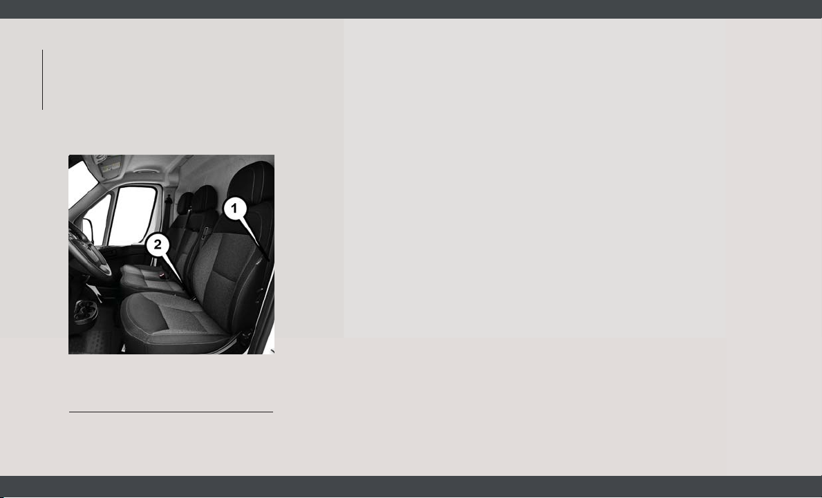
2. The seat belt latch plate is above the back
of the front seat, and next to your arm in
the rear seat (for vehicles equipped with a
rear seat). Grasp the latch plate and pull
SAFETY
out the seat belt. Slide the latch plate up
the webbing as far as necessary to allow
the seat belt to go around your lap.
Pulling Out The Latch Plate
1 — Seat Belt Latch Plate
2 — Seat Belt Buckle
48
3. When the seat belt is long enough to fit,
insert the latch plate into the buckle until
you hear a “click.”
4. Position the lap belt so that it is snug and
lies low across your hips, below your abdomen. To remove slack in the lap belt
portion, pull up on the shoulder belt. To
loosen the lap belt if it is too tight, tilt the
latch plate and pull on the lap belt. A snug
seat belt reduces the risk of sliding under
the seat belt in a collision.
5. Position the shoulder belt across the
shoulder and chest with minimal, if any
slack so that it is comfortable and not
resting on your neck. The retractor will
withdraw any slack in the shoulder belt.
6. To release the seat belt, push the red
button on the buckle. The seat belt will
automatically retract to its stowed position. If necessary, slide the latch plate
down the webbing to allow the seat belt to
retract fully.
Lap/Shoulder Belt Untwisting Procedure
Use the following procedure to untwist a
twisted lap/shoulder belt.
1. Position the latch plate as close as possible to the anchor point.
2. At about 6 to 12 inches (15 to 30 cm)
above the latch plate, grasp and twist the
seat belt webbing 180 degrees to create a
fold that begins immediately above the
latch plate.
3. Slide the latch plate upward over the
folded webbing. The folded webbing must
enter the slot at the top of the latch plate.
4. Continue to slide the latch plate up until it
clears the folded webbing and the seat
belt is no longer twisted.
Adjustable Upper Shoulder Belt Anchorage
In the driver and outboard front passenger
seats, the top of the shoulder belt can be
adjusted upward or downward to position the
seat belt away from your neck. Push or
squeeze the anchorage button to release the
anchorage, and move it up or down to the
position that serves you best.
Page 51
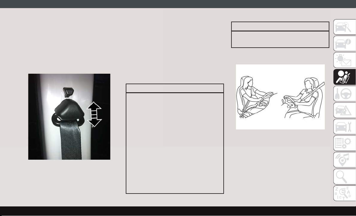
As a guide, if you are shorter than average,
you will prefer the shoulder belt anchorage in
a lower position, and if you are taller than
average, you will prefer the shoulder belt
anchorage in a higher position. After you
release the anchorage button, try to move it
up or down to make sure that it is locked in
position.
Adjustable Anchorage
NOTE:
The adjustable upper shoulder belt anchorage is equipped with an Easy Up feature. This
feature allows the shoulder belt anchorage to
be adjusted in the upward position without
pushing or squeezing the release button. To
verify the shoulder belt anchorage is latched,
pull downward on the shoulder belt anchorage until it is locked into position.
WARNING!
• Wearing your seat belt incorrectly could
make your injuries in a collision much
worse. You might suffer internal injuries,
or you could even slide out of the seat
belt. Follow these instructions to wear
your seat belt safely and to keep your
passengers safe, too.
• Position the shoulder belt across the
shoulder and chest with minimal, if any
slack so that it is comfortable and not
resting on your neck. The retractor will
withdraw any slack in the shoulder belt.
• Misadjustment of the seat belt could
reduce the effectiveness of the safety
belt in a crash.
WARNING!
• Always make all seat belt height adjustments when the vehicle is stationary.
Seat Belts And Pregnant Women
Pregnant Women And Seat Belts
Seat belts must be worn by all occupants
including pregnant women: the risk of injury
in the event of an accident is reduced for the
mother and the unborn child if they are wearing a seat belt.
Position the lap belt snug and low below the
abdomen and across the strong bones of the
hips. Place the shoulder belt across the chest
49
Page 52
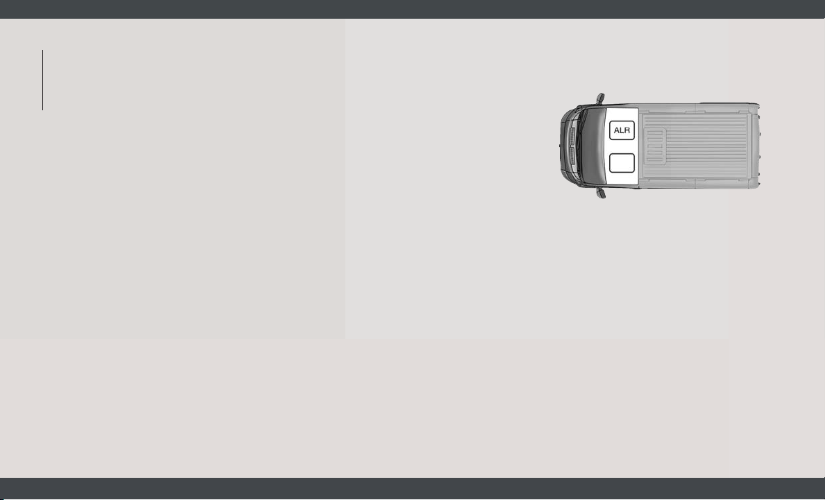
and away from the neck. Never place the
shoulder belt behind the back or under the
arm.
SAFETY
Seat Belt Pretensioner
The front seat belt system is equipped with
pretensioning devices that are designed to
remove slack from the seat belt in the event
of a collision. These devices may improve the
performance of the seat belt by removing
slack from the seat belt early in a collision.
Pretensioners work for all size occupants,
including those in child restraints.
NOTE:
These devices are not a substitute for proper
seat belt placement by the occupant. The
seat belt still must be worn snugly and positioned properly.
The pretensioners are triggered by the Occupant Restraint Controller (ORC). Like the air
bags, the pretensioners are single use items.
A deployed pretensioner or a deployed air bag
must be replaced immediately.
Energy Management Feature
The front seat belt system is equipped with
an Energy Management feature that may help
further reduce the risk of injury in the event
of a collision. The seat belt system has a
retractor assembly that is designed to release
webbing in a controlled manner.
Switchable Automatic Locking Retractor
(ALR)
The seat belt in the passenger seating position is equipped with a Switchable Automatic
Locking Retractor (ALR) which is used to
secure a child restraint system. For additional information, refer to “Installing Child
Restraints Using The Vehicle Seat Belt” under the “Child Restraints” section of this
manual. The figure below illustrates the locking feature for each seating position.
Front Bucket Seat: ALR — Switchable
Automatic Locking Retractor
50
Page 53
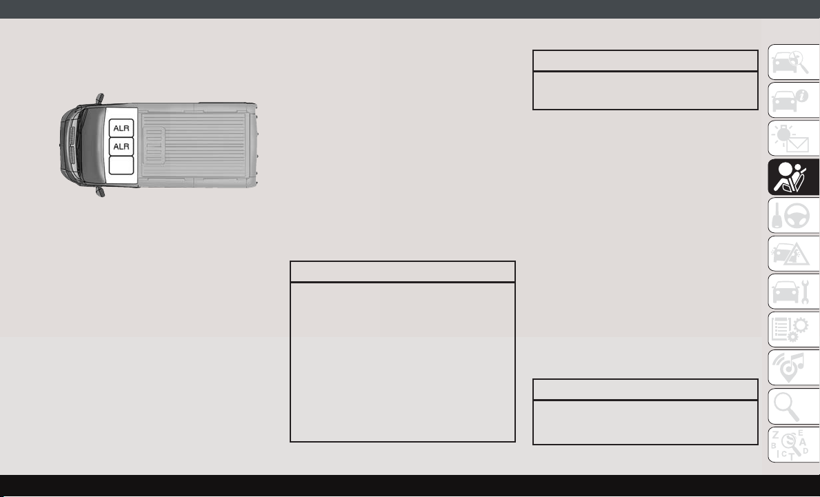
Front Bench Seat: ALR — Switchable
Automatic Locking Retractor
If the passenger seating position is equipped
with an ALR and is being used for normal
usage, only pull the seat belt webbing out far
enough to comfortably wrap around the occupant’s mid-section so as to not activate the
ALR. If the ALR is activated, you will hear a
clicking sound as the seat belt retracts. Allow
the webbing to retract completely in this case
and then carefully pull out only the amount of
webbing necessary to comfortably wrap
around the occupant’s mid-section. Slide the
latch plate into the buckle until you hear a
"click."
In Automatic Locking Mode, the shoulder
belt is automatically pre-locked. The seat
belt will still retract to remove any slack in the
shoulder belt. Use the Automatic Locking
Mode anytime a child restraint is installed in
a seating position that has a seat belt with
this feature. Children 12 years old and under
should always be properly restrained in the
rear seat of a vehicle with a rear seat.
WARNING!
• Never place a rear-facing child restraint
in front of an air bag. A deploying passenger front air bag can cause death or
serious injury to a child 12 years or
younger, including a child in a rearfacing child restraint.
• Never install a rear-facing child restraint
in the front seat of a vehicle. Only use a
rear-facing child restraint in the rear
seat. If the vehicle does not have a rear
WARNING!
seat, do not transport a rear-facing child
restraint in that vehicle.
How To Engage The Automatic Locking Mode
1. Buckle the combination lap and shoulder
belt.
2. Grasp the shoulder portion and pull downward until the entire seat belt is extracted.
3. Allow the seat belt to retract. As the seat
belt retracts, you will hear a clicking
sound. This indicates the seat belt is now
in the Automatic Locking Mode.
How To Disengage The Automatic Locking Mode
Unbuckle the combination lap/shoulder belt
and allow it to retract completely to disengage the Automatic Locking Mode and activate the vehicle sensitive (emergency) locking mode.
WARNING!
• The seat belt assembly must be replaced
if the switchable Automatic Locking Re-
51
Page 54
WARNING!
tractor (ALR) feature or any other seat
belt function is not working properly
SAFETY
when checked according to the procedures in the Service Manual.
• Failure to replace the seat belt assembly
could increase the risk of injury in collisions.
• Do not use the Automatic Locking Mode
to restrain occupants who are wearing
the seat belt or children who are using
booster seats. The locked mode is only
used to install rear-facing or forwardfacing child restraints that have a harness for restraining the child.
Supplemental Restraint Systems
(SRS)
Some of the safety features described in this
section may be standard equipment on some
models, or may be optional equipment on
others. If you are not sure, ask an authorized
dealer.
52
The air bag system must be ready to protect
you in a collision. The Occupant Restraint
Controller (ORC) monitors the internal circuits and interconnecting wiring associated
with the electrical Air Bag System Components. Your vehicle may be equipped with the
following Air Bag System Components:
Air Bag System Components
• Occupant Restraint Controller (ORC)
• Air Bag Warning Light
• Steering Wheel and Column
• Instrument Panel
• Driver and Front Passenger Air Bags
• Seat Belt Buckle Switch
• Supplemental Side Air Bags
• Front and Side Impact Sensors
• Seat Belt Pretensioners
Air Bag Warning Light
The ORC monitors the readiness of the
electronic parts of the air bag system whenever the ignition switch is in the AVV/START
or MAR/ACC/ON/RUN position. If the ignition
switch is in the STOP/OFF/LOCK position the
air bag system is not on and the air bags will
not inflate.
The ORC contains a backup power supply
system that may deploy the air bag system
even if the battery loses power or it becomes
disconnected prior to deployment.
The ORC turns on the Air Bag Warning Light
in the instrument panel for approximately
four to eight seconds for a self-check when
the ignition switch is in the MAR/ACC/ON/
RUN position. After the self-check, the Air
Bag Warning Light will turn off. If the ORC
detects a malfunction in any part of the
system, it turns on the Air Bag Warning Light,
either momentarily or continuously. A single
chime will sound to alert you if the light
comes on again after initial startup.
The ORC also includes diagnostics that will
illuminate the instrument panel Air Bag
Warning Light if a malfunction is detected
that could affect the air bag system. The
diagnostics also record the nature of the
malfunction. While the air bag system is
Page 55
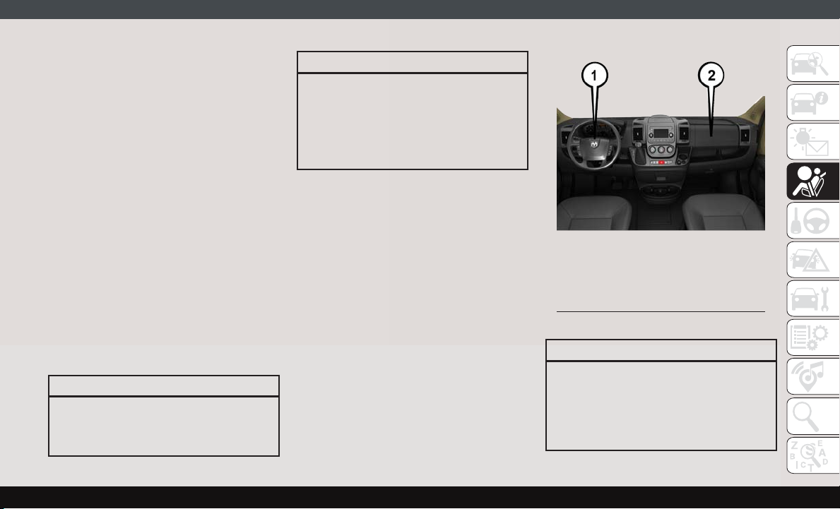
designed to be maintenance free, if any of the
following occurs, have an authorized dealer
service the air bag system immediately.
• The Air Bag Warning Light does not come
on during the four to eight seconds when
the ignition switch is first in the MAR/ACC/
ON/RUN position.
• The Air Bag Warning Light remains on after
the four to eight-second interval.
• The Air Bag Warning Light comes on intermittently or remains on while driving.
NOTE:
If the speedometer, tachometer, or any engine related gauges are not working, the Occupant Restraint Controller (ORC) may also
be disabled. In this condition the air bags
may not be ready to inflate for your protection. Have an authorized dealer service the air
bag system immediately.
WARNING!
Ignoring the Air Bag Warning Light in your
instrument panel could mean you won’t
have the air bag system to protect you in a
WARNING!
collision. If the light does not come on as a
bulb check when the ignition is first turned
on, stays on after you start the vehicle, or if
it comes on as you drive, have an authorized dealer service the air bag system
immediately.
Front Air Bags
This vehicle has front air bags and lap/
shoulder belts for both the driver and front
passenger. The front air bags are a supplement to the seat belt restraint systems. The
driver front air bag is mounted in the center of
the steering wheel. The passenger front air
bag is mounted in the instrument panel,
above the glove compartment. The words
“SRS AIRBAG” or “AIRBAG” are embossed
on the air bag covers.
Front Air Bag Locations
1 — Driver Front Air Bag
2 — Passenger Front Air Bag
WARNING!
• Being too close to the steering wheel or
instrument panel during front air bag
deployment could cause serious injury,
including death. Air bags need room to
inflate. Sit back, comfortably extending
53
Page 56
WARNING!
your arms to reach the steering wheel or
instrument panel.
SAFETY
• Never place a rear-facing child restraint
in front of an air bag. A deploying passenger front air bag can cause death or
serious injury to a child 12 years or
younger, including a child in a rearfacing child restraint.
• Never install a rear-facing child restraint
in the front seat of a vehicle. Only use a
rear-facing child restraint in the rear
seat. If the vehicle does not have a rear
seat, do not transport a rear-facing child
restraint in that vehicle.
Driver And Passenger Front Air Bag Features
The driver and passenger front air bag system
is designed to inflate based on the severity
and type of collision as determined by the
Occupant Restraint Controller (ORC), which
may receive information from the front impact sensors (if equipped) or other system
components.
WARNING!
• No objects should be placed over or near
the air bag on the instrument panel or
steering wheel because any such objects
could cause harm if the vehicle is in a
collision severe enough to cause the air
bag to inflate.
• Do not put anything on or around the air
bag covers or attempt to open them
manually. You may damage the air bags
and you could be injured because the air
bags may no longer be functional. The
protective covers for the air bag cushions are designed to open only when the
air bags are inflating.
• Relying on the air bags alone could lead
to more severe injuries in a collision. The
air bags work with your seat belt to
restrain you properly. In some collisions,
air bags won’t deploy at all. Always wear
your seat belts even though you have air
bags.
Front Air Bag Operation
Front Air Bags are designed to provide additional protection by supplementing the seat
belts. Front air bags are not expected to
reduce the risk of injury in rear, side, or
rollover collisions. The front air bags will not
deploy in all frontal collisions, including
some that may produce substantial vehicle
damage — for example, some pole collisions,
truck underrides, and angle offset collisions.
On the other hand, depending on the type
and location of impact, front air bags may
deploy in crashes with little vehicle front-end
damage but that produce a severe initial
deceleration.
Because air bag sensors measure vehicle
deceleration over time, vehicle speed and
damage by themselves are not good indicators of whether or not an air bag should have
deployed.
Seat belts are necessary for your protection in
all collisions, and also are needed to help
keep you in position, away from an inflating
air bag.
54
Page 57
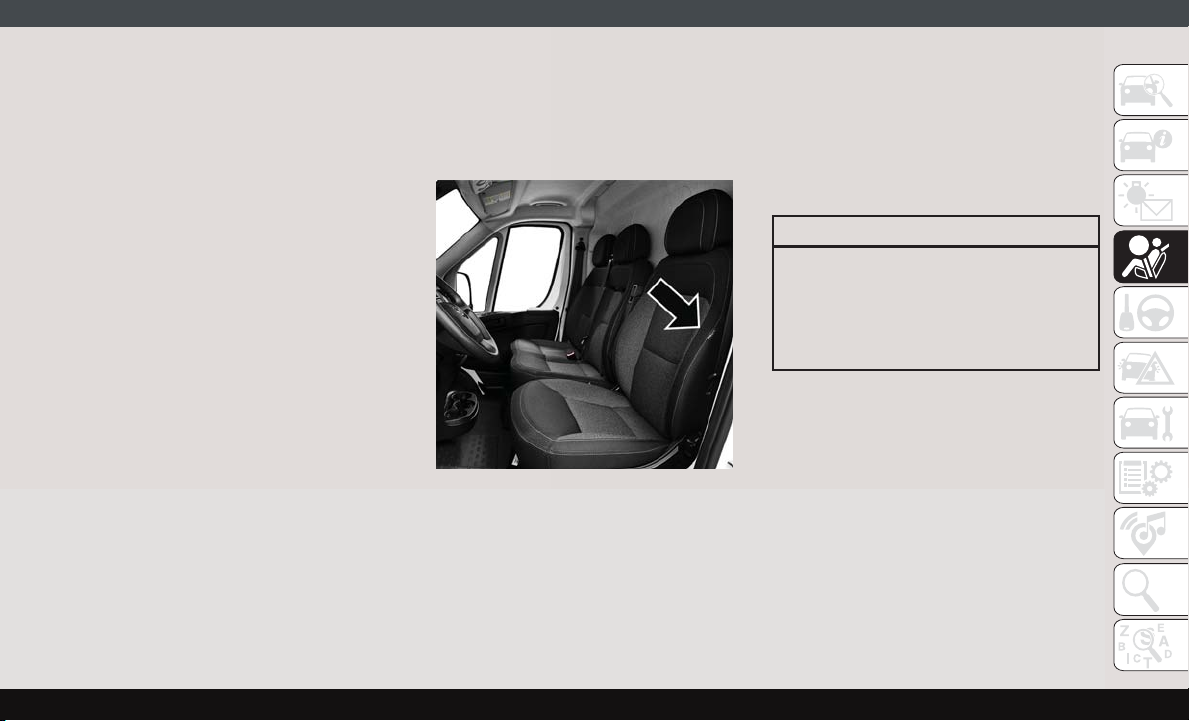
When the ORC detects a collision requiring
the front air bags, it signals the inflator units.
A large quantity of non-toxic gas is generated
to inflate the front air bags.
The steering wheel hub trim cover and the
upper passenger side of the instrument panel
separate and fold out of the way as the air
bags inflate to their full size. The front air
bags fully inflate in less time than it takes to
blink your eyes. The front air bags then
quickly deflate while helping to restrain the
driver and front passenger.
Supplemental Side Air Bags
Supplemental Seat-Mounted Side Air Bags
(SABs)
This vehicle is equipped with Supplemental
Seat-Mounted Side Air Bags (SABs).
Supplemental Seat-Mounted Side Air Bags
(SABs) are located in the outboard side of the
front seats. The SABs are marked with “SRS
AIRBAG” or “AIRBAG” on a label or on the
seat trim on the outboard side of the seats.
The SABs may help to reduce the risk of
occupant injury during certain side impacts,
in addition to the injury reduction potential
provided by the seat belts and body structure.
Front Supplemental Seat-Mounted Side
Air Bag Label
When the SAB deploys, it opens the seam on
the outboard side of the seatback’s trim
cover. The inflating SAB deploys through the
seat seam into the space between the occupant and the door. The SAB moves at a very
high speed and with such a high force that it
could injure occupants if they are not seated
properly, or if items are positioned in the area
where the SAB inflates. Children are at an
even greater risk of injury from a deploying air
bag.
WARNING!
Do not use accessory seat covers or place
objects between you and the Side Air
Bags; the performance could be adversely
affected and/or objects could be pushed
into you, causing serious injury.
Supplemental Side Air Bag Inflatable Curtains
(SABICs)
This vehicle is equipped with Supplemental
Side Air Bag Inflatable Curtains (SABICs).
Supplemental Side Air Bag Inflatable Curtains (SABICs) are located above the side
windows. The trim covering the SABICs is
labeled “SRS AIRBAG” or “AIRBAG.”
55
Page 58
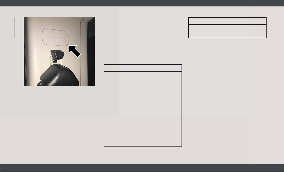
SAFETY
Supplemental Side Air Bag Inflatable
Curtain (SABIC) Label Location
SABICs may help reduce the risk of head and
other injuries to front and rear seat outboard
occupants in certain side impacts, in addition to the injury reduction potential provided
by the seat belts and body structure.
The SABIC deploys downward, covering the
side windows. An inflating SABIC pushes the
outside edge of the headliner out of the way
and covers the window. The SABICs inflate
with enough force to injure occupants if they
56
are not belted and seated properly, or if items
are positioned in the area where the SABICs
inflate. Children are at an even greater risk of
injury from a deploying air bag.
The SABICs may help reduce the risk of
partial or complete ejection of vehicle occupants through side windows in certain side
impact events.
WARNING!
• Do not mount equipment, or stack luggage or other cargo up high enough to
block the deployment of the SABICs.
The trim covering above the side windows where the SABIC and its deployment path are located should remain
free from any obstructions.
• In order for the SABICs to work as intended, do not install any accessory
items in your vehicle which could alter
the roof. Do not add an aftermarket
sunroof to your vehicle. Do not add roof
racks that require permanent attachments (bolts or screws) for installation
WARNING!
on the vehicle roof. Do not drill into the
roof of the vehicle for any reason.
Side Impacts
The Side Air Bags are designed to activate in
certain side impacts. The Occupant Restraint
Controller (ORC) determines whether the deployment of the Side Air Bags in a particular
impact event is appropriate, based on the
severity and type of collision. The side impact
sensors aid the ORC in determining the appropriate response to impact events. The
system is calibrated to deploy the Side Air
Bags on the impact side of the vehicle during
impacts that require Side Air Bag occupant
protection. In side impacts, the Side Air Bags
deploy independently; a left side impact deploys the left Side Air Bags only and a rightside impact deploys the right Side Air Bags
only. Vehicle damage by itself is not a good
indicator of whether or not Side Air Bags
should have deployed.
The Side Air Bags will not deploy in all side
collisions, including some collisions at certain angles, or some side collisions that do
Page 59
not impact the area of the passenger compartment. The Side Air Bags may deploy
during angled or offset frontal collisions
where the front air bags deploy.
Side Air Bags are a supplement to the seat
belt restraint system. Side Air Bags deploy in
less time than it takes to blink your eyes.
WARNING!
• Occupants, including children, who are
up against or very close to Side Air Bags
can be seriously injured or killed. Occupants, including children, should never
lean on or sleep against the door, side
windows, or area where the side air bags
inflate, even if they are in an infant or
child restraint.
• Seat belts (and child restraints where
appropriate) are necessary for your protection in all collisions. They also help
keep you in position, away from an inflating Side Air Bag. To get the best
protection from the Side Air Bags, occupants must wear their seat belts properly
and sit upright with their backs against
WARNING!
the seats. Children must be properly
restrained in a child restraint or booster
seat that is appropriate for the size of the
child.
WARNING!
• Side Air Bags need room to inflate. Do
not lean against the door or window. Sit
upright in the center of the seat.
• Being too close to the Side Air Bags
during deployment could cause you to
be severely injured or killed.
• Relying on the Side Air Bags alone could
lead to more severe injuries in a collision. The Side Air Bags work with your
seat belt to restrain you properly. In
some collisions, Side Air Bags won’t
deploy at all. Always wear your seat belt
even though you have Side Air Bags.
NOTE:
Air bag covers may not be obvious in the
interior trim, but they will open during air bag
deployment.
Rollover Events
Side Air Bags are designed to activate in
certain rollover events. The ORC determines
whether the deployment of the Side Air Bags
in a particular rollover event is appropriate,
based on the severity and type of collision.
Vehicle damage by itself is not a good indicator of whether or not Side Air Bags should
have deployed.
The Side Air Bags will not deploy in all
rollover events. The rollover sensing system
determines if a rollover event may be in
progress and whether deployment is appropriate. In the event the vehicle experiences a
rollover or near rollover event, and deployment of the Side Air Bags is appropriate, the
rollover sensing system will also deploy the
seat belt pretensioners on both sides of the
vehicle.
The SABICs may help reduce the risk of
partial or complete ejection of vehicle occupants through side windows in certain rollover or side impact events.
57
Page 60

Air Bag System Components
NOTE:
The Occupant Restraint Controller (ORC)
SAFETY
monitors the internal circuits and interconnecting wiring associated with electrical Air
Bag System Components listed below:
• Occupant Restraint Controller (ORC)
• Air Bag Warning Light
• Steering Wheel and Column
• Instrument Panel
• Driver and Front Passenger Air Bags
• Seat Belt Buckle Switch
• Supplemental Side Air Bags
• Front and Side Impact Sensors
• Seat Belt Pretensioners
If A Deployment Occurs
The front air bags are designed to deflate
immediately after deployment.
NOTE:
Front and/or side air bags will not deploy in
all collisions. This does not mean something
is wrong with the air bag system.
58
If you do have a collision which deploys the
air bags, any or all of the following may occur:
• The air bag material may sometimes cause
abrasions and/or skin reddening to the occupants as the air bags deploy and unfold.
The abrasions are similar to friction rope
burns or those you might get sliding along a
carpet or gymnasium floor. They are not
caused by contact with chemicals. They are
not permanent and normally heal quickly.
However, if you haven’t healed significantly
within a few days, or if you have any blistering, see your doctor immediately.
• As the air bags deflate, you may see some
smoke-like particles. The particles are a
normal by-product of the process that generates the non-toxic gas used for air bag
inflation. These airborne particles may irritate the skin, eyes, nose, or throat. If you
have skin or eye irritation, rinse the area
with cool water. For nose or throat irritation,
move to fresh air. If the irritation continues,
see your doctor. If these particles settle on
your clothing, follow the garment manufacturer’s instructions for cleaning.
Do not drive your vehicle after the air bags
have deployed. If you are involved in another
collision, the air bags will not be in place to
protect you.
WARNING!
Deployed air bags and seat belt pretensioners cannot protect you in another collision. Have the air bags, seat belt pretensioners, and the seat belt retractor
assemblies replaced by an authorized
dealer immediately. Also, have the Occupant Restraint Controller System serviced
as well.
NOTE:
• Air bag covers may not be obvious in the
interior trim, but they will open during air
bag deployment.
• After any collision, the vehicle should be
taken to an authorized dealer immediately.
Page 61
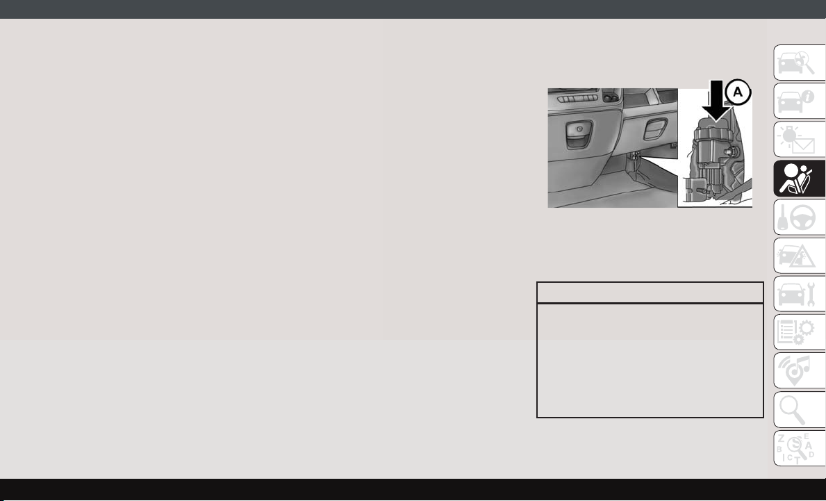
Fuel Cut Off Switch
Your vehicle is equipped with a Fuel Cut Off
switch. In the event of an accident, if the
communication network remains intact, and
the power remains intact, depending on the
nature of the event, the Fuel Cut Off Switch
may perform the following functions:
• Cut off fuel to the engine and turn off the
engine.
• Flash hazard lights as long as the battery
has power or until the hazard light button is
pressed. The hazard lights can be deactivated by pressing the hazard light button.
• Turn on the interior lights, which remain on
as long as the battery has power.
• Unlock the power door locks.
NOTE:
After an accident, remember to cycle the
ignition to the STOP (OFF/LOCK) position
and remove the key from the ignition switch
to avoid draining the battery. Carefully check
the vehicle for fuel leaks in the engine compartment and on the ground near the engine
compartment and fuel tank before resetting
the system and starting the engine. If there
are no fuel leaks or damage to the vehicle
electrical devices (e.g. headlights) after an
accident, reset the Fuel Cut Off Switch by
following the procedure described below. If
you have any doubt, contact an authorized
dealer.
Fuel Cut Off Switch Reset Procedure
In order to reset the Fuel Cut Off Switch after
an event push the “A” Button located underneath the instrument panel on the passenger
side.
Fuel Cut Off Switch
WARNING!
If, after an accident, you smell fuel or see
leaks from the fuel system, do not reset the
Fuel Cut Off Switch to avoid the risk of fire.
Before resetting the Fuel Cut Off Switch,
carefully check for fuel leaks or damage to
the vehicle electrical devices (e.g. headlights).
59
Page 62
Maintaining Your Air Bag System
WARNING!
SAFETY
• Modifications to any part of the air bag
system could cause it to fail when you
need it. You could be injured if the air
bag system is not there to protect you.
Do not modify the components or wiring,
including adding any kind of badges or
stickers to the steering wheel hub trim
cover or the upper passenger side of the
instrument panel. Do not modify the
front bumper, vehicle body structure, or
add aftermarket side steps or running
boards.
• It is dangerous to try to repair any part of
the air bag system yourself. Be sure to
tell anyone who works on your vehicle
that it has an air bag system.
• Do not attempt to modify any part of your
air bag system. The air bag may inflate
accidentally or may not function properly if modifications are made. Take your
vehicle to an authorized dealer for any
air bag system service. If your seat, including your trim cover and cushion,
WARNING!
needs to be serviced in any way (including removal or loosening/tightening of
seat attachment bolts), take the vehicle
to an authorized dealer. Only manufacturer approved seat accessories may be
used. If it is necessary to modify the air
bag system for persons with disabilities,
contact an authorized dealer.
Event Data Recorder (EDR)
This vehicle is equipped with an event data
recorder (EDR). The main purpose of an EDR
is to record, in certain crash or near crashlike situations, such as an air bag deployment
or hitting a road obstacle, data that will assist
in understanding how a vehicle’s systems
performed. The EDR is designed to record
data related to vehicle dynamics and safety
systems for a short period of time, typically
30 seconds or less. The EDR in this vehicle is
designed to record such data as:
• How various systems in your vehicle were
operating;
• Whether or not the driver and passenger
safety belts were buckled/fastened;
• How far (if at all) the driver was depressing
the accelerator and/or brake pedal; and,
• How fast the vehicle was traveling.
These data can help provide a better understanding of the circumstances in which
crashes and injuries occur.
NOTE:
EDR data are recorded by your vehicle only if
a non-trivial crash situation occurs; no data
are recorded by the EDR under normal driving
conditions and no personal data (e.g., name,
gender, age, and crash location) are recorded. However, other parties, such as law
enforcement, could combine the EDR data
with the type of personally identifying data
routinely acquired during a crash investigation.
To read data recorded by an EDR, special
equipment is required, and access to the
vehicle or the EDR is needed. In addition to
the vehicle manufacturer, other parties, such
60
Page 63
as law enforcement, that have the special
equipment, can read the information if they
have access to the vehicle or the EDR.
Child Restraints
Everyone in your vehicle needs to be buckled
up at all times, including babies and children. Every state in the United States, and
every Canadian province, requires that small
children ride in proper restraint systems. This
is the law, and you can be prosecuted for
ignoring it.
Children 12 years or younger should ride
properly buckled up in a rear seat, if available. According to crash statistics, children
are safer when properly restrained in the rear
seats rather than in the front.
In a collision, an unrestrained child can
become a projectile inside the vehicle. The
force required to hold even an infant on
your lap could become so great that you
could not hold the child, no matter how
strong you are. The child and others could
be badly injured or killed. Any child riding
in your vehicle should be in a proper restraint for the child’s size.
There are different sizes and types of restraints for children from newborn size to the
child almost large enough for an adult safety
belt. Always check the child seat Owner’s
Manual to make sure you have the correct
seat for your child. Carefully read and follow
all the instructions and warnings in the child
WARNING!
Summary Of Recommendations For Restraining Children In Vehicles
Child Size, Height, Weight Or Age Recommended Type Of Child Restraint
Infants and Toddlers
Children who are two years old or younger and
who have not reached the height or weight lim-
its of their child restraint
restraint Owner’s Manual and on all the labels
attached to the child restraint.
Before buying any restraint system, make
sure that it has a label certifying that it meets
all applicable Safety Standards. You should
also make sure that you can install it in the
vehicle where you will use it.
NOTE:
• For additional information, refer to http://
www.nhtsa.gov/parents-and-caregivers or
call: 1–888–327–4236
• Canadian residents should refer to
Transport Canada’s website for additional
information: http://www.tc.gc.ca/eng/
motorvehiclesafety/safedriverschildsafety-index-53.htm
Either an Infant Carrier or a Convertible Child
Restraint, facing rearward in a rear seat of
the vehicle
61
Page 64

SAFETY
Children Too Large for Child Restraints
Small Children
Larger Children
Child Size, Height, Weight Or Age Recommended Type Of Child Restraint
Children who are at least two years old or who
have outgrown the height or weight limit of
their rear-facing child restraint
Children who have outgrown their forward-
facing child restraint, but are too small to prop-
erly fit the vehicle’s seat belt
Children 12 years old or younger, who have
outgrown the height or weight limit of their
booster seat
Forward-Facing Child Restraint with a five-
point Harness, facing forward in a rear seat of
the vehicle
Belt Positioning Booster Seat and the vehicle
seat belt, seated in a rear seat of the vehicle
Vehicle Seat Belt, seated in a rear seat of
the vehicle
Infant And Child Restraints
Safety experts recommend that children ride
rear-facing in the vehicle until they are two
years old or until they reach either the height
or weight limit of their rear-facing child restraint. Two types of child restraints can be
used rear-facing: infant carriers and convertible child seats.
The infant carrier is only used rear-facing in
the vehicle. It is recommended for children
from birth until they reach the weight or
height limit of the infant carrier. Convertible
child seats can be used either rear-facing or
forward-facing in the vehicle. Convertible
child seats often have a higher weight limit in
62
the rear-facing direction than infant carriers
do, so they can be used rear-facing by children who have outgrown their infant carrier
but are still less than at least two years old.
Children should remain rear-facing until they
reach the highest weight or height allowed by
their convertible child seat.
WARNING!
• Never place a rear-facing child restraint
in front of an air bag. A deploying passenger front air bag can cause death or
serious injury to a child 12 years or
younger, including a child in a rearfacing child restraint.
WARNING!
• Never install a rear-facing child restraint
in the front seat of a vehicle. Only use a
rear-facing child restraint in the rear
seat. If the vehicle does not have a rear
seat, do not transport a rear-facing child
restraint in that vehicle.
Older Children And Child Restraints
Children who are two years old or who have
outgrown their rear-facing convertible child
seat can ride forward-facing in the vehicle.
Forward-facing child seats and convertible
child seats used in the forward-facing direction are for children who are over two years
Page 65
old or who have outgrown the rear-facing
weight or height limit of their rear-facing
convertible child seat. Children should remain in a forward-facing child seat with a
harness for as long as possible, up to the
highest weight or height allowed by the child
seat.
All children whose weight or height is above
the forward-facing limit for the child seat
should use a belt-positioning booster seat
until the vehicle’s seat belts fit properly. If
the child cannot sit with knees bent over the
vehicle’s seat cushion while the child’s back
is against the seatback, they should use a
belt-positioning booster seat. The child and
belt-positioning booster seat are held in the
vehicle by the seat belt.
WARNING!
• Improper installation can lead to failure
of an infant or child restraint. It could
come loose in a collision. The child
could be badly injured or killed. Follow
the child restraint manufacturer’s direc-
WARNING!
tions exactly when installing an infant or
child restraint.
• After a child restraint is installed in the
vehicle, do not move the vehicle seat
forward or rearward because it can
loosen the child restraint attachments.
Remove the child restraint before adjusting the vehicle seat position. When
the vehicle seat has been adjusted, reinstall the child restraint.
• When your child restraint is not in use,
secure it in the vehicle with the seat belt
or LATCH anchorages, or remove it from
the vehicle. Do not leave it loose in the
vehicle. In a sudden stop or accident, it
could strike the occupants or seatbacks
and cause serious personal injury.
Children Too Large For Booster Seats
Children who are large enough to wear the
shoulder belt comfortably, and whose legs are
long enough to bend over the front of the seat
when their back is against the seatback,
should use the seat belt in a rear seat. Use
this simple 5-step test to decide whether the
child can use the vehicle’s seat belt alone:
1. Can the child sit all the way back against
the back of the vehicle seat?
2. Do the child’s knees bend comfortably
over the front of the vehicle seat – while
the child is still sitting all the way back?
3. Does the shoulder belt cross the child’s
shoulder between the neck and arm?
4. Is the lap part of the belt as low as
possible, touching the child’s thighs and
not the stomach?
5. Can the child stay seated like this for the
whole trip?
If the answer to any of these questions was
“no,” then the child still needs to use a
booster seat in this vehicle. If the child is
using the lap/shoulder belt, check seat belt
fit periodically and make sure the seat belt
buckle is latched. A child’s squirming or
slouching can move the belt out of position. If
the shoulder belt contacts the face or neck,
63
Page 66

move the child closer to the center of the
vehicle, or use a booster seat to position the
seat belt on the child correctly.
SAFETY
Never allow a child to put the shoulder belt
under an arm or behind their back. In a
crash, the shoulder belt will not protect a
child properly, which may result in serious
injury or death. A child must always wear
both the lap and shoulder portions of the
seat belt correctly.
WARNING!
Installing Child Restraints In Commercial
Vehicles
This commercial vehicle is not designed for
use as a family vehicle and is not intended for
carrying children in the front passenger
seat(s). Never install rear-facing child restraints in this vehicle. Although the seat belt
can be locked to secure a child restraint,
there are no tether anchorages to complete
the proper installation of a forward-facing
child restraint. If you must carry a child in a
forward-facing child restraint, the passenger
seat should be moved to the full rearward
64
position and the child must be in a proper
restraint system based on its age, size and
weight. Follow the instructions below to secure the child restraint using the seat belt.
WARNING!
Rear-facing infant restraints must never
be secured in the passenger seat of a
vehicle with a passenger air bag. In a
collision, a passenger air bag may deploy
causing severe injury or death to infants
riding in rear-facing infant restraints.
Installing Child Restraints Using The Vehicle Seat Belt
Child restraint systems are designed to be
secured in vehicle seats by lap belts or the
lap belt portion of a lap/shoulder belt.
WARNING!
• Improper installation or failure to properly secure a child restraint can lead to
failure of the restraint. The child could
be badly injured or killed.
WARNING!
• Follow the child restraint manufacturer’s directions exactly when installing an
infant or child restraint.
The seat belts in the passenger seating positions are equipped with a Switchable Automatic Locking Retractor (ALR). This seat belt
is designed to keep the lap portion of the seat
belt tight around the child restraint so that it
is not necessary to use a locking clip. The
ALR retractor can be “switched” into a
locked mode by pulling all of the webbing out
of the retractor and then letting the webbing
retract back into the retractor. If it is locked,
the ALR will make a clicking noise while the
webbing is pulled back into the retractor.
Refer to the “Automatic Locking Mode” description in “Switchable Automatic Locking
Retractors (ALR)” under “Occupant Restraint Systems” for additional information
on ALR.
Page 67
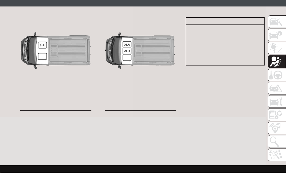
Front Bucket Seat Automatic Locking
Retractor (ALR) Location
ALR = Switchable Automatic Locking
Retractor
Front Bench Seat Automatic Locking
Retractor (ALR) Locations
ALR = Switchable Automatic Locking
Retractor
Installing A Child Restraint With A Switchable Automatic Locking Retractor (ALR)
Child restraint systems are designed to be
secured in vehicle seats by lap belts or the lap
belt portion of a lap/shoulder belt.
WARNING!
• Improper installation or failure to properly secure a child restraint can lead to
failure of the restraint. The child could
be badly injured or killed.
• Follow the child restraint manufacturer’s
directions exactly when installing an infant or child restraint.
1. Place the child seat in the center of the
seating position.
2. Pull enough of the seat belt webbing from
the retractor to pass it through the belt
path of the child restraint. Do not twist the
belt webbing in the belt path.
3. Slide the latch plate into the buckle until
you hear a “click.”
4. Pull on the webbing to make the lap
portion tight against the child seat.
5. To lock the seat belt, pull down on the
shoulder part of the belt until you have
pulled all the seat belt webbing out of the
retractor. Then, allow the webbing to retract back into the retractor. As the web-
65
Page 68
bing retracts, you will hear a clicking
sound. This means the seat belt is now in
the Automatic Locking mode.
6. Try to pull the webbing out of the retractor.
SAFETY
If it is locked, you should not be able to
pull out any webbing. If the retractor is
not locked, repeat step 5.
7. Finally, pull up on any excess webbing to
tighten the lap portion around the child
restraint while you push the child restraint
rearward and downward into the vehicle
seat.
8. Test that the child restraint is installed
tightly by pulling back and forth on the
child seat at the belt path. It should not
move more than 1 inch (25.4 mm) in any
direction.
Any seat belt system will loosen with time, so
check the belt occasionally, and pull it tight if
necessary.
Transporting Pets
Air Bags deploying in the front seat could
harm your pet. An unrestrained pet will be
thrown about and possibly injured, or injure a
passenger during panic braking or in a collision.
Pets should be restrained in the rear seat (if
equipped) in pet harnesses or pet carriers
that are secured by seat belts.
SAFETY TIPS
Transporting Passengers
NEVER TRANSPORT PASSENGERS IN THE
CARGO AREA.
WARNING!
• Do not leave children or animals inside
parked vehicles in hot weather. Interior
heat build-up may cause serious injury
or death.
• It is extremely dangerous to ride in a
cargo area, inside or outside of a vehicle.
WARNING!
In a collision, people riding in these
areas are more likely to be seriously
injured or killed.
• Do not allow people to ride in any area of
your vehicle that is not equipped with
seats and seat belts.
• Be sure everyone in your vehicle is in a
seat and using a seat belt properly.
Exhaust Gas
WARNING!
Exhaust gases can injure or kill. They contain carbon monoxide (CO), which is colorless and odorless. Breathing it can make
you unconscious and can eventually poison you. To avoid breathing (CO), follow
these safety tips:
• Do not run the engine in a closed garage
or in confined areas any longer than
needed to move your vehicle in or out of
the area.
66
Page 69
WARNING!
• If you are required to drive with the
trunk/liftgate/rear doors open, make
sure that all windows are closed and the
climate control BLOWER switch is set at
high speed. DO NOT use the recirculation mode.
• If it is necessary to sit in a parked
vehicle with the engine running, adjust
your heating or cooling controls to force
outside air into the vehicle. Set the
blower at high speed.
The best protection against carbon monoxide
entry into the vehicle body is a properly maintained engine exhaust system.
Whenever a change is noticed in the sound of
the exhaust system, when exhaust fumes can
be detected inside the vehicle, or when the
underside or rear of the vehicle is damaged,
have a competent mechanic inspect the complete exhaust system and adjacent body areas for broken, damaged, deteriorated, or
mispositioned parts. Open seams or loose
connections could permit exhaust fumes to
seep into the passenger compartment. In
addition, inspect the exhaust system each
time the vehicle is raised for lubrication or oil
change. Replace as required.
Safety Checks You Should Make
Inside The Vehicle
Seat Belts
Inspect the seat belt system periodically,
checking for cuts, frays, and loose parts. Damaged parts must be replaced immediately. Do
not disassemble or modify the system.
Front seat belt assemblies must be replaced
after a collision. Rear seat belt assemblies
must be replaced after a collision if they have
been damaged (i.e., bent retractor, torn webbing, etc.). If there is any question regarding
seat belt or retractor condition, replace the
seat belt.
Air Bag Warning Light
The Air Bag warning light will turn on for
four to eight seconds as a bulb check when
the ignition switch is first turned to ON/RUN.
If the light is either not on during starting,
stays on, or turns on while driving, have the
system inspected at an authorized dealer as
soon as possible. After the bulb check, this
light will illuminate with a single chime when
a fault with the Air Bag System has been
detected. It will stay on until the fault is
removed. If the light comes on intermittently
or remains on while driving, have an authorized dealer service the vehicle immediately.
Refer to “Occupant Restraint Systems” in
“Safety” for further information.
Defroster
Check operation by selecting the defrost
mode and place the blower control on high
speed. You should be able to feel the air
directed against the windshield. See an authorized dealer for service if your defroster is
inoperable.
Floor Mat Safety Information
Always use floor mats designed to fit your
vehicle. Only use a floor mat that does not
interfere with the operation of the accelerator, brake or clutch pedals. Only use a floor
mat that is securely attached using the floor
67
Page 70
mat fasteners so it cannot slip out of position
and interfere with the accelerator, brake or
clutch pedals or impair safe operation of your
vehicle in other ways.
SAFETY
WARNING!
An improperly attached, damaged, folded,
or stacked floor mat, or damaged floor mat
fasteners may cause your floor mat to
interfere with the accelerator, brake, or
clutch pedals and cause a loss of vehicle
control. To prevent SERIOUS INJURY or
DEATH:
• ALWAYS securely attach
mat using the floor mat fasteners. DO
NOT install your floor mat upside down
or turn your floor mat over. Lightly pull to
confirm mat is secured using the floor
mat fasteners on a regular basis.
• ALWAYS REMOVE THE EXISTING
FLOOR MAT FROM THE VEHICLE
before installing any other floor mat.
NEVER install or stack an additional
floor mat on top of an existing floor mat.
• ONLY install floor mats designed to fit
your vehicle. NEVER install a floor mat
your floor
WARNING!
that cannot be properly attached and
secured to your vehicle. If a floor mat
needs to be replaced, only use a FCA
approved floor mat for the specific
make, model, and year of your vehicle.
• ONLY use the driver’s side floor mat on
the driver’s side floor area. To check for
interference, with the vehicle properly
parked with the engine off, fully depress
the accelerator, the brake, and the
clutch pedal (if present) to check for
interference. If your floor mat interferes
with the operation of any pedal, or is not
secure to the floor, remove the floor mat
from the vehicle and place the floor mat
in your trunk.
• ONLY use the passenger’s side floor mat
on the passenger’s side floor area.
• ALWAYS make sure objects cannot fall
or slide into the driver’s side floor area
when the vehicle is moving. Objects can
become trapped under accelerator,
brake, or clutch pedals and could cause
a loss of vehicle control.
WARNING!
• NEVER place any objects under the floor
mat (e.g., towels, keys, etc.). These objects could change the position of the
floor mat and may cause interference
with the accelerator, brake, or clutch
pedals.
• If the vehicle carpet has been removed
and re-installed, always properly attach
carpet to the floor and check the floor
mat fasteners are secure to the vehicle
carpet. Fully depress each pedal to
check for interference with the accelerator, brake, or clutch pedals then reinstall the floor mats.
• It is recommended to only use mild soap
and water to clean your floor mats. After
cleaning, always check your floor mat
has been properly installed and is secured to your vehicle using the floor mat
fasteners by lightly pulling mat.
68
Page 71

Periodic Safety Checks You
Should Make Outside The Vehicle
Tires
Examine tires for excessive tread wear and
uneven wear patterns. Check for stones,
nails, glass, or other objects lodged in the
tread or sidewall. Inspect the tread for cuts
and cracks. Inspect sidewalls for cuts,
cracks, and bulges. Check the wheel bolts for
tightness. Check the tires (including spare)
for proper cold inflation pressure.
Lights
Have someone observe the operation of brake
lights and exterior lights while you work the
controls. Check turn signal and high beam
indicator lights on the instrument panel.
Door Latches
Check for proper closing, latching, and locking.
Fluid Leaks
Check area under the vehicle after overnight
parking for fuel, coolant, oil, or other fluid
leaks. Also, if gasoline fumes are detected or
if fuel, or brake fluid leaks are suspected. The
cause should be located and corrected immediately.
69
Page 72
STARTING THE ENGINE
Before starting your vehicle, adjust your seat,
adjust both inside and outside mirrors, and
fasten your seat belts.
WARNING!
• Never leave children alone in a vehicle,
or with access to an unlocked vehicle.
• Allowing children to be in a vehicle unattended is dangerous for a number of
reasons. A child or others could be seriously or fatally injured. Children should
be warned not to touch the parking
STARTING AND OPERATING
brake, brake pedal or the transmission
gear selector.
• Do not leave the key fob in or near the
vehicle (or in a location accessible to
children). A child could operate power
windows, other controls, or move the
vehicle.
Normal Starting
NOTE:
Normal starting of either a cold or a warm
engine is obtained without pumping or pressing the accelerator pedal.
Turn the ignition switch to the AVV (START)
position and release it when the engine
starts. If the engine fails to start within
10 seconds, turn the ignition switch to the
STOP (OFF/LOCK) position, wait 10 to
15 seconds, then repeat the “Normal Starting” procedure.
ENGINE BREAK-IN RECOMMENDATIONS
A long break-in period is not required for the
engine and drivetrain (transmission and axle)
in your vehicle.
Drive moderately during the first 300 miles
(500 km). After the initial 60 miles
(100 km), speeds up to 50 or 55 mph (80 or
90 km/h) are desirable.
While cruising, brief full-throttle acceleration
within the limits of local traffic laws contributes to a good break-in. Wide-open throttle
acceleration in low gear can be detrimental
and should be avoided.
The engine oil installed in the engine at the
factory is a high-quality energy conserving
type lubricant. Oil changes should be consistent with anticipated climate conditions under which vehicle operations will occur. For
the recommended viscosity and quality
grades, refer to “Fluids And Lubricants” in
“Technical Specifications”.
CAUTION!
Never use Non-Detergent Oil or Straight
Mineral Oil in the engine or damage may
result.
NOTE:
A new engine may consume some oil during
its first few thousand miles (kilometers) of
operation. This should be considered a normal part of the break-in and not interpreted
70
Page 73
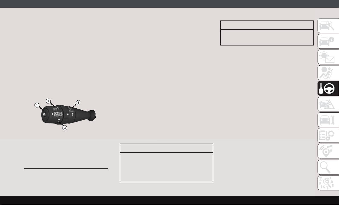
as a problem. Please check your oil level with
the engine oil indicator often during the
break in period. Add oil as required.
SPEED CONTROL — IF EQUIP PED
When engaged, the Speed Control takes over
accelerator operations at speeds greater than
25 mph (40 km/h) up to the maximum speed
of 100 mph (160 km/h).
The Speed Control Lever is located on the left
side of the steering column.
Speed Control Lever
1 — Resume
2 — Set/Accel
3 — On/Off
4 — Decel
NOTE:
In order to ensure proper operation, the
Speed Control System has been designed to
shut down if multiple Speed Control functions are operated at the same time. If this
occurs, the Speed Control System can be
reactivated by rotating the Speed Control
ON/OFF center ring and resetting the desired
vehicle set speed.
To Activate
Rotate the center ring upward on the Speed
Control lever to turn the system on. The
Cruise Indicator Light in the instrument cluster display will illuminate. To turn the system
off, rotate the center ring upward a second
time. The Cruise Indicator Light will turn off.
The system should be turned off when not in
use.
WARNING!
Leaving the Speed Control system on when
not in use is dangerous. You could accidentally set the system or cause it to go
faster than you want. You could lose con-
WARNING!
trol and have an accident. Always leave the
system off when you are not using it.
To Set A Desired Speed
Turn the Speed Control on. When the vehicle
has reached the desired speed, move the
Speed Control lever upward SET (+) and
release. Release the accelerator and the vehicle will operate at the selected speed.
NOTE:
The vehicle should be traveling at a steady
speed and on level ground before moving the
Speed Control lever upward SET (+).
To Vary The Speed Setting
To Increase Speed
When the Speed Control is set, you can increase speed by tapping the Speed Control
lever up SET (+).
The driver's preferred units can be selected
through the radio settings if equipped. Refer
to ”Uconnect Settings” in “Multimedia” in
71
Page 74

your Owner’s Manual for more information.
The speed increment shown is dependant on
the chosen speed unit of U.S. (mph) or Metric (km/h):
U.S. Speed (mph)
• Tapping the Speed Control lever up SET (+)
once will result in a 1 mph increase in set
speed. Each subsequent tap of the lever
results in an increase of 1 mph.
• If the lever is continually held up, the set
speed will continue to increase until the
lever is released, then the new set speed
will be established.
STARTING AND OPERATING
Metric Speed (km/h)
• Tapping the Speed Control lever up SET (+)
once will result in a 1 km/h increase in set
speed. Each subsequent tap of the lever
results in an increase of 1 km/h.
• If the lever is continually held up, the set
speed will continue to increase until the
lever is released, then the new set speed
will be established.
72
To Decrease Speed
When the Speed Control is set, you can decrease speed by tapping the Speed Control
lever down (-).
The driver's preferred units can be selected
through the radio settings if equipped. Refer
to ”Uconnect Settings” in “Multimedia” in
your Owner’s Manual for more information.
The speed increment shown is dependant on
the chosen speed unit of U.S. (mph) or Metric (km/h):
U.S. Speed (mph)
• Tapping the Speed Control lever down (-)
once will result in a 1 mph decrease in set
speed. Each subsequent tap of the lever
results in a decrease of 1 mph.
• If the lever is continually held down, the set
speed will continue to decrease until the
lever is released, then the new set speed
will be established.
Metric Speed (km/h)
• Tapping the Speed Control lever down (-)
once will result in a 1 km/h decrease in set
speed. Each subsequent tap of the lever
results in a decrease of 1 km/h.
• If the lever is continually held down, the set
speed will continue to decrease until the
lever is released, then the new set speed
will be established.
To Accelerate For Passing
Press the accelerator as you would normally.
When the pedal is released, the vehicle will
return to the set speed.
Using Speed Control On Hills
The transmission may downshift on hills to
maintain the vehicle set speed.
NOTE:
The Speed Control system maintains speed
up and down hills. A slight speed change on
moderate hills is normal.
On steep hills, a greater speed loss or gain
may occur so it may be preferable to drive
without Speed Control.
WARNING!
Speed Control can be dangerous where the
system cannot maintain a constant speed.
Page 75
WARNING!
Your vehicle could go too fast for the conditions, and you could lose control and
have an accident. Do not use Speed Control in heavy traffic or on roads that are
winding, icy, snow-covered or slippery.
To Resume Speed
To resume a previously set speed, push the
RES button and release. Resume can be used
at any speed above 20 mph (32 km/h) up to
the maximum speed of 100 mph (160 km/h).
To Deactivate
A soft tap on the brake pedal, pushing the
RES button, or normal brake pressure while
slowing the vehicle will deactivate Speed
Control without erasing the set speed
memory. Rotating the center ring upward to
turn the system off or turning the ignition
switch OFF erases the set speed memory.
PARKSENSE REAR PARK ASSIST — IF EQUIPPED
If an obstacle is behind the vehicle when
REVERSE gear is engaged, an audible alert is
activated.
The tones emitted by the loudspeaker inform
the driver that the vehicle is approaching an
obstacle. The pauses between the tones are
directly proportional to the distance from the
obstacle. Pulses emitted in quick succession
indicate the presence of a very close obstacle. A continuous tone indicates that the
obstacle is less than 12 inches (30 cm) away.
PARKVIEW REAR BACK-UP CAMERA
You can see an on-screen image of the rear of
your vehicle whenever the gear selector is put
into REVERSE. The ParkView Rear Back-Up
Camera image is displayed on the touchscreen display located on the center stack of
the instrument panel.
NOTE:
If the touchscreen display appears foggy,
clean the camera lens located on the top rear
of the vehicle below the center light.
WARNING!
Drivers must be careful when backing up
even when using the Rear Back-Up Camera. Always check carefully behind your
vehicle, and be sure to check for pedestrians, animals, other vehicles, obstructions,
or blind spots before backing up. You are
responsible for the safety of your surroundings and must continue to pay attention
while backing up. Failure to do so can
result in serious injury or death.
73
Page 76
REFUELING THE VEHICLE
The gas cap is located behind the fuel filler
door on the left side of the vehicle. If the gas
cap is lost or damaged, be sure the replacement cap is for use with this vehicle.
WARNING!
• Never have any smoking materials lit in
or near the vehicle when the fuel door is
open or the tank is being filled.
• Never add fuel when the engine is running. This is in violation of most state
and federal fire regulations and may
STARTING AND OPERATING
cause the “Malfunction Indicator Light”
to turn on.
• A fire may result if fuel is pumped into a
portable container that is inside of a
vehicle. You could be burned. Always
place fuel containers on the ground
while filling.
CAUTION!
• Damage to the fuel system or emissions
control system could result from using
an improper fuel tank filler tube cap.
• A poorly fitting fuel filler cap could let
impurities into the fuel system.
• A poorly fitting fuel filler cap may cause
the “Malfunction Indicator Light (MIL)”
to turn on.
• To avoid fuel spillage and overfilling, do
not “top off” the fuel tank after filling.
When the fuel nozzle “clicks” or shuts
off, the fuel tank is full.
NOTE:
• When the fuel nozzle “clicks” or shuts off,
the fuel tank is full.
• Tighten the fuel filler cap until you hear a
“clicking” sound. This is an indication that
the fuel filler cap is properly tightened.
• If the gas cap is not tightened properly, the
MIL may come on. Be sure the gas cap is
tightened every time the vehicle is
refueled.
Materials Added To Fuel
Designated TOP TIER
Detergent Gasoline
contains a higher level
of detergents to further aide in minimizing engine and fuel
system deposits. When
available, the usage of
TOP TIER Detergent gasoline is recommended. Visit www.toptiergas.com for a list
of TOP TIER Detergent Gasoline Retailers.
Indiscriminate use of fuel system cleaning
agents should be avoided. Many of these
materials intended for gum and varnish removal may contain active solvents or similar
ingredients. These can harm fuel system gasket and diaphragm materials.
74
Page 77
TRAILER TOWING
Trailer Towing Weights (Maximum
Trailer Weight Ratings)
NOTE:
For trailer towing information (maximum
trailer weight ratings) refer to the following
website addresses:
• ramtrucks.com/en/towing_guide/
• ramtruck.ca (Canada)
• rambodybuilder.com
RECREATIONAL TOWING (BEHIND MOTORHOME, ETC.)
Towing This Vehicle Behind Another Vehicle
Towing Condition Wheels OFF the Ground Automatic Transmission
Flat Tow NONE
Dolly Tow
On Trailer ALL OK
NOTE:
When towing your vehicle, always follow applicable state and provincial laws. Contact state and provincial Highway Safety offices for additional details.
Front OK
Rear
NOT ALLOWED
NOT ALLOWED
75
Page 78

Recreational Towing
Recreational towing is allowed ONLY if the
front wheels are OFF the ground. This may be
accomplished using a tow dolly or vehicle
trailer. If using a tow dolly, follow this procedure:
1. Properly secure the dolly to the tow vehicle, following the dolly manufacturer's
instructions.
2. Drive the front wheels onto the tow dolly.
STARTING AND OPERATING
3. Firmly apply the parking brake. Place the
transmission in PARK.
4. Properly secure the front wheels to the
dolly, following the dolly manufacturer's
instructions.
5. Release the parking brake.
CAUTION!
• DO NOT flat tow this vehicle. Damage to
the drivetrain will result. If this vehicle
CAUTION!
requires towing, make sure the drive
wheels are OFF the ground.
• Towing this vehicle in violation of the
above requirements can cause severe
transmission damage. Damage from improper towing is not covered under the
New Vehicle Limited Warranty.
76
Page 79
BULB REPLACEMENT
Replacement Bulbs
Interior Bulbs
Bulb Number
Dome Lamp C5W
Courtesy Lamp FF500
Cargo Lamp C5W
Exterior Bulbs
Bulb Number
Front Low and High Beam Headlamp H7SLL
Front Park/Turn Signal Lamps 7444NA
Daytime Running Lamps (If Equipped) 7440
Front Side Marker Lamps W3W
Rear Tail/Stop Lamps 7443
Rear Turn Signal Lamps 7440NA
Rear Backup Lamps 921
Rear Side Marker Lamps W3W
77
Page 80
Bulb Number
Front Fog Lamps H11
License Plate Lamps C5W
Front Roof Lamps WY5W
Rear Roof Lamps W3W
NOTE:
•
Numbers refer to commercial bulb types that can be purchased from your authorized dealer.
• If a bulb needs to be replaced, visit your authorized dealer.
FUSES
IN CASE OF EMERGENCY
• When replacing a blown fuse, always use
an appropriate replacement fuse with
the same amp rating as the original fuse.
Never replace a fuse with another fuse of
higher amp rating. Never replace a
blown fuse with metal wires or any other
material. Do not place a fuse inside a
circuit breaker cavity or vice versa. Failure to use proper fuses may result in
78
WARNING!
WARNING!
serious personal injury, fire and/or property damage.
• Before replacing a fuse, make sure that
the ignition is off and that all the other
services are switched off and/or disengaged.
• If the replaced fuse blows again, contact
an authorized dealer.
• If a general protection fuse for safety
systems (air bag system, braking system), power unit systems (engine system, transmission system) or steering
WARNING!
system blows, contact an authorized
dealer.
Underhood Fuses
The Front Power Distribution Center is located on the driver’s side of the engine compartment. To access the fuses, remove the
cover.
The ID number of the electrical component
corresponding to each fuse can be found on
the back of the cover.
Page 81
Cavity Maxi Fuse Mini Fuse Description
F01 40 Amp Orange – Electronic Stability Control (ESC) Pump
F02
F04
F06
F07
20 Amp Yellow (3.6 Gasoline
Engine)
50 Amp Red (3.6 Gasoline
Engine)
40 Amp Orange (non A/C)
60 Amp Blue (A/C)
50 Amp Red (non A/C)
60 Amp Blue (A/C)
– Starter Relay 3.6L (3.6 Gasoline Engine)
Secondary Power Distribution Center (PDC) (Trans
–
Power Relay, Vacuum Pump, KL30 for the Shifter
Transmission Module [STM]) (3.6 Gasoline Engine)
– Engine Cooling Fan - 2nd Speed
– Engine Cooling Fan - 1st Speed
F08 40 Amp Orange – Passenger Compartment Blower
F09 – 15 Amp Blue Rear Power Outlet
F10 – 15 Amp Blue Horn
F14 – 20 Amp Yellow Power Outlet
F15 – 7.5 Amp Brown USB Charger
F16 – 7.5 Amp Brown
F17 – 20 Amp Yellow
F18 – 7.5 Amp Brown
KL15 Shifter Transmission Module (STM) (3.6),
KL15 Starter Relay Coil (3.6 Gasoline Engine)
Engine Control Module (ECM), Injectors (3.6 Gasoline
Engine)
KL30 Engine Control Module (ECM), KL30 Main Re-
lay Coil (3.6 Gasoline Engine)
F19 – 7.5 Amp Brown A/C Compressor — If Equipped
F20 – 30 Amp Green Windshield Wiper
F21 – 15 Amp Blue Fuel Pump
79
Page 82
Cavity Maxi Fuse Mini Fuse Description
F22 – 20 Amp Yellow
F23 – 20 Amp Yellow Electronic Stability Control (ESC) Valves
F24 – 7.5 Amp Brown
F30 – 15 Amp Blue Heated Mirrors
Front PDC Additional Fuses
The additional fuse box is located inside the
front PDC Box.
IN CASE OF EMERGENCY
Cavity Mini Fuse Description
F61 20 Amp Yellow Vacuum Pump (3.6 Gasoline Engine)
F62 30 Amp Green Transmission Power RELE (3.6 Gasoline Engine)
F66 5 Amp Beige Shifter Transmission Module (STM) (3.6 Gasoline Engine)
Engine Control Module (ECM), Ignition Coils
(3.6 Gasoline Engine)
KL15 Vacuum Pump Relay Coil (3.6 Gasoline Engine)
— If Equipped
80
Page 83
Interior Fuses
The interior fuse panel is part of the Body
Control Module (BCM) and is located on the
driver's side under the instrument panel.
Cavity Mini Fuse Description
F31 5 Amp Beige INT/A
F34 7.5 Amp Brown Clearance Lights
F36 15 Amp Blue +30 (ACM – TPCU – RRM – DLC)
F37 5 Amp Beige INT (BRAKE NO – IPC)
F38 15 Amp Blue Central Locking
F42 5 Amp Beige INT (BSM – SAS – BRAKE NC)
F43 20 Amp Yellow Bi-Directional Washer Pump
F47 20 Amp Yellow Driver Power Window
F48 20 Amp Yellow Passenger Power Window
F49 5 Amp Beige INT (PAM – CCS – RRM – ECM)
F50 7.5 Amp Brown INT (ORC)
F51 5 Amp Beige INT (REAR CAMERA-AUX)
F53 5 Amp Beige +30 (IPC) + FTM
F92 7.5 Amp Brown Left Fog Lamp
F93 7.5 Amp Brown Right Fog Lamp
81
Page 84
Right Central Pillar Fuses
The right central pillar fuse panel is located
on the interior side at the base of the passenger side B pillar.
Cavity Mini Fuse Description
F81 7.5 Amp Brown Seat Heater
F83 20 Amp Yellow Rear Left Windows Heater
F84 20 Amp Yellow Rear Right Windows Heater
F86 20 Amp Yellow Auxiliary Switch (From Battery) — If Equipped
F87 20 Amp Yellow Auxiliary Switch (From Ignition) — If Equipped
IN CASE OF EMERGENCY
JACKING AND TIRE CHANGING
WARNING!
• Do not attempt to change a tire on the
side of the vehicle close to moving traffic. Pull far enough off the road to avoid
the danger of being hit when operating
the jack or changing the wheel.
• Being under a jacked-up vehicle is dangerous. The vehicle could slip off the
jack and fall on you. You could be
crushed. Never put any part of your body
82
WARNING!
under a vehicle that is on a jack. If you
need to get under a raised vehicle, take
it to a service center where it can be
raised on a lift.
• Never start or run the engine while the
vehicle is on a jack.
• The jack is designed to be used as a tool
for changing tires only. The jack should
not be used to lift the vehicle for service
purposes. The vehicle should be jacked
on a firm level surface only. Avoid ice or
slippery areas.
Jack Location
The jack and jack tools are stored under the
front passenger seat.
Page 85
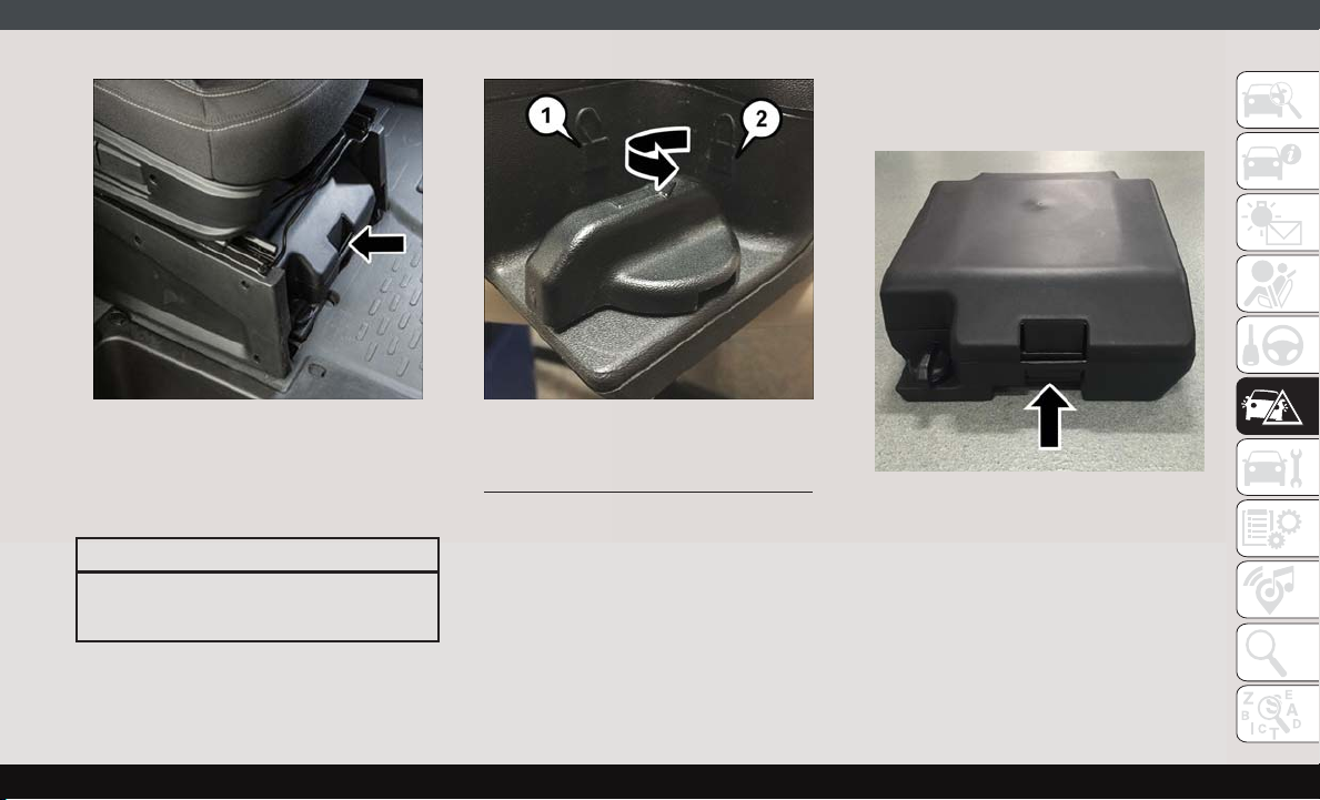
Jack Kit Location Lock Knob
To release the jack kit for it’s storage location,
turn the lock knob 1/4 turn counter clockwise
to the unlock position.
CAUTION!
Do not force lock knob over limit. Damage
to lock knob may occur.
1 — Unlock Position
2 — Lock Position
To open the jack kit container, you must push
the container’s release to separate the top
and bottom.
Container Release
83
Page 86
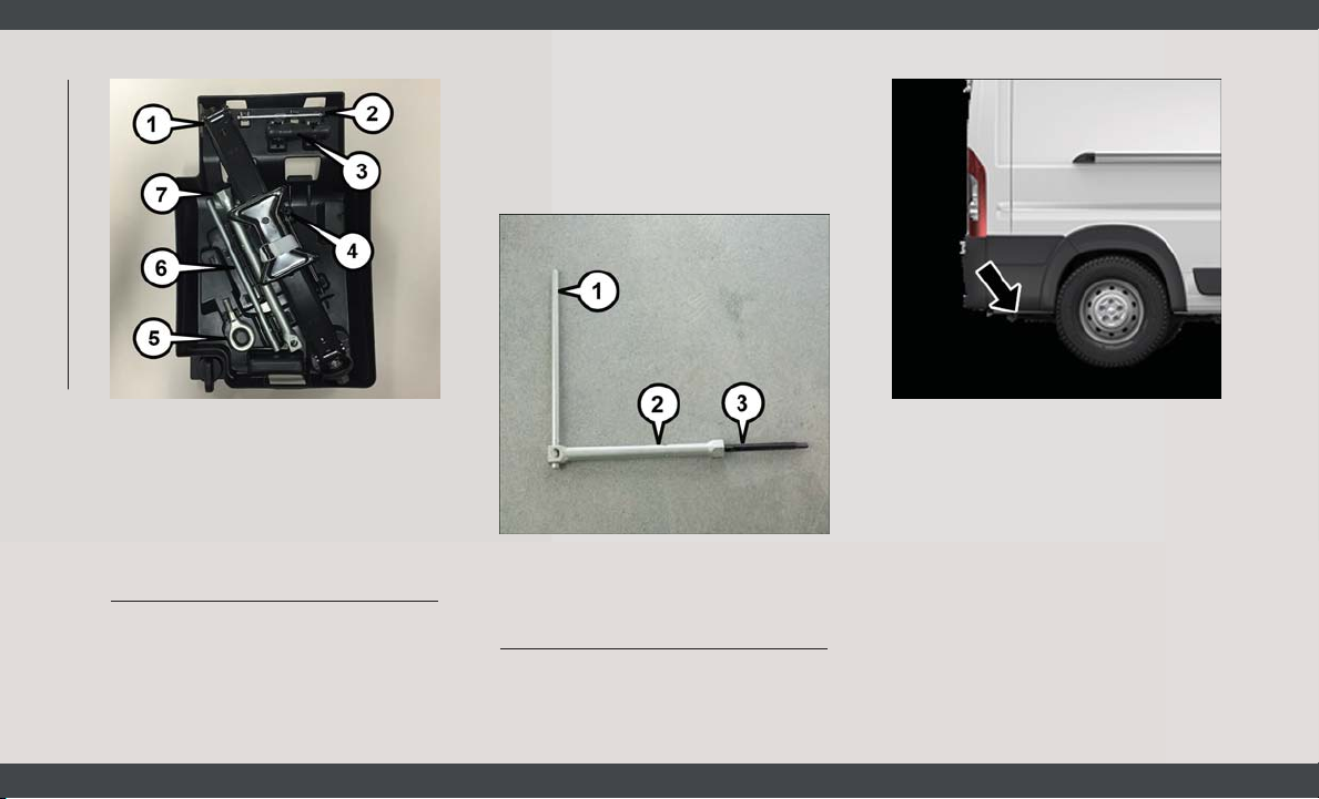
IN CASE OF EMERGENCY
1 — Jack
2 — Reversible Tool
3 — Tool Handle
4 — Winch Extension
5 — Tow Eye
6 — Wrench Handle
7 — Lug Bolt Adaptor
Jacking Tools
Spare Tire Removal
1. Remove the spare tire before attempting
to jack up the vehicle. Attach the lug bolt
adapter to the winch extension and insert
it into the winch mechanism.
Winch Location
The winch mechanism is located under
the rear of the vehicle to the right of the
spare tire.
Jack Tools
1 — Wrench Handle
2 — Lug Bolt Adapter
3 — Winch Extension
84
Page 87
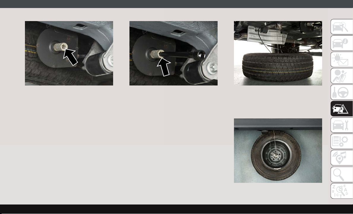
Winch Location Winch Extension Lowering Spare Tire
2. Rotate the wheel wrench handle counterclockwise until the spare tire is on the
ground with enough cable slack to allow
you to pull it out from under the vehicle.
NOTE:
The winch mechanism is designed for use
with the winch extension tube only. Use of
an air wrench or other power tools is not
recommended and can damage the
winch.
3. Pull the spare tire out from under the
vehicle to gain access to the spare tire
retainer.
Spare Tire
85
Page 88
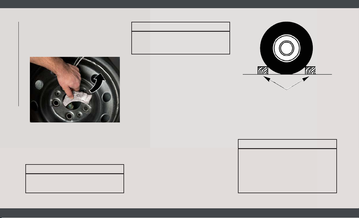
4. Lift the spare tire with one hand to give
clearance to tilt the retainer at the end of
the cable.
5. Pull the retainer through the center of the
wheel.
IN CASE OF EMERGENCY
Retainer
Preparations For Jacking
1. Park the vehicle on a firm, level surface.
Avoid ice or slippery areas.
WARNING!
Do not attempt to change a tire on the side
of the vehicle close to moving traffic. Pull
WARNING!
far enough off the road to avoid being hit
when operating the jack or changing the
wheel.
2. Turn on the Hazard Warning flasher.
3. Apply the parking brake firmly.
4. Place the transmission in PARK (REVERSE for manual transmission) .
5. Turn the ignition OFF.
6. Block both the front and rear of the wheel
diagonally opposite the jacking position.
For example, if the right front wheel is
being changed, block the left rear wheel.
Wheel Blocked
NOTE:
Passengers should not remain in the vehicle
when the vehicle is being jacked.
Jacking Instructions
WARNING!
Carefully follow these tire changing warnings to help prevent personal injury or
damage to your vehicle:
• Always park on a firm, level surface as
far from the edge of the roadway as
possible before raising the vehicle.
86
Page 89
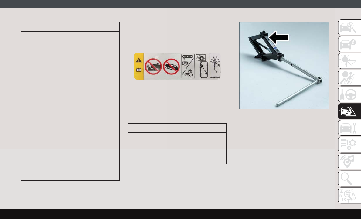
WARNING!
• Turn on the Hazard Warning flashers.
• Block the wheel diagonally opposite the
wheel to be raised.
• Apply the parking brake firmly and place
an automatic transmission in PARK; a
manual transmission in REVERSE.
• Never start or run the engine with the
vehicle on a jack.
• Do not let anyone sit in the vehicle when
it is on a jack.
• Do not get under the vehicle when it is
on a jack. If you need to get under a
raised vehicle, take it to a service center
where it can be raised on a lift.
• Only use the jack in the positions indicated and for lifting this vehicle during a
tire change.
• If working on or near a roadway, be
extremely careful of motor traffic.
• To assure that spare tires, flat or inflated, are securely stowed, spares must
be stowed with the valve stem facing the
ground.
Jack Warning Label
CAUTION!
Do not attempt to raise the vehicle by
jacking on locations other than those indicated in the Jacking Instructions for this
vehicle.
Assembled Jack
1. Loosen (but do not remove) the wheel lug
bolts by turning them to the left one turn
while the wheel is still on the ground.
87
Page 90
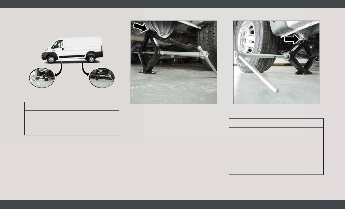
2. There are two jack engagement locations
on each side of the vehicle body.
Jacking Engagement Locations
IN CASE OF EMERGENCY
CAUTION!
Do not attempt to raise the vehicle by
jacking on locations other than those indicated.
NOTE:
The rear jacking location is located in
front of the rear tire and in front of the leaf
spring mount.
Rear Jacking Location Front Jacking Location
NOTE:
The front jacking location is located behind the front tire and in front of the
driver/passenger door.
WARNING!
Being under a jacked-up vehicle is dangerous. The vehicle could slip off the jack and
fall on you. You could be crushed. Never
get any part of your body under a vehicle
that is on a jack. If you need to get under a
raised vehicle, take it to a service center
where it can be raised on a lift.
88
Page 91
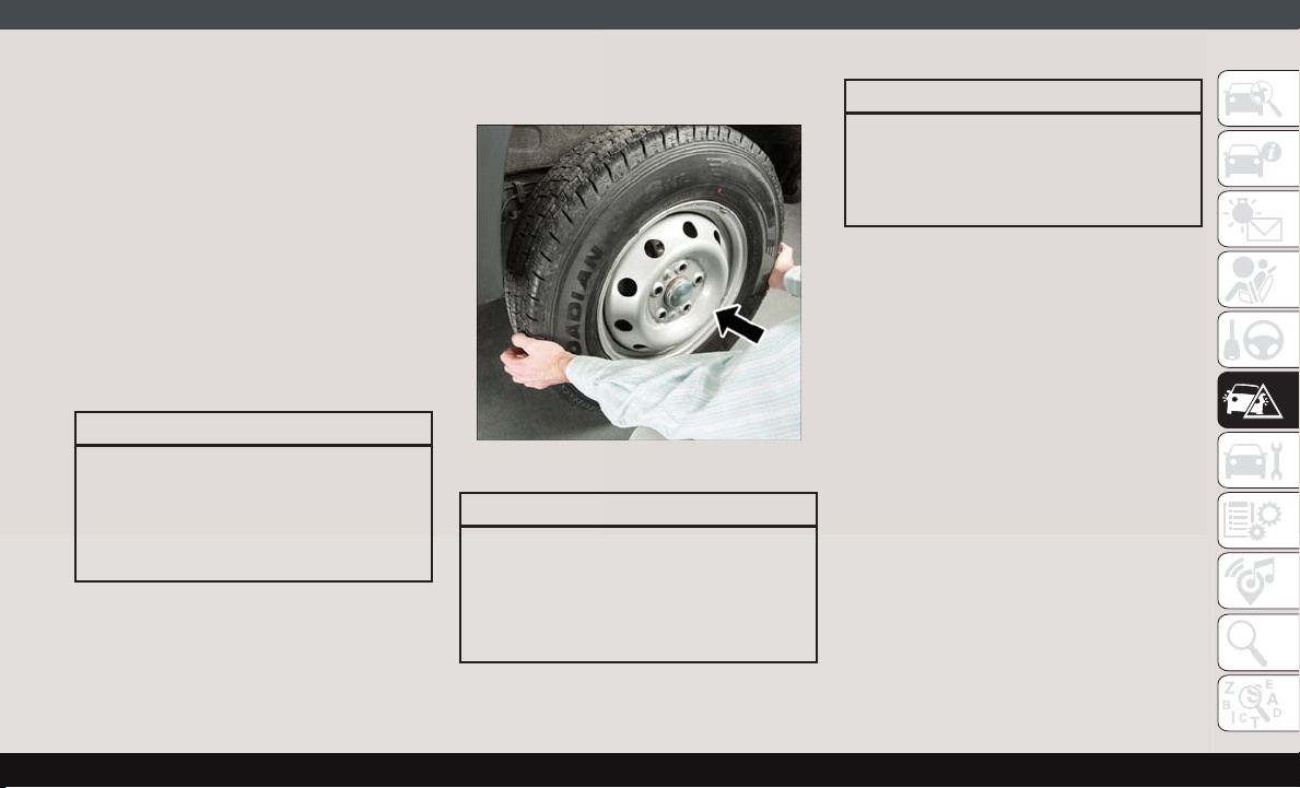
3. Place the wrench handle and lug bolt
adapter on the jack screw and turn to the
right until the jack head is properly engaged in the described location. Do not
raise the vehicle until you are sure the jack
is securely engaged.
4. Raise the vehicle by turning the jack
screw to the right, using the wrench
handle and lug bolt adapter. Raise the
vehicle only until the tire just clears the
surface and enough clearance is obtained
to install the spare tire. Minimum tire lift
provides maximum stability.
WARNING!
Raising the vehicle higher than necessary
can make the vehicle less stable. It could
slip off the jack and hurt someone near it.
Raise the vehicle only enough to remove
the tire.
5. Remove the wheel lug bolts. For vehicles
with wheel covers, remove the cover from
the wheel by hand. Do not pry the wheel
cover off. Then pull the wheel off the hub.
6. Install the spare tire. Lightly tighten the
wheel lug bolts.
Mounting Spare Tire
WARNING!
To avoid the risk of forcing the vehicle off
the jack, do not tighten the wheel nuts
fully until the vehicle has been lowered.
Failure to follow this warning may result in
serious injury.
CAUTION!
Be sure to mount the spare tire with the
valve stem facing outward. The vehicle
could be damaged if the spare tire is
mounted incorrectly.
NOTE:
Do not install the wheel cover on the spare
tire.
7. Lower the vehicle by turning the jack
screw to the left.
8. Refer to “Wheel And Tire Torque Specifications” in “Technical Specifications” for
proper wheel lug bolt torque.
9. Lower the jack to its fully-closed position.
10. Stow the damaged wheel/spare tire with
the cable and wheel spacer before driving the vehicle.
11. Install the winch extension and rotate the
wrench handle clockwise until the winch
mechanism operator hears “3 clicks” from
the device to indicate the wheel is properly
stowed under the vehicle.
89
Page 92
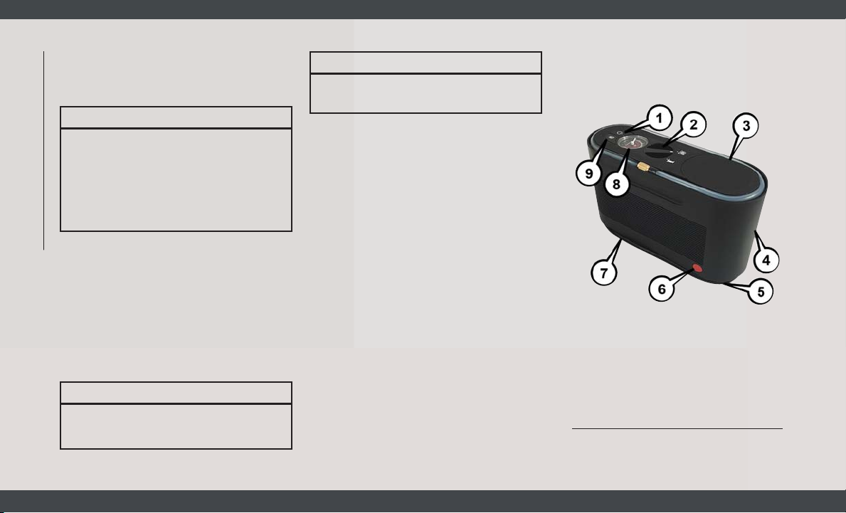
12. Stow the jack, jack handle and winch
handle tools back in the storage
compartment.
WARNING!
A loose tire or jack thrown forward in a
collision or hard stop could endanger the
occupants of the vehicle. Always stow the
jack parts and the spare tire in the places
provided. Have the deflated (flat) tire repaired or replaced immediately.
13. Check the spare tire pressure as soon as
IN CASE OF EMERGENCY
possible. Correct the tire pressure, as
required.
For vehicles with aluminum wheels:
The center cap must be pushed out from the
rear to install the retainer and stow the tire.
Wheel Covers
CAUTION!
Use a back-and-forth motion to remove the
hub cap. Do not use a twisting motion
CAUTION!
when removing the hub cap, damage to
the hub cap finish may occur.
The wheel covers on the vehicle are held in
place by the wheel lug bolts and can be removed
after the wheel lug bolts are taken off.
TIRE SERVICE KIT — IF EQUIPPED
Small punctures up to 1/4 inch (6 mm) in the
tire tread can be sealed with Tire Service Kit.
Foreign objects (e.g., screws or nails) should
not be removed from the tire. Tire Service Kit
can be used in outside temperatures down to
approximately -4°F (-20°C).
This kit will provide a temporary tire seal,
allowing you to drive your vehicle up to
100 miles (160 km) with a maximum speed
of 50 mph (80 km/h).
Tire Service Kit Storage
The Tire Service Kit is located under the
passenger seat.
Tire Service Kit Components And
Operation
Tire Service Kit Components
1 — Power
Button
2 — Mode Select Knob
3 — Sealant
Hose (Clear)
4 — Sealant
Bottle
5—Air
Pump Hose
(Black)
6 — Sealant
Bottle Release Button
7 — Power
Plug
8 — Pressure
Gauge
9 — Deflation
Button
90
Page 93
Using The Mode Select Knob And Hoses
Your Tire Service Kit is equipped with the
following symbols to indicate the air or sealant mode.
Selecting Air Mode
Turn the Mode Select Knob (2) to this position for air pump operation only. Use the
Black Air Pump Hose (5) when selecting this
mode.
Selecting Sealant Mode
Turn the Mode Select Knob (2) to this position to inject the Tire Service Kit Sealant and
to inflate the tire. Use the Sealant Hose (clear
hose) (3) when selecting this mode.
Using The Power Button
Push and release the Power Button (1) once
to turn on the Tire Service Kit. Push and
release the Power Button (1) again to turn Off
the Tire Service Kit.
Using The Deflation Button
Push the Deflation Button (9) to reduce the
air pressure in the tire if it becomes overinflated.
Tire Service Kit Usage
Precautions
• Replace the Tire Service Kit Sealant Bottle
(4) and Sealant Hose (3) prior to the expiration date (printed at the upper right hand
corner on the bottle label) to assure optimum operation of the system. Refer to
“Sealing A Tire With Tire Service Kit” section (F) “Sealant Bottle And Hose Replacement”.
• The Sealant Bottle (4) and Sealant Hose (3)
are a one tire application use and need to
be replaced after each use. Always replace
these components immediately at your
original equipment vehicle dealer.
• When the Tire Service Kit sealant is in a
liquid form, clean water and a damp cloth
will remove the material from the vehicle or
tire and wheel components. Once the sealant dries, it can easily be peeled off and
properly discarded.
• For optimum performance, make sure the
valve stem on the wheel is free of debris
before connecting the Tire Service Kit.
• You can use the Tire Service Kit air pump to
inflate bicycle tires. The kit also comes with
two needles, located in the Accessory Storage Compartment (on the bottom of the air
pump) for inflating sport balls, rafts, or
similar inflatable items. However, use only
the Air Pump Hose (5) and make sure the
Mode Select Knob (2) is in the Air Mode
when inflating such items to avoid injecting
sealant into them. The Tire Service Kit
Sealant is only intended to seal punctures
less than 1/4 inch (6 mm) diameter in the
tread of your tire.
• Do not lift or carry the Tire Service Kit by the
hoses.
WARNING!
Do not attempt to seal a tire on the side of
•
the vehicle closest to traffic. Pull far
enough off the road to avoid the danger of
being hit when using the Tire Service Kit.
• Do not use Tire Service Kit or drive the
vehicle under the following circumstances:
– If the puncture in the tire tread is
approximately 1/4 inch (6 mm) or
larger.
91
Page 94
WARNING!
– If the tire has any sidewall damage.
– If the tire has any damage from
driving with extremely low tire pressure.
– If the tire has any damage from
driving on a flat tire.
– If the wheel has any damage.
– If you are unsure of the condition of
the tire or the wheel.
• Keep Tire Service Kit away from open
flames or heat source.
• A loose Tire Service Kit thrown forward in
IN CASE OF EMERGENCY
a collision or hard stop could endanger
the occupants of the vehicle. Always
stow the Tire Service Kit in the place
provided. Failure to follow these warnings can result in injuries that are serious or fatal to you, your passengers, and
others around you.
• Take care not to allow the contents of
Tire Service Kit to come in contact with
hair, eyes, or clothing. Tire Service Kit
sealant is harmful if inhaled, swallowed,
or absorbed through the skin. It causes
skin, eye, and respiratory irritation.
92
WARNING!
Flush immediately with plenty of water if
there is any contact with eyes or skin.
Change clothing as soon as possible, if
there is any contact with clothing.
• Tire Service Kit Sealant solution contains latex. In case of an allergic reaction
or rash, consult a physician immediately. Keep Tire Service Kit out of reach
of children. If swallowed, rinse mouth
immediately with plenty of water and
drink plenty of water. Do not induce
vomiting! Consult a physician immediately.
Sealing A Tire With Tire Service
Kit
(A) Whenever You Stop To Use Tire Service
Kit:
1. Pull over to a safe location and turn on the
vehicle’s Hazard Warning flashers.
2. Verify that the valve stem (on the wheel
with the deflated tire) is in a position that
is near to the ground. This will allow the
Tire Service Kit Hoses (3) and (5) to reach
the valve stem and keep the Tire Service
Kit flat on the ground. This will provide
the best positioning of the kit when injecting the sealant into the deflated tire and
running the air pump. Move the vehicle as
necessary to place the valve stem in this
position before proceeding.
3. Place the transmission in PARK (auto
transmission) or in Gear (manual transmission) and place the ignition in the OFF
position.
4. Apply the parking brake.
(B) Setting Up To Use Tire Service Kit:
1. Push in the Mode Select Knob (2) and
turn to the Sealant Mode position.
2. Uncoil the Sealant Hose (3) and then
remove the cap from the fitting at the end
of the hose.
3. Place the Tire Service Kit flat on the
ground next to the deflated tire.
4. Remove the cap from the valve stem and
then screw the fitting at the end of the
Sealant Hose (3) onto the valve stem.
Page 95

5. Uncoil the Power Plug (7) and insert the
plug into the vehicle’s 12 Volt power
outlet.
NOTE:
Do not remove foreign objects (e.g., screws or
nails) from the tire.
(C) Injecting Tire Service Kit Sealant Into
The Deflated Tire:
• Always start the engine before turning ON
the Tire Service Kit.
NOTE:
Manual transmission vehicles must have the
parking brake engaged and the gear selector
in NEUTRAL.
• After pushing the Power Button (1), the
sealant (white fluid) will flow from the Sealant Bottle (4) through the Sealant Hose (3)
and into the tire.
NOTE:
Sealant may leak out through the puncture in
the tire.
If the sealant (white fluid) does not flow within 0
– 10 seconds through the Sealant Hose (3):
1. Push the Power Button (1) to turn Off the
Tire Service Kit. Disconnect the Sealant
Hose (3) from the valve stem. Make sure
the valve stem is free of debris. Reconnect
the Sealant Hose (3) to the valve stem.
Check that the Mode Select Knob (2) is in
the Sealant Mode position and not Air
Mode. Push the Power Button (1) to turn
On the Tire Service Kit.
2. Connect the Power Plug (7) to a different
12 Volt power outlet in your vehicle or
another vehicle, if available. Make sure
the engine is running before turning ON
the Tire Service Kit.
3. The Sealant Bottle (4) may be empty due
to previous use. Call for assistance.
NOTE:
If the Mode Select Knob (2) is on Air Mode
and the pump is operating, air will dispense
from the Air Pump Hose (5) only, not the
Sealant Hose (3).
If the sealant (white fluid) does flow through the
Sealant Hose (3):
1. Continue to operate the pump until sealant is no longer flowing through the hose
(typically takes 30 - 70 seconds). As the
sealant flows through the Sealant Hose
(3), the Pressure Gauge (8) can read as
high as 70 psi (4.8 Bar). The Pressure
Gauge (8) will decrease quickly from approximately 70 psi (4.8 Bar) to the actual
tire pressure when the Sealant Bottle (4)
is empty.
2. The pump will start to inject air into the
tire immediately after the Sealant Bottle
(4) is empty. Continue to operate the
pump and inflate the tire to the pressure
indicated on the tire pressure label on the
driver-side latch pillar (recommended
pressure). Check the tire pressure by looking at the Pressure Gauge (8).
If the tire does not inflate to at least 26 psi
(1.8 Bar) pressure within 15 minutes:
• The tire is too badly damaged. Do not at-
tempt to drive the vehicle further. Call for
assistance.
93
Page 96

NOTE:
If the tire becomes overinflated, push the
Deflation Button to reduce the tire pressure
to the recommended inflation pressure before continuing.
If the tire inflates to the recommended pressure
or is at least 26 psi (1.8 Bar) pressure within
15 minutes:
1. Push the Power Button (1) to turn off the
Tire Service Kit.
2. Remove the Speed Limit sticker from the
top of the Sealant Bottle (4) and place the
IN CASE OF EMERGENCY
sticker on the instrument panel.
3. Immediately disconnect the Sealant Hose
(3) from the valve stem, reinstall the cap
on the fitting at the end of the hose, and
place the Tire Service Kit in the vehicle
storage location. Quickly proceed to (D)
“Drive Vehicle.”
CAUTION!
• The metal end fitting from Power Plug
(8) may get hot after use, so it should be
handled carefully.
CAUTION!
• Failure to reinstall the cap on the fitting
at the end of the Sealant Hose (6) can
result in sealant contacting your skin,
clothing, and the vehicle’s interior. It
can also result in sealant contacting
internal Tire Service Kit components
which may cause permanent damage to
the kit.
(D) Drive Vehicle:
Immediately after injecting sealant and inflating the tire, drive the vehicle 5 miles
(8 km) or ten minutes to ensure distribution
of the Tire Service Kit Sealant within the tire.
Do not exceed 50 mph (80 km/h).
WARNING!
Tire Service Kit is not a permanent flat tire
repair. Have the tire inspected and repaired or replaced after using Tire Service
Kit. Do not exceed 50 mph (80 km/h) until
the tire is repaired or replaced. Failure to
follow this warning can result in injuries
WARNING!
that are serious or fatal to you, your passengers, and others around you.
(E) After Driving:
Pull over to a safe location. Refer to “(A)
Whenever You Stop To Use Tire Service Kit”
before continuing.
1. Push in the Mode Select Knob (2) and
turn to the Air Mode position.
2. Uncoil the power plug and insert the plug
into the vehicle's 12 Volt power outlet.
3. Uncoil the Air Pump Hose (5) (black in
color) and screw the fitting at the end of
hose onto the valve stem.
4. Check the pressure in the tire by reading
the Pressure Gauge (8).
If tire pressure is less than 19 psi (1.3 Bar):
The tire is too badly damaged. Do not attempt
to drive the vehicle further. Call for assistance.
94
Page 97

If the tire pressure is 19 psi (1.3 Bar) or higher:
1. Push the Power Button (1) to turn on Tire
Service Kit and inflate the tire to the
pressure indicated on the tire and loading
information label on the driver-side door
opening.
NOTE:
If the tire becomes over-inflated, push the
Deflation Button to reduce the tire pressure to the recommended inflation pressure before continuing.
2. Disconnect the Tire Service Kit from the
valve stem, reinstall the cap on the valve
stem and unplug from 12 Volt outlet.
3. Place the Tire Service Kit in its proper
storage area in the vehicle.
4. Have the tire inspected and repaired or
replaced at the earliest opportunity at an
authorized dealer or tire service center.
5. Remove the Speed Limit sticker from the
instrument panel after the tire has been
repaired.
6. Replace the Sealant Bottle (4) and Sealant Hose (3) assembly at an authorized
dealer as soon as possible. Refer to “(F)
Sealant Bottle And Hose Replacement”.
NOTE:
When having the tire serviced, advise the
authorized dealer or service center that the
tire has been sealed using the Tire Service
Kit.
(F) Sealant Bottle And Hose Replacement:
1. Uncoil the Sealant Hose (3) (clear in
color).
2. Locate the red colored round Sealant
Bottle release button at the lower right
hand corner of the kit.
3. Push and hold the Sealant Bottle release
button, then pull out the bottle holding
the button.
4. Clean any remaining sealant from the Tire
Service Kit housing.
5. Position the new Sealant Bottle (4) in the
housing so that the Sealant Hose (3)
aligns with the hose slot in the front of the
housing. Push and hold the Sealant Bottle
release button, then push the bottle into
the housing by holding the button. An
audible click will be heard indicating the
bottle is locked into place. Release the
button.
6. Verify that the cap is installed on the
fitting at the end of the Sealant Hose (3)
and return the hose to its storage area
(located on top of the housing).
7. Return the Tire Service Kit to its storage
location in the vehicle.
JUMP STARTING
If your vehicle has a discharged battery, it can
be jump started using a set of jumper cables
and a battery in another vehicle or by using a
portable battery booster pack. Jump starting
can be dangerous if done improperly, so
please follow the procedures in this section
carefully.
NOTE:
When using a portable battery booster pack,
follow the manufacturer’s operating instructions and precautions.
95
Page 98
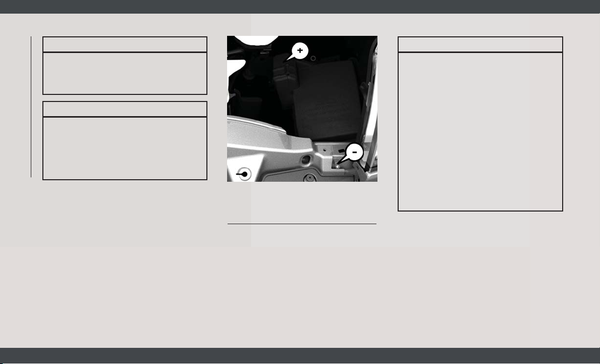
WARNING!
WARNING!
Do not attempt jump starting if the battery
is frozen. It could rupture or explode and
cause personal injury.
CAUTION!
Do not use a portable battery booster pack
or any other booster source with a system
voltage greater than 12 Volts or damage to
the battery, starter motor, alternator or
electrical system may occur.
IN CASE OF EMERGENCY
Preparations For Jump Start
The vehicle’s jump starting remote posts are
located under the hood, in the engine compartment on the driver's side.
96
Jump Starting Locations
(+) — Remote Positive Post
(-) — Remote Negative Post
The Remote Positive (+) Post is covered with
a protective cap located on the side of the
Front Power Distribution Center.
The Remote Negative (-) Post is located on
the core support closest to the front of the
vehicle.
• Take care to avoid the radiator cooling
fan whenever the hood is raised. It can
start anytime the ignition switch is ON.
You can be injured by moving fan
blades.
• Remove any metal jewelry such as rings,
watch bands and bracelets that could
make an inadvertent electrical contact.
You could be seriously injured.
• Batteries contain sulfuric acid that can
burn your skin or eyes and generate
hydrogen gas which is flammable and
explosive. Keep open flames or sparks
away from the battery.
1. Apply the parking brake, shift the automatic transmission into PARK and turn
the ignition to the OFF position.
2. Turn off the heater, radio, and all unnecessary electrical accessories.
3. If using another vehicle to jump start the
battery, park the vehicle within the
jumper cables reach, apply the parking
brake and make sure the ignition is OFF.
Page 99
WARNING!
Do not allow vehicles to touch each other
as this could establish a ground connection and personal injury could result.
Jump Starting Procedure
WARNING!
Failure to follow this jump starting procedure could result in personal injury or
property damage due to battery explosion.
CAUTION!
Failure to follow these procedures could
result in damage to the charging system of
the booster vehicle or the discharged vehicle.
Connecting The Jumper Cables
1. Connect the positive (+) end of the jumper
cable to the remote positive (+) post of the
discharged vehicle.
NOTE:
The remote positive (+) post is located in
the engine compartment on the driver's
side under the cover of the Front Power
Distribution Center.
2. Connect the opposite end of the positive
(+) jumper cable to the positive (+) post of
the booster battery.
3. Connect the negative end (-) of the jumper
cable to the negative (-) post of the
booster battery.
4. Connect the opposite end of the negative
(-) jumper cable to the remote negative (-)
post of the discharged vehicle.
NOTE:
The remote negative (-) post is located in
the front of the engine compartment on
the driver's side.
WARNING!
Do not connect the jumper cable to the
negative (-) post of the discharged battery.
WARNING!
The resulting electrical spark could cause
the battery to explode and could result in
personal injury. Only use the specific
ground point, do not use any other exposed
metal parts.
5. Start the engine in the vehicle that has the
booster battery. Let the engine idle a few
minutes and then start the engine in the
vehicle with the discharged battery.
6. Once the engine is started, disconnect the
jumper cables in the reverse sequence:
Disconnecting The Jumper Cables
1. Disconnect the negative end (-) of the
jumper cable from the remote negative (-)
post of the vehicle with the discharged
battery.
2. Disconnect the opposite end of the negative (-) jumper cable from the negative (-)
post of the booster battery.
3. Disconnect the positive end (+) of the
jumper cable from the positive (+) post of
the booster battery.
97
Page 100
4. Disconnect the opposite end of the posi-
tive (+) jumper cable from the remote
positive (+) post of the discharged
vehicle.
5. Close the cover of the Front Power Distribution Center.
If frequent jump starting is required to start
your vehicle you should have the battery and
charging system inspected at your authorized
dealer.
IN CASE OF EMERGENCY
Accessories plugged into the vehicle
power outlets draw power from the vehicle’s battery, even when not in use (i.e.,
cellular devices, etc.). Eventually, if
plugged in long enough without engine
operation, the vehicle’s battery will discharge sufficiently to degrade battery life
and/or prevent the engine from starting.
CAUTION!
Battery Location
There are two remote jump starting posts
under the hood which is the recommended
jump start location. If access to the battery is
needed, an access panel on the driver’s side
floor will allow for battery access.
IF YOUR ENGINE OVERHEATS
In any of the following situations, you can
reduce the potential for overheating by taking
the appropriate action.
• On the highways — slow down.
• In city traffic — while stopped, place the
transmission in NEUTRAL, but do not increase the engine idle speed while preventing vehicle motion with the brakes.
NOTE:
There are steps that you can take to slow
down an impending overheat condition:
• If your air conditioner (A/C) is on, turn it off.
The A/C system adds heat to the engine
cooling system and turning the A/C off can
help remove this heat.
• You can also turn the temperature control
to maximum heat, the mode control to floor
and the blower control to high. This allows
the heater core to act as a supplement to
the radiator and aids in removing heat from
the engine cooling system.
WARNING!
You or others can be badly burned by hot
engine coolant (antifreeze) or steam from
your radiator. If you see or hear steam
coming from under the hood, do not open
the hood until the radiator has had time to
cool. Never try to open a cooling system
pressure cap when the radiator or coolant
bottle is hot.
CAUTION!
Driving with a hot cooling system could
damage your vehicle. If the temperature
gauge reads HOT (H), pull over and stop
the vehicle. Idle the vehicle with the air
conditioner turned off until the pointer
drops back into the normal range. If the
pointer remains on HOT (H), and you hear
98
 Loading...