

OWNER’S MANUAL
2015
RAM TRUCK
DIESEL SUPPLEMENT
VEHICLES SOLD IN CANADA
With respect to any Vehicles Sold in Canada, the name
Chrysler Group LLC shall be deemed to be deleted and the
name Chrysler Canada Inc. used in substitution therefore.
DRIVING AND ALCOHOL
Drunken driving is one of the most frequent causes of
accidents.
Your driving ability can be seriously impaired with blood
alcohol levels far below the legal minimum. If you are
drinking, don’t drive. Ride with a designated nondrinking driver, call a cab, a friend, or use public transportation.
WARNING!
Driving after drinking can lead to an accident.
Your perceptions are less sharp, your reflexes are
slower, and your judgment is impaired when you
have been drinking. Never drink and then drive.
This manual illustrates and describes the operation of
features and equipment that are either standard or optional on this vehicle. This manual may also include a
description of features and equipment that are no longer
available or were not ordered on this vehicle. Please
disregard any features and equipment described in this
manual that are not on this vehicle.
Chrysler Group LLC reserves the right to make changes
in design and specifications, and/or make additions to or
improvements to its products without imposing any
obligation upon itself to install them on products previously manufactured.
Copyright © 2014 Chrysler Group LLC

RAM DIESEL SUPPLEMENT
RAM 1500 ..................................................................3
RAM 2500 / 3500 / 4500 / 5500 .......................................135
INDEX .....................................................................337


RAM 1500


SECTION PAGE
TABLE OF CONTENTS
1
INTRODUCTION .............................................................7
2
THINGS TO KNOW BEFORE STARTING YOUR VEHICLE ............................11
3
UNDERSTANDING YOUR INSTRUMENT PANEL . . . . . . . . . . . . . . . . . . . . . . . . . . . . . . . . . . . 15
4
STARTING AND OPERATING . . . . . . . . . . . . . . . . . . . . . . . . . . . . . . . . . . . . . . . . . . . . . . . . . . 71
5
MAINTAINING YOUR VEHICLE . . . . . . . . . . . . . . . . . . . . . . . . . . . . . . . . . . . . . . . . . . . . . . . . 97
6
MAINTENANCE SCHEDULE . . . . . . . . . . . . . . . . . . . . . . . . . . . . . . . . . . . . . . . . . . . . . . . . . . 127
1
2
3
4
5
6


INTRODUCTION
CONTENTS
! A MESSAGE FROM CHRYSLER GROUP LLC ....8
1

8INTRODUCTION
A MESSAGE FROM CHRYSLER GROUP LLC
NOTE:
Chrysler Group LLC welcomes you as a turbocharged
diesel-powered truck owner. Your diesel truck will
sound, feel, drive, and operate differently from a
gasoline-powered truck. It is important that you read and
understand this manual.
Almost 100% of the heavy trucks in the United States and
Canada are diesel-powered because of the fuel economy,
rugged durability, and high torque which permits pulling
heavy loads.
You may find that some of the starting, operating, and
maintenance procedures are different. However, they are
simple to follow and careful adherence to them will
ensure that you take full advantage of the features of this
engine.
• Some aftermarket products may cause severe engine/
transmission and/or exhaust system damage. Your
vehicle’s Powertrain Control Systems can detect and
store information about vehicle modifications that
increase horsepower and torque output such as
whether or not performance-enhancing powertrain
components, commonly referred to as downloaders,
power boxes, or performance chips have been used.
• Any chassis/suspension or tire size modifications to
the vehicle will effect the performance of the Adaptive
Cruise Control and Forward Collision Warning System.
This information cannot be erased and will stay in the
system’s memory even if the modification is removed.
This information can be retrieved by Chrysler Group
LLC, and service and repair facilities, when servicing

your vehicle. This information may be used to determine
if repair will be covered by New Vehicle Limited Warranty.
There is a probability that the use of a “performance
chip” will prohibit the engine from starting. In this
instance, the vehicle will need to be serviced by a
authorized dealer in order to return the vehicle to it’s
factory settings.
INTRODUCTION 9
1


THINGS TO KNOW BEFORE STARTING YOUR VEHICLE
CONTENTS
! REMOTE STARTING SYSTEM ..............12
▫ How To Use Remote Start ................12
2
! ENGINE BREAK-IN RECOMMENDATIONS ....13

12 THINGS TO KNOW BEFORE STARTING YOUR VEHICLE
REMOTE STARTING SYSTEM
This system uses the Remote Keyless Entry
(RKE) transmitter to start the engine conveniently from outside the vehicle while still
maintaining security. The system has a range of
approximately 300 ft (91 m).
NOTE:
• The vehicle must be equipped with an automatic
transmission to be equipped with Remote Start.
• Obstructions between the vehicle and the RKE transmitter may reduce this range.
weather. Refer to “Electronic Vehicle Information Display (EVIC)” in “Understanding Your Instrument
Panel” for further information on the “Wait To Start”
amber telltale and the pre-heat cycle.
How To Use Remote Start
All of the following conditions must be met before the
engine will remote start:
• Shift lever in PARK
• Doors closed
• Hood closed
• HAZARD switch off
• The Remote Start system will wait for the “Wait To
Start” amber telltale to extinguish before cranking the
engine. This allows time for the engine pre-heat cycle
to pre-heat the cylinder air, and is normal in cold
• BRAKE switch inactive (brake pedal not pressed)
• Battery at an acceptable charge level
• RKE PANIC button not pressed
• Fuel meets minimum requirement
THINGS TO KNOW BEFORE STARTING YOUR VEHICLE 13
ENGINE BREAK-IN RECOMMENDATIONS
• System not disabled from previous remote start event
• Vehicle security alarm not active
• Water In Fuel Indicator Light is not illuminated
• “Wait To Start” telltale is not illuminated
WARNING!
• Do not start or run an engine in a closed garage or
confined area. Exhaust gas contains Carbon Monoxide (CO) which is odorless and colorless. Carbon
Monoxide is poisonous and can cause serious injury or death when inhaled.
• Keep Remote Keyless Entry (RKE) transmitters
away from children. Operation of the Remote Start
System, windows, door locks or other controls
could cause serious injury or death.
The diesel engine does not require a break-in period due
to its construction. Normal operation is allowed, providing the following recommendations are followed:
• Warm up the engine before placing it under load.
• Do not operate the engine at idle for prolonged
periods.
• Use the appropriate transmission gear to prevent
engine lugging.
• Observe vehicle oil pressure and temperature indicators.
• Check the coolant and oil levels frequently.
• Vary throttle position at highway speeds when carry-
ing or towing significant weight.
2

14 THINGS TO KNOW BEFORE STARTING YOUR VEHICLE
NOTE: Light duty operation such as light trailer towing
or no load operation will extend the time before the
engine is at full efficiency. Reduced fuel economy and
power may be seen at this time.
The engine oil installed in the engine at the factory is a
high-quality energy conserving type lubricant. Oil
changes should be consistent with anticipated climate
conditions under which vehicle operations will occur.
The recommended viscosity and quality grades are
shown under “Fluids, Lubricants and Genuine Parts”,
under “Maintaining Your Vehicle” in this manual. NONDETERGENT OR STRAIGHT MINERAL OILS MUST
NEVER BE USED.

UNDERSTANDING YOUR INSTRUMENT PANEL
CONTENTS
! INSTRUMENT CLUSTER .................16
▫ Instrument Cluster Descriptions ............17
! INSTRUMENT CLUSTER .................29
▫ Instrument Cluster Descriptions ............30
! ELECTRONIC VEHICLE INFORMATION CENTER
(EVIC) ...............................41
▫ Electronic Vehicle Information Center (EVIC)
Displays — 3.5” Display .................42
▫ Diesel Particulate Filter (DPF) Messages ......49
▫ Diesel Exhaust Fluid (DEF) Warning Messages . .51
▫ Diesel Exhaust Fluid (DEF) Fault Warning
Messages ............................52
▫ EVIC/DID Displays.....................53
▫ Oil Life Reset .........................54
▫ Vehicle Information (Customer Information
Features) ............................56
! DRIVER INFORMATION DISPLAY (DID) ......57
▫ Driver Information Display (DID) —
7” Display ..........................196
3
16 UNDERSTANDING YOUR INSTRUMENT PANEL
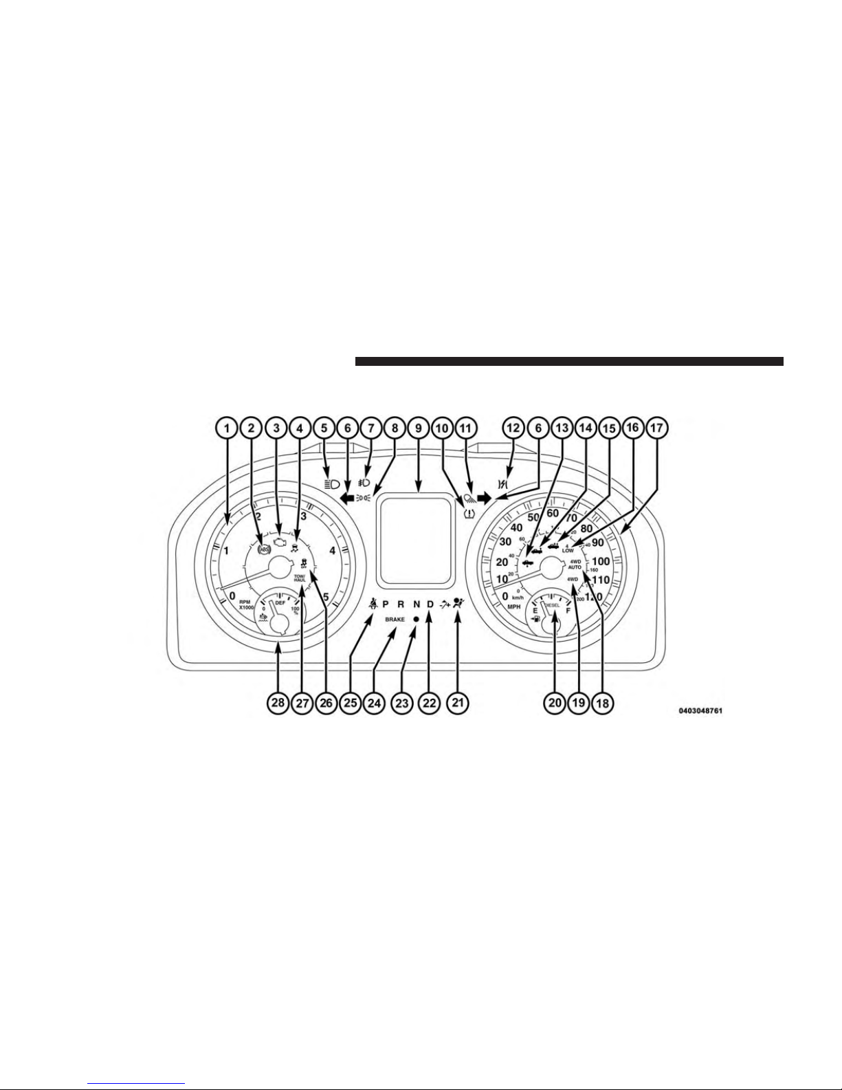
INSTRUMENT CLUSTER
Instrument Cluster Descriptions
1. Tachometer
The tachometer indicates engine speed in Revolutions
Per Minute (RPM x 1000).
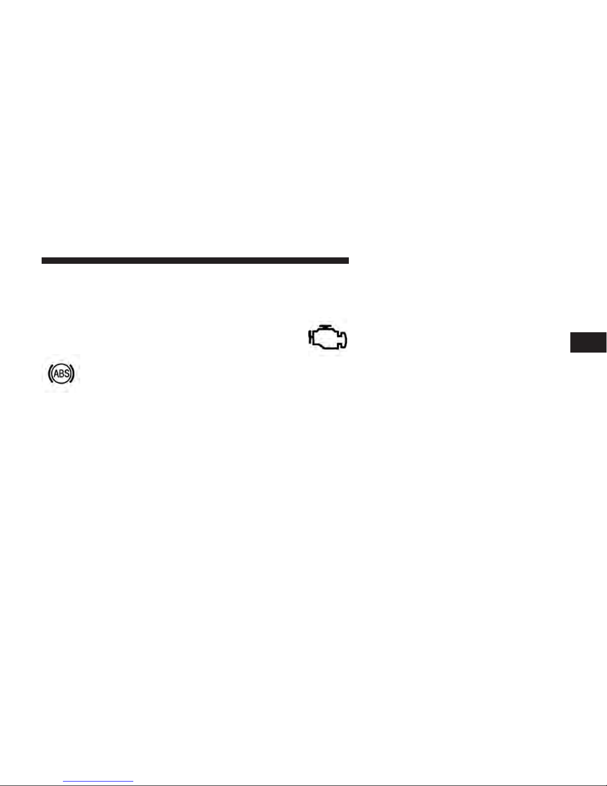
2. Anti-Lock Brake (ABS) Light
This light monitors the Anti-lock Brake System
(ABS). The light will turn on when the ignition
switch is turned to the ON/RUN position and
may stay on for as long as four seconds.
If the ABS light remains on or turns on while driving, it
indicates that the anti-lock portion of the brake system is
not functioning and that service is required. However,
the conventional brake system will continue to operate
normally if the BRAKE warning light is not on.
If the ABS light is on, the brake system should be serviced
as soon as possible to restore the benefits of anti-lock
brakes. If the ABS light does not turn on when the
UNDERSTANDING YOUR INSTRUMENT PANEL 17
ignition switch is turned to the ON/RUN position, have
the light inspected by an authorized dealer.
3. Malfunction Indicator Light (MIL)
The Malfunction Indicator Light (MIL) is part
of an Onboard Diagnostic (OBDII) system
which monitors the emissions and engine con-
trol system. If the vehicle is ready for emissions
testing, the light will come on when the ignition is first
turned on and remain on, as a bulb check, until the
engine is started. If the vehicle is not ready for emissions
testing the light will come on when the ignition is first
turned on and remain on for 15 seconds, then blink for 5
seconds, and remain on until the vehicle is started. If the
bulb does not come on during starting, have the condition investigated promptly.
If this light comes on and remains on while driving, it
suggests a potential engine control problem and the need
for system service.
3
18 UNDERSTANDING YOUR INSTRUMENT PANEL
Although your vehicle will usually be drivable and not
need towing, see your authorized dealer for service as
soon as possible.
CAUTION!
Prolonged driving with the Malfunction Indicator
Light (MIL) on could cause damage to the engine
control system. It also could affect fuel economy and
driveability. If the MIL is flashing, severe catalytic
converter damage and power loss will soon occur.
Immediate service is required.
WARNING!
A malfunctioning catalytic converter, as referenced
above, can reach higher temperatures than in normal
operating conditions. This can cause a fire if you
(Continued)
WARNING! (Continued)
drive slowly or park over flammable substances such
as dry plants, wood, cardboard, etc. This could result
in death or serious injury to the driver, occupants or
others.
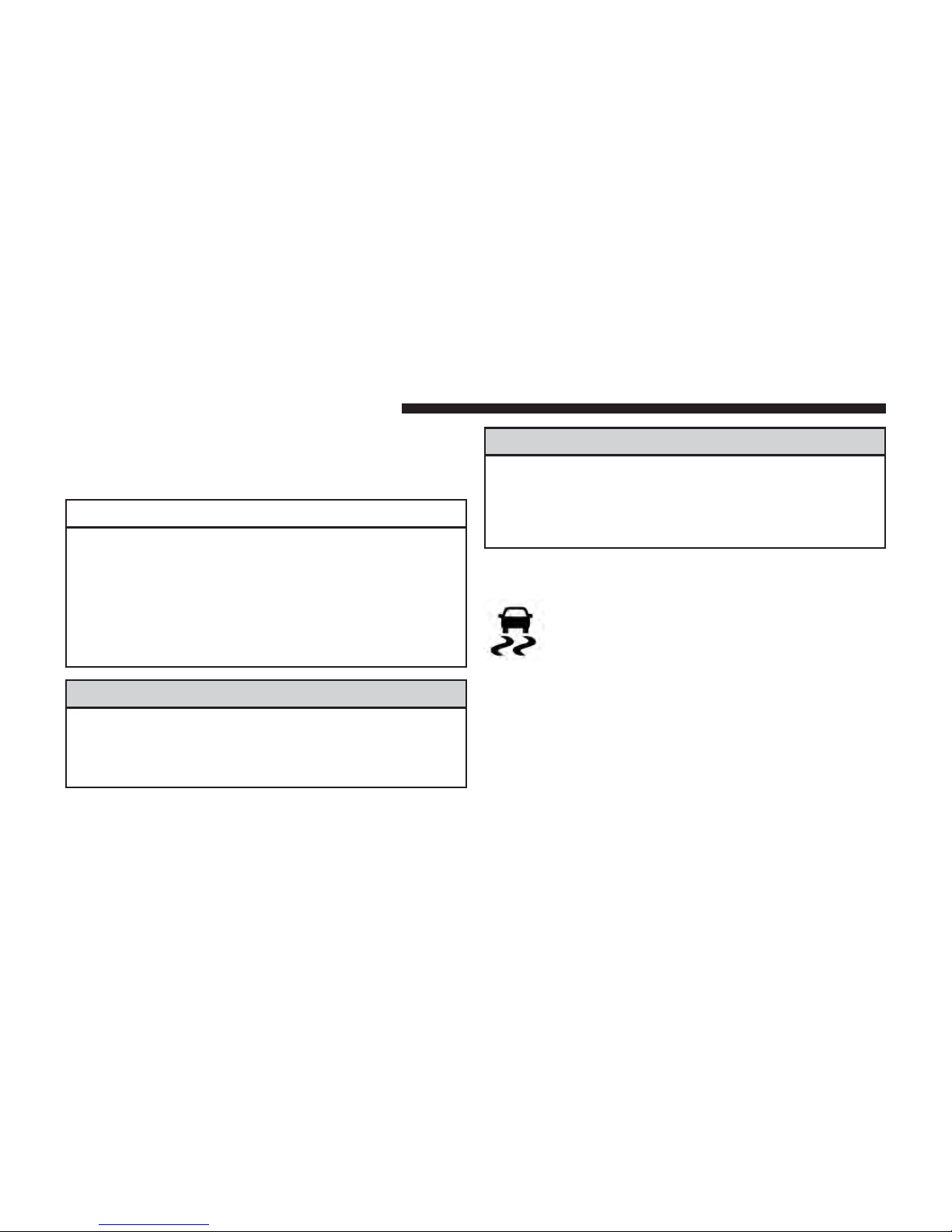
4. Electronic Stability Control (ESC) Activation/
Malfunction Indicator Light — If Equipped
The “ESC Activation/Malfunction Indicator
Light” in the instrument cluster will come on
when the ignition switch is turned to the
ON/RUN position. It should go out with the
engine running. If the “ESC Activation/Malfunction Indicator Light” comes on continuously with the engine
running, a malfunction has been detected in the ESC
system. If this light remains on after several ignition
cycles, and the vehicle has been driven several miles
(kilometers) at speeds greater than 30 mph (48 km/h), see
your authorized dealer as soon as possible to have the
problem diagnosed and corrected.
NOTE:
• The “ESC Off Indicator Light” and the “ESC
Activation/Malfunction Indicator Light” come on momentarily each time the ignition switch is turned to
ON/RUN.
• Each time the ignition is turned to ON/RUN, the ESC
system will be ON, even if it was turned off previously.
• The ESC system will make buzzing or clicking sounds
when it is active. This is normal; the sounds will stop
when ESC becomes inactive following the maneuver
that caused the ESC activation.
UNDERSTANDING YOUR INSTRUMENT PANEL 19
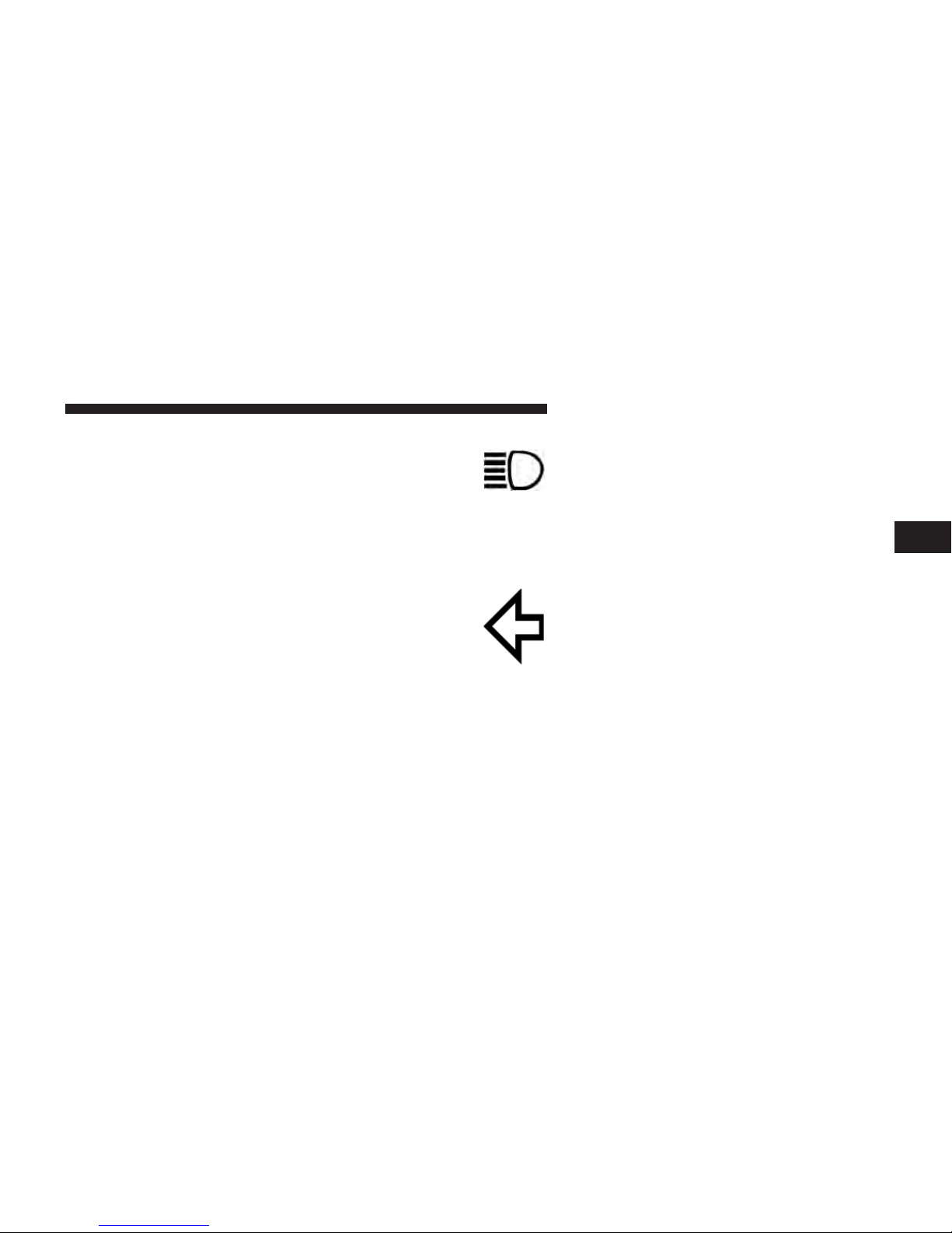
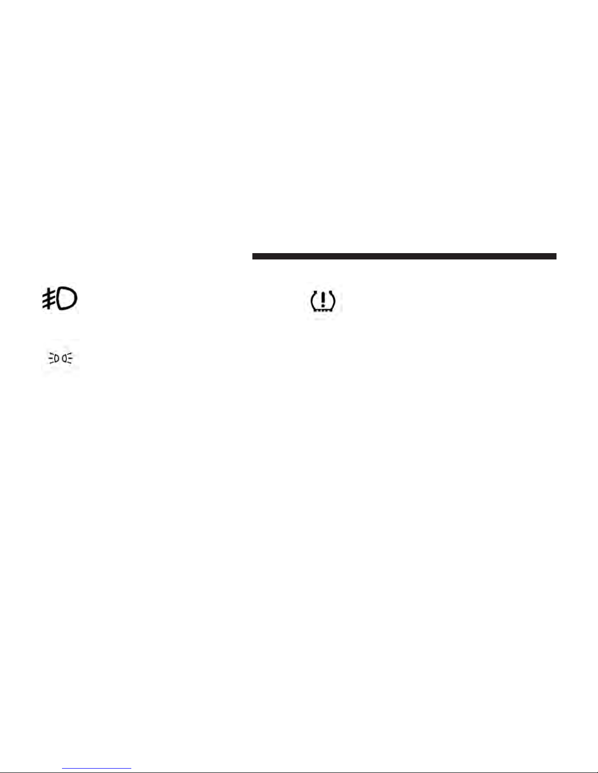
5. High Beam Indicator
This indicator shows that headlights are on
high beam. Push the multifunction lever for-
ward to switch the headlights to high beam,
and pull toward yourself (normal position) to return to
low beam.
6. Turn Signal Indicators
The arrow will flash with the exterior turn
signal when the turn signal lever is operated.
NOTE:
• A continuous chime will sound if the vehicle is driven
more than 1 mile (1.6 km) with either turn signal on.
• Check for an inoperative outside light bulb if either
indicator remains on and does not flash, or flashes at a
rapid rate.
3
20 UNDERSTANDING YOUR INSTRUMENT PANEL
7. Front Fog Light Indicator — If Equipped
10. Tire Pressure Monitoring Telltale Light
This indicator will illuminate when the front
fog lights are on.
8. Park/Headlight ON Indicator — If Equipped
This indicator will illuminate when the park
lights or headlights are turned on.
9. Electronic Vehicle Information Center (EVIC)
The Electronic Vehicle Information Center (EVIC) features an interactive display that is located in the instrument cluster. For further information, refer to “Electronic
Vehicle Information Center (EVIC)” for further
information.
Each tire, including the spare (if provided),
should be checked monthly when cold and
inflated to the inflation pressure recommended
by the vehicle manufacturer on the vehicle
placard or tire inflation pressure label. (If your vehicle
has tires of a different size than the size indicated on the
vehicle placard or tire inflation pressure label, you should
determine the proper tire inflation pressure for those
tires.)
As an added safety feature, your vehicle has been
equipped with a Tire Pressure Monitoring System
(TPMS) that illuminates a low tire pressure telltale when
one or more of your tires is significantly under-inflated.
Accordingly, when the low tire pressure telltale illuminates, you should stop and check your tires as soon as
possible, and inflate them to the proper pressure. Driving
on a significantly under-inflated tire causes the tire to
overheat and can lead to tire failure. Under-inflation also
reduces fuel efficiency and tire tread life, and may affect
the vehicle’s handling and stopping ability.
Please note that the TPMS is not a substitute for proper
tire maintenance, and it is the driver’s responsibility to
maintain correct tire pressure, even if under-inflation has
not reached the level to trigger illumination of the TPMS
low tire pressure telltale.
Your vehicle has also been equipped with a TPMS
malfunction indicator to indicate when the system is not
operating properly. The TPMS malfunction indicator is
combined with the low tire pressure telltale. When the
system detects a malfunction, the telltale will flash for
approximately one minute and then remain continuously
illuminated. This sequence will continue upon subsequent vehicle start-ups as long as the malfunction exists.
When the malfunction indicator is illuminated, the system may not be able to detect or signal low tire pressure
as intended. TPMS malfunctions may occur for a variety
of reasons, including the installation of replacement or
UNDERSTANDING YOUR INSTRUMENT PANEL 21
alternate tires or wheels on the vehicle that prevent the
TPMS from functioning properly. Always check the
TPMS malfunction telltale after replacing one or more
tires or wheels on your vehicle, to ensure that the
replacement or alternate tires and wheels allow the TPMS
to continue to function properly.
CAUTION!
The TPMS has been optimized for the original
equipment tires and wheels. TPMS pressures and
warning have been established for the tire size
equipped on your vehicle. Undesirable system operation or sensor damage may result when using replacement equipment that is not of the same size,
type, and/or style. Aftermarket wheels can cause
sensor damage. Using aftermarket tire sealants may
cause the Tire Pressure Monitoring System (TPMS)
(Continued)
3
22 UNDERSTANDING YOUR INSTRUMENT PANEL
CAUTION! (Continued)
sensor to become inoperable. After using an aftermarket tire sealant it is recommended that you take
your vehicle to an authorized dealership to have your
sensor function checked.
NOTE: The TPMS telltale is also accompanied by a “Low
Tire” message in the Electronic Vehicle Information Center (EVIC) screen indicating “Low Tire”.
11. Cargo Light
The cargo light will illuminate when the cargo
light is activated by pressing the cargo light
button on the headlight switch.
12. Electronic Throttle Control (ETC) Light
This light informs you of a problem with the
Electronic Throttle Control (ETC) system. The
light will come on when the ignition is first
turned ON and remain on briefly as a bulb check. If the
light does not come on during starting, have the system
checked by an authorized dealer.
If a problem is detected, the light will come on while the
engine is running. Cycle the ignition key when the
vehicle has completely stopped and the transmission is in
the PARK position. The light should turn off.
If the light remains lit with the engine running, your
vehicle will usually be drivable. However, see an authorized dealer for service as soon as possible. If the light is
flashing when the engine is running, immediate service is
required. You may experience reduced performance, an
elevated/rough idle or engine stall and your vehicle may
require towing.
13. Air Suspension Normal Ride Height Indicator Lamp
— If Equipped
UNDERSTANDING YOUR INSTRUMENT PANEL 23
15. Air Suspension Off-Road 2 Indicator Lamp — If
Equipped
This light will illuminate when the air suspension system
is set to the Normal Ride Height setting. For further
information, refer to “Air Suspension System” in “Starting And Operating”.
14. Air Suspension Off-Road 1 Indicator Lamp — If
Equipped
This light will illuminate when the air suspension system
is set to the Off-Road 1 setting. For further information,
refer to “Air Suspension System” in “Starting And
Operating”.
This light will illuminate when the air suspension system
is set to the Off-Road 2 setting. For further information,
refer to “Air Suspension System” in “Starting And
Operating”.
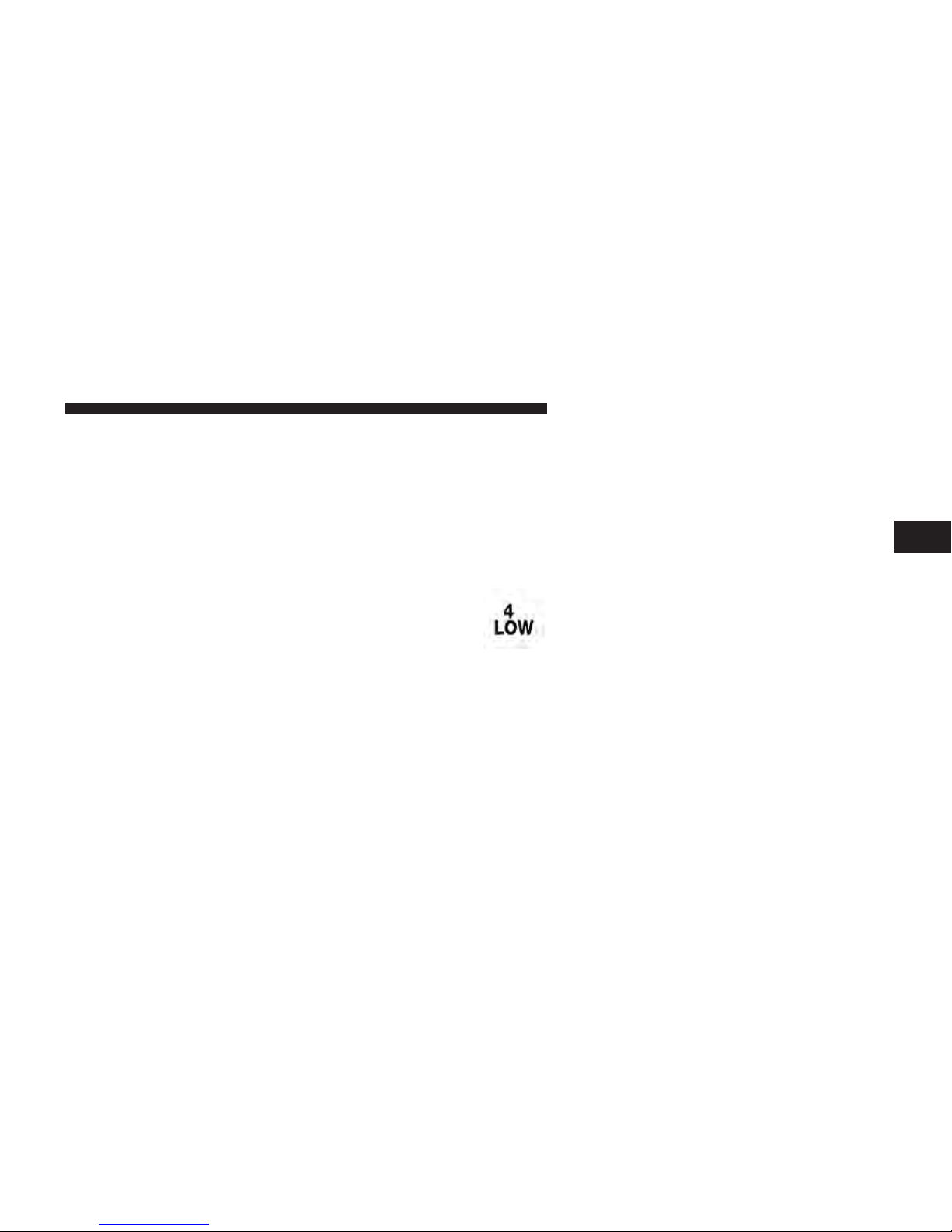
16. 4 LOW
This light alerts the driver that the vehicle is in
the four-wheel drive LOW mode. The front and
rear driveshafts are mechanically locked to-
gether forcing the front and rear wheels to
rotate at the same speed. Low range provides a greater
gear reduction ratio to provide increased torque at the
wheels.
For further information on four-wheel drive operation
and proper use, refer to “Four-Wheel Drive Operation —
If Equipped” in “Starting And Operating”.
3

24 UNDERSTANDING YOUR INSTRUMENT PANEL
17. Speedometer
The speedometer shows the vehicle speed in miles per
hour and/or kilometers per hour (mph/km/h).
18. 4WD AUTO Indicator Light — If Equipped
This light alerts the driver that the vehicle is in
the four-wheel drive auto mode, and the front
axle is engaged, but the vehicle’s power is sent
to the rear wheels. Four-wheel drive will be
automatically engaged when the vehicle senses a loss of
traction.
For further information on four-wheel drive operation
and proper use, refer to “Four-Wheel Drive Operation —
If Equipped” in “Starting And Operating”.
19. 4WD Indicator Light — If Equipped
This light alerts the driver that the vehicle is in
the four-wheel drive mode, and the front and
rear driveshafts are mechanically locked together forcing
the front and rear wheels to rotate at the same speed.
For further information on four-wheel drive operation
and proper use, refer to “Four-Wheel Drive Operation —
If Equipped” in “Starting And Operating”.
20. Fuel Gauge
Shows level of fuel in tank when ignition switch is in the
ON/RUN position.
21. Air Bag Warning Light
This light will turn on for four to eight seconds
as a bulb check when the ignition switch is first
turned to ON/RUN. If the light is either not on
during starting, stays on, or turns on while
driving, have the system inspected at an authorized
dealer as soon as possible. Refer to “Occupant Restraints”
in “Things To Know Before Starting Your Vehicle” for
further information.

22. Transmission Gear Position Indicator
UNDERSTANDING YOUR INSTRUMENT PANEL 25
24. Brake Warning Light
The Transmission Gear Position Indicator is selfcontained within the instrument cluster. It displays the
gear range of the automatic transmission.
NOTE: The highest available transmission gear is displayed in the lower right corner of the EVIC whenever
the Electronic Range Select (ERS) feature is active. Use
the +/- selector on the shift lever or steering wheel to
activate ERS. Refer to “Automatic Transmission” in
“Starting And Operating” for further information.
23. Vehicle Security Light — If Equipped
This light will flash at a fast rate for approximately 15 seconds, when the vehicle security
alarm is arming, and then will flash slowly
until the vehicle is disarmed.
This light monitors various brake functions,
including brake fluid level and parking brake
application. If the brake light turns on it may
indicate that the parking brake is applied, that
the brake fluid level is low, or that there is a problem with
the Anti-lock Brake System reservoir.
If the light remains on when the parking brake has been
disengaged, and the fluid level is at the full mark on the
master cylinder reservoir, it indicates a possible brake
hydraulic system malfunction or that a problem with the
Brake Booster has been detected by the Anti-Lock Brake
System (ABS)/Electronic Stability Control (ESC) system.
In this case, the light will remain on until the condition
has been corrected. If the problem is related to the brake
booster, the ABS pump will run when applying the brake
and a brake pedal pulsation may be felt during each stop.
3
26 UNDERSTANDING YOUR INSTRUMENT PANEL
The dual brake system provides a reserve braking capacity in the event of a failure to a portion of the hydraulic
system. A leak in either half of the dual brake system is
indicated by the Brake Warning Light, which will turn on
when the brake fluid level in the master cylinder has
dropped below a specified level.
The light will remain on until the cause is corrected.
NOTE: The light may flash momentarily during sharp
cornering maneuvers, which change fluid level conditions. The vehicle should have service performed, and
the brake fluid level checked.
If brake failure is indicated, immediate repair is necessary.
WARNING!
Driving a vehicle with the red brake light on is
dangerous. Part of the brake system may have failed.
It will take longer to stop the vehicle. You could have
a collision. Have the vehicle checked immediately.
Vehicles equipped with the ABS, are also equipped with
Electronic Brake Force Distribution (EBD). In the event of
an EBD failure, the Brake Warning Light will turn on
along with the ABS Light. Immediate repair to the ABS
system is required.
Operation of the Brake Warning Light can be checked by
turning the ignition switch from the OFF position to the
ON/RUN position. The light should illuminate for approximately two seconds. The light should then turn off
unless the parking brake is applied or a brake fault is
detected. If the light does not illuminate, have the light
inspected by an authorized dealer.
The light also will turn on when the parking brake is
applied with the ignition switch in the ON/RUN position.
NOTE: This light shows only that the parking brake is
applied. It does not show the degree of brake application.
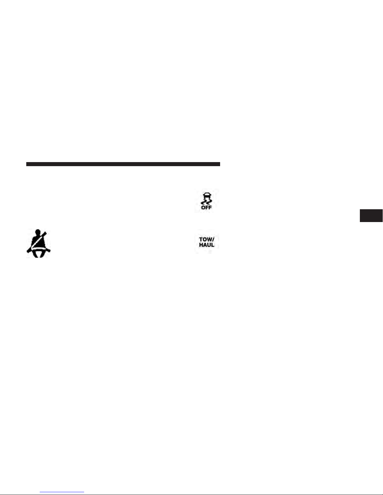
25. Seat Belt Reminder Light
UNDERSTANDING YOUR INSTRUMENT PANEL 27
26. Electronic Stability Control (ESC) OFF Indicator
Light — If Equipped
This light indicates that the Electronic Stability
Control (ESC) is in Partial Off or Full Off mode.
3
27. TOW/HAUL
When the ignition switch is first turned to
ON/RUN, this light will turn on for four to
eight seconds as a bulb check. During the bulb
check, if the driver’s seat belt is unbuckled, a
chime will sound. After the bulb check or when driving,
if the driver’s seat belt remains unbuckled, the seat belt
reminder light will flash or remain on continuously. Refer
to “Occupant Restraints” in “Things To Know Before
Starting Your Vehicle” for further information.
The TOW HAUL button is located on the center
stack upper switch bank. This light will illuminate when TOW HAUL mode is selected.
28. DEF Gauge
The DEF Gauge displays the actual level of Diesel
Exhaust Fluid in the DEF tank. Diesel Exhaust Fluid
(DEF) is required to maintain normal vehicle operation
and emissions compliance. More information is available
in the Electronic Vehicle Information (EVIC) or Driver
Information Display (DID) section under the heading of
Diesel Exhaust Fluid (DEF) Warning Messages.

28 UNDERSTANDING YOUR INSTRUMENT PANEL
NOTE:
The gauge may take up to five seconds to update after
adding a gallon or more of Diesel Exhaust Fluid (DEF) to
the DEF tank. If you have a fault related to the DEF
system, the gauge may not update to the new level. See
your authorized dealer for service.
The DEF gauge may also not immediately update after a
refill if the temperature of the DEF fluid is below 12F
(-11C). The DEF line heater will possibly warm up the
DEF fluid and allow the gauge to update after a period of
run time. Under very cold conditions, it is possible that
the gauge may not reflect the new fill level for several
drives.

INSTRUMENT CLUSTER
UNDERSTANDING YOUR INSTRUMENT PANEL 29
3

30 UNDERSTANDING YOUR INSTRUMENT PANEL
Instrument Cluster Descriptions
1. Tachometer
The tachometer indicates engine speed in Revolutions
Per Minute (RPM x 1000).
If the ABS light remains on or turns on while driving, it
indicates that the anti-lock portion of the brake system is
not functioning and that service is required. However,
the conventional brake system will continue to operate
normally if the BRAKE warning light is not on.
CAUTION!
Do not operate the engine with the tachometer
pointer at high RPM for extended periods. Engine
operation over 3200 RPM (Redline) can result in
significant damage that will not be covered under
warranty.
2. Anti-Lock Brake (ABS) Light
This light monitors the Anti-lock Brake System
(ABS). The light will turn on when the ignition
switch is turned to the ON/RUN position and
may stay on for as long as four seconds.
If the ABS light is on, the brake system should be serviced
as soon as possible to restore the benefits of anti-lock
brakes. If the ABS light does not turn on when the
ignition switch is turned to the ON/RUN position, have
the light inspected by an authorized dealer.
3. Malfunction Indicator Light (MIL)
The Malfunction Indicator Light (MIL) is part
of an Onboard Diagnostic (OBDII) system
which monitors the emissions and engine con-
trol system. If the vehicle is ready for emissions
testing, the light will come on when the ignition is first
turned on and remain on, as a bulb check, until the
engine is started. If the vehicle is not ready for emissions

testing the light will come on when the ignition is first
turned on and remain on for 15 seconds, then blink for 5
seconds, and remain on until the vehicle is started. If the
bulb does not come on during starting, have the condition investigated promptly.
If this light comes on and remains on while driving, it
suggests a potential engine control problem and the need
for system service.
UNDERSTANDING YOUR INSTRUMENT PANEL 31
CAUTION!
Prolonged driving with the Malfunction Indicator
Light (MIL) on could cause damage to the engine
control system. It also could affect fuel economy and
driveability. If the MIL is flashing, severe catalytic
converter damage and power loss will soon occur.
Immediate service is required.
3
Although your vehicle will usually be drivable and not
need towing, see your authorized dealer for service as
soon as possible.
WARNING!
A malfunctioning catalytic converter, as referenced
above, can reach higher temperatures than in normal
operating conditions. This can cause a fire if you
drive slowly or park over flammable substances such
as dry plants, wood, cardboard, etc. This could result
in death or serious injury to the driver, occupants or
others.

32 UNDERSTANDING YOUR INSTRUMENT PANEL
4. Turn Signal Indicators
5. Engine Coolant Temperature
The arrow will flash with the exterior turn
signal when the turn signal lever is operated.
NOTE:
• A continuous chime will sound if the vehicle is driven
more than 1 mile (1.6 km) with either turn signal on.
• Check for an inoperative outside light bulb if either
indicator remains on and does not flash, or flashes at a
rapid rate.
This gauge shows the engine coolant temperature. The
gauge pointer will likely show higher temperatures when
driving in hot weather, up mountain grades, or in heavy
stop and go traffic. If the red Warning Light turns on
while driving, safely bring the vehicle to a stop, and turn
off the engine. DO NOT operate the vehicle until the
cause is corrected.
CAUTION!
Driving with a hot engine cooling system could
damage your vehicle. If the temperature gauge reads
“H” pull over and stop the vehicle. Idle the vehicle
with the air conditioner turned off until the pointer
drops back into the normal range. If the pointer
remains on the “H” and you hear continuous chimes,
turn the engine off immediately and call an authorized dealer for service.

WARNING!
A hot engine cooling system is dangerous. You or
others could be badly burned by steam or boiling
coolant. You may want to call an authorized dealer
for service if your vehicle overheats. If you decide to
look under the hood yourself, see “Maintaining Your
Vehicle.” Follow the warnings under the “Cooling
System Pressure Cap” paragraph.
6. Brake Warning Light
This light monitors various brake functions,
including brake fluid level and parking brake
application. If the brake light turns on it may
indicate that the parking brake is applied, that
the brake fluid level is low, or that there is a problem with
the Anti-lock Brake System reservoir.
If the light remains on when the parking brake has been
disengaged, and the fluid level is at the full mark on the
UNDERSTANDING YOUR INSTRUMENT PANEL 33
master cylinder reservoir, it indicates a possible brake
hydraulic system malfunction or that a problem with the
Brake Booster has been detected by the Anti-Lock Brake
System (ABS)/Electronic Stability Control (ESC) system.
In this case, the light will remain on until the condition
has been corrected. If the problem is related to the brake
booster, the ABS pump will run when applying the brake
and a brake pedal pulsation may be felt during each stop.
The dual brake system provides a reserve braking capacity in the event of a failure to a portion of the hydraulic
system. A leak in either half of the dual brake system is
indicated by the Brake Warning Light, which will turn on
when the brake fluid level in the master cylinder has
dropped below a specified level.
The light will remain on until the cause is corrected.
3

34 UNDERSTANDING YOUR INSTRUMENT PANEL
NOTE: The light may flash momentarily during sharp
cornering maneuvers, which change fluid level conditions. The vehicle should have service performed, and
the brake fluid level checked.
If brake failure is indicated, immediate repair is necessary.
Operation of the Brake Warning Light can be checked by
turning the ignition switch from the OFF position to the
ON/RUN position. The light should illuminate for approximately two seconds. The light should then turn off
unless the parking brake is applied or a brake fault is
detected. If the light does not illuminate, have the light
inspected by an authorized dealer.
WARNING!
Driving a vehicle with the red brake light on is
dangerous. Part of the brake system may have failed.
It will take longer to stop the vehicle. You could have
a collision. Have the vehicle checked immediately.
Vehicles equipped with the ABS, are also equipped with
Electronic Brake Force Distribution (EBD). In the event of
an EBD failure, the Brake Warning Light will turn on
along with the ABS Light. Immediate repair to the ABS
system is required.
The light also will turn on when the parking brake is
applied with the ignition switch in the ON/RUN position.
NOTE: This light shows only that the parking brake is
applied. It does not show the degree of brake application.
7. High Beam Indicator
This indicator shows that headlights are on
high beam. Push the multifunction lever for-
ward to switch the headlights to high beam,
and pull toward yourself (normal position) to return to
low beam.

8. Seat Belt Reminder Light
When the ignition switch is first turned to
ON/RUN, this light will turn on for four to
eight seconds as a bulb check. During the bulb
check, if the driver’s seat belt is unbuckled, a
chime will sound. After the bulb check or when driving,
if the driver’s seat belt remains unbuckled, the seat belt
reminder light will flash or remain on continuously. Refer
to “Occupant Restraints” in “Things To Know Before
Starting Your Vehicle” for further information.
9. Air Bag Warning Light
This light will turn on for four to eight seconds
as a bulb check when the ignition switch is first
turned to ON/RUN. If the light is either not on
during starting, stays on, or turns on while
driving, have the system inspected at an authorized
UNDERSTANDING YOUR INSTRUMENT PANEL 35
dealer as soon as possible. Refer to “Occupant Restraints”
in “Things To Know Before Starting Your Vehicle” for
further information.
10. Engine Oil Pressure
The pointer should always indicate some oil pressure
when the engine is running. A continuous high or low
reading under normal driving conditions may indicate a
lubrication system malfunction. Immediate service
should be obtained from an authorized dealer.
If the gauge pointer moves to either extreme of the gauge,
the Check Gauges indicator will illuminate and a single
chime will sound.
11. Speedometer
The speedometer shows the vehicle speed in miles per
hour and/or kilometers per hour (mph/km/h).
3

36 UNDERSTANDING YOUR INSTRUMENT PANEL
12. Park/Headlight ON Indicator — If Equipped
16. Tire Pressure Monitoring Telltale Light
This indicator will illuminate when the park
lights or headlights are turned on.
13. Cargo Light
The cargo light will illuminate when the cargo
light is activated by pressing the cargo light
button on the headlight switch.
14. Fuel Gauge
Shows level of fuel in tank when ignition switch is in the
ON/RUN position.
15. Vehicle Security Light — If Equipped
This light will flash at a fast rate for approxi-
mately 15 seconds, when the vehicle security
alarm is arming, and then will flash slowly
until the vehicle is disarmed.
Each tire, including the spare (if provided),
should be checked monthly when cold and
inflated to the inflation pressure recommended
by the vehicle manufacturer on the vehicle
placard or tire inflation pressure label. (If your vehicle
has tires of a different size than the size indicated on the
vehicle placard or tire inflation pressure label, you should
determine the proper tire inflation pressure for those
tires.)
As an added safety feature, your vehicle has been
equipped with a Tire Pressure Monitoring System
(TPMS) that illuminates a low tire pressure telltale when
one or more of your tires is significantly under-inflated.
Accordingly, when the low tire pressure telltale illuminates, you should stop and check your tires as soon as
possible, and inflate them to the proper pressure. Driving
on a significantly under-inflated tire causes the tire to
overheat and can lead to tire failure. Under-inflation also

reduces fuel efficiency and tire tread life, and may affect
the vehicle’s handling and stopping ability.
Please note that the TPMS is not a substitute for proper
tire maintenance, and it is the driver’s responsibility to
maintain correct tire pressure, even if under-inflation has
not reached the level to trigger illumination of the TPMS
low tire pressure telltale.
Your vehicle has also been equipped with a TPMS
malfunction indicator to indicate when the system is not
operating properly. The TPMS malfunction indicator is
combined with the low tire pressure telltale. When the
system detects a malfunction, the telltale will flash for
approximately one minute and then remain continuously
illuminated. This sequence will continue upon subsequent vehicle start-ups as long as the malfunction exists.
When the malfunction indicator is illuminated, the system may not be able to detect or signal low tire pressure
as intended. TPMS malfunctions may occur for a variety
of reasons, including the installation of replacement or
UNDERSTANDING YOUR INSTRUMENT PANEL 37
alternate tires or wheels on the vehicle that prevent the
TPMS from functioning properly. Always check the
TPMS malfunction telltale after replacing one or more
tires or wheels on your vehicle, to ensure that the
replacement or alternate tires and wheels allow the TPMS
to continue to function properly.
CAUTION!
The TPMS has been optimized for the original
equipment tires and wheels. TPMS pressures and
warning have been established for the tire size
equipped on your vehicle. Undesirable system operation or sensor damage may result when using replacement equipment that is not of the same size,
type, and/or style. Aftermarket wheels can cause
sensor damage. Using aftermarket tire sealants may
cause the Tire Pressure Monitoring System (TPMS)
(Continued)
3

38 UNDERSTANDING YOUR INSTRUMENT PANEL
CAUTION! (Continued)
sensor to become inoperable. After using an aftermarket tire sealant it is recommended that you take
your vehicle to an authorized dealership to have your
sensor function checked.
NOTE: The TPMS telltale is also accompanied by a “Low
Tire” message in the Driver Information Display (DID)
screen indicating “Low Tire”.
17. Front Fog Light Indicator — If Equipped
This indicator will illuminate when the front
fog lights are on.
18. Driver Information Display (DID)
The Driver Information Display (DID) features an interactive display that is located in the instrument cluster.
For further information, refer to “Driver Information
Display (DID)” in this section.
19. Transmission Gear Position Indicator
The Transmission Gear Position Indicator is selfcontained within the instrument cluster. It displays the
gear range of the automatic transmission.
NOTE: The highest available transmission gear is displayed in the lower right corner of the DID whenever the
Electronic Range Select (ERS) feature is active. Use the
+/- selector on the shift lever or steering wheel to activate
ERS. Refer to “Automatic Transmission” in “Starting And
Operating” for further information.

20. Driver Information Display (DID) Menu
Driver Information Display (DID) features an interactive
display of the main menu’s that is located in the instrument cluster. For further information, refer to “Driver
Information Display (DID)” in this section.
21. Electronic Stability Control (ESC) OFF Indicator
Light — If Equipped
This light indicates that the Electronic Stability
Control (ESC) is in Partial Off or Full Off mode.
22. TOW/HAUL
The TOW HAUL button is located on the center
stack upper switch bank. This light will illuminate when TOW HAUL mode is selected.
UNDERSTANDING YOUR INSTRUMENT PANEL 39
23. Electronic Stability Control (ESC) Activation/
Malfunction Indicator Light — If Equipped
The “ESC Activation/Malfunction Indicator
Light” in the instrument cluster will come on
when the ignition switch is turned to the
ON/RUN position. It should go out with the
engine running. If the “ESC Activation/Malfunction Indicator Light” comes on continuously with the engine
running, a malfunction has been detected in the ESC
system. If this light remains on after several ignition
cycles, and the vehicle has been driven several miles
(kilometers) at speeds greater than 30 mph (48 km/h), see
your authorized dealer as soon as possible to have the
problem diagnosed and corrected.
3

40 UNDERSTANDING YOUR INSTRUMENT PANEL
NOTE:
• The “ESC Off Indicator Light” and the “ESC
Activation/Malfunction Indicator Light” come on momentarily each time the ignition switch is turned to
ON/RUN.
• Each time the ignition is turned to ON/RUN, the ESC
system will be ON, even if it was turned off previously.
• The ESC system will make buzzing or clicking sounds
when it is active. This is normal; the sounds will stop
when ESC becomes inactive following the maneuver
that caused the ESC activation.
24. DEF Gauge
The DEF Gauge displays the actual level of Diesel
Exhaust Fluid in the DEF tank. Diesel Exhaust Fluid
(DEF) is required to maintain normal vehicle operation
and emissions compliance. More information is available
in the Electronic Vehicle Information (EVIC) or Driver
Information Display (DID) section under the heading of
Diesel Exhaust Fluid (DEF) Warning Messages.
NOTE:
• The gauge may take up to five seconds to update after
adding a gallon or more of Diesel Exhaust Fluid (DEF)
to the DEF tank. If you have a fault related to the DEF
system, the gauge may not update to the new level. See
your authorized dealer for service.
• The DEF gauge may also not immediately update after
a refill if the temperature of the DEF fluid is below 12F
(-11C). The DEF line heater will possibly warm up the
DEF fluid and allow the gauge to update after a period
of run time. Under very cold conditions, it is possible
that the gauge may not reflect the new fill level for
several drives.

ELECTRONIC VEHICLE INFORMATION CENTER
(EVIC)
The Electronic Vehicle Information Center (EVIC) features a driver-interactive display that is located in the
instrument cluster.
Electronic Vehicle Information Center (EVIC)
UNDERSTANDING YOUR INSTRUMENT PANEL 41
This system conveniently allows the driver to select a
variety of useful information by pressing the switches
mounted on the steering wheel.
Refer to “Electronic Vehicle Information Center – If
Equipped” in the Owner’s Manual for further information.
3

42 UNDERSTANDING YOUR INSTRUMENT PANEL
Electronic Vehicle Information Center (EVIC)
Displays — 3.5” Display
The EVIC displays are located in the center portion of the
cluster and consists of seven sections:
1. Compass Display
Displays the current direction. For further information,
refer to “Compass Settings” under “Customer Programmable Features — Uconnect® 5.0/8.4 Settings”.
2. Temperature Display
Displays the temperature in degrees Celsius or degrees
Fahrenheit.
3. Main Screen
Displays main menu, sub-menus, settings.

4. EVIC White Telltales
• Electronic Speed Control Ready
This light will turn on when the electronic
speed control is ON. For further information,
refer to “Electronic Speed Control” in “Understanding The Features Of Your Vehicle.”
• Electronic Speed Control SET
This light will turn on when the electronic
speed control is SET. For further information,
refer to “Electronic Speed Control” in “Understanding The Features Of Your Vehicle.”
• ERS Gear Limit
The highest available transmission gear is displayed in
the lower right corner of the Electronic Vehicle Information Center (EVIC) whenever the Electronic Range Select
(ERS) feature is active. Use the +/- selector on the shift
lever or steering wheel to activate ERS. Refer to “Automatic Transmission” in “Starting And Operating” for
further information.
UNDERSTANDING YOUR INSTRUMENT PANEL 43
5. EVIC Amber Telltales
• Low Fuel Telltale
When the fuel level reaches approximately 3.0 gal
(11.0 L) this light will turn on, and remain on until
fuel is added.
• Windshield Washer Fluid Low Indicator
This telltale will turn on to indicate the windshield washer fluid is low.
• Low Coolant Level Indicator
This telltale will turn on to indicate the vehicle
coolant level is low.
• Transmission Temperature Warning Telltale
This telltale indicates that the transmission
fluid temperature is running hot. This may
occur with severe usage, such as trailer towing.
3

44 UNDERSTANDING YOUR INSTRUMENT PANEL
If this telltale turns on, safely pull over and stop the
vehicle. Then, shift the transmission into PARK and run
the engine at idle or faster until the light turns off.
CAUTION!
Continuous driving with the Transmission Temperature Warning Light illuminated will eventually cause
severe transmission damage or transmission failure.
WARNING!
If you continue operating the vehicle when the
Transmission Temperature Warning Light is illuminated you could cause the fluid to boil over, come in
contact with hot engine or exhaust components and
cause a fire.
• Air Suspension Payload Protection Telltale — If
Equipped
This telltale will turn on to indicate that the
maximum payload may have been exceeded or
load leveling cannot be achieved at its current
ride height.
Protection Mode will automatically be selected in
order to “protect” the air suspension system, air
suspension adjustment is limited due to payload.
• Water In Fuel Indicator Light — Diesel Only
The “Water In Fuel Indicator Light” will illuminate when there is water detected in the fuel
filters. If this light remains on, DO NOT start
the vehicle before you drain the water from the
fuel filters to prevent engine damage. Refer to “Maintenance Procedures/Draining Fuel/Water Separator Filters” in “Maintaining Your Vehicle” for further
information.

• Wait To Start Light
The “Wait To Start” telltale will illuminate for
approximately two seconds when the ignition is
turned to the RUN position. It’s duration may be longer
based on colder operating conditions. Vehicle will not
initiate start until telltale is out. Refer to “Starting Procedures” in “Starting And Operating” for further
information.
NOTE: The “Wait To Start” telltale may not illuminate if
the intake manifold temperature is warm enough.
• Low Diesel Exhaust Fluid Light
This telltale will turn on to indicate the Diesel
Exhaust Fluid (DEF) is low.
UNDERSTANDING YOUR INSTRUMENT PANEL 45
6. EVIC Red Telltales
• Door Ajar
This light will turn on to indicate that one or
more doors may be ajar.
3
• Oil Pressure Warning Light
This telltale indicates low engine oil pressure. If
the light turns on while driving, stop the vehicle
and shut off the engine as soon as possible. A chime will
sound when this light turns on.
Do not operate the vehicle until the cause is corrected.
This light does not show how much oil is in the engine.
The engine oil level must be checked under the hood.

46 UNDERSTANDING YOUR INSTRUMENT PANEL
• Oil Temperature Warning Light
This telltale indicates engine oil temperature is
high. If the light turns on while driving, stop
the vehicle and shut off the engine as soon as
possible.
• Charging System Light
This light shows the status of the electrical charg-
ing system. If the light stays on or comes on while
driving, turn off some of the vehicle’s non-essential
electrical devices or increase engine speed (if at idle). If
the charging system light remains on, it means that the
vehicle is experiencing a problem with the charging
system. Obtain SERVICE IMMEDIATELY. See an authorized dealer.
If jump starting is required, refer to “Jump Starting
Procedures” in “What To Do In Emergencies”.
• Electronic Throttle Control (ETC) Light
This light informs you of a problem with the
Electronic Throttle Control (ETC) system. The
light will come on when the ignition is first
turned ON and remain on briefly as a bulb
check. If the light does not come on during starting, have
the system checked by an authorized dealer.
If a problem is detected, the light will come on while the
engine is running. Cycle the ignition key when the
vehicle has completely stopped and the transmission is in
the PARK position. The light should turn off.
If the light remains lit with the engine running, your
vehicle will usually be drivable. However, see an authorized dealer for service as soon as possible. If the light is
flashing when the engine is running, immediate service is
required. You may experience reduced performance, an
elevated/rough idle or engine stall and your vehicle may
require towing.

• Engine Temperature Warning Light
This light warns of an overheated engine condition. As temperatures rise and the gauge ap-
proaches H, this indicator will illuminate and a
single chime will sound after reaching a set threshold.
Further overheating will cause the temperature gauge to
pass H, a continuous chime will occur until the engine is
allowed to cool.
If the light turns on while driving, safely pull over and
stop the vehicle. If the A/C system is on, turn it off. Also,
shift the transmission into PARK and idle the vehicle. If
the temperature reading does not return to normal, turn
the engine off immediately and call for service. Refer to
“If Your Engine Overheats” in “What To Do In Emergencies” for further information.
UNDERSTANDING YOUR INSTRUMENT PANEL 47
• Electric Power Steering Malfunction Warning Light
This telltale is on when the Electric Power
Steering is not operating and needs service.
• Trailer Brake Disconnected Warning Light
This telltale is on when the Trailer Brake has
been disconnected.
7. Audio/Phone Information And Sub-menu Information
Whenever there are sub-menus available, the position
within the sub-menu is shown here.
3

48 UNDERSTANDING YOUR INSTRUMENT PANEL
The main display area will normally display the main
menu or the screens of a selected feature of the main
menu. The main display area also displays “pop up”
messages that consist of approximately 60 possible warning or information messages. These pop up messages fall
into several categories:
• Five Second Stored Messages
When the appropriate conditions occur, this type of
message takes control of the main display area for five
seconds and then returns to the previous screen. Most of
the messages of this type are then stored (as long as the
condition that activated it remains active) and can be
reviewed from the “Messages” main menu item. As long
as there is a stored message, an “i” will be displayed in
the EVIC’s compass/outside temp line. Examples of this
message type are “Right Front Turn Signal Lamp Out”
and “Low Tire Pressure”.
• Unstored Messages
This message type is displayed indefinitely or until the
condition that activated the message is cleared. Examples
of this message type are “Turn Signal On” (if a turn signal
is left on) and “Lights On” (if driver leaves the vehicle).
• Unstored Messages Until RUN
These messages deal primarily with the Remote Start
feature. This message type is displayed until the ignition
is in the RUN state. Examples of this message type are
“Remote Start Aborted - Door Ajar” and “Press Brake
Pedal and Push Button to Start”.
• Five Second Unstored Messages
When the appropriate conditions occur, this type of
message takes control of the main display area for five
seconds and then returns to the previous screen. An
example of this message type is “Automatic High Beams
On”.

Diesel Particulate Filter (DPF) Messages
This engine meets all required diesel engine emissions
standards. To achieve these emissions standards, your
vehicle is equipped with a state-of-the-art engine and
exhaust system. These systems are seamlessly integrated
into your vehicle and managed by the Powertrain Control Module (PCM). The PCM manages engine combustion to allow the exhaust system’s catalyst to trap and
burn Particulate Matter (PM) pollutants, with no input or
interaction on your part.
WARNING!
A hot exhaust system can start a fire if you park over
materials that can burn. Such materials might be
grass or leaves coming into contact with your exhaust
system. Do not park or operate your vehicle in areas
where your exhaust system can contact anything that
can burn.
UNDERSTANDING YOUR INSTRUMENT PANEL 49
Your vehicle has the ability to alert you to additional
maintenance required on your vehicle or engine. Refer to
the following messages that may be displayed on your
Electronic Vehicle Information Center (EVIC):
• Exhaust Filter XX% Full Safely Drive at Highway
Speeds to Remedy — This message will be displayed
in the Electronic Vehicle Information Center (EVIC) if
the exhaust particulate filter reaches 80% of its maximum storage capacity. Under conditions of exclusive
short duration and low speed driving cycles, your
diesel engine and exhaust after-treatment system may
never reach the conditions required to cleanse the filter
to remove the trapped PM. If this occurs, the “Exhaust
Filter XX% Full Safely Drive at Highway Speeds to
Remedy” message will be displayed in the EVIC. If
this message is displayed, you will hear one chime to
assist in alerting you of this condition. By simply
driving your vehicle at highway speeds for up to 20
3

50 UNDERSTANDING YOUR INSTRUMENT PANEL
minutes, you can remedy the condition in the particulate filter system and allow your diesel engine and
exhaust after-treatment system to cleanse the filter to
remove the trapped PM and restore the system to
normal operating condition.
• Exhaust System — Regeneration In Process Exhaust
Filter XX% Full — This message indicates that the
Diesel Particulate Filter (DPF) is self-cleaning. Maintain your current driving condition until regeneration
is completed.
• Exhaust System — Regeneration Completed — This
message indicates that the Diesel Particulate Filter
(DPF) self-cleaning is completed. If this message is
displayed, you will hear one chime to assist in alerting
you of this condition.
• Exhaust Service Required — See Dealer Now — This
messages indicates regeneration has been disabled due
to a system malfunction. At this point the engine
Powertrain Control Module (PCM) will register a fault
code, the instrument panel will display a MIL light.
CAUTION!
See your authorized dealer, as damage to the exhaust
system could occur soon with continued operation.
• Exhaust Filter Full — Power Reduced See Dealer —
This message indicates the PCM has derated the
engine to limit the likelihood of permanent damage to
the after-treatment system. If this condition is not
corrected and a dealer service is not performed, extensive exhaust after-treatment damage can occur. To
correct this condition it will be necessary to have your
vehicle serviced by your local authorized dealer.

CAUTION!
See your authorized dealer, as damage to the exhaust
system could occur soon with continued operation.
Diesel Exhaust Fluid (DEF) Warning Messages
Your vehicle will begin displaying warning messages
when the DEF level reaches a driving range of approximately 500 miles (800 km). If the following warning
message sequence is ignored, your vehicle may not
restart unless DEF is added with in the displayed mileage
shown in the Cluster message.
• Engine Will Not Restart in XXXX mi DEF Low Refill
Soon — This message will display when DEF driving
range is less than 500 miles, DEF fluid top off is
required with in the displayed mileage. The message
will be displayed in the cluster during vehicle start up
with the current allowed mileage and accompanied by
UNDERSTANDING YOUR INSTRUMENT PANEL 51
a single chime. The remaining mileage can be pulled
up anytime by way of the “Messages” list within the
EVIC/DID
• Engine Will Not Restart in XXXX mi Refill DEF —
This message will display when DEF driving range is
less than 200 miles. It is also displayed at 150 miles and
100 miles. DEF fluid top off is required with in the
displayed mileage. The message will be displayed in
the EVIC/DID during vehicle start up with an updated distance mileage, and it will be accompanied by
a single chime. Stating at 100 miles, remaining range
will be continuously displayed while operating the
vehicle. Chimes will also accompany the 75, 50 and 25
mile remaining distances. The DEF Low telltale will be
on continuously until DEF fluid is topped off.
• Engine Will Not Restart Refill DEF — This message
will display when the DEF driving range is less than 1
mile, DEF fluid top off is required or the engine will
not restart. The message will be displayed in the
3

52 UNDERSTANDING YOUR INSTRUMENT PANEL
EVIC/DID during vehicle start up, and it will be
accompanied by a single chime. The DEF Low telltale
will be illuminated continuously until DEF fluid tank
is filled with a minimum of two gallons of DEF.
authorized dealer and have your vehicle serviced
immediately. If not corrected in 50 miles, vehicle will
enter the “Engine Will not restart in XXXmi Service
DEF See dealer” warning stage and message.
Diesel Exhaust Fluid (DEF) Fault Warning
Messages
There are different messages which are displayed if the
vehicle detects that the DEF system has been filled with
a fluid other than DEF, has experienced component
failures, or when tampering has been detected.
When the DEF system needs to be serviced the following
warnings will display:
• Service DEF System See Dealer — This message will
display when the fault is initially detected and each
time the vehicle is started. The message will be accompanied by a single chime and the Malfunction Indicator Light. We recommend you drive to your nearest
• Engine Will Not Restart in XXX mi Service DEF See
Dealer — This message is first displayed if the fault
detected is not serviced after 50 miles of operation. It is
also displayed at 150 miles 125 miles and 100 miles.
System service is required within the displayed mileage. The message will be displayed during vehicle
start up with an updated distance mileage, and it will
be accompanied by a single chime. Starting at 100
miles, remaining range will be continuously displayed
while operating the vehicle. Chimes will also accompany the 75, 50 and 25 mile remaining distances. We
recommend you drive to your nearest authorized
dealer and have your vehicle serviced immediately.

• Engine Will Not Restart Service DEF System See
Dealer — This message will display if DEF system
issue detected is not serviced during the allowed
period. Your engine will not restart unless your vehicle
is serviced by your authorized dealer. This message
will be displayed when under 1 mile until engine will
not start and each time the vehicle is started, and will
be continuously displayed. The message will be accompanied by a single chime. Your Malfunction Indicator Light will be continuously illumined. We highly
recommend you drive to your nearest authorized
dealer if the message appears while engine is running.
UNDERSTANDING YOUR INSTRUMENT PANEL 53
chime. Your Malfunction Indicator Light will be continuously illuminated. If the message appears and you
can not start the engine, we recommend you have your
vehicle towed to your nearest authorized dealer immediately.
EVIC/DID Displays
When the appropriate conditions exist, the EVIC/DID
displays the following messages:
• System Setup Unavailable – Vehicle Not in Park
• System Setup Unavailable – Vehicle in Motion
3
• Engine Will Not Start Service DEF System See
Dealer — This message will display when the fault
detected is not serviced after the Engine will not restart
Service DEF System See Dealer message is displayed
on the next subsequent restart. Your engine will not
start unless you vehicle is serviced by your authorized
dealer. The message will be accompanied by a single
• Exhaust Filter Full Safely Drive at Highway Speeds To
Remedy
• Exhaust Filter XX% Full – Power Reduced See Dealer
• Exhaust Service Required – See Dealer Now

54 UNDERSTANDING YOUR INSTRUMENT PANEL
• Exhaust System – Filter XX% Full Service Required See
Dealer
• Exhaust System – Regeneration In Process Exhaust
Filter XX% Full
• Exhaust System – Regeneration Completed
• Engine Will Not Restart in XXXX mi DEF Low Refill
Soon
• Engine Will Not Restart in XXXX mi Refill DEF
• Engine Will Not Restart Refill DEF
• Service DEF System See Dealer
• Incorrect DEF Detected See Dealer
• Engine Will Not Restart in XXX mi Service DEF See
Dealer
Oil Life Reset
Your vehicle is equipped with an engine oil change
indicator system. The “Oil Change Required” message
will display in the EVIC display for approximately 10
seconds after a single chime has sounded, to indicate the
next scheduled oil change interval. The engine oil change
indicator system is duty cycle based, which means the
engine oil change interval may fluctuate, dependent
upon your personal driving style.
NOTE: Use the steering wheel EVIC controls for the
following procedure(s).
Vehicles Equipped With Passive Entry
1. Without pressing the brake pedal, push the ENGINE
START/STOP button and place the ignition to the
ON/RUN position (do not start the engine).
• Engine Will Not Restart Service DEF System See
Dealer
2. Push and release the DOWN arrow button to scroll
downward through the main menu to “Vehicle Info.”

3. Push and release the RIGHT arrow button to access
the ”Oil Life” screen.
4. Push and release the DOWN arrow button to select
“Reset,” then press and release the Right arrow button
to select reset of the Oil Life to 100%.
5. Push and release the Up arrow button to exit the EVIC
screen.
Vehicles Not Equipped With Passive Entry
1. Without pushing the brake pedal, push the ENGINE
START/STOP button and place the ignition to the
ON/RUN position (do not start the engine).
2. Push and release the LEFT arrow then press and
release the DOWN arrow button to scroll downward
through the main menu to “Vehicle Info.”
UNDERSTANDING YOUR INSTRUMENT PANEL 55
3. Push and release the RIGHT arrow button to access
the “Vehicle Info” screen then scroll UP or DOWN to
select “Oil Life.”
4. Push and hold the RIGHT arrow button to select
“Reset,” then select “NO” or “YES” by pressing the
RIGHT arrow then press the RIGHT arrow button to
select reset of the Oil Life to 100%.
5. Push and release the Up arrow button to exit the EVIC
screen.
NOTE: If the indicator message illuminates when you
start the vehicle, the Fuel Filter indicator system did not
reset. If necessary, repeat this procedure.
3

56 UNDERSTANDING YOUR INSTRUMENT PANEL
Vehicle Information (Customer Information
Features)
Press and release the UP arrow or DOWN arrow
button until “Vehicle Info” displays in the EVIC. Press the
RIGHT
arrow or LEFT arrow button to scroll
through the available Vehicle Information sub menu(s) to
display anyone of the following choices.
EVIC Steering Wheels Buttons
Vehicle Information Sub Menus
• Battery Voltage
Displays the actual battery voltage.
• Fuel Filter Life
Displays the life of the fuel filter.

• Oil Pressure
UNDERSTANDING YOUR INSTRUMENT PANEL 57
DRIVER INFORMATION DISPLAY (DID)
Displays the actual oil pressure.
• Oil Temperature
Displays the actual oil temperature.
• Trans Temperature
Displays the actual transmission sump temperature.
• Coolant Temp
Displays the actual coolant temperature.
• Tire Pressure Monitor System
Displays the actual tire pressure.
• Engine Hours
Displays the actual engine hours.
Gauge Summary (Coolant Temp, Trans Temp, Oil Temp,
Oil Pressure)
The Driver Information Display (DID) features an interactive display that is located in the instrument cluster.
3
Driver Information Display (DID)

58 UNDERSTANDING YOUR INSTRUMENT PANEL
This system conveniently allows the driver to select a
variety of useful information by pressing the switches
mounted on the steering wheel. Refer to “Driver Information Display– If Equipped” in the Owner’s Manual for
further information.
Driver Information Display (DID) — 7” Display

The Driver Information Display (DID) display is located
in the center portion of the cluster and consists of eight
sections:
1. Main Screen — The inner ring of the display will
illuminate in grey under normal conditions, yellow for
non critical warnings, red for critical warnings and
white for on demand information.
2. Audio Information and Submenu Information —
Whenever there are submenus available, the position
within the submenus is shown here.
3. Selectable Information (Compass, Temp, Range to
Empty, Trip A, Trip B, Average MPG, Trailer Trip
(distance only), Trailer Brake Gain).
4. Air Suspension Status – If Equipped
5. Transmission Gear Position Indicator (PRND)
6. Status Menu Icons
UNDERSTANDING YOUR INSTRUMENT PANEL 59
7. Telltales/Indicators
8. 4WD Status
9. Selectable Gauge (Trans Temp, Oil Temp, Oil Life,
Trailer Brake, Current MPG, Fuel Filter Life, Turbo
Boost, Exhaust Brake, Battery Voltage)
10. Main Menu Items (Digital Speedometer, Vehicle Info,
Fuel Economy, Trip A, Trip B, Trailer Tow, Audio,
Stored Messages, Screen Setup, Vehicle Settings)
11. Selectable Gauge (Trans Temp, Oil Temp, Oil Life,
Trailer Brake, Current MPG, Fuel Filter Life, Turbo
Boost, Exhaust Brake, Battery Voltage)
3

60 UNDERSTANDING YOUR INSTRUMENT PANEL
The main display area will normally display the main
menu or the screens of a selected feature of the main
menu. The main display area also displays “pop up”
messages that consist of approximately 60 possible warning or information messages. These pop up messages fall
into several categories:
• Five Second Stored Messages
When the appropriate conditions occur, this type of
message takes control of the main display area for five
seconds and then returns to the previous screen. Most of
the messages of this type are then stored (as long as the
condition that activated it remains active) and can be
reviewed from the “Messages” main menu item. As long
as there is a stored message, an “i” will be displayed in
the DID’s compass/outside temp line. Examples of this
message type are “Right Front Turn Signal Lamp Out”
and “Low Tire Pressure”.
• Unstored Messages
This message type is displayed indefinitely or until the
condition that activated the message is cleared. Examples
of this message type are “Turn Signal On” (if a turn signal
is left on) and “Lights On” (if driver leaves the vehicle).
• Unstored Messages Until RUN
These messages deal primarily with the Remote Start
feature. This message type is displayed until the ignition
is in the RUN state. Examples of this message type are
“Remote Start Aborted - Door Ajar” and “Press Brake
Pedal and Push Button to Start”.
• Five Second Unstored Messages
When the appropriate conditions occur, this type of message
takes control of the main display area for five seconds and
then returns to the previous screen. An example of this
message type is “Automatic High Beams On”.

DID Amber Telltales
This area will show reconfigurable amber caution telltales. These telltales include:
UNDERSTANDING YOUR INSTRUMENT PANEL 61
NOTE: The “Wait To Start” telltale may not illuminate if
the intake manifold temperature is warm enough.
Low Diesel Exhaust Fluid Light
Water In Fuel Indicator Light
The “Water In Fuel Indicator Light” will illuminate when there is water detected in the fuel
filters. If this light remains on, DO NOT start the
vehicle before you drain the water from the fuel
filters to prevent engine damage. Refer to “Maintenance
Procedures/Draining Fuel/Water Separator Filters” in
“Maintaining Your Vehicle” for further information.
Wait To Start Light
The “Wait To Start” telltale will illuminate for ap-
proximately two seconds when the ignition is turned
to the RUN position. It’s duration may be longer based on
colder operating conditions. Vehicle will not initiate start
until telltale is out. Refer to “Starting Procedures” in “Starting And Operating” for further information.
This telltale will turn on to indicate the Diesel
Exhaust Fluid (DEF) is low.
Diesel Particulate Filter (DPF) Messages
The Cummins® diesel engine meets all EPA Heavy Duty
Diesel Engine Emissions Standards, resulting in one of
the lowest emitting diesel engines ever produced. To
achieve these emissions standards, your vehicle is
equipped with a state-of-the-art engine and exhaust
system. These systems are seamlessly integrated into
your vehicle and managed by the Powertrain Control
Module (PCM). The PCM manages engine combustion to
allow the exhaust system’s catalyst to trap and burn
3

62 UNDERSTANDING YOUR INSTRUMENT PANEL
Particulate Matter (PM) pollutants, with no input or
interaction on your part.
WARNING!
A hot exhaust system can start a fire if you park over
materials that can burn. Such materials might be
grass or leaves coming into contact with your exhaust
system. Do not park or operate your vehicle in areas
where your exhaust system can contact anything that
can burn.
Your vehicle has the ability to alert you to additional
maintenance required on your vehicle or engine. Refer to
the following messages that may be displayed on your
DID:
• Perform Service — Your vehicle will require emissions
maintenance at a set interval. To help remind you
when this maintenance is due, the Cluster will display
“Perform Service”. When the “Perform Service” message is displayed on the DID it is necessary to have the
emissions maintenance performed. Emissions maintenance may include replacing the Closed Crankcase
Ventilation (CCV) filter element. The procedure for
clearing and resetting the #Perform Service# indicator
message is located in the appropriate Service Information.
• Exhaust System — Regeneration Required Now —
#Exhaust Filter XX% Full Safely Drive at Highway
Speeds to Remedy# will be displayed in the Cluster if
the exhaust particulate filter reaches 80% of its maximum storage capacity. Under conditions of exclusive
short duration and low speed driving cycles, your
Cummins® diesel engine and exhaust after-treatment
system may never reach the conditions required to
remove the trapped PM. If this occurs, the “Exhaust
Filter XX% Full Safely Drive at Highway Speeds to

Remedy” message will be displayed in the DID. If this
message is displayed, you will hear one chime to assist
in alerting you of this condition
• By simply driving your vehicle at highway speeds for
as little as 45 minutes, you can remedy the condition in
the particulate filter system and allow your Cummins® diesel engine and exhaust after-treatment system to remove the trapped PM and restore the system
to normal operating condition.
UNDERSTANDING YOUR INSTRUMENT PANEL 63
• Exhaust Service Required — See Dealer Now — This
messages indicates regeneration has been disabled due
to a system malfunction. At this point the engine
Powertrain Control Module (PCM) will register a fault
code, the instrument panel will display a MIL light.
3
CAUTION!
See your authorized dealer, as damage to the exhaust
system could occur soon with continued operation.
• Exhaust System — Regeneration In Process Exhaust
Filter XX% Full — Indicates that the Diesel Particulate
Filter (DPF) is self-cleaning. Maintain your current
driving condition until regeneration is completed.
• Exhaust System — Regeneration Completed — This
message indicates that the Diesel Particulate Filter
(DPF) self-cleaning is completed. If this message is
displayed, you will hear one chime to assist in alerting
you of this condition.
• Exhaust Filter Full — Power Reduced See Dealer —
This message indicates the PCM has derated the
engine to limit the likelihood of permanent damage to
the after-treatment system. If this condition is not
corrected and a dealer service is not performed, extensive exhaust after-treatment damage can occur. To
correct this condition it will be necessary to have your
vehicle serviced by your local authorized dealer.

64 UNDERSTANDING YOUR INSTRUMENT PANEL
CAUTION!
See your authorized dealer, as damage to the exhaust
system could occur soon with continued operation.
Diesel Exhaust Fluid (DEF) Warning Messages
Your vehicle will begin displaying warning messages
when the DEF level reaches a driving range of approximately 500 miles (800 km). If the following warning
message sequence is ignored, your vehicle may not
restart unless DEF is added with in the displayed mileage
shown in the Cluster message.
• Engine Will Not Restart in XXXX mi DEF Low Refill
Soon — This message will display when DEF driving
range is less than 500 miles, DEF fluid top off is
required with in the displayed mileage. The message
will be displayed in the cluster during vehicle start up
with the current allowed mileage and accompanied by
a single chime. The remaining mileage can be pulled
up anytime by way of the “Messages” list within the
DID
• Engine Will Not Restart in XXXX mi Refill DEF —
This message will display when DEF driving range is
less than 200 miles. It is also displayed at 150 miles and
100 miles. DEF fluid top off is required with in the
displayed mileage. The message will be displayed in
the DID during vehicle start up with an updated
distance mileage, and it will be accompanied by a
single chime. Stating at 100 miles, remaining range will
be continuously displayed while operating the vehicle.
Chimes will also accompany the 75, 50 and 25 mile
remaining distances. The DEF Low telltale will be on
continuously until DEF fluid is topped off.
• Engine Will Not Restart Refill DEF — This message
will display when the DEF driving range is less than 1
mile, DEF fluid top off is required or the engine will

not restart. The message will be displayed in the DID
during vehicle start up, and it will be accompanied by
a single chime. The DEF Low telltale will be illuminated continuously until DEF fluid tank is filled with a
minimum of two gallons of DEF.
Diesel Exhaust Fluid (DEF) Fault Warning
Messages
There are four different messages which are displayed if
the vehicle detects that the DEF system has been filled
with a fluid other than DEF, has experienced component
failures, or when tampering has been detected. The
vehicle may be limited to a maximum speed of 5 MPH
(8 km/H) if the DEF system is not serviced within less
than 200 miles (322 km) of the fault being detected.
When the DEF system needs to be serviced the following
warnings will display:
UNDERSTANDING YOUR INSTRUMENT PANEL 65
• Service DEF System See Dealer — This message will
display when the fault is initially detected, each time
the vehicle is started, and periodically during driving.
The message will be accompanied by a single chime.
We recommend you drive to your nearest authorized
dealer and have your vehicle serviced as soon as
possible.
• 5 MPH Max Speed in 150 mi Service DEF System See
Dealer — This message will display if the DEF system
has not been serviced after the “Service DEF System –
See Dealer” message is displayed. This message will
continuously display until the mileage counter reaches
zero, and will be accompanied by a periodic chime.
The message will continue to countdown until it
reaches zero unless the vehicle is serviced. We recommend you drive to your nearest authorized dealer and
have your vehicle serviced immediately.
3

66 UNDERSTANDING YOUR INSTRUMENT PANEL
NOTE: Under some circumstances this mileage counter
may start with a value of less than 150 miles (241 km). For
example, if recurring faults are detected in a time interval
of less than 40 hours, the counter may restart at the value
where it stopped when a previous fault was temporarily
remedied, or at a minimum of 50 miles (80 km).
• 5 MPH Max Speed on Restart, Long Idle or Refuel
Service DEF See Dealer — This message will continu-
ously display when the mileage counter reaches zero,
and will be accompanied by a periodic chime.
• 5 MPH Max Speed Service DEF System See Dealer —
This message will continuously display, and will be
accompanied by a periodic chime. Although the vehicle can be started and placed in gear, the vehicle will
only operate at a maximum speed of 5 MPH. Your
vehicle will require towing, see your authorized dealer
for service.
NOTE: When this message is displayed, the engine can
still be started. However, the vehicle will only operate at
a maximum speed of 5 MPH.
• The vehicle will only be capable of a maximum speed
of 5 MPH upon the first of the following conditions to
occur:
• If the vehicle is shutoff and restarted.
• If the vehicle is idled for an extended period of time,
approximately one hour or greater.
• If the system detects that the level of fuel in the tank
has increased.
DID Displays
When the appropriate conditions exist, the DID displays
the following messages:
• System Setup Unavailable – Vehicle Not in Park
• System Setup Unavailable – Vehicle in Motion

• Exhaust Filter Full Safely Drive at Highway Speeds To
Remedy
• Exhaust Filter XX% Full – Power Reduced See Dealer
UNDERSTANDING YOUR INSTRUMENT PANEL 67
• Incorrect DEF Detected See Dealer
• Engine Will Not Restart in XXX mi Service DEF See
Dealer
• Exhaust Service Required – See Dealer Now
• Exhaust System – Filter XX% Full Service Required See
Dealer
• Exhaust System – Regeneration In Process Exhaust
Filter XX% Full
• Exhaust System – Regeneration Completed
• Engine Will Not Restart in XXXX mi DEF Low Refill
Soon
• Engine Will Not Restart in XXXX mi Refill DEF
• Engine Will Not Restart Refill DEF
• Service DEF System See Dealer
• Engine Will Not Restart Service DEF System See
Dealer
Oil Life Reset
Your vehicle is equipped with an engine oil change
indicator system. The “Oil Change Required” message
will flash in the DID display for approximately 10
seconds after a single chime has sounded, to indicate the
next scheduled oil change interval. The engine oil change
indicator system is duty cycle based, which means the
engine oil change interval may fluctuate, dependent
upon your personal driving style.
NOTE: Use the steering wheel DID controls for the
following procedure(s)
3

68 UNDERSTANDING YOUR INSTRUMENT PANEL
Vehicles Equipped With Passive Entry
Vehicles Not Equipped With Passive Entry
1. Without pressing the brake pedal, press the ENGINE
START/STOP button and cycle the ignition to the
ON/RUN position (do not start the engine.)
2. Press and release the DOWN arrow button to scroll
downward through the main menu to “Vehicle Info”.
3. Press and release the RIGHT arrow button to access
the ”Oil Life” screen.
4. Press and hold the RIGHT arrow button for one
second to access the ”Oil Life Reset” screen.
5. Press and release the DOWN arrow button to select
“Yes”, then press and release the Right arrow button to
select reset of the Oil Life.
6. Press and release the Up arrow button to exit the DID
screen.
1. Without pressing the brake pedal, cycle the ignition to
the ON/RUN position (do not start the engine.)
2. Press and release the DOWN arrow button to scroll
downward through the main menu to “ Vehicle Info”.
3. Press and release the RIGHT arrow button to access
the ” Oil Life” screen.
4. Press and hold the RIGHT arrow button for one
second to access the ” Oil Life Reset” screen.
5. Press and release the DOWN arrow button to select
“Yes”, then press and release the Right arrow button to
select reset of the Oil Life.
6. Press and release the Up arrow button to exit the DID
screen.

NOTE: If the indicator message illuminates when you
start the vehicle, the oil change indicator system did not
reset. If necessary, repeat this procedure.
Vehicle Information (Customer Information
Features)
Press and release the UP arrow or DOWN arrow
button until “Vehicle Info” displays in the Driver Infor-
mation Display (DID). Press the RIGHT
LEFT
arrow button to scroll through the available
arrow or
Vehicle Information sub menu(s) to display anyone of the
following choices.
UNDERSTANDING YOUR INSTRUMENT PANEL 69
3
DID Steering Wheels Buttons

70 UNDERSTANDING YOUR INSTRUMENT PANEL
Vehicle Information Sub Menus
• Tire Pressure Monitor System
• Battery Voltage
Displays the actual battery voltage.
• Coolant Temp
Displays the actual coolant temperature.
• Trans Temperature
Displays the actual transmission sump temperature.
Displays the actual tire pressure.
• Oil Life
Displays the actual oil life.
• Engine Hours
Displays the actual engine hours.

CONTENTS
STARTING AND OPERATING
! STARTING PROCEDURES .................73
▫ Normal Starting .......................74
▫ Automatic Transmission .................74
▫ Keyless Enter-N-Go™ ...................75
▫ Extreme Cold Weather...................76
▫ Starting Fluids ........................76
! NORMAL OPERATION ...................78
▫ Cold Weather Precautions ................78
▫ Engine Idling .........................80
▫ Stopping The Engine ....................80
▫ Cooling System Tips — Automatic
Transmission..........................81
! ENGINE BLOCK HEATER — IF EQUIPPED ....82
! FUEL REQUIREMENTS ...................83
▫ Fuel Specifications .....................84
▫ Biodiesel Fuel Requirements ...............85
! DIESEL EXHAUST FLUID .................88
▫ System Overview ......................88
4

72 STARTING AND OPERATING
! ADDING FUEL — 1500 DIESEL MODELS ......89
▫ Diesel Exhaust Fluid Storage ..............93
▫ Avoid Using Contaminated Fuel ............92
▫ Bulk Fuel Storage — Diesel Fuel ...........92
▫ Adding Diesel Exhaust Fluid ..............93

STARTING PROCEDURES
Before starting your vehicle, adjust your seat, both inside
and outside mirrors, and fasten your seat belts.
The starter is allowed to crank for up to 30-second
intervals. Waiting a few minutes between such intervals
will protect the starter from overheating.
WARNING!
• When leaving the vehicle, always make sure the
ignition is in the OFF position, remove the Key Fob
from the vehicle, and lock the vehicle.
(Continued)
STARTING AND OPERATING 73
WARNING! (Continued)
• Never leave children alone in a vehicle, or with
access to an unlocked vehicle. Leaving children in
a vehicle unattended is dangerous for a number of
reasons. A child or others could be seriously or
fatally injured. Children should be warned not to
touch the parking brake, brake pedal or the shift
lever/transmission gear selector.
• Do not leave the Key Fob in or near the vehicle (or
in a location accessible to children), and do not
leave the ignition (of a vehicle equipped with
Keyless Enter-N-Go™) in the ACC or ON/RUN
mode. A child could operate power windows, other
controls, or move the vehicle.
NOTE: Engine start up in very low ambient temperature
could result in evident white smoke. This condition will
disappear as the engine warms up.
4

74 STARTING AND OPERATING
CAUTION!
• The engine is allowed to crank as long as 30
seconds. If the engine fails to start during this
period, please wait at least two minutes for the
starter to cool before repeating start procedure.
• If the “Water in Fuel Indicator Light” remains on,
DO NOT START engine before you drain the water
from the fuel filters to avoid engine damage. Refer
to “Maintenance Procedures/Draining Fuel/Water
Separator Filter” in “Maintaining Your Vehicle” for
further information.
Normal Starting
Normal starting of either a warm or cold engine is
obtained without pumping or pressing the accelerator
pedal. Turn the key fob to the START position and release
when the engine starts. If the engine fails to start, turn the
key fob to the OFF position, wait five seconds, then
repeat the “Normal Starting” procedure.
Automatic Transmission
Start the engine with the transmission gear selector in the
PARK position. Apply the brake before shifting to any
driving range.
Tip Start Feature
Do not press the accelerator. Cycle the ignition switch
briefly to the START position and release it. The starter
motor will continue to run but will automatically disengage when the engine is running.

Keyless Enter-N-Go™
STARTING AND OPERATING 75
2. Press and hold the brake pedal while pressing the
ENGINE START/STOP button once.
This feature allows the driver to operate the ignition switch with the push
of a button, as long as the Remote
Start/Keyless Enter-N-Go™ Key Fob
is in the passenger compartment.
Normal Starting Procedure — Keyless Enter-N-Go™
Observe the instrument panel cluster lights when starting
the engine.
NOTE: Normal starting of either a cold or a warm
engine is obtained without pumping or pressing the
accelerator pedal
1. Always apply the parking brake.
NOTE: A delay of the start of up to five seconds is
possible under very cold conditions. The #Wait to Start#
telltale will be illuminated during the pre-heat process,
When the engine Wait To Start light goes off the engine
will automatically crank.
4
CAUTION!
If the “Water in Fuel Indicator Light” remains on, DO
NOT START the engine before you drain the water
from the fuel filters to avoid engine damage. Refer to
“Maintenance Procedures/Draining Fuel/Water Separator Filter” in “Maintaining Your Vehicle” for further information.

76 STARTING AND OPERATING
3. The system will automatically engage the starter to
crank the engine. If the vehicle fails to start, the starter
will disengage automatically after 30 seconds.
periods and should be plugged in two hours prior to
start. Its use is required for cold starts with temperatures
under -20°F (-28°C).
4. If you wish to stop the cranking of the engine prior to
the engine starting, press the button again.
5. Check that the oil pressure warning light has turned
off.
6. Release the parking brake.
Extreme Cold Weather
The engine block heater is a resistance heater installed in
the water jacket of the engine. It requires a 110–115 Volt
AC electrical outlet with a grounded, three-wire extension cord. Its use is recommended for environments that
routinely fall below -10°F (-23°C). It should be used when
the vehicle has not been running overnight or longer
NOTE: The engine block heater cord is a factory installed option. If your vehicle is not equipped, heater
cords are available from your authorized MOPAR®
dealer.
• A 12 Volt heater built into the fuel filter housing aids in
preventing fuel gelling. It is controlled by a built-in
thermostat.
• A Diesel Pre-Heat system both improves engine starting and reduces the amount of white smoke generated
by a warming engine.
Starting Fluids
The engine is equipped with a glow plug preheating
system. If the instructions in this manual are followed,

the engine should start in all conditions and no type of
starting fluid should be used.
WARNING!
• Do not leave children or animals inside parked
vehicles in hot weather. Interior heat build up may
cause serious injury or death.
• When leaving the vehicle, always make sure the
ignition is in the OFF position, remove the key fob
from the vehicle, and lock the vehicle.
(Continued)
STARTING AND OPERATING 77
WARNING! (Continued)
• Never leave children alone in a vehicle, or with
access to an unlocked vehicle. Allowing children to
be in a vehicle unattended is dangerous for a
number of reasons. A child or others could be
seriously or fatally injured. Children should be
warned not to touch the parking brake, brake pedal
or the transmission gear selector. Do not leave the
key fob in or near the vehicle (or in a location
accessible to children), and do not leave the ignition (of a vehicle equipped with Keyless Enter-NGo™) in the ACC or ON/RUN mode. A child could
operate power windows, other controls, or move
the vehicle.
4

78 STARTING AND OPERATING
NORMAL OPERATION
Cold Weather Precautions
Observe the following when the diesel engine is operating.
• All message center lights are off.
• Malfunction Indicator Light (MIL) is off.
• Engine Oil Pressure telltale is not illuminated.
• Voltmeter operation:
The voltmeter may show a gauge fluctuation at various
engine temperatures. This is caused by the glow plug
heating system. The number of cycles and the length of
the cycling operation is controlled by the engine control
module. Glow plug heater operation can run for several
minutes, once the heater operation is complete the voltmeter needle will stabilize.
Operation in ambient temperature below 32°F (0°C) may
require special considerations. The following charts suggest these options:
Fuel Operating Range
NOTE: Use “Ultra Low Sulfur Diesel Fuels” ONLY.
Fuel Operating Range Chart
*No. 1 Ultra Low Sulfur Diesel Fuel should only be used
where extended arctic conditions (-10°F/-23°C) exist.

NOTE:
STARTING AND OPERATING 79
Engine Oil Usage
• Use of Climatized Ultra Low Sulfur Diesel Fuel or
Number 1 Ultra Low Sulfur Diesel Fuel results in a
noticeable decrease in fuel economy.
• Climatized Ultra Low Sulfur Diesel Fuel is a blend of
Number 2 Ultra Low Sulfur and Number 1 Ultra Low
Sulfur Diesel Fuels which reduces the temperature at
which wax crystals form in fuel.
• The fuel grade should be clearly marked on the pump
at the fuel station.
• The engine requires the use of “Ultra Low Sulfur
Diesel Fuel”. Use of incorrect fuel could result in
engine and exhaust system damage. Refer to “Fuel
Requirements” in “Starting And Operating” for further information.
Refer to “Maintenance Procedures” in “Maintaining Your
Vehicle” for the correct engine oil viscosity.
Engine Warm-Up
Avoid full throttle operation when the engine is cold.
When starting a cold engine, bring the engine up to
operating speed slowly to allow the oil pressure to
stabilize as the engine warms up.
If temperatures are below 32°F (0°C), operate the engine
at moderate speeds for five minutes before full loads are
applied.
4

80 STARTING AND OPERATING
Engine Idling
Stopping The Engine
Avoid prolonged idling, long periods of idling may be
harmful to your engine because combustion chamber
temperatures can drop so low that the fuel may not burn
completely. Incomplete combustion allows carbon and
varnish to form on piston rings, cylinder head valves,
and injector nozzles. Also, the unburned fuel can enter
the crankcase, diluting the oil and causing rapid wear to
After full load operation, idle the engine for a few
minutes before shutting it down. This idle period will
allow the lubricating oil and coolant to carry excess heat
away from the turbocharger.
NOTE: Refer to the following chart for proper engine
shutdown.
the engine.
Driving Condition Load
Turbocharger Tempera-
ture
Idle Time (min.) Before
Stop and Go Empty Cool None
Stop and Go Medium 0.5
Highway Speeds Medium Warm 1.0
City Traffic Maximum GCWR 1.5
Highway Speeds Maximum GCWR 2.0
Uphill Grade Maximum GCWR Hot 2.5
Engine Shutdown

NOTE: Under certain conditions the engine fan will run
after the engine is turned off. These conditions are under
high load and high temperature conditions.
Cooling System Tips — Automatic Transmission
To reduce the potential for engine and transmission
overheating in high ambient temperature conditions,
take the following actions:
• City Driving — When stopped, shift the transmission
into NEUTRAL and increase engine idle speed.
• Highway Driving — Reduce your speed.
STARTING AND OPERATING 81
Do Not Operate The Engine With Low Oil
Pressure
If the low oil pressure warning light turns on while
driving, stop the vehicle and shut down the engine as
soon as possible. A chime will sound when the light turns
on.
NOTE: Do not operate the vehicle until the cause is
corrected. This light does not show how much oil is in the
engine. The engine oil level must be checked under the
hood.
4
• Up Steep Hills — Select a lower transmission gear.
• Air Conditioning — Turn it off temporarily.
NOTE: If the coolant temperature is too high the A/C
will automatically turn off.
CAUTION!
If oil pressure falls to less than normal readings, shut
the engine off immediately. Failure to do so could
result in immediate and severe engine damage.

82 STARTING AND OPERATING
Do Not Operate The Engine With Failed Parts
ENGINE BLOCK HEATER — IF EQUIPPED
All engine failures give some warning before the parts
fail. Be on the alert for changes in performance, sounds,
and visual evidence that the engine requires service.
Some important clues are:
• engine misfiring or vibrating severely
• sudden loss of power
• unusual engine noises
• fuel, oil or coolant leaks
• sudden change, outside the normal operating range, in
the engine operating temperature
• excessive smoke
• oil pressure drop
The engine block heater warms engine coolant and
permits quicker starts in cold weather. Connect the heater
cord to a ground-fault interrupter protected 110–115 Volt
AC electrical outlet with a grounded, three-wire extension cord.
Its use is recommended for environments that routinely
fall below -10°F (-23°C). It should be used when the
vehicle has not been running for long periods of time and
should be plugged in two hours prior to start. Its use is
required for cold starts with temperatures under -20°F
(-28°C).
To ensure reliable starting at these temperatures, use of
an externally powered electric engine block heater (available from your authorized dealer) is recommended.

WARNING!
Remember to disconnect the cord before driving.
Damage to the 110–115 Volt electrical cord could
cause electrocution.
NOTE: The block heater will require 110 Volts AC and
6.5 Amps to activate the heater element.
FUEL REQUIREMENTS
Use good quality diesel fuel from a reputable supplier in
your vehicle. Federal law requires that you must fuel this
vehicle with Ultra Low Sulfur Highway Diesel fuel (15
ppm Sulfur maximum) and prohibits the use of Low
Sulfur Highway Diesel fuel (500 ppm Sulfur maximum)
to avoid damage to the emissions control system.
For most year-round service, No. 2 diesel fuel meeting
ASTM (formerly known as the American Society for
Testing and Materials) specification D-975 Grade S15 will
STARTING AND OPERATING 83
provide good performance. If the vehicle is exposed to
extreme cold (below 20°F or -7°C), or is required to
operate at colder-than-normal conditions for prolonged
periods, use climatized No. 2 diesel fuel or dilute the No.
2 diesel fuel with 50% No. 1 diesel fuel. This will provide
better protection from fuel gelling or wax-plugging of the
fuel filters.
4
WARNING!
Do not use alcohol or gasoline as a fuel blending
agent. They can be unstable under certain conditions
and hazardous or explosive when mixed with diesel
fuel.
Diesel fuel is seldom completely free of water. To prevent
fuel system trouble, drain the accumulated water from
the fuel/water separator using the fuel/water separator
drain provided on the fuel filter housing. If you buy good
quality fuel and follow the cold weather advice above,

84 STARTING AND OPERATING
fuel conditioners should not be required in your vehicle.
If available in your area, a high cetane “premium” diesel
fuel may offer improved cold-starting and warm-up
performance.
CAUTION!
If the “Water in Fuel Indicator Light” remains on, DO
NOT START engine before you drain the water from
the fuel filter(s) to avoid engine damage. Refer to
“Maintenance Procedures/Draining Fuel/Water Separator Filter” in “Maintaining Your Vehicle” for further information.
NOTE:
• If you accidentally fill the fuel tank with gasoline on
your diesel vehicle, do not start the engine. Damage to
the engine and fuel system could occur. Please call
your authorized dealer for service.
• A maximum blend of 5% biodiesel meeting ASTM
specification D-975 may be used with your diesel
engine without any adjustments to regular service
schedules.
• Commercially available fuel additives are not necessary for the proper operation of your diesel engine.
Fuel Specifications
This diesel engine has been developed to take advantage
of the high energy content and generally lower cost No.
2 Ultra Low Sulfur diesel fuel or No. 2 Ultra Low Sulfur
climatized diesel fuels.
• No. 1 Ultra Low Sulfur diesel fuel should only be used
where extended arctic conditions (-10°F or -23°C) exist.

Biodiesel Fuel Requirements
A maximum blend of 5% biodiesel meeting ASTM specification D975 is recommended for use with your diesel
engine. If frequent operation with Biodiesel blends that
are between 6% and 20% (B6–B20) is desired, the maintenance schedule is subject to shorter intervals.
The oil and filter change along with fuel filter replacement is subject to shorter intervals when operating your
engine on biodiesel greater than 5%. Do not use biodiesel
greater than 20%.
For regular use of biodiesel blends between 6% and 20%
(B6–B20) it is important that you understand and comply
with these requirements. Refer to the “Maintenance
Chart” in the “Maintenance Schedules” section for further direction.
STARTING AND OPERATING 85
CAUTION!
Failure to comply with Oil Change requirements for
vehicles operating on biodiesel blends between 6%
and 20% (B6–B20) will result in premature engine
wear. Such wear is not covered by the New Vehicle
Limited Warranty.
4
Biodiesel is a fuel produced from renewable resources
typically derived from animal fat, rapeseed oil (Rapeseed
Methyl Ester (RME) base), or soybean oil (Soy Methyl
Ester (SME or SOME) base).
Biodiesel fuel has inherent limitations which require that
you understand and adhere to the following requirements if you use blends of Biodiesel between 6% and 20%
(B6–B20). There are no unique restrictions for the use of
B5.

86 STARTING AND OPERATING
CAUTION!
Use of blends greater than 20% is not approved. Use
of blends greater than 20% can result in engine
damage. Such damage is not covered by the New
Vehicle Limited Warranty.
Fuel Quality — Must Comply With ASTM
Standards
The quality of Biodiesel fuel may vary widely. Only fuel
produced by a BQ9000 supplier to the following specifications may be blended to meet Biodiesel blend B6 – B20
fuel meeting ASTM specification D-7467:
Biodiesel Fuel Properties — Low Ambient
Temperatures
Biodiesel fuel may gel or solidify at low ambient temperatures, which may pose problems for both storage and
operation. Precautions can be necessary at low ambient
temperatures, such as storing the fuel in a heated building or a heated storage tank, or using cold temperature
additives.
• Petrodiesel fuel meeting ASTM specification D-975
and Biodiesel fuel (B100) meeting ASTM specification
D-6751
Fuel Oxidation Stability — Must Use Fuel Within
Six Months Of Manufacture
Biodiesel fuel has poor oxidation stability which can
result in long term storage problems. Fuel produced to
approved ASTM standards, if stored properly, provides
for protection against fuel oxidation for up to six months.

Fuel Water Separation — Must Use Mopar
Approved Fuel Filter Elements
Biodiesel fuel has a natural affinity to water and water
accelerates microbial growth. Your Mopar filtration system is designed to provide adequate fuel water separation capabilities.
STARTING AND OPERATING 87
Biodiesel Fuel Filter Change Intervals
The use of biodiese requires intervals shorter than the
outlined 30,000 miles (48 280 km) and must not exceed
the suggested schedule. When operating on biodiesel
between 6% and 20%, fuel filter replacement intervals
must not exceed 20,000 Miles (40 233 km).
Fuel In Oil Dilution — Must Adhere To Required
Oil Change Interval
Fuel dilution of lubricating oil has been observed with
the use of Biodiesel fuel. Fuel in oil must not exceed 5%.
To ensure this limit is met your oil change interval must
be maintained with in the suggested schedule. The
regular use of biodiesel between 6% and 20% requires
intervals shorter than the outlined 10,000 miles and must
not exceed the suggested schedule. When routinely operating on biodiesel between 6% and 20%, oil and filter
replacement intervals must not exceed 8,000 Miles or 6
months, which ever comes first.
NOTE: Under no circumstances should oil change intervals exceed 8,000 miles (12 875 km) or 6 months, if
regular operation occurs with 6% - 20% biodiesel blends.
Under no circumstances should fuel filter intervals exceed 20,000 miles (40 233 km), if regular operation occurs
with 6% - 20% biodiesel blends. Failure to comply with
these Oil Change and fuel filter requirements for vehicles
operating on biodiesel blends up to B20 may result in
premature engine wear. Such wear is not covered by the
New Vehicle Limited Warranty. The engine may suffer
severe damage if operated with concentrations of biodiesel higher than 20%.
4

88 STARTING AND OPERATING
DIESEL EXHAUST FLUID
System Overview
Your vehicle is equipped with a Selective Catalytic Reduction system to meet the very stringent diesel emissions standards required by the Environmental Protection Agency.
The purpose of the SCR system is to reduce levels of NOx
(oxides of nitrogen emitted from engines) that are harmful to our health and the environment to a near-zero level.
Small quantities of Diesel Exhaust Fluid (DEF) is injected
into the exhaust upstream of a catalyst where, when
vaporized, it converts smog-forming nitrogen oxides
(NOx) into harmless nitrogen (N2) and water vapor
(H2O), two natural components of the air we breathe.
You can operate with the comfort that your vehicle is
contributing to a cleaner, healthier world environment
for this and generations to come.
This vehicle is equipped with a Diesel Exhaust Fluid
(DEF) injection system and a Selective Catalytic Reduction (SCR) catalyst to meet the emission requirements.
The DEF injection system consists of the following components:
• DEF tank
• DEF pump
• DEF injector
• Electronically-heated DEF lines
• NOx sensors
• Temperature sensors
• SCR catalyst

The DEF injection system and SCR catalyst enable the
achievement of diesel emissions requirements; while
maintaining outstanding fuel economy, drivability,
torque and power ratings.
Refer to “Electronic Vehicle Information Center (EVIC)”
or “Driver Information Display (DID)” in “Understanding Your Instrument Panel” for system messages and
warnings.
NOTE:
• Your vehicle is equipped with a DEF injection system.
You may occasionally hear an audible clicking noise
from under the vehicle at a stop. This is normal
operation.
• The DEF pump will run for a period of time after
engine shutdown to purge the DEF system. This is
normal operation and may be audible from the rear of
the vehicle.
STARTING AND OPERATING 89
ADDING FUEL — 1500 DIESEL MODELS
1. Open the fuel filler door.
4
Diesel Fuel And Diesel Exhaust Fluid Fill Location
1 — Diesel Exhaust Fluid Fill Location
2 — Diesel Fuel Fill Location

90 STARTING AND OPERATING
NOTE: There is no fuel filler cap. A flapper door inside
the filler pipe seals the system.
2. Insert the fuel nozzle fully into the filler pipe – the
nozzle opens and holds the flapper door while refueling.
3. Fill the vehicle with fuel – when the fuel nozzle
“clicks” or shuts off the fuel tank is full.
4. Remove the fuel nozzle and close the fuel door.
Emergency Fuel Can Refueling
Most fuel cans will not open the flapper door.
A funnel is provided to open the flapper door to allow
emergency refueling with a fuel can.
Diesel Fuel And DEF Fluid Filler Door

1. Retrieve fuel funnel from the jack kit located under the
front passenger seat.
Fuel Fill Funnel Location 1500 Models
2. Insert funnel into same filler pipe opening as the fuel
nozzle.
STARTING AND OPERATING 91
4
Emergency Fuel Fill Location
NOTE: Ensure funnel is inserted fully to hold flapper
door open.
3. Pour fuel into funnel opening.
4. Remove funnel from filler pipe, clean off prior to
putting back in the jack kit.

92 STARTING AND OPERATING
CAUTION!
To avoid fuel spillage and overfilling, do not “top
off” the fuel tank after filling.
WARNING!
Avoid Using Contaminated Fuel
Fuel that is contaminated by water or dirt can cause
severe damage to the engine fuel system. Proper maintenance of the engine fuel filter and fuel tank is essential.
Refer to “Maintenance Procedures” in “Maintaining Your
Vehicle” for further information.
• Never have any smoking materials lit in or near the
vehicle when the fuel door is open or the tank is
being filled.
• Never add fuel when the engine is running. This is
in violation of most state and federal fire regulations and may cause the “Malfunction Indicator
Light” to turn on.
• A fire may result if fuel is pumped into a portable
container that is inside of a vehicle. You could be
burned. Always place fuel containers on the
ground while filling.
Bulk Fuel Storage — Diesel Fuel
If you store quantities of fuel, good maintenance of the
stored fuel is also essential. Fuel contaminated with
water will promote the growth of “microbes.” These
microbes form “slime” that will clog the fuel filtration
system and lines. Drain condensation from the supply
tank and change the line filter on a regular basis.
NOTE: When a diesel engine is allowed to run out of
fuel, air is pulled into the fuel system.

If the vehicle will not start, refer to “Maintenance
Procedures/Priming If The Engine Has Run Out Of Fuel”
in “Maintaining Your Vehicle” for further information.
WARNING!
Do not open the high pressure fuel system with the
engine running. Engine operation causes high fuel
pressure. High pressure fuel spray can cause serious
injury or death.
Diesel Exhaust Fluid Storage
Diesel Exhaust Fluid (DEF) is considered a very stable
product with a long shelf life. If DEF is kept in temperatures between 10° and 90°F (-12° and 32°C), it will last a
minimum of one year.
STARTING AND OPERATING 93
DEF is subject to freezing at the lowest temperatures. For
example, DEF may freeze at temperatures at or below
12° F (-11° C). The system has been designed to operate in
this environment.
NOTE: When working with DEF, it is important to know
that:
• Any containers or parts that come into contact with
DEF must be DEF compatible (plastic or stainless
steel). Copper, brass, aluminum, iron or non-stainless
steel should be avoided as they are subject to corrosion
by DEF.
• If DEF is spilled, it should be wiped up completely.
Adding Diesel Exhaust Fluid
The DEF gauge (located on the instrument cluster) will
display the level of DEF remaining in the tank. Refer to
4

94 STARTING AND OPERATING
“Instrument Cluster” and “Instrument Cluster Descriptions” in “Understanding Your Instrument Panel” for
further information.
NOTE: Driving conditions (altitude, vehicle speed, load,
etc.) will effect the amount of DEF that is used in your
vehicle.
DEF Fill Procedure
NOTE: Refer to “Fluids, Lubricants, and Genuine Parts”
in “Maintaining Your Vehicle” for the correct fluid type.
1. Remove cap from DEF tank (located on drivers side of
the vehicle or in fuel door).
DEF Filler Cap And Fuel Fill 1500/2500/3500 Models
1 — Diesel Exhaust Fluid Fill Location
2 — Fuel Fill Location
2. Insert DEF fill adapter/nozzle into DEF tank filler
neck.

NOTE:
• The DEF gauge may take up to five seconds to update
after adding a gallon or more of Diesel Exhaust Fluid
(DEF) to the DEF tank. If you have a fault related to the
DEF system, the gauge may not update to the new
level. See your authorized dealer for service.
• The DEF gauge may also not immediately update after
a refill if the temperature of the DEF fluid is below 12F
(-11C). The DEF line heater will possibly warm up the
DEF fluid and allow the gauge to update after a period
of run time. Under very cold conditions, it is possible
that the gauge may not reflect the new fill level for
several drives.
STARTING AND OPERATING 95
CAUTION!
To avoid DEF spillage, and possible damage to the
•
DEF tank from overfilling, do not “top off” the DEF
tank after filling.
• DO NOT OVERFILL. DEF will freeze below 12ºF
(-11ºC). The DEF system is designed to work in
temperatures below the DEF freezing point, however, if the tank is overfilled and freezes, the
system could be damaged.
• When DEF is spilled, clean the area immediately
with water and use an absorbent material to soak
up the spills on the ground.
• Do not attempt to start your engine if DEF is
accidentally added to the diesel fuel tank as it can
result in severe damage to your engine, including
but not limited to failure of the fuel pump and
injectors.
4

96 STARTING AND OPERATING
3. Stop filling the DEF tank immediately when any of the
following happen: DEF stops flowing from the fill
bottle into the DEF tank, DEF splashes out the filler
neck, or a DEF pump nozzle automatically shuts off.
4. Reinstall cap onto DEF tank.
Filling The Def Tank In Cold Climates
Since DEF will begin to freeze at 12°F (-11°C), your vehicle is
equipped with an automatic DEF heating system. This
allows the DEF injection system to operate properly at
temperatures below 12°F (-11°C). If your vehicle is not in
operation for an extended period of time with temperatures
below 12°F (-11°C), the DEF in the tank may freeze. If the
tank is overfilled and freezes, it could be damaged. Therefore, do not overfill the DEF tank.
Extra care should be taken when filling with portable
containers to avoid overfilling. Note the level of the DEF
gauge in your instrument cluster. On pickup applications, you may safely add a maximum of 2 gallons of DEF
from portable containers when your DEF gauge is reading ½ full.

CONTENTS
MAINTAINING YOUR VEHICLE
! ENGINE COMPARTMENT — 3.0L DIESEL .....98
! MAINTENANCE PROCEDURES ............99
▫ Engine Oil ..........................100
▫ Engine Air Cleaner Filter ................102
▫ Draining Fuel/Water Separator Filter .......106
▫ Underbody Mounted Fuel Filter Replacement. .108
▫ Priming If The Engine Has Run Out Of Fuel . .109
▫ Intervention Regeneration Strategy — Message
Process Flow ........................111
▫ Maintenance-Free Batteries ...............111
▫ Cooling System ......................112
▫ Charge Air Cooler — Inter-Cooler .........118
▫ Brake System ........................118
! FLUID CAPACITIES ....................120
FLUIDS, LUBRICANTS AND GENUINE PARTS . . .122
!
▫ Engine .............................122
▫ Chassis ............................126
5

98 MAINTAINING YOUR VEHICLE
ENGINE COMPARTMENT — 3.0L DIESEL
1 — Air Cleaner Filter 5 — Battery
2 — Engine Oil Dipstick 6 — Power Distribution Center (PDC)
3 — Engine Oil Fill 7 — Washer Fluid Reservoir
4—BrakeFluidReservoir 8—EngineCoolant
 Loading...