

Page 1
User Manual
IP Information
For IP-capable Raloy KVM Switches
Page 2

Contents
1 Conguration 1
1-1 Initial Conguration 1
1-1.1 Setup Fixed IP 2
1-2 Keyboard, Mouse and Video Conguration 3
1-2.1 IP Module Keyboard Settings 3
1-2.2 Remote Mouse Settings 3
1-2.3 Automatic Mouse Speed and Mouse Synchronization 4
1-2.4 Host System Mouse Settings 4
1-2.5 Single and Double Mouse Mode 5
1-2.6 Recommended Mouse Settings 5
1-2.7 Video Modes 5
2 Usage 6
2-1 Prerequisites 6
2-2 Login into the IP Module and Logout 7
2-2.1 Login into the IP Module 7
2-2.2 Logout from the IP Module 8
2-3 The Remote Console 8
2-4 Main Window 9
2-4.1 Remote Console Control Bar 9
2-4.2 Remote Console Status Line 14
3 Menu Options 15
3-1 Remote Control 15
3-1.1 KVM Console 15
3-1.2 Telnet Console 15
3-2 User Management 16
3-2.1 Change Password 16
3-2.2 Users and Groups 17
3-3 KVM Settings 18
3-3.1 User Console 18
3-3.2 Keyboard / Mouse 20
3-3.3 Video 21
3-4 Device Settings 22
3-4.1 Network 22
3-4.2 Dynamic DNS 23
Page 3

3-4.3 Security 25
3-4.4 Certicate 26
3-4.5 Serial Port 28
3-4.6 Date and Time 29
3-4.7 Event Log 30
3-5 Maintenance 32
3-5.1 Device Information 32
3-5.2 Event Log 33
3-5.3 Update FIrmware 33
3-7.3 Update Firmware 33
3-5.4 Unit Reset 34
4 Troubleshooting 35
5 Frequently Asked Questions 36
6 Addendum 38
A. Key Codes 38
B. Video Modes 39
C. User Role Permissions 39
D. IP Module Port Table 40
E. Bandwidth Consumption 40
F. Cable Diagrams 41
Page 4
1 Conguration
1-1 Initial Conguration
If DHCP mode is enabled (IP auto conguration = DHCP), the IP module will try to contact a DHCP server in
the subnet to which it is physically connected. If a DHCP server is found, it may provide a valid IP address,
gateway address and net mask. Before you connect the device to your local subnet, be sure to complete the
corresponding conguration of your DHCP server. It is recommended to congure a xed IP assignment to
the MAC address of the IP module. You can nd the MAC address labeled on the bottom side of the metal
housing.
If DHCP mode is disabled (IP auto conguration = None), the factory default IP settings are as below:
IP Address 192.168.1.22
Subnet Mask
Default Gateway
IP Module Setup Tool
If this initial conguration does not meet your local requirements, use the setup tool to change the
congurations to your needs. The setup tool PSetup can be found on the CD ROM delivered with this
package. You can follow the procedures described below.
255.255.255.0
None
1. DHCP
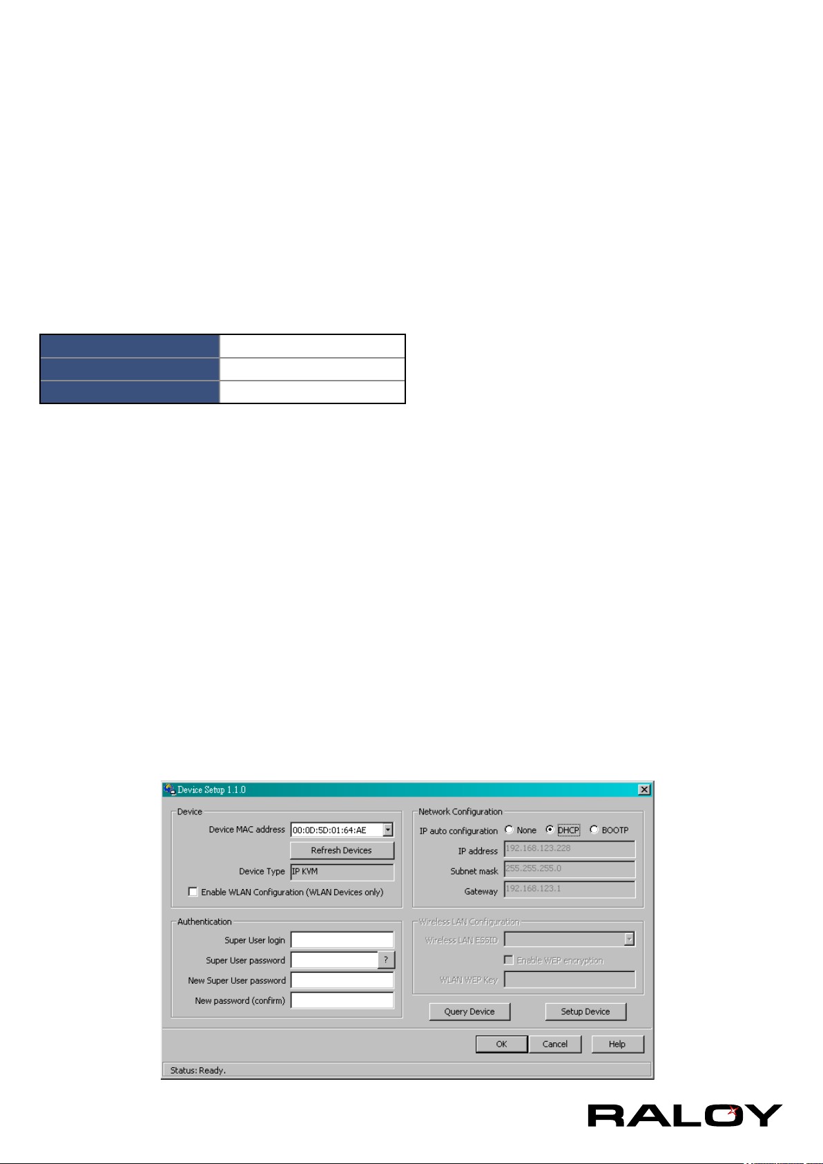
If you have installed the IP module on a network that enables DHCP, you can use the PSetup to nd out the
IP module’s IP.
1. Plug Ethernet cable to IP module. IP MODULE will get an IP via DHCP.
2. Using PSetup (run PSetup.exe) to look for IP MODULE.
a. Select MAC address which label on bottom of IP module
b. Click Query Device
Notes:
■ BOOTP, a static conguration protocol, uses a table that maps IP addresses to physical addresses.
■ DHCP, an extension to BOOTP that dynamically assigns conguration information. DHCP is
backward compatible with BOOTP.
1
Page 5
2. Setup Fixed IP
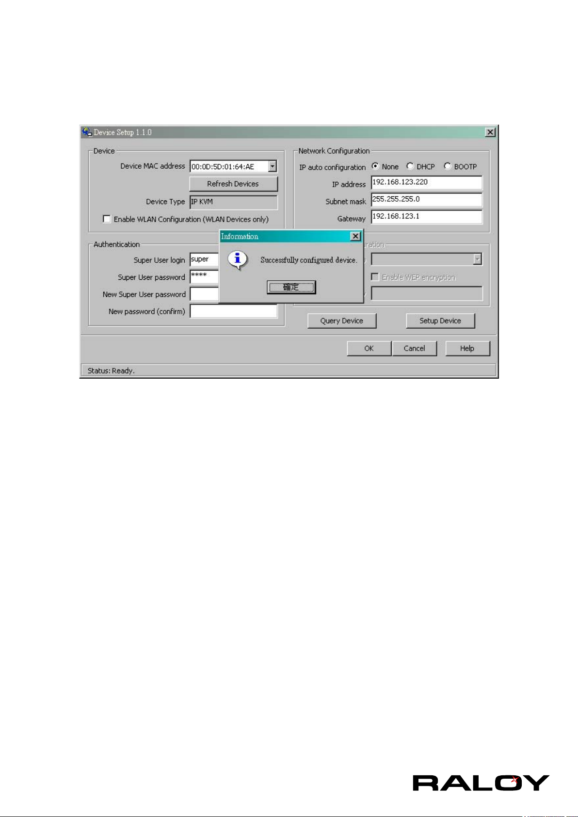
c. Setup “IP auto configuration” as “ None” ; setup IP address and Subnet mask
d. Enter Super user login and password for Authentication (default : super/pass)
e. Click Setup Device. If super login was authenticated, it’ll show “Successfully configured device”.
Otherwise it’ll show “Permission Denied”.
Authentication
To adjust the authentication settings, enter your login as a super user, and change your password.
Super user login
Enter the login name of the super user. The initial value is “super”. All characters
are in lower case.
Super user password
Enter the current password for the super user. This initial value is “pass”. All
characters are in lower case.
New super user password
Enter the new password for the super user.
New password (conrm)
Re-type the new password for the super user for conrmation.
To close the window and accept the changes, press the “OK” button; otherwise
press the “Cancel” button.
1-1.1 Setup Fixed IP
For using serial terminal, the IP module has a serial line interface (host side). This
connector is compliant with the RS-232 serial line standard. The serial line has to be
congured with the parameters given in the table below.
When conguring with a serial terminal, e.g., Hyper Terminal, reset the IP module and
immediately press the “ESC” key. You will see some device information, and a “=>”
2
Page 6

prompt. Enter “cong”, press “Enter” key and wait for a few seconds for the
conguration questions to appear.
Parameter Value
Bits/second 115200
Data bits 8
Parity No
Stop bits 1
Flow Control None
As you proceed, the following questions will appear on the screen. To accept the
default values shown in square brackets below, press “Enter” key.
IP auto conguration (none/dhcp/bootp):
IP [192.168.1.22]:
Net mask [255.255.255.0]:
Gateway (0.0.0.0 for none) [0.0.0.0]:
IP Auto-Conguration
With this option, you can specify whether the IP module should get its network settings from a DHCP
or BOOTP server. For DHCP, enter “dhcp”, and for BOOTP enter “bootp”. If you do not specify any of
these, the IP auto-conguration is disabled and subsequently you will be asked for the following network
settings.
IP Address
The IP address the IP module. This option is only available if IP auto-conguration is disabled.
Net Mask
The net mask of the connected IP subnet. This option is only available if IP auto-conguration is
disabled.
Gateway Address
The IP address of the default router for the connected IP subnet. If you do not have a default router,
enter 0.0.0.0. This option is only available if IP auto-conguration is disabled.
1-2 Keyboard, Mouse and Video Conguration
Between the IP module and the host, there are two interfaces available for transmitting keyboard and mouse
data: USB and PS/2. The correct operation of the remote mouse depends on several settings which will be
discussed in the following subsections.
1-2.1 IP Module Keyboard Settings
The IP module settings for the host’s keyboard type have to be corrected in order to make the remote
keyboard work properly. Check the settings in the IP module Web front-end. See section 3.5.2 for details.
1-2.2 Remote Mouse Settings
A common seen problem with KVM devices is the synchronization between the local and remote mouse
cursors. The IP module addresses this situation with an intelligent synchronization algorithm. There are two
mouse modes available on the IP module:
Auto Mouse Speed
The automatic mouse speed mode tries to detect the speed and acceleration settings of the host system
3
Page 7
automatically. See the section below for a more detailed explanation.
Fixed Mouse Speed
This mode just translates the mouse movements from the Remote Console in a way that one pixel move
will result in n-pixel moves on the remote system. This parameter n is adjustable with the scaling. Please
note that this works only when mouse acceleration is turned off on the remote system.
1-2.3 Automatic Mouse Speed and Mouse Synchronization
The automatic mouse speed mode performs the speed detection during mouse synchronization. Whenever
the local and remote mouse cursors move synchronously or not, there are two ways for re-synchronizing
local and remote mouse cursors:
Fast Sync
The fast synchronization is used to correct a temporary, but xed skew. Choose the option using the
Remote Console options menu or press the mouse synchronization hotkey sequence in case you
dened one.
Intelligent Sync
If the fast sync does not work or the mouse settings have been changed on the host system, use the
intelligent resynchronization. This method takes more time than the fast one and can be accessed with
the appropriate item in the Remote Console option menu. The intelligent synchronization requires a
correctly adjusted picture. Use the auto adjustment function to setup the picture, and make sure that
there are no windows at the top left corner of the remote desktop that are able to change the mouse
cursor shape from the normal state. The Sync mouse button on top of the Remote Console can behave
differently, depending on the current state of mouse synchronization. Usually pressing this button leads
to a fast sync, except in situations where the KVM port or the video mode changed recently.
Note: At rst start, if the local mouse pointer is not synchronized with the remote mouse pointer, press
the Auto Adjust Button once.
1-2.4 Host System Mouse Settings
The host’s operating system knows various settings from the mouse driver.
Warning
While the IP module works with accelerated mice and is able to synchronize the
local with the remote mouse pointer, there are the following limitations, which may
prevent this synchronization from working properly:
While the IP module works with accelerated mice and is able to synchronize the local with the remote
mouse pointer, there are the following limitations, which may prevent this synchronization from working
properly:
Special Mouse Driver
There are mouse drivers that inuence the synchronization process and lead to desynchronized mouse
pointers. If this happens, make sure you do not use a special vendor-specic mouse driver on your host
system.
Windows XP Mouse Settings
Windows XP knows a setting named “improve mouse acceleration”, which has to be deactivated.
Active Desktop
If the Active Desktop feature of Microsoft Windows is enabled do not use a plain background. Instead,
use some kind of wallpaper. As an alternative, you could also disable the Active Desktop completely.
4
Page 8

Navigate your mouse pointer into the upper left corner of the applet screen and move it slightly forth and
back. Thus the mouse will be resynchronized. If re-synchronizing fails, disable the mouse acceleration
and repeat the procedure.
1-2.5 Single and Double Mouse Mode
The information above applies to the Double Mouse Mode, where remote and local mouse pointers are
visible and need to be synchronized. The IP module also features another mode, the Single Mouse Mode,
where only the remote mouse pointer is visible. Activate this mode in the open Remote Console and click
into the window area. The local mouse pointer will be hidden and the remote one can be controlled directly.
To leave this mode, it is necessary to dene a mouse hotkey in the Remote Console Settings Panel. Press
this key to free the captured local mouse pointer.
1-2.6 Recommended Mouse Settings
For the different operating systems we can give the following advice:
MS Windows 2000/2003 (Professional and Server) and XP (all versions)
In general, we recommend the usage of a mouse via USB. Choose USB without Mouse Sync. For a
PS/2 mouse choose Auto Mouse Speed. For XP disable the option “enhance pointer precision” in the
Control Panel.
SUN Solaris
Adjust the mouse settings either via xset m 1 or use the CDE Control Panel to set the mouse to “1:1, no
acceleration”. As an alternative you may also use the Single Mouse Mode.
MAC OS X
We recommend using the Single Mouse Mode.
1-2.7 Video Modes
The IP module recognizes a limited number of common video modes. When running X11 on the host
system, please do not use any custom mode lines with special video modes. If you do, the IP module may
not be able to detect them. We recommend using any of the standard VESA video modes, instead.
5
Page 9

2 Usage
2-1 Prerequisites
The IP module features an embedded operating system and applications offering a variety of standardized
interfaces. This chapter will describe both these interfaces, and the way to use them in a more detailed
manner. The interfaces are accessed using the TCP/IP protocol family, thus they can be accessed using the
LAN port of the device.
The following interfaces are supported:
HTTP/HTTPS
Full access is provided by the embedded web server. The IP module environment can be entirely managed
using a standard web browser. You can access the IP module using the insecure HTTP protocol, or using
the encrypted HTTPS protocol. Whenever possible, use HTTPS.
Telnet
A standard Telnet client can be used to access an arbitrary device connected to the IP module’s serial
port via a terminal mode. The primary interface of the IP module is the HTTP interface. This is covered
extensively in this chapter. Other interfaces are addressed in subtopics.
In order to use the Remote Console window of your managed host system, the browser has to come with a
Java Runtime Environment version 1.4.2 or above. If the browser has no Java support (such as on a small
handheld device), you are still able to maintain your IP module using the administration forms displayed by the
browser itself.
Note: We recommend installing a Sun JVM 1.5.0.4.
For an insecure connection to the IP module, we can recommend the following browsers:
■ Microsoft Internet Explorer version 6.0 or higher on Windows 2000 and Windows XP
■ Netscape Navigator 7.0 or Mozilla 1.6 on Windows 2000, Windows XP, Unix, Linux and UNIX-like Operating
Systems
In order to access the remote host system using a securely encrypted connection, you need a browser that
supports the HTTPS protocol. Strong security is only assured by using a key length of 128 Bit. Some of the old
browsers do not have a strong 128 Bit encryption algorithm.
Using the Internet Explorer, open the menu entry “?” and “Info” to read about the key length that is currently
activated. The dialog box contains a link that leads you to information on how to upgrade your browser to a
state of the art encryption scheme. The image below shows the dialog box presented by the Internet Explorer
6.0.
Newer web browsers generally support strong encryption on default.
6
Page 10

2-2 Login into the IP Module and Logout
2-2.1 Login into the IP Module
Launch your web browser. Direct it to the address of your IP module, which you congured during the
installation process. The address used might be an IP address or a domain name, in the case where you
have given your IP module a symbolic name in the DNS. For instance, type the following in the URL eld of
your browser when establishing an unsecured connection:
http://<IP address of IP module>
When using a secure connection, type in:
https://<IP address of IP module>
This will lead you to the IP module login page as shown below.
The IP module has a built-in super user that has all permissions to administrate your IP module:
Warning
■ The user “super” is not allowed to login via the serial interface of the IP module
■ Please make sure to change the super user password immediately after you
have installed and accessed your IP module for the rst time. Unchanging of
the password for the super user is a severe security risk and might result in
unauthorized access to the IP module and to the host system including all possible
consequences!
■ Your web browser has to accept cookies, or else login is not possible.
Navigation
Having logged into the IP module successfully, the main page of the IP module appears. This page consists
of three parts; each of them contains specic information. The buttons on the upper side allow you to
navigate within the front end. Within the right frame, task-specic information is displayed that depends on
the section you have chosen before.
7
Page 11
Return to the main page of the IP module.
Open the IP module remote console.
Exit from the IP module front end.
Warning
If there is no activity for 30 minutes, the IP module will log you out, automatically. A
click on one of the links will bring you back to the login screen.
2-2.2 Logout from the IP Module
This link logs out the current user and presents a new login screen. Please note that an automatic logout
will be performed if there is no activity for 30 minutes.
2-3 The Remote Console
The Remote Console is the redirected screen, keyboard and mouse of the remote host system that IP module
controls.
The Remote Console window is a Java Applet that tries to establish its own TCP connection to the IP
module. The protocol that is run over this connection is neither HTTP or HTTPS, but RFB (Remote Frame
Buffer Protocol). As default, RFB tries to establish a connection to TCP port number 443. Your local network
environment has to allow this connection to be made, i.e. your rewall and, in case you have a private internal
network, your NAT (Network Address Translation) settings have to be congured accordingly.
In case the IP module is connected to your local network environment and your connection to the Internet is
available using a proxy server only without NAT being congured, the Remote Console is very unlikely to be
able to establish the desired connection. This is because today’s web proxies are not capable of relaying the
RFB protocol.
In case of problems, please consult your network administrator in order to provide an appropriate networking
environment.
8
Page 12
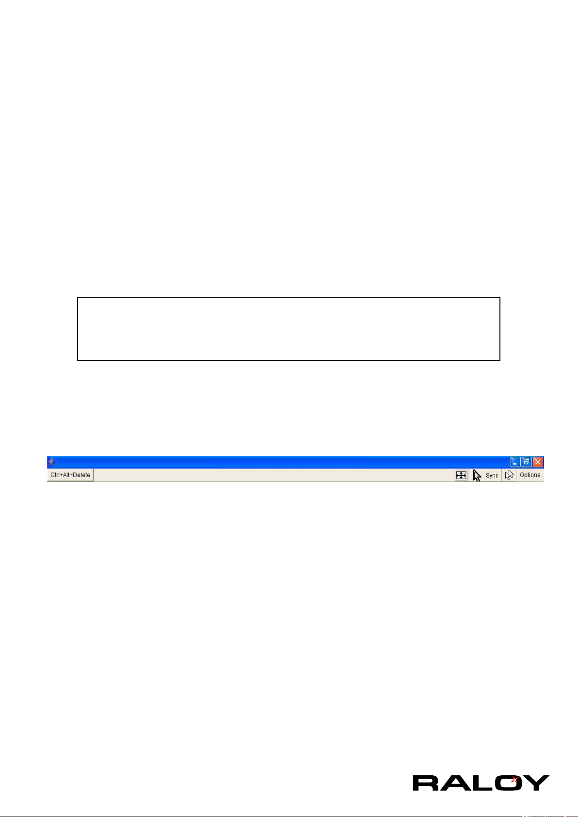
2-4 Main Window
Starting the Remote Console opens an additional window. It displays the screen content of your host system.
The Remote Console will behave exactly in the same way as if you were sitting locally in front of the screen
of your remote system. That means keyboard and mouse can be used in the usual way. However, be aware
of the fact that the remote system will react to keyboard and mouse actions with a slight delay. The delay
depends on the bandwidth of the link to which you use to connect to the IP module.
With respect to the keyboard, the very exact remote representation might lead to some confusion as your
local keyboard changes its keyboard layout according to the remote host system. If you use a German
administration system, and your host system uses a US English keyboard layout, for instance, special keys on
the German keyboard will not work as expected. Instead, the keys will result in their US English counterpart.
You can circumvent such problems by adjusting the keyboard of your remote system to the same mapping as
your local one.
The Remote Console window always tries to show the remote screen with its optimal size. That means it will
adapt its size to the size of the remote screen initially and after the screen resolution of the remote screen has
been changed. However, you can always resize the Remote Console window in your local window system as
usual.
Warning
In difference to the remote host system, the Remote Console window on your local
window systemis just one window among others. In order to make keyboard and
mouse work, your Remote Console window must have the local input focus.
2-4.1 Remote Console Control Bar
The upper part of the Remote Console window contains a control bar. Using its elements you can see the
state of the Remote Console and adjust the local Remote Console settings. A description for each control
follows.
Ctrl+Alt+Delete
Special button key to send the “Control Alt Delete” key combination to the remote system (see also
section 3.4.1 for dening new button keys).
Auto Adjust button
If the video display is of bad quality or distorted in some way, press this button and wait a few seconds
while the IP module tries to detect the video mode of VGA port to the controlled host and adjust itself for
the best possible video quality.
Sync mouse
Activates the mouse synchronization process. Choose this option in order to synchronize the local with
the remote mouse cursor. This is especially necessary when using accelerated mouse settings on the
host system. In general, there is no need to change mouse settings on the host.
Single/Double mouse mode
Switches between the Single Mouse Mode (where only the remote mouse pointer is visible) and the
Double Mouse Mode (where remote and local mouse pointers are visible and need to be synchronized).
Single mouse mode is only available if using SUN JVM 1.4.2 or higher.
Options
To open the Options menu, click on the button “Options”.
9
Page 13
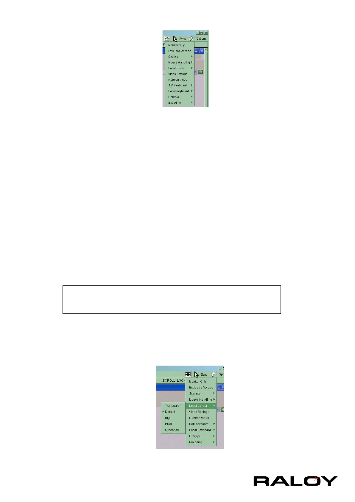
A short description of the options follows.
■ Monitor Only
Toggles the Monitor only lter on or off. If the lter is switched on no remote console interaction is
possible, and monitoring is possible.
■ Exclusive Access
If a user has the appropriate permission, he or she can force the Remote Consoles of all other users
to close. No one can open the Remote Console at the same time again until this user disables the
exclusive access, or logs off. A change in the access mode is also visible in the status line.
■ Mouse Handling
The submenu for mouse handling offers two options for synchronizing the local and the remote mouse
cursors.
Fast Sync
The fast synchronization is used to correct a temporary, but xed skew.
Intelligent Sync
Use this option if the fast sync does not work or the mouse settings have been changed on the
host system.
Warning
This method takes more time than the fast one and requires a correctly
adjusted picture. Use the auto adjustment function to setup the picture.
■ Local Cursor
Offers a list of different cursor shapes to choose from for the local mouse pointer. The selected shape
will be saved for the current user and activated the next time this user opens the Remote Console.
The number of available shapes depends on the Java Virtual Machine; a version of 1.4.2 or above
offers the full list.
10
Page 14
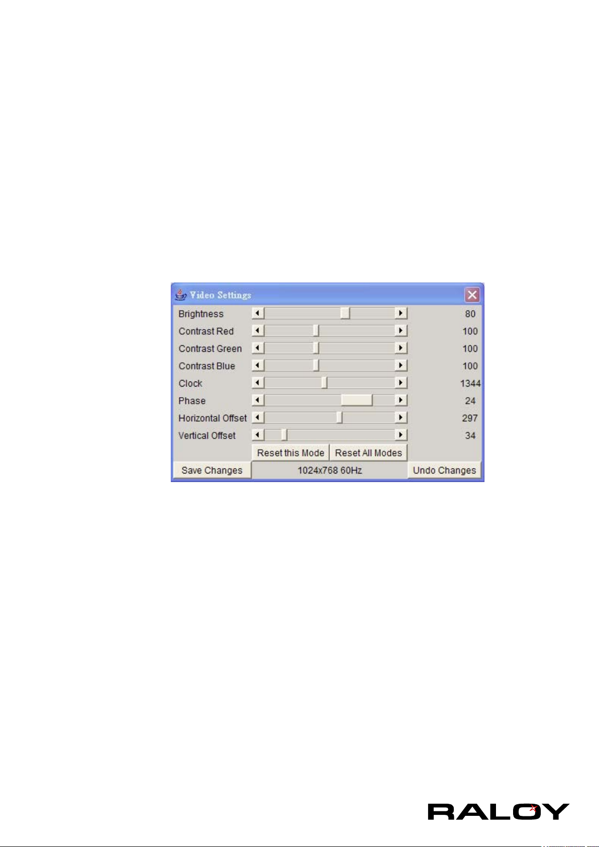
■ Video Settings
Opens a panel for changing the IP module video settings. IP module features two different dialogs,
which for adjusting the video settings.
Video Settings through the HTML-Frontend
To enable local video port, select this option. This option decides if the local video output of IP
module is active and passing through the incoming signal from the host system.
The option Noise Filter denes how IP module reacts to small changes in the video input signal.
Turning on the noise lter can help reduce video ickering that is often caused by distortions, as
well as lowering unnecessary bandwidth consumption. A large lter setting needs less network
trafc and leads to a faster video display, but small changes in some display regions may not be
recognized immediately. A small lter displays all changes instantly but may lead to a constant
amount of network trafc even if display content is not really changing (depending on the quality of
the video input signal). All in all the default setting should be suitable for most situations.
Video Settings through the remote console:
Brightness
Controls the brightness of the picture
Contrast
Controls the contrast of the picture
Clock
Denes the horizontal frequency for a video line and depends on the video mode. Different
video card types may require different values here. The default settings in conjuction with the
auto adjustment procedure should be adequate for all common congurations. If the picture
quality is still bad after auto adjustment you may try to change this setting together with the
sampling phase to achieve a better quality.
Phase
Denes the phase for video sampling, used to control the display quality together with the
setting for sampling clock.
Horizontal Position
Use the left and right buttons to move the picture in horizontal direction while this option is
selected.
11
Page 15
Vertical Position
Use the left and right buttons to move the picture in vertical direction while this option is
selected.
Reset this Mode
Reset mode specic settings (Clock , Phase and Position) to the factory-made defaults.
Reset all Modes
Reset all settings to the factory-made defaults.
Save changes
Save changes permanently
Undo Changes
Restore last settings
■ Refresh Video
Click to run this menu item for retrieving the whole video again from the controlled host and displayed
on Remote Console. In normal situation, only changed parts of video will be packed and sent from IP
module, for saving network bandwidth. This function is mainly used for troubleshooting purpose where
some old video fragments are displayed as not updated in time for some reason; for example, noise
lter for VGA is setting too large.
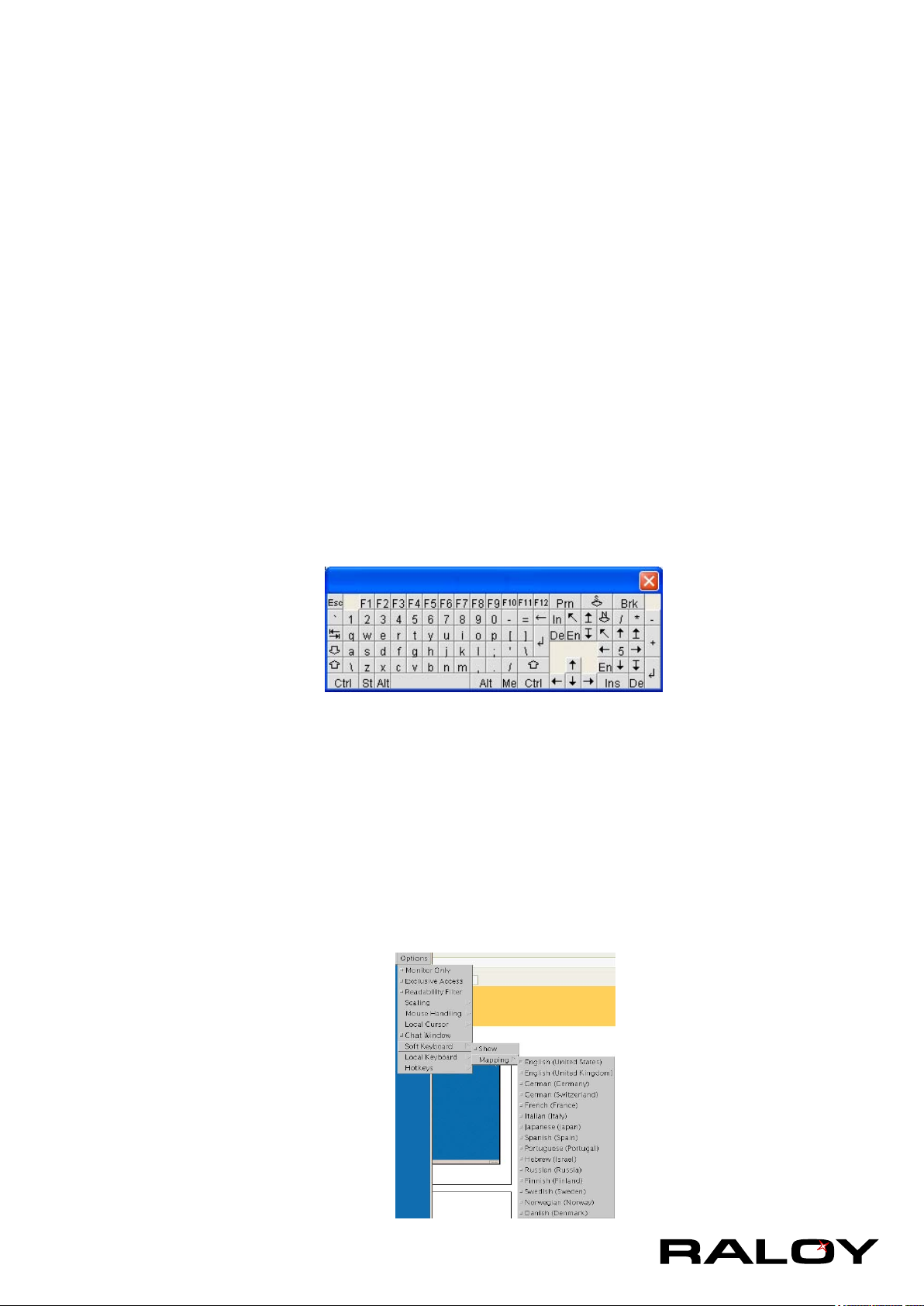
■ Soft Keyboard
Opens up the Menu for the Soft-Keyboard.
■ Show
Pops up the Soft-Keyboard. The Soft-Keyboard is necessary in case your host
system runs a completely different language and country mapping than your
administration machine.
■ Mapping
Used for choosing the specic language and country mapping of the
Soft-Keyboard.
12
Page 16
■ Local Keyboard
Used to change the language mapping of your browser machine running the Remote Console
Applet. Normally, the applet determines the correct value automatically. However, depending on
your particular JVM and your browser settings this is not always possible. A typical example is a
German localized system that uses an US-English keyboard mapping. In this case you have to
change the Local Keyboard setting to the right language, manually.
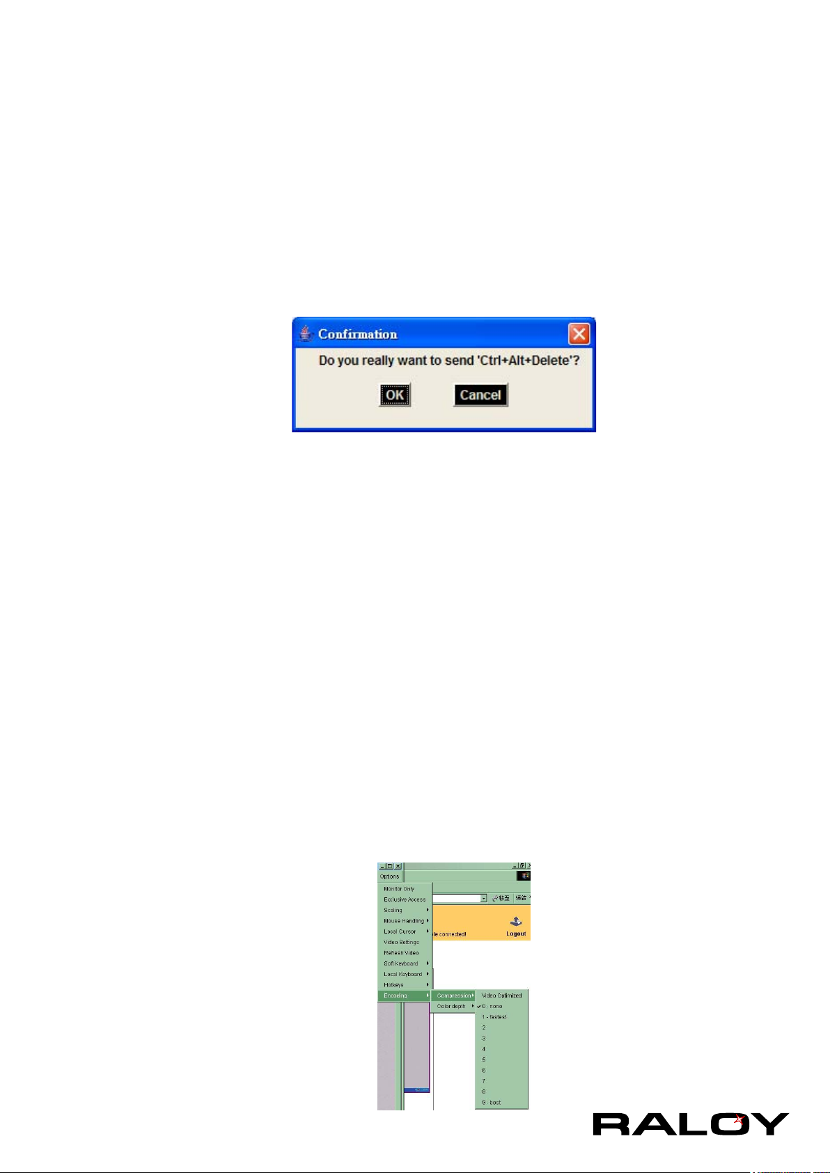
■ Hotkeys
Opens a list of hotkeys dened before. Choose one entry, the command will be sent to the host
system.
A conrmation dialog can be added that will be displayed before sending the selected command to
the remote host. Select “OK” to execute the command on the remote host.
■ Encoding
These options are used to adjust the encoding level in terms of compression and color depth. They
are only available unless “Transmission Encoding” is determined automatically (see the Section called
Transmission Encoding in Chapter 3).
Compression Level:
You may select a value between 1 and 9 for the desired compression level with level 1 enabling
the fastest compression and level 9 the best compression. The most suitable compression level
should always be seen as a compromise between the network bandwidth that is available, on your
video picture to be transferred, and on the number of changes between two single video pictures.
We recommend to use a higher compression level if the network bandwidth is low. The higher the
compression level the more time is needed to pack and unpack the video data on either side of the
connection. The compression quality depends on the video picture itself, e.g. the number of the
colors or the diversity of pixels. The lower the compression quality, the more data have to be sent
and the longer it may take to transfer the whole video picture.
If level 0 is chosen the video compression is disabled, completely.
The option “Video Optimized” has its advantages if transferring high-quality motion pictures. In this
case the video compression is disabled, completely and all video data is transferred via network as
full-quality video snippets. Therefore, a high amount of bandwidth is required to ensure the quality
of the video picture.
13
Page 17
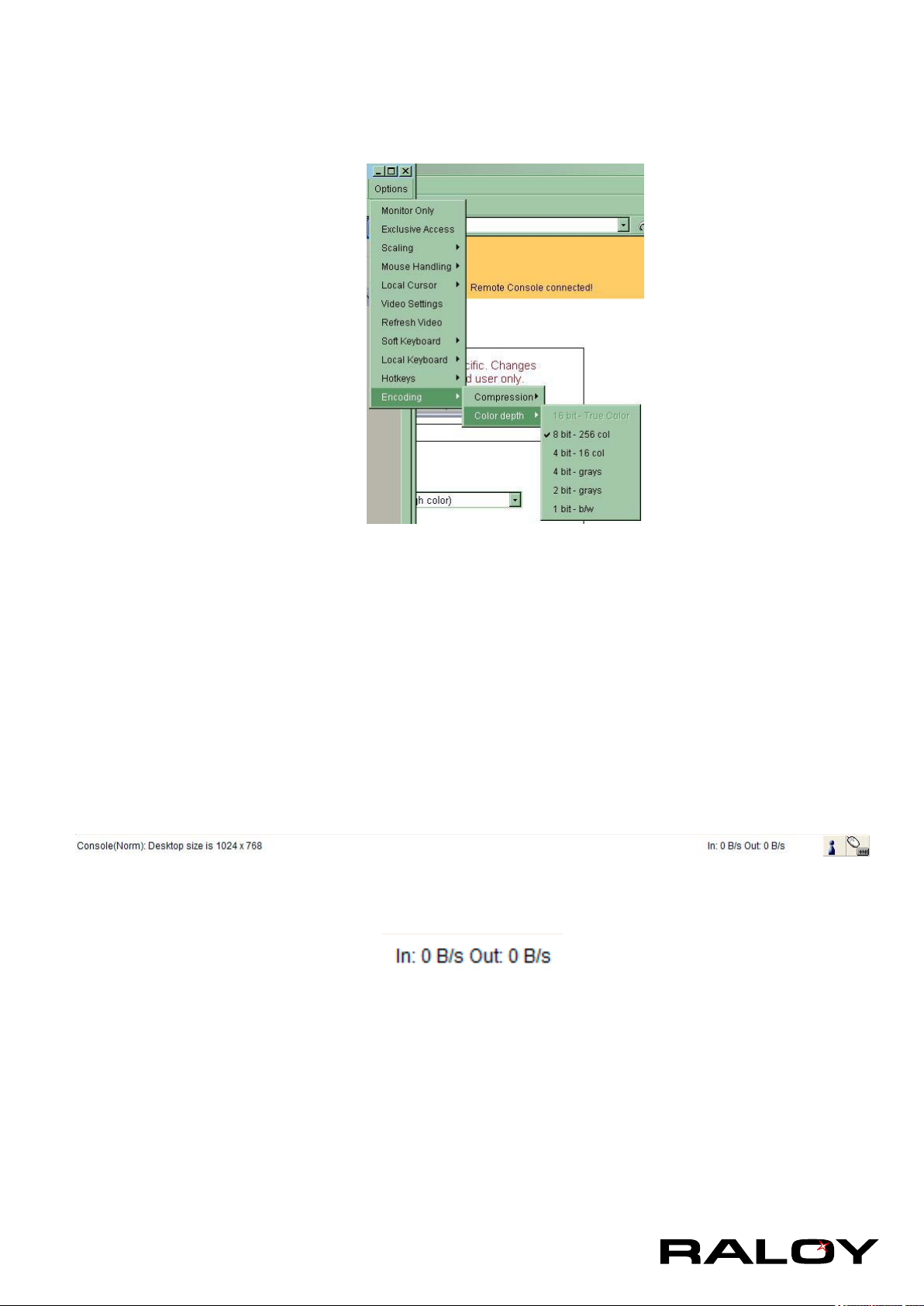
Color Depth
Set the desired color depth. You may select between 8 or 16 bit for Video Optimized/compression
level 0, or between 1 and 8 bit for compression level 1 to 9. The higher the color depth, the more
video information has to be captured and to be transferred.
Note: If displaying motion pictures on a connection with low speed you may achieve an
improvement regarding the video transfer rate by lowering the color depth and disabling the option
“Video Optimized”. As a general result, the data rate is reduced (less bits per color). Furthermore,
the OPMA module will not have to do any video compression. In total, this will lead to less transfer
time of the motion picture.
2-4.2 Remote Console Status Line
Status line
Shows both console and the connection state. The size of the remote screen is displayed. The image below
was taken from a Remote Console with a resolution of 800x600 pixels. The value in brackets describes the
connection to the Remote Console. “Norm” means a standard connection without encryption, “SSL” means
a secure connection.
Furthermore, both the incoming (“In:”) and the outgoing (“Out:”) network trafc are visible (in kb/s). If
compressed encoding is enabled, a value in brackets displays the compressed transfer rate.
For more information about Monitor Only and Exclusive Access settings, see related
sections
14
Page 18
3 Menu Options
3-1 Remote Control
3-1.1 KVM Console
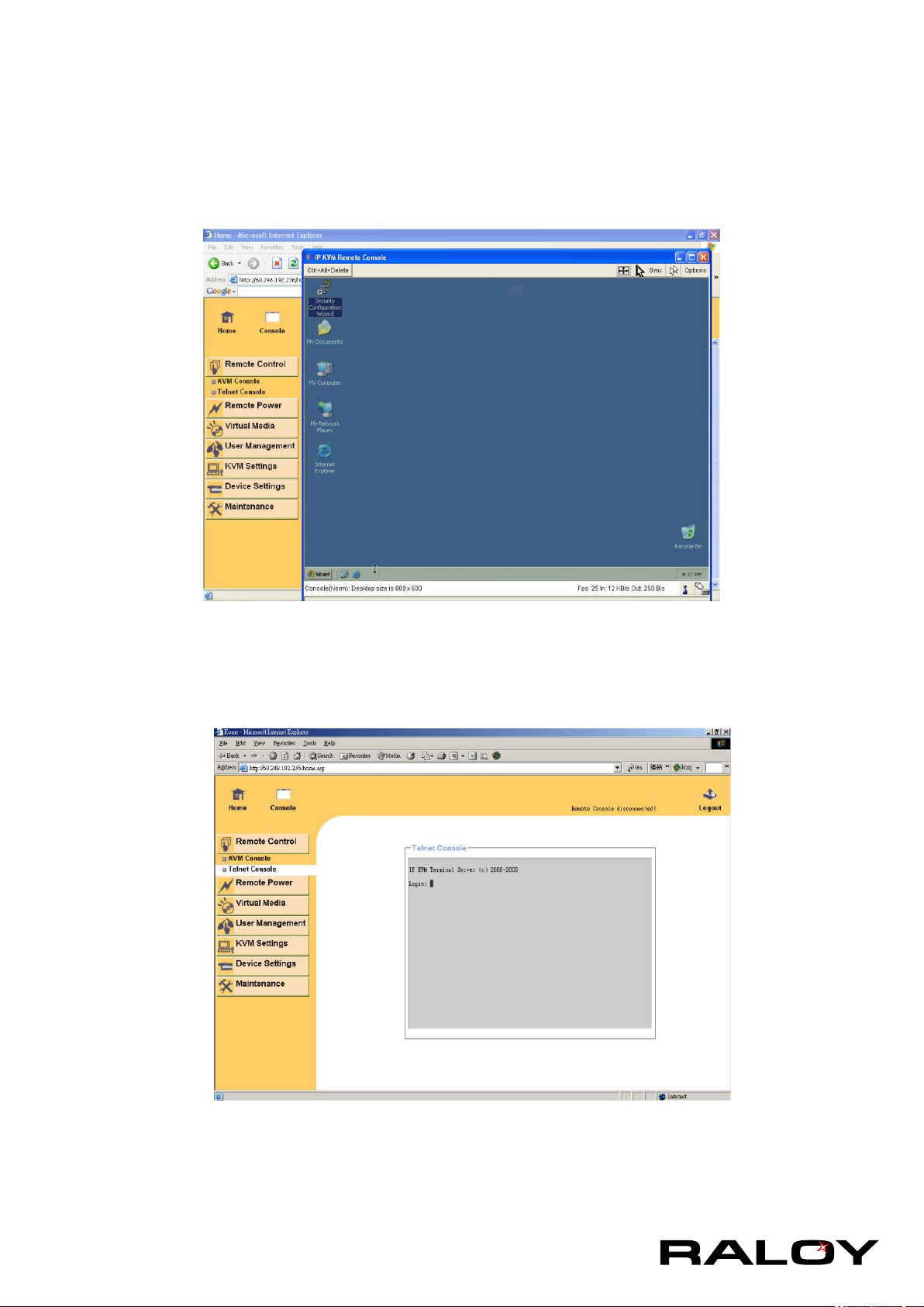
To open the KVM console, either click on the menu entry on the left, or on the console
picture on the right. To refresh the picture, click on the button “Refresh”.
3-1.2 Telnet Console
The IP module rmware features a Telnet server that enables a user to connect via a standard Telnet client.
In case the Telnet program is using a VT 100, VT 102 or VT 220 terminal or an according emulation, it is
even possible to perform a console redirection as long as the IP module host machine is using a text mode
screen resolution.
15
Page 19
Connecting to the IP module is done as usual and as required by the Telnet client, for instance in a UNIX
shell:
telnet 192.168.1.22
Replace the IP address by the one that is actually assigned to the IP module. This will prompt for username
and password in order to log into the device. The credentials that need to be entered for authentication are
identical to those of the web interface. That means, the user management of the Telnet interface is entirely
controlled with the according functions of the web interface.
Once you have successfully logged into the IP module a command line will be presented and you can enter
according management commands.
In general, the Telnet interface supports two operation modes: the command line mode and the terminal
mode. The command line mode is used to control or display some parameters. In terminal mode the pass-
through access to serial port 1 is activated (if the serial settings were congured accordingly). All inputs are
redirected to the device on serial port 1 and its answers are displayed on the Telnet interface.
The following list shows the according command mode command syntax and their usage.
help
Displays the list of possible commands
cls
Clears the screen
quit
Exits the current session and disconnects from the client
version
Displays the release information
terminal
Starts the terminal passthrough mode for serial port 1. The key sequence
esc exit
switches back to the command mode.
3-2 User Management
3-2.1 Change Password
16
Page 20
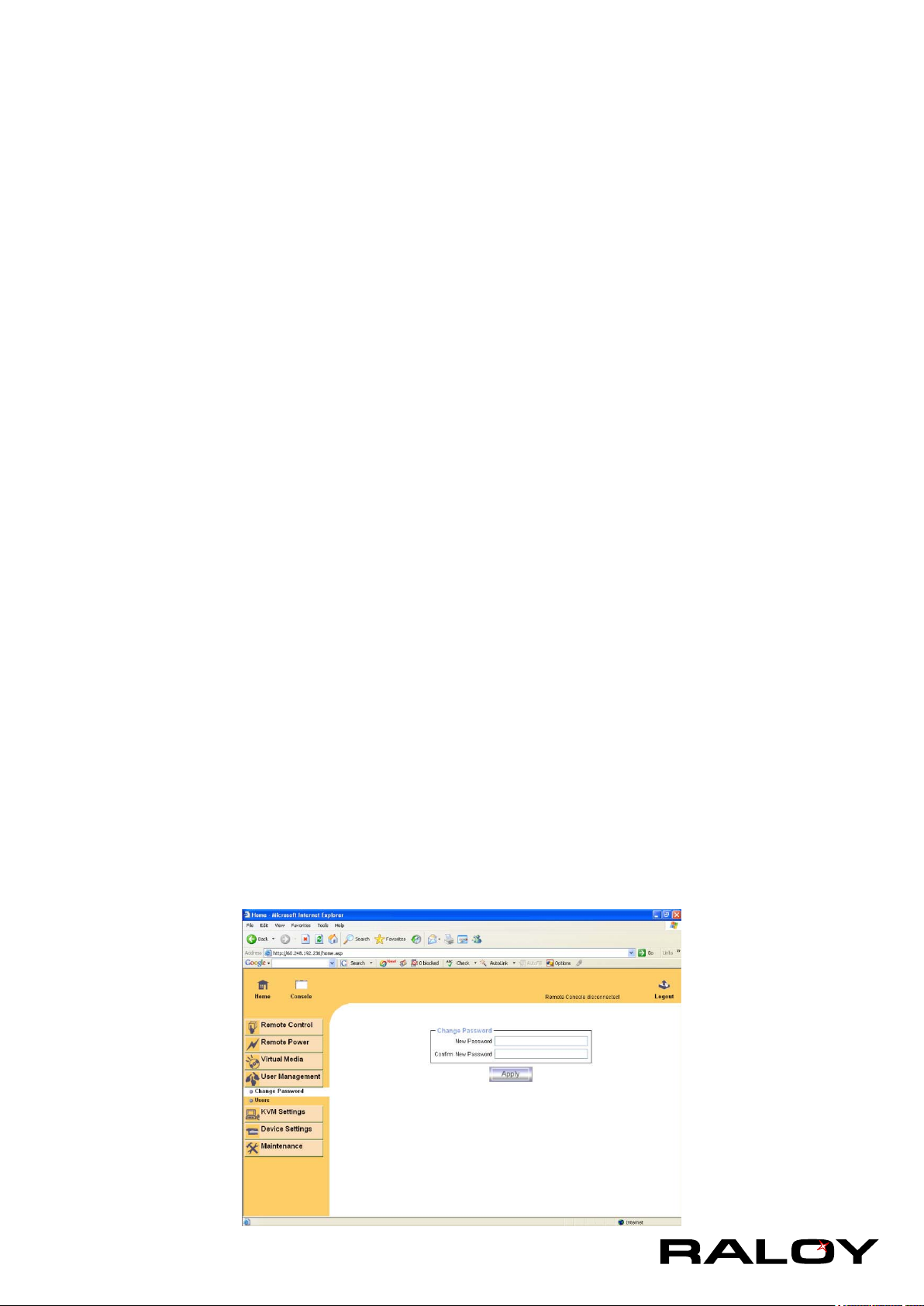
To change your password, enter the new password in the upper entry eld. Retype the password in the eld
below. Click “Apply” to submit your changes.
3-2.2 Users and Groups
The IP module comes with 1 pre-congured user account that has xed permissions. The account “super”
has all possible rights to congure the device and to use all functions IP module offers.
Upon delivery, the account “super” has the password “pass”. Make sure to change password immediately
after you have installed and on initial access of your IP module.
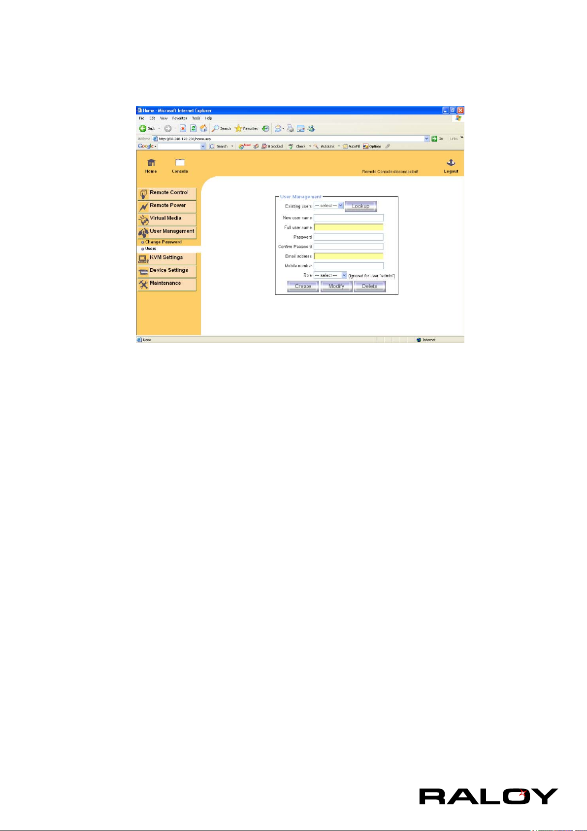
Existing users
Select an existing user for modication. Once a user has been selected, click the lookup button to see
the user information.
New User Name
The new user name for the selected account.
Password
The password for the login name. It must be at least three characters long.
Conrm password
Conrmation of the password above.
Email address
This is optional.
Mobile number
This information may be optionally provided.
Role
Each user can be a member of a group (named a “role” ) - either an administrator, or an regular user.
Choose the desired role from the selection box.
To create an user press the button “Create”. The button “Modify” changes the displayed user settings. To
delete an user press the button “Delete”.
Note:The IP MODULE is equipped with an host-independent processor and memory unit which both have a
17
Page 21
limitation in terms of the processing instructions and memory space. To guarantee an acceptable response
time we recommend not to exceed the number of 15 users connected to the IP MODULE at the same time.
The memory space that is available onto the IP MODULE mainly depends on the conguration and the
usage of the IP MODULE (log le entries etc.). That’s why we recommend not to store more than 150 user
proles.
3-3 KVM Settings
3-3.1 User Console
The following settings are user specic. That means, the super user can customize these settings for every
users separately. Changing the settings for one user does not affect the settings for the other users.
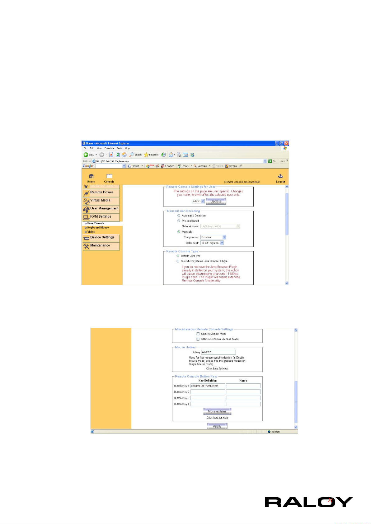
User select box
This selection box displays the user ID for which the values are shown and for
which the changes will take effect. You may change the settings of other users if
you have the required privileges.
Remote Console Type
Species, which Remote Console Viewer to use.
Default Java-VM
Uses the default Java Virtual Machine of your Browser. This may be the Microsoft JVM for the Internet
Explorer, or the Sun JVM if it is congured this way. Use of the Sun JVM may also be forced (see
18
Page 22

below).
Sun Microsystems Java Browser Plugin
Instructs the web browser of your administration system to use the JVM of Sun Microsystems. The
JVM in the browser is used to run the code for the Remote Console window, which is actually a Java
Applet. If you check this box for the rst time on your administration system and the appropriate Java
plug-in is not already installed on your system, it will be downloaded and installed automatically.
However, in order to make the installation possible, you still need to answer the according dialogs with
“yes” . The download volume is around 11 Mbytes. The advantage of downloading Sun’s JVM lays in
providing a stable and identical Java Virtual Machine across different platforms. The Remote Console
software is optimized for this JVM versions and offers wider range of functionality when run in SUN’s
JVM. Please make sure that you are installing Sun JVM 1.4.2 or above to your client system.
Miscellaneous Remote Console Settings
■ Start in Monitor Mode
Sets the initial value for the monitor mode. By default the monitor mode is off. In case you switch it
on, the Remote Console window will be started in a read only mode.
■ Start in Exclusive Access Mode
Enables the exclusive access mode immediately at Remote Console startup. This forces the
Remote Consoles of all other users to close. No one can open the Remote Console at the same
time again until this user disables the exclusive access or logs off.
Mouse Hotkey
Allows to specify a hotkey combination which starts either the mouse synchronization process if
pressed in the Remote Console, or is used to leave the single mouse mode.
Remote Console Button Keys
Button Keys allow simulating keystrokes on the remote system that cannot be generated locally.
The reason for this might be a missing key or the fact, that the local operating system of the Remote
Console is unconditionally catching this keystroke already. Typical examples are “Control+Alt+Delete”
on Windows and DOS, what is always caught, or “Control+Backspace” on Unix or Unix-like OS for
terminating the X-Server. The syntax to dene a new Button Key is as follows:
[conrm] <keycode>[+|-[*]<keycode>]*
“conrm” requests conrmation by a dialog box before the key strokes will be sent to the remote host.
“keycode” is the key to be sent. Multiple key codes can be concatenated with a plus, or a minus sign.
The plus sign builds key combinations, all keys will be pressed until a minus sign or the end of the
combination is encountered. In this case all pressed keys should be released in reversed sequence. The
minus sign builds single, separate key presses and releases. The star inserts a pause with duration of
100 milliseconds.
19
Page 23
3-3.2 Keyboard / Mouse
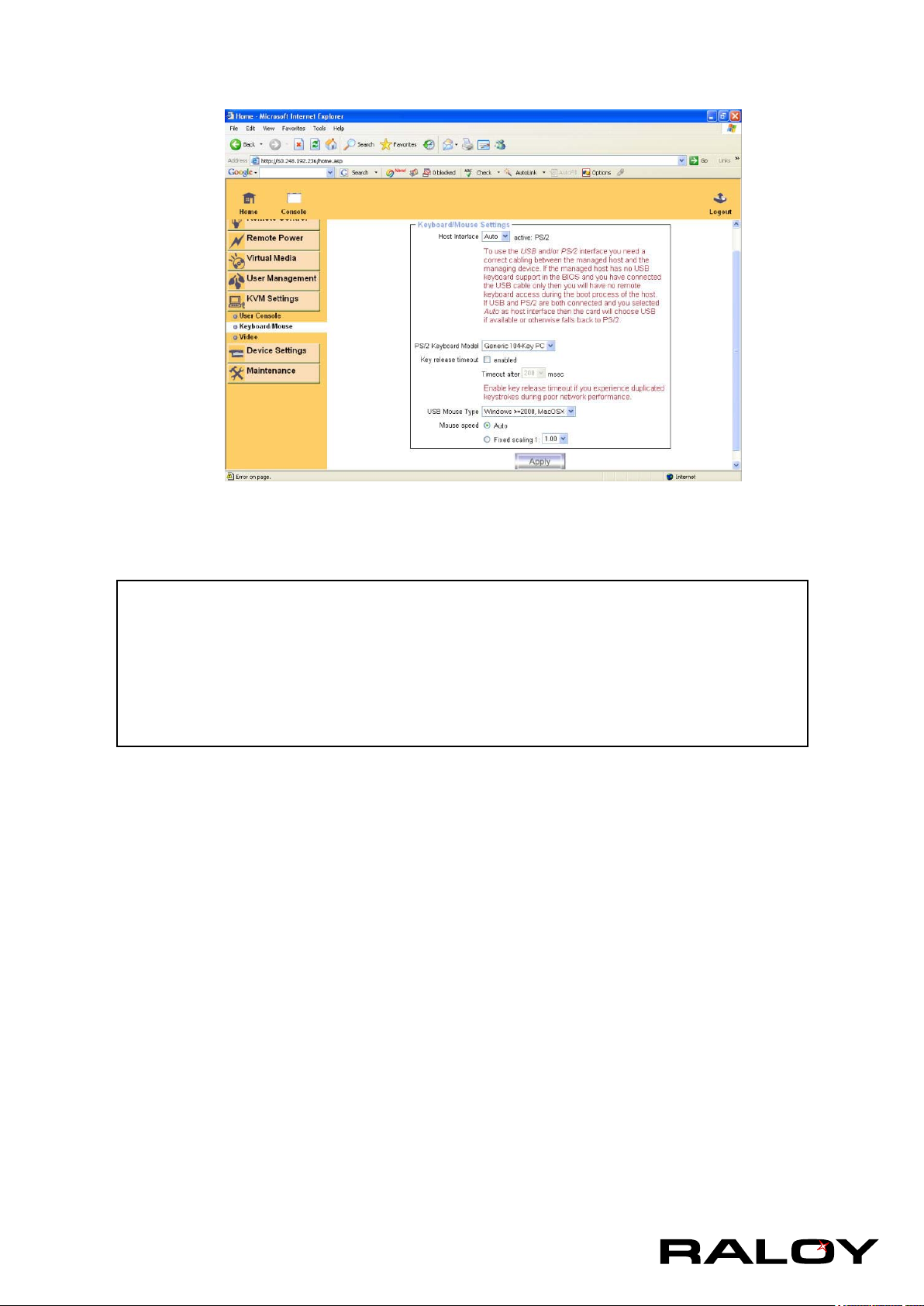
Host Interface
Enables a certain interface the mouse is connected to. You can choose between “Auto” for automatic
detection, “USB” for an USB mouse, and “PS/2” for a PS/2 mouse.
Warning
To use the USB and/or PS/2 interface you need a correct cabling between the
managed host and the managing device. If the managed host has no USB keyboard
support in the BIOS and you have connected the USB cable only then you will have no
remote keyboard access during the boot process of the host. If USB and PS/2 are both
connected and you selected “Auto” as host interface, then the card will select “USB” if
available or otherwise falls back to “PS/2”.
To get USB remote keyboard access during the boot process of the host, the following conditions must
be fullled:
■ The host BIOS must have USB keyboard support
■ The USB cable must be connected or must be selected in the Host interface option
PS/2 Keyboard Model
Enables a certain keyboard layout. You can choose between “Generic 101-Key PC” for a standard
keyboard layout, “Generic 104-Key PC” for a standard keyboard layout extendend by three additional
windows keys, “Generic 106-Key PC” for a japanese keyboard, and “Apple Macintosh” for the Apple
Macintosh.
Keyboard timeout
Recommanded as “enable” for keyboard timeout when host is UNIX or UNIX-like OS.
USB Mouse Type
Enables USB mouse type. Choose between “Windows >= 2000 , MacOSX” for MS Windows 2000 or
Windows XP, Mac OSX or “Other Operating Systems” for MS Windows NT, Unix or Unix-like OS, or
OS X. In “Windows >= 2000 , MacOSX” mode the remote mouse is always synchronized with the local
mouse.
20
Page 24
Mouse Speed
■ Auto mouse speed
Use this option if the mouse settings on host use an additional acceleration
setting. The IP module tries to detect the acceleration and speed of the mouse
during the mouse sync process.
■ Fixed mouse speed
Use a direct translation of mouse movements between the local and the remote
pointer.
You may also set a xed scaling which determines the pixel-amount of the
remote mouse pointer movement when the local mouse pointer is moved by one
pixel. This option is used to manually control the remote mouse speed and only
works when the mouse settings on the host are linear. This means mouse
acceleration of OS should be disabled, and the intelligent mouse synchronization
of IP module is not functioning under this setting.
To set the options, click on the button “Apply”.
3-3.3 Video
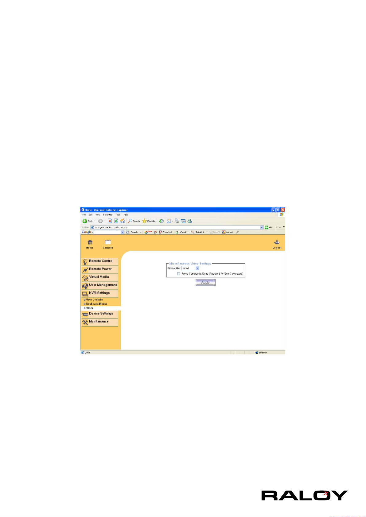
Miscellaneous Video Settings
■ Noise lter
This option denes how the IP module reacts to small changes in the video input signal. Turning on
the noise lter can help reduce video ickering that is often caused by distortions, as well as lowering
unnecessary bandwidth consumption. A large lter setting needs less network trafc and leads to a
faster video display, but small changes in some display regions may not be recognized immediately. A
small lter displays all changes instantly but may lead to a constant amount of network trafc even if the
display content is not really changing (depending on the quality of the video input signal). All in all the
default setting should be suitable for most situations.
■ Force Composite Sync (Required for Sun Computers)
21
Page 25
When connecting the device directly to legacy Sun computer (with composite sync as the video output,
it may be possible that IP MODULE don’t recognize the composite sync automatically. To support signal
transmission from a Sun machine, enable this option. If not enabled the picture of the remote console will
not be visible. To set the options, click on the button “Apply”
3-4 Device Settings
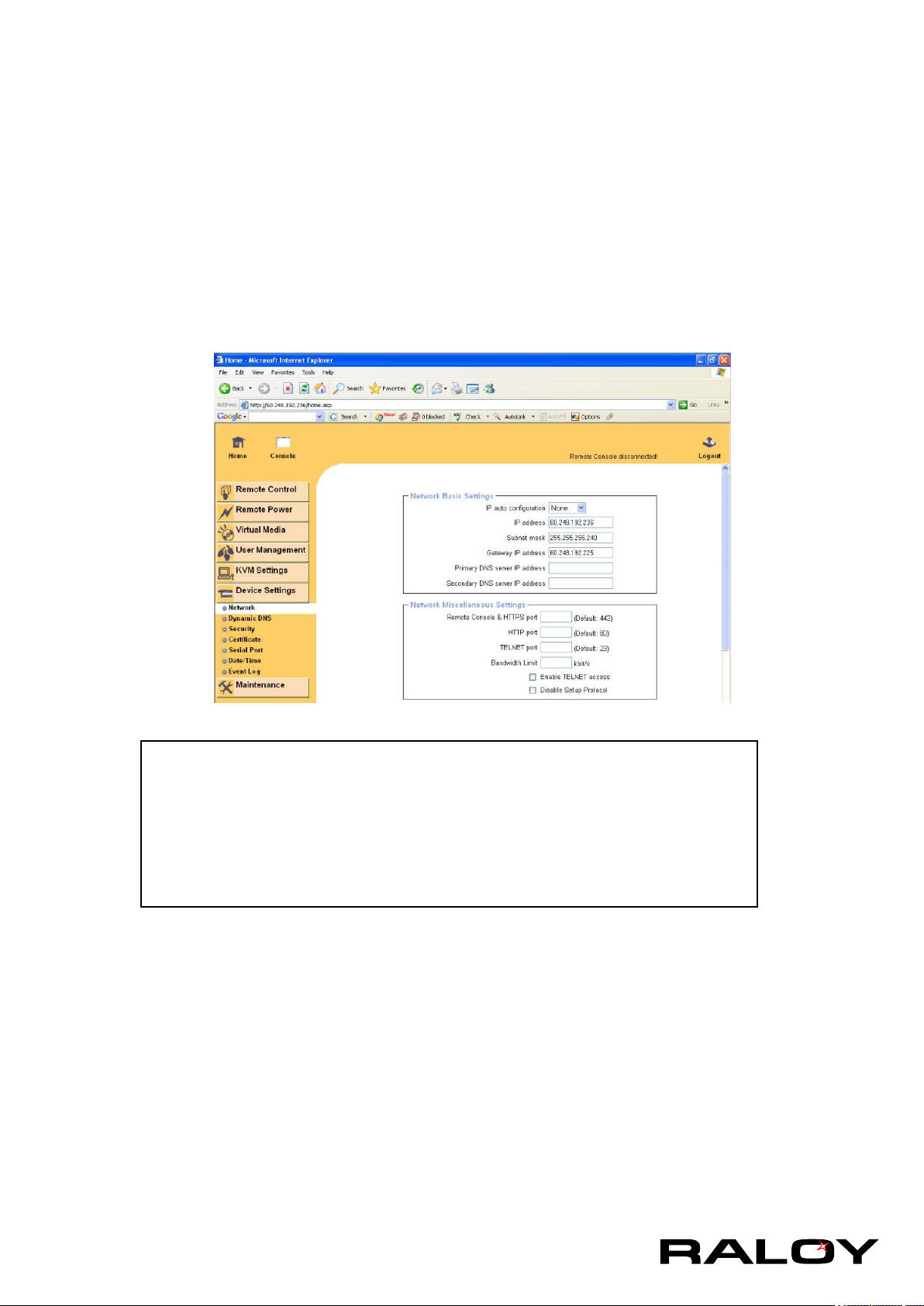
3-4.1 Network
The Network Settings panel as shown below allows changing network related parameters. Each parameter
will be explained below. Once applied the new network settings will immediately come into effect.
Warning
The initial IP conguration is usually done directly at the host system using the
special procedure.
Changing the network settings of the IP module might result in losing
connection to it. In case you change the settings remotely make sure that all
the values are correct and you still have an option to access the IP module.
IP Auto Conguration
With this option you can control if the IP module should fetch its network settings
from a DHCP or BOOTP server. For DHCP, select “dhcp” , and for BOOTP select
“bootp” accordingly. If you choose “none” then IP auto conguration is disabled.
IP Address
IP address in the usual dot notation.
Subnet Mask
The net mask of the local network.
Gateway IP Address
In case the IP module should be accessible from networks other than the local one,
this IP address must be set to the local network router’s IP address.
22
Page 26
Primary DNS Server IP Address
IP address of the primary Domain Name Server in dot notation. This option may be
left empty, however the IP module will not be able to perform name resolution.
Secondary DNS Server IP Address
IP address of the secondary Domain Name Server in dot notation. It will be used in
case the Primary DNS Server cannot be contacted.
Remote Console And HTTPS port
Port number at which the IP module’s Remote Console server and HTTPS server
are listening. If left empty the default value will be used.
HTTP Port
Port number at which the IP module’s HTTP server is listening. If left empty the
default value will be used.
Telnet Port
Port number at which the IP module’s Telnet server is listening. If left empty the
default value will be used.
Bandwidth Limitation
The maximum network trafc generated through the IP module ethernet device.
Value in Kbit/s.
Enable Telnet Access
Set this option to allow accessing the IP module using the Telnet
Gateway see the section 6.1.2.
Disable Setup Protocol
Enable this option to exclude the IP module from the setup protocol. Setup protocol
is a proprietary layer-2 MAC-based protocol to allow some conguration software
to detect IP MODULE devices in the network, even without IP address, and then
cong network related settings to IP module.
LAN Interface Settings
The “Autodetect” will set the ethernet speed to the fastest possible value supported
by both endpoints of the link. For example, if you use a 10M/half duplex HUB, this
speed will be auto-selected. If this option does not work with some network device
(HUB, switches, and routers), you can set the Ethernet interface speed of IP
module manually to the values as supported by the network device.
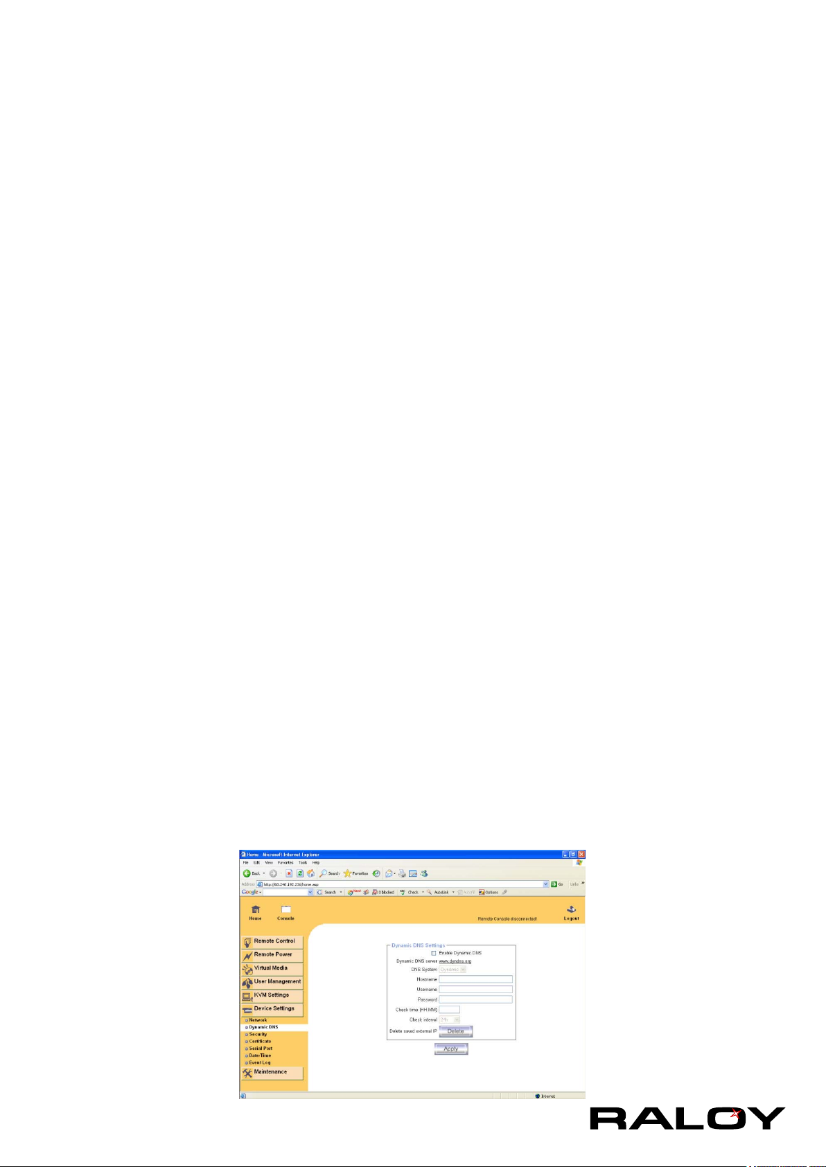
3-4.2 Dynamic DNS
23
Page 27
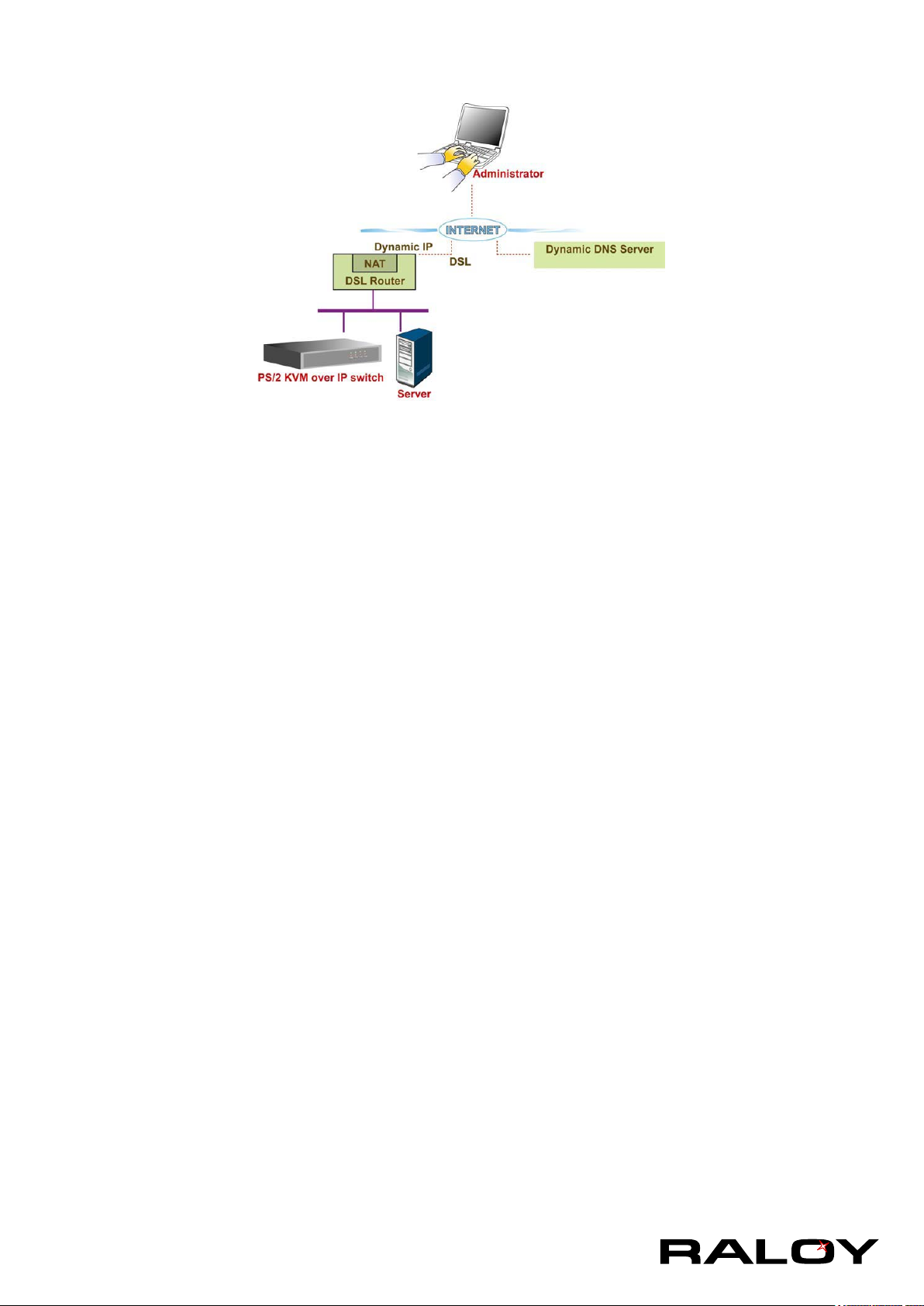
A freely available Dynamic DNS service (www.dyndns.org) can be used in the following scenario:
The IP module is reachable via the IP address of the DSL router, which is dynamically assigned by the
provider. Since the administrator does not know the IP address assigned by the provider, the IP module
connects to a special dynamic DNS server in regular intervals and registers its IP address there. The
administrator may contact this server as well and pick up the same IP address belonging to his card.
The administrator has to register an IP module that is supposed to take part in the service with the Dynamic
DNS Server and assign a certain hostname to it. He will get a nickname and a password in return to the
registration process. This account information together with the hostname is needed in order to determine
the IP address of the registered IP module.
You have to perform the following steps in order to enable Dynamic DNS:
■ Make sure that the LAN interface of the IP module is properly congured.
■ Enter the Dynamic DNS Settings conguration dialog.
■ Enable Dynamic DNS and change the settings according to your needs (see below).
Enable Dynamic DNS
This enables the Dynamic DNS service. This requires a congured DNS server IP address.
Dynamic DNS server
This is the server name where IP module registers itself in regular intervals. Currently, this is a xed
setting since only dyndns.org is supported for now.
DNS System
Choose Dynamic for free DNS service. Custom for your own domain.
Hostname
This is the hostname of the IP module that is provided by the Dynamic DNS Server. (use the whole name
including the domain, e.g. testserver.dyndns.org , not just the actual hostname).
Username
You have registered this username during your manual registration with the Dynamic DNS Server.
Spaces are not allowed in the Nickname.
Password
You have used this password during your manual registration with the Dynamic DNS Server.
24
Page 28
Check time
The IP module registers itself for initiating the IP address of IP module stored in the Dynamic DNS server
at this time.
Check interval
This is the interval for reporting again to the Dynamic DNS server for updating the IP address associated
with the Domain Name of the IP module.
Warning
The IP module has its own independent real time clock. Make sure the time setting of
the IP module is correct. (see the Section called Date And Time)
3-4.3 Security
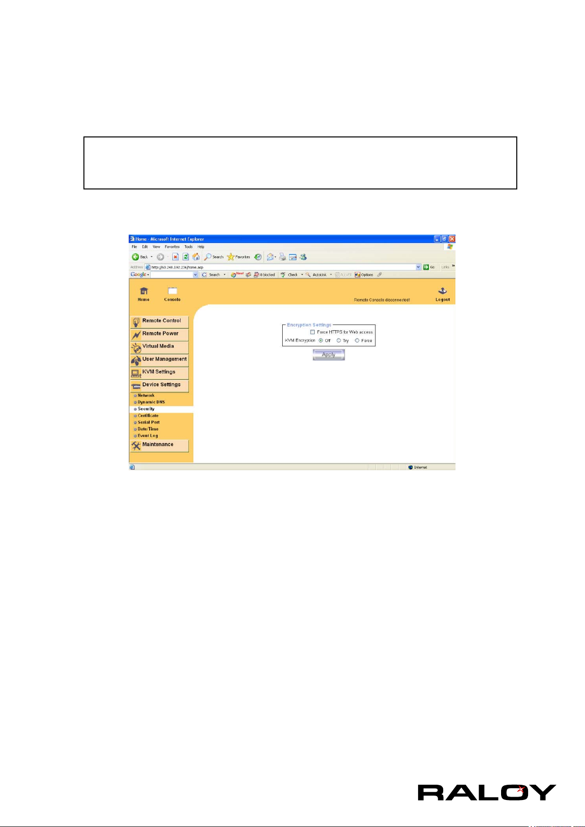
Force HTTPS
f this option is enabled access to the web front-end is only possible using an HTTPS connection. The IP
module will not listen on the HTTP port for incoming connections.
In case you want to create your own SSL certicate that is used to identify the IP module refer to the
Section called Certicate.
KVM Encryption
This option controls the encryption of the RFB protocol. RFB is used by the Remote Console to transmit
both the screen data to the administrator machine and keyboard and mouse data back to the host. If set
to “Off” no encryption will be used.
25
Page 29
3-4.4 Certicate
The IP module uses the Secure Socket Layer (SSL) protocol for any encrypted network trafc between itself
and a connected client. During the connection establishment the IP module has to expose its identity to a
client using a cryptographic certicate. The default certicate comes with IP MODULE device upon delivery
is for testing purpose only. System administrator should not rely on this default certicate as the secured
global access mechanism through Internet.
However, it is possible to generate and install a new base64 X.509 certicate that is unique for a particular
IP module. In order to do that, the IP module is able to generate a new cryptographic key and the
associated Certicate Signing Request (CSR) that needs to be certied by a certication authority (CA). A
certication authority veries that you are the person who you claim you are, and signs and issues a SSL
certicate to you.
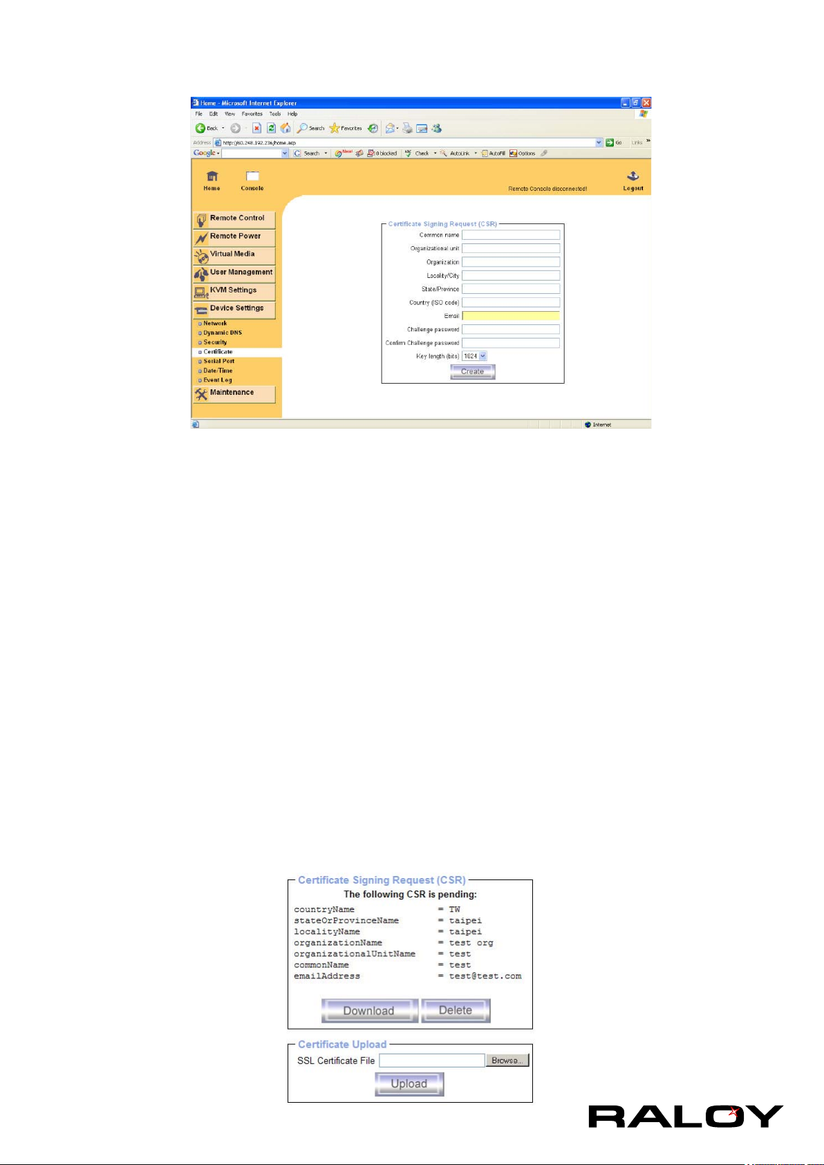
The following steps are necessary to create and install a SSL certicate for the IP
module:
■ Create a SSL Certicate Signing Request using the panel shown below. You need to ll out a number
of elds that are explained below. Once this is done, click on the button “Create” which will initiate the
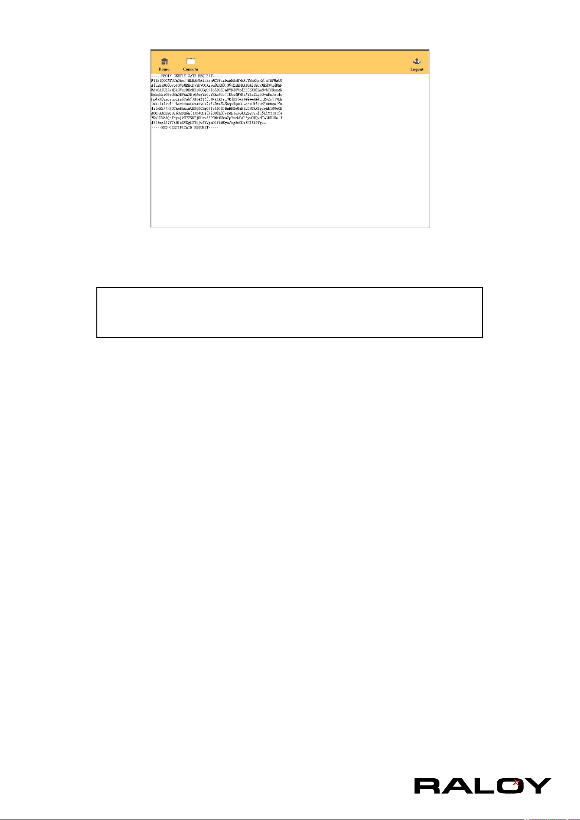
Certicate Signing Request generation. The CSR can be downloaded to your administration machine
with the “Download CSR” button.
■ Send the saved CSR string to a CA for certication. You will get the new certicate from the CA after a
more or less complicated traditional authentication process (depending on the CA).
■ Upload the certicate to the IP module using the “Upload” button as shown below.
26
Page 30
This is the interval for reporting again to the Dynamic DNS server for updating the IP address associated
with the Domain Name of the IP module.
Warning
The IP module has its own independent real time clock. Make sure the time
setting of the IP module is correct. (see the Section called Date And Time)
Common Name
This is the network name of the IP module once it is installed in the user’s network (usually the fully
qualied domain name). It is identical to the name that is used to access the IP module with a web
browser (without the “http://” prex). In case the name given here and the actual network name differ, the
browser will pop up a security warning when the IP module is accessed using HTTPS.
Organizational Unit
This eld is used for specifying to which department within an organization the IP module belongs.
Organization
The name of the organization to which the IP module belongs.
Locality/City
The city where the organization is located.
State/Province
The state or province where the organization is located.
Country (ISO code)
The country where the organization is located. This is the two-letter ISO code, e.g. DE for Germany, or
US for the USA. (Note: the country code has to be entered in CAPITAL LETTERS.)
Challenge Password
Some certication authorities require a challenge password to authorize later changes on the certicate
(e.g. revocation of the certicate). The minimal length of this password is 4 characters.
Conrm Challenge Password
Conrmation of the Challenge Password
Email
The email address of a contact person that is responsible for the IP module and its security.
27
Page 31
Key length
This is the length of the generated key in bits. 1024 Bits are supposed to be sufcient for most cases.
Longer keys may result in slower response time of the IP module during connection establishment.
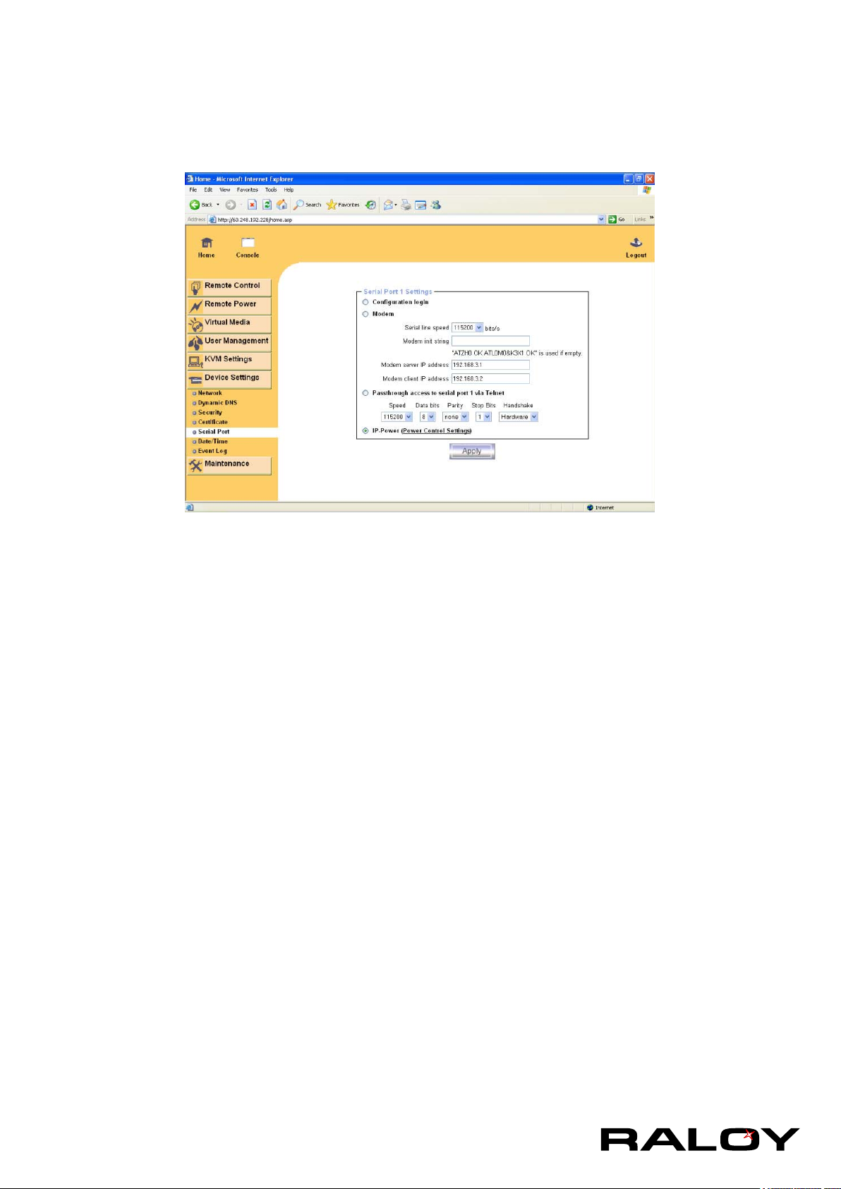
3-4.5 Serial Port
The IP module Serial Settings allows you to specify what device is connected to the serial port and how to
use it.
Conguration or console login
Do not use the serial port for any special function, use it only for the initial conguration.
Modem
The IP module offers remote access using a telephone line in addition to the standard access over the
built-in Ethernet adapter. The modem needs to be connected to the serial interface of the IP module.
Logically, connecting to the IP module using a telephone line means nothing else than building up a
dedicated point-to-point connection from your console computer
to the IP module. In other words, the IP module acts as an Internet Service
Provider (ISP) to which you can dial in. The connection is established using the
Point-to-Point Protocol (PPP). Before you connect to the IP module, make sure to
congure your console computer accordingly. For instance, on Windows based
operating systems you can congure a dial-up network connection, which defaults
to the right settings like PPP.
The Modem Settings panel allows you to congure the remote access to the IP
module using a modem. The meaning of each parameter will be described below.
The modem settings are part of the serial settings panel.
Serial line speed
The speed the IP module is communicating with the modem. Most of all modems available today
will support the default value of 115200 bps. In case you are using an old modem and discovering
problems try to lower this speed.
28
Modem Init String
The initialization string used by the IP module to initialize the modem. The default value will work
with all modern standard modems directly connected to a telephone line. In case you have a special
modem or the modem is connected to a local telephone switch that requires a special dial sequence
in order to establish a connection to the public telephone network, you can change this setting by
Page 32
giving a new string. Refer to the modem’s manual about the AT command syntax.
Modem server IP address
This IP address will be assigned to the IP module itself during the PPP handshake. Since it is a
point-to-point IP connection virtually every IP address is possible but you must make sure, it is not
interfering with the IP settings of the IP module and your console computer. The default value will
work in most cases.
Modem client IP address
This IP address will be assigned to your console computer during the PPP handshake. Since it is a
point-to-point IP connection virtually every IP address is possible but you must make sure, it is not
interfering with the IP settings of the IP module and your console computer. The default value will
work in most cases.
Passthrough access to serial port via Telnet
Using this option, it is possible to connect an arbitrary device to the serial port and access it (assuming it
provides terminal support) via Telnet. Select the appropriate options for the serial port and use the Telnet
Console, or a standard Telnet client to connect to the IP module.
3-4.6 Date and Time
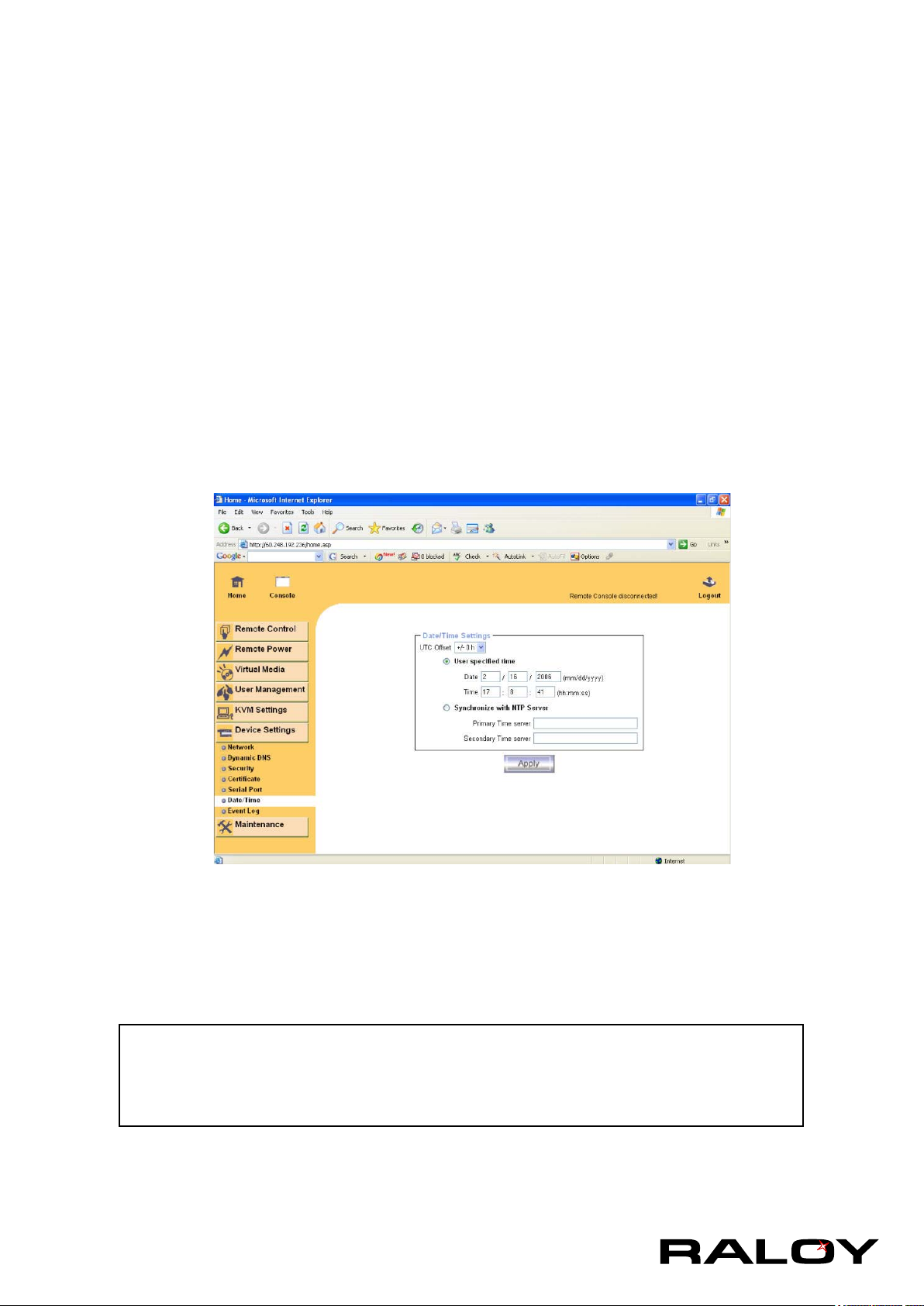
This link refers to a page, where the internal real-time clock of the IP module can be set up (see Figure
3-32). You have the possibility to adjust the clock manually, or to use a NTP timeserver. Without a
timeserver, your time setting will not be persistent, so you have to adjust it again, after IP module loses
power for more than a few minutes. To avoid this, you can use a NTP timeserver, which sets up the internal
clock automatically to the current UTC time. Because NTP server time is always UTC, there is a setting that
allows you to set up a static offset to get your local time.
Warning
There is currently no way to adjust the daylight saving time automatically. So you
have to set up the UTC offset twice a year properly to the local rules of
your country.
29
Page 33
3-4.7 Event Log
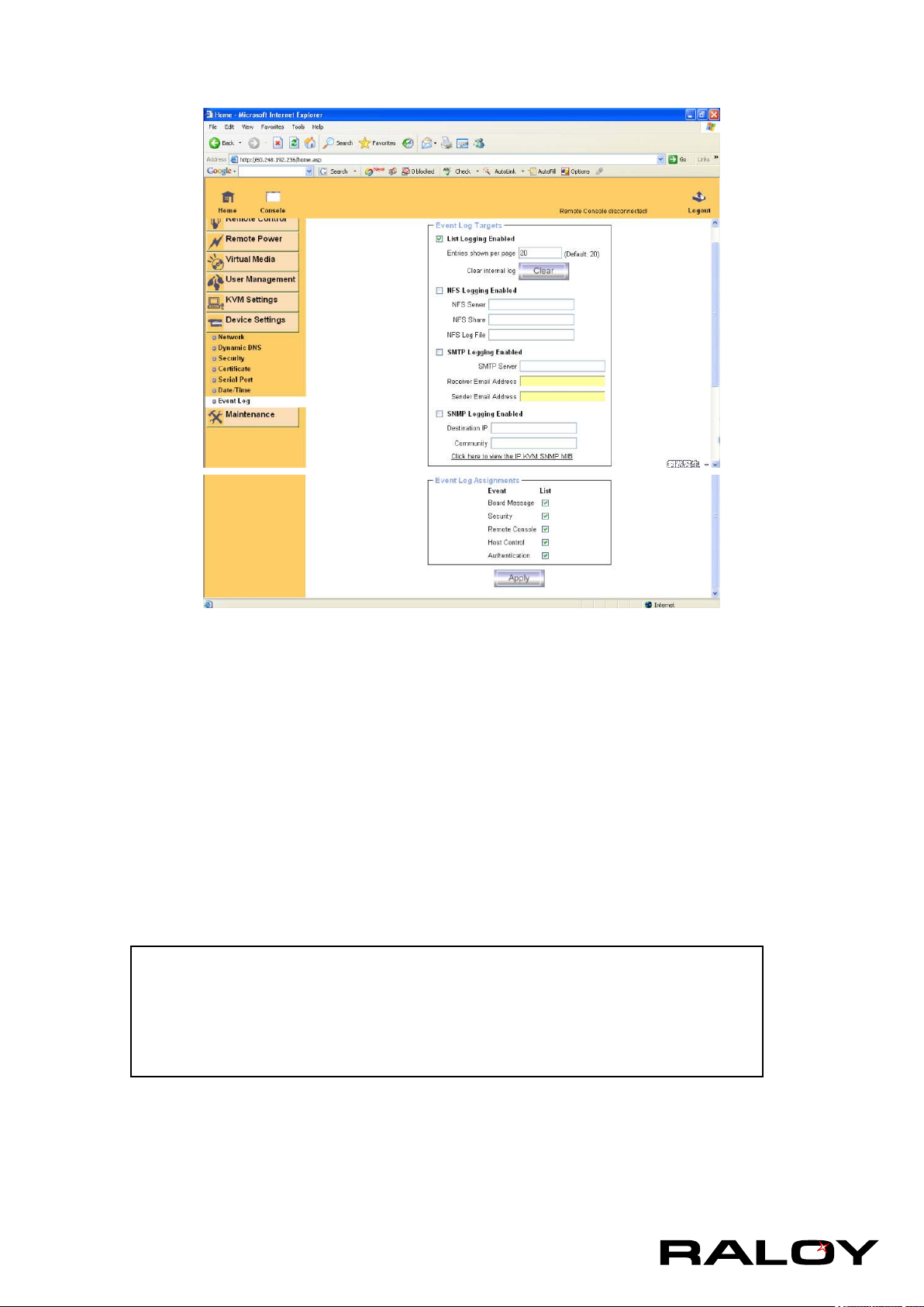
Important events like a login failure or a rmware update are logged to a selection of logging destinations.
Each of those events belongs to an event group, which can be activated separately.
The common way to log events is to use the internal log list of the IP module. To show the log list, click on
“Event Log” on the “Maintenance” page. In the Event Log Settings you can choose how many log entries
are shown on each page. Furthermore, you can clear the log le here.
List logging enabled
The common way to log events is to use the internal log list of the IP module . To show the log list, click
on “Event Log” on the “Maintenance” page.
Since the IP module’s system memory is used to save all the information, the maximum number of
possible log list entries is restricted to 1.000 events. Every entry that exceeds this limit overrides the
oldest one, automatically.
Warning
If the reset button on the HTML frontend is used to restart the IP module, all
logging information is saved permanently and is available after the IP module
has been started. If the IP module loses power or a hard reset is performed, all
logging data will be lost. To avoid this, use one of the following log methods.
NFS Logging Enabled
Dene a NFS server, where a directory or a static link have to be exported, to write all logging data to a
le that is located there. To write logging data from more than one IP module devices to only one NFS
share, you have to dene a le name that is unique for each device. When you change the NFS settings
and press the button “Apply” , the NFS share will be mounted immediately. That means, the NFS share
and the NFS server must be lled with valid sources or you will get an error message.
30
Page 34

SMTP Logging enabled
With this option, the IP module is able to send Emails to an address given by the Email address text eld
in the Event Log Settings. These mails contain the same description strings as the internal log le and
the mail subject is lled with the event group of the occurred log event. In order to use this log destination
you have to specify a SMTP server, that has to be reachable from the IP module device and that needs
no authentication at all (<serverip>:<port>).
SNMP Logging enabled
If this is activated, the IP module sends a SNMP trap to a specied destination IP address, every time a
log event occurs. If the receiver requires a community string, you can set it in the appropriate text eld.
Most of the event traps only contain one descriptive string with all information about the log event. Only
authentication and host power events have an own trap class that consists of several elds with detailed
information about the occurred event. To receive this SNMP traps, any SNMP trap listener may be used.
Here is a example of all gerenated event and its event group.
Device succesfully started device
Board Reset performed by user... device
Firmware upload failed. device
No rmware le uploaded. device
Uploaded rmware le discarded. device
Firmware validation failed. device
Firmware le uploaded by user... device
Firmware updated by user... device
Internal log le cleared by user... device
Security Violation security
Host Power host
Host Reset host
Connection to Remote Console failed: reason. console (several)
Connection to client ... established. console
Connection to client ... closed. console
Login failed. auth
Login succeed. auth
Warning
In contrast to the internal log le on the IP module, the size of the NFS log le
is not limited. Every log event will be appended to the end of the le so it grows
continuously and you may have to delete it or move it away from time to time.
31
Page 35
3-5 Maintenance
3-5.1 Device Information
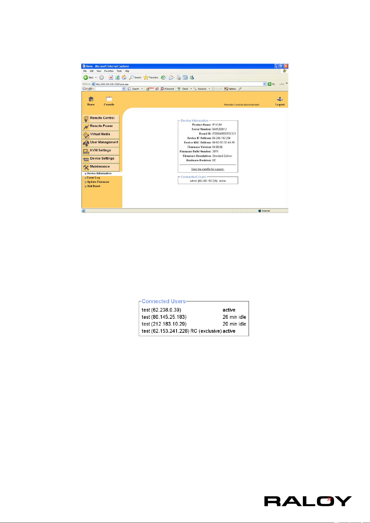
Device Summary
This section contains a summary with various information about this IP module and it’s current rmware
and allows you to reset the card.
The Data le for support allows you to download the IP module data le with specic support information.
This is an XML le with certain customized support information like the serial number etc. You may
send us this information together with a support request. It will help us to locate and solve your reported
problem.
The image above displays the IP module activity. From left to right the connected user(s), its IP address
(from which host the user comes from) and its activity status is displayed. RC means that the Remote
Console is open. If the Remote Console is opened in exclusive mode the term (exclusive mode) is
added. For more information about this option see the Section called Remote Console Control Bar in
Chapter 5. To display the user activity the last column contains either the term active for an active user or
30 min idle for an user who is inactive for a certain amount of time.
32
Page 36
3-5.2 Event Log
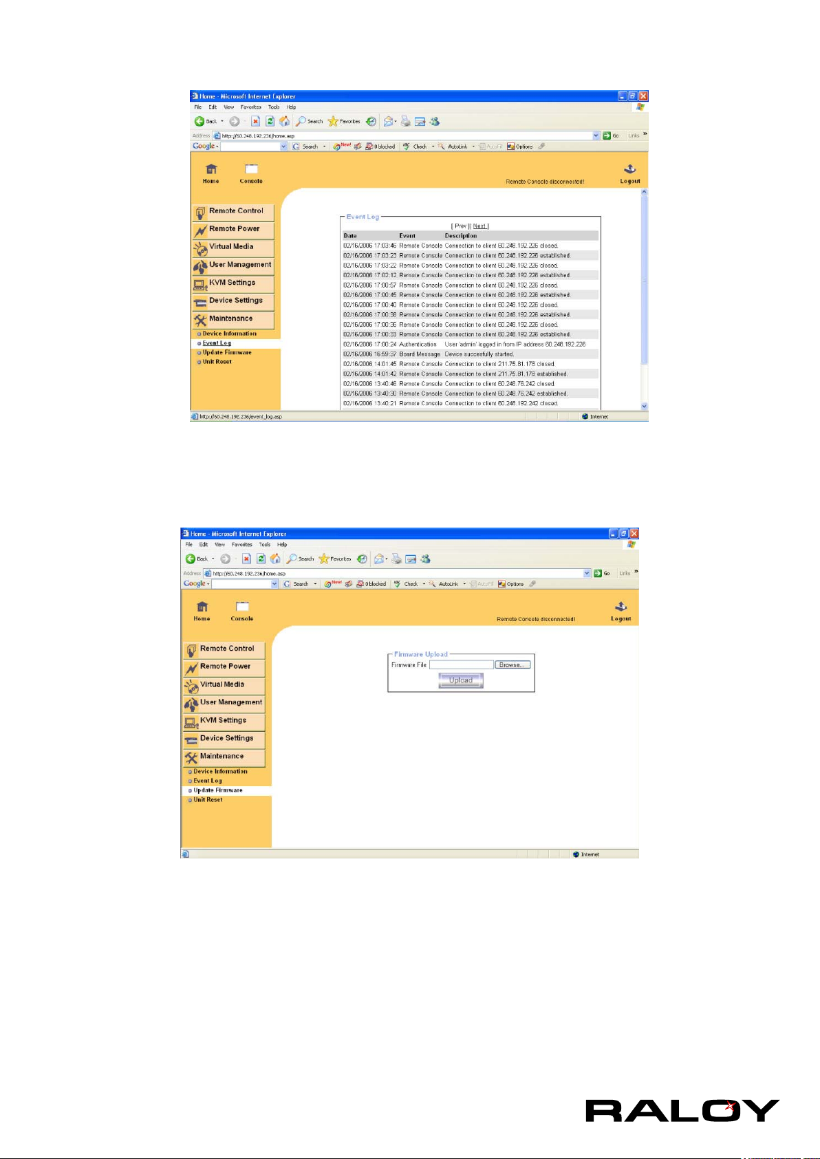
The image above displays the log list including the events that are logged by the IP module.
3-5.3 Update FIrmware
3-7.3 Update Firmware
The IP module is a complete standalone computer. The software it runs is called rmware. The rmware of
the IP module can be updated remotely in order to install new functionality or special features.
A new rmware update is a binary le which will be sent to you by email or which you can download from
the supplier web site. If the rmware le is compressed (le sufx .zip) then you must unzip it before you
can proceed. Under the Windows operating system you may use WinZip from http://www.winzip.com/ for
decompression. Other operating systems might provide a program called unzip.
Before you can start updating the rmware of your IP module the new uncompressed rmware le has to be
accessible on the system that you use for connecting to the IP module.
33
Page 37
Updating the rmware is a three-stage process:
1. Firstly, the new firmware file is uploaded onto the IP module. In order to do that you need to select the
file on your local system using the button “Browse” of the Upload Firmware panel. Once the firmware
file has been uploaded, it is checked whether it is a valid firmware file and whether there were any
transmission errors. In case of any error the Upload Firmware function will be aborted.
2. Secondly, if everything went well, you see the Update Firmware panel. The panel shows you the
version number of the currently running firmware and the version number of the uploaded firmware.
Pressing the button “Update” will store the new version and substitute the old one completely.
Warning
This process is not reversible and might take some minutes. Make sure the IP
module’s power supply will not be interrupted during the update process,
because this may cause an unusable card.
3. Thirdly, after the firmware has been stored, the panel will request you to reset the IP module manually.
Half a minute after the reset, the IP module will run with the new firmware version and should be
accessible. However, you are requested to login once again.
Warning
The three-stage rmware update process and complete consistency check are
making a mistake in updating the rmware almost impossible. However, only
experienced staff members or administrators should perform a rmware update.
Make sure the IP module’s power supply will not be interrupted!
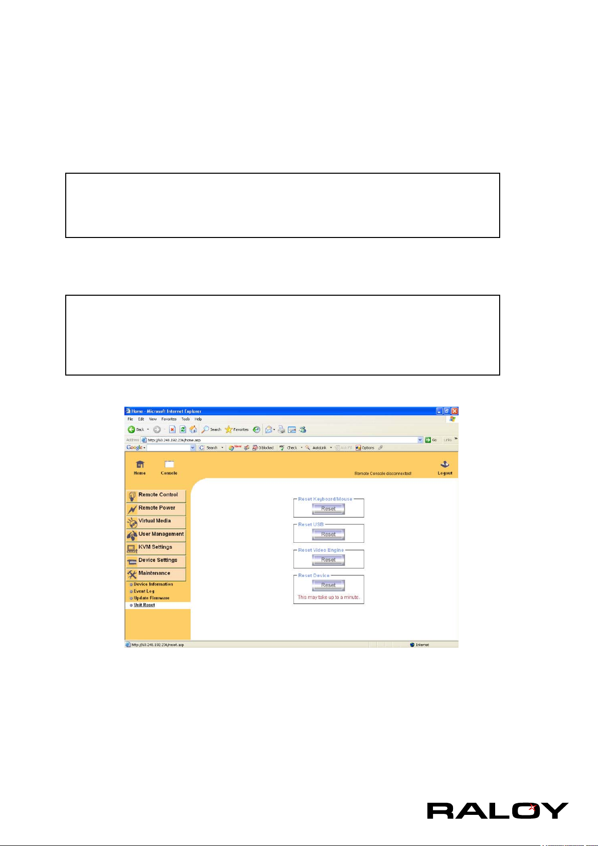
3-5.4 Unit Reset
This section allows you to reset specic parts of the device. This involves the both keyboard and mouse,
the video engine and the IP module itself. Resetting the card itself is mainly needed to activate a newly
updated rmware. It will close all current connections to the administration console and to the Remote
Console.
The whole process will take about half a minute. Resetting sub devices (e.g. video engine) will take some
seconds only and does not result in closing connections. To reset a certain IP module functionality click on
the button Reset as displayed in the image above.
Note: Only the super user is allowed to reset the IP module.
34
Page 38

4 Troubleshooting
The remote mouse doesn’t work or is not synchronous
Make sure the mouse settings in IP module match the mouse model. There are some circumstances where
the mouse synchronization process could behave incorrectly, refer to Sections 2.4.1 & 3.5.22 for further
explanation.
The video quality is bad or the picture is grainy
Try to correct the brightness and contrast settings (see Sections 5.4.1 & 6.5.3) until they are out of a range
where the picture looks grainy. Use the auto adjustment feature to correct a ickering video.
Login on IP module fails.
Was the correct combination of user and password given? On delivery, the user ”super” has the password
”pass”. Moreover your browser must be congured to accept cookies.
The Remote Console window can’t connect to IP module.
Possibly a rewall prevents access to the Remote Console. Make sure the TCP port
numbers 443 or 80 are open for incoming TCP connection establishments.
No connection can be established to IP module.
Check whether the network connection is working in general (ping the IP address of IP module). If not, check
network hardware. Is IP module powered on? Check whether the IP address of IP module and all other IP
related settings are correct! Also verify that all the IP infrastructure of your LAN, like routers etc., is correctly
congured. Without a ping functioning, IP module can’t work either.
Special key combinations, e.g. ALT+F2, ALT+F3 are intercepted by the console system and not
transmitted to the host.
You have to dene a so-called ’Button Key’. This can be done in the Remote Console settings.
In the browser the IP module pages are inconsistent or chaotic.
Make sure your browser cache settings are feasible. Especially make sure the cache settings are not set to
something like ”never check for newer pages”. Otherwise IP module pages may be loaded from your browser
cache and not from the card.
Windows XP doesn’t awake from standby mode
This is possibly a Windows XP problem. Try not to move the mouse while XP goes in standby mode.
Can’t upload the signed certicate in MacOS X
If an ’internal error’ occurs while uploading the signed certicate either change the extension of the le to .txt
or add a le helper using the Internet Explorer preferences for this type of le. Make sure that the encoding is
plain text and the checkbox ’use for outgoing’ is checked. Another possibility is to use a Mozilla based browser.
Every time I open a dialog box with some buttons the mouse pointers are not synchronous anymore
Please check, if you have an option like ”Automatically move mouse pointer to the default button of dialog
boxes” enabled in the mouse settings of the operating system. This option needs to be disabled.
35
Page 39
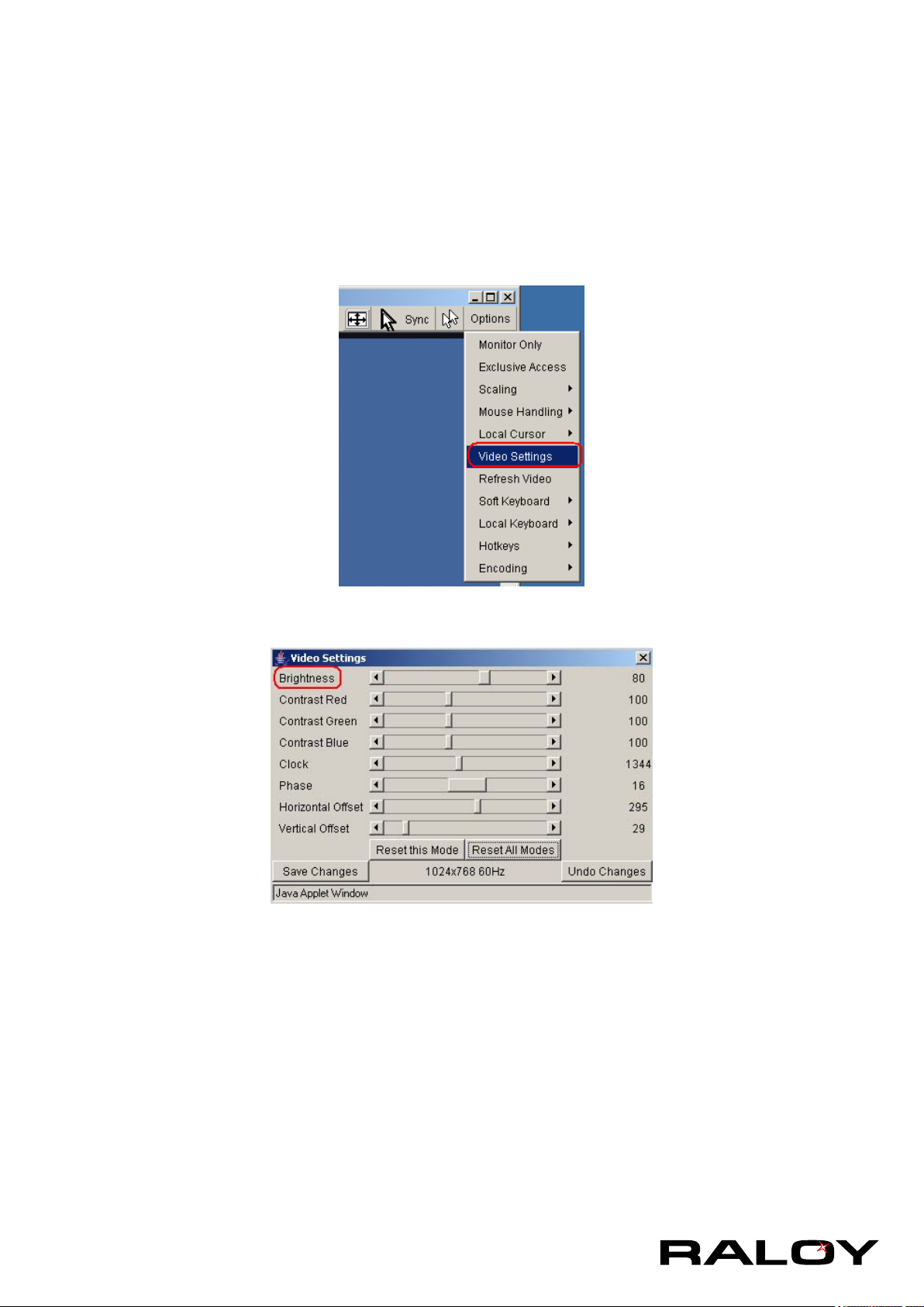
5 Frequently Asked Questions
The color of remote console displaying a pinkish tint.
If you are experiencing the remote control screen displaying a pinkish tint with some graphic cards, please try
adjusting the brightness of the remote console by following steps below.
1. Click Video Settings in Options menu of the remote console.
2. Adjust the Brightness setting until the pinkish tint is reduced or eliminated.
Does any software require on servers which connect to the IP module?
No, the IP module is a 100% hardware solution. No extra software require on servers.
What operating systems does IP module support?
The IP module supports Windows 98, Windows ME, Windows 2000, Windows XP, Unix, Unix-like Operating
System (Sun Solaris, Linux) and Mac OSX.
What browsers does IP module support?
The IP module support Microsoft Internet Explorer version 6.0 or higher, Netscape 7.0 and Mozilla 1.6
Does the IP module work with other brand’s KVM switch?
Yes, the IP module can work with most standard KVM.
How many letters the username and password can be set on IP module?
The IP module accepts 32 letters of username and password.
36
Page 40

How many concurrent user of IP module?
The IP module accepts 15 concurrent users.
How many bits of connection encrypted of IP module?
The IP module provides AES 256 bits connection encrypted.
Local mouse and remote mouse didn’t sync after doing mouse Intelligent Sync.
Please don’t put window on left-up corner of remote console of IP module. Intelligent Sync has to recalculate
the coordinate of mouse from left-up corner on remote console.
37
Page 41
6 Addendum
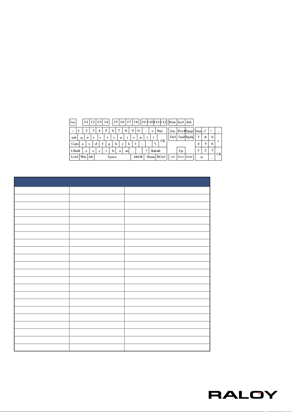
A. Key Codes
The table below shows the key codes used to denes keystrokes or hotkeys for several functions. Please note
that these key codes do not represent necessarily key characters that are used on international keyboards.
They name a key on a standard 104 key PC keyboard with an US English language mapping. The layout for
this keyboard is shown in the image below. However, most modier keys and other alphanumeric keys used
for hotkey purposes in application programs are on an identical position, no matter what language mapping
you are using. Some of the keys have aliases also, means they can be named by 2 key codes (separated by
comma in the table).
Key (and aliases)
0-9 SPACE PAGE DOWN
A - Z ALTGR UP
, TILDE ESCAPE, ESC LEFT
-, MINUS F1 DOWN
=, EQUALS F2 RIGHT
; F3 NUM LOCK
‘ F4 NUMPAD0
<, LESS F5 NUMPAD1
, F6 NUMPAD2
. F7 NUMPAD3
/, SLASH F8 NUMPAD4
BACKSPACE F9 NUMPAD5
TAB F10 NUMPAD6
[ F11 NUMPAD7
] F12 NUMPAD8
ENTER PRINTSCREEN NUMPAD9
CAPS LOCK SCROLL LOCK NUMPADPLUS, NUMPAD PLUS
\, BACK SLASH BREAK NUMPAD/
LSHIFT, SHIFT INSERT NUMPADMUL, NUMPAD MUL
RCTRL HOME NUMPADMINUS, NUMPAD MINUS
LCTRL, CTRL DELETE WINDOWS
LALT, ALT END MENU
38
Page 42
B. Video Modes
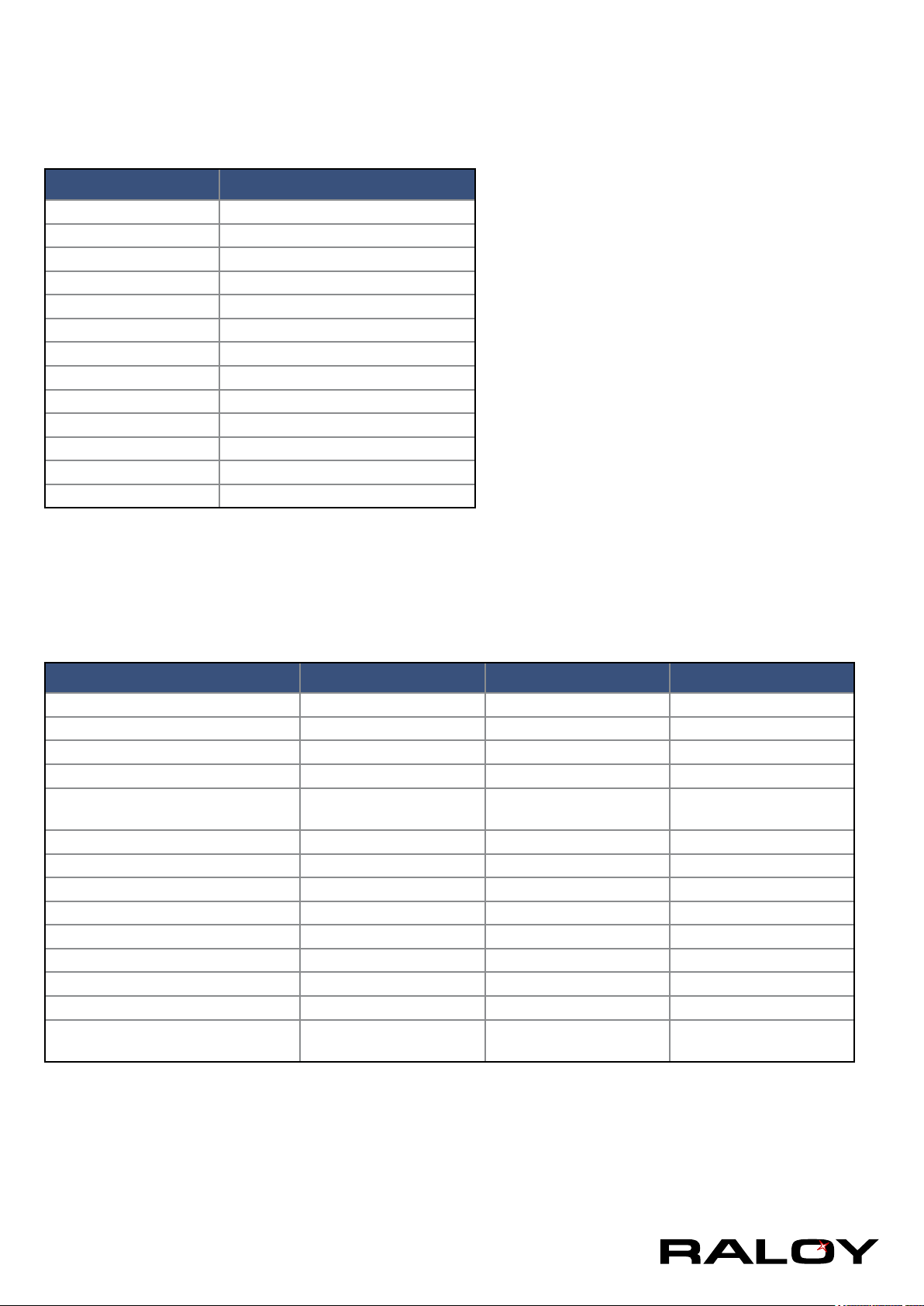
The table below lists the video modes IP module supports. Please don’t use other custom video settings
besides of these. If done so, IP module may not be able to detect them.
Resolution (x, y) Refresh Rates
640 x 350 70, 85
640 x 400 56, 70, 85
640 x 480 60, 72, 75, 85, 90, 100, 120
720 x 400 70, 85
800 x 600 56, 60, 70, 72, 75, 85, 90, 100
832 x 624 75
1024 x 768 60, 70, 72, 75, 85, 90, 100
1152 x 864 75
1152 x 864 75
1152 x 870 75
1152 x 900 66
1280 x 960 60
1280 x 1024 60, 75
C. User Role Permissions
The table below lists the user role permissions granted for three user role groups: “Superuser”, “Administrator”,
and “User” .
User Administrator Superuser
Remote Control: KVM x x x
Remote Control: Remote Power - x x
Remote Control: Telnet Console x x x
Virtual Media x x x
User Management: Change Password
User Management: Users - - x
KVM Settings: User Console x (w/o Misc Settings) x x
KVM Settings: Keyboard/Mouse - x x
KVM Settings: Video - x x
Device Settings - - x
Maintenance: Device Information x x x
Maintenance: Event Log - - x
Maintenance: Update Firmware - - x
Maintenance: Unit Reset Keyboard/Mouse, Video Keyboard/Mouse, Video
x x x
Keyboard/Mouse, Video,
Device
39
Page 43
D. IP Module Port Table
Port Protocol Purpose
23 Telnet over TCP Web & Telnet Client
80 HTTP over TCP Web
443 HTTPS over TCP Web
443 RFB over TCP Remote Console
443 HTTPS over TCP Drive Redirection
139 SMB over TCP CD-ROM Image (Samba Service)
139 SMB over TCP Floppy disk (Samba Service)
1024 SMB over TCP Samba Service source port
162 SNMP over TCP SNMP trap reception port
1024 SNMP over TCP SNMP source port
443 RFB over TCP Remote Keyboard and Mouse data
E. Bandwidth Consumption
The precongured network speed selection simply results in a different Compression and Color Depth
conguration in order to match the different bandwidth limitations of the network type (UMTS, ISDN, etc.)
The following suggested network bandwidth planning table for IP MODULE installation is from the test results
with 3D-Labyrinth screen saver at Resolution 800x600, the worst case consuming the highest network
bandwidth.
Compression
Video Optimized Video Optimized 8 bit 3.0 - 3.3 MB/s
Video Optimized
(high color)
LAN (high color) 0 (no compression) 16 bit 1.0 - 1.3 MB/s Uncompressed video data
LAN 0 (no compression) 8 bit 500 - 700 kb/s Uncompressed video data
DSL 2 8 bit 110 - 140 kb/s Slower video because of compression
UMTS 4 8 bit 80 - 100 kb/s Slower video because of compression
ISDN 128k 6 4 bit 20 - 30 kb/s 16 colors
ISDN/Moden V.90 7 2 bit 13 - 17 kb/s Gray scale
GPRS/HSCSD 8 2 bit 5 - 7 kb/s Gray scale
GSM Modem 9 (best compression) 1 bit 1 - 3 kb/s Black&White Video
Video Optimized 16 bit 4.3 - 5.0 MB/s
Color
Depth
Used
Bandwidth
Notes
Uncompressed, synchronized video data,
most bandwidth needed
Uncompressed, synchronized video data,
most bandwidth needed
40
Page 44
F. Cable Diagrams
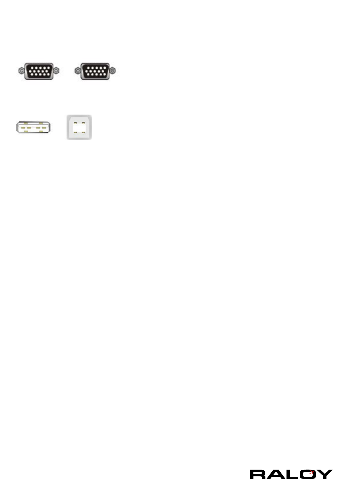
VGA Cable:
HDB 15-pin Male to Male
USB 2.0 Cable:
USB A-B Cable
41
 Loading...