

Page 1
Features
• Module Size: 55 x 72 mm (Smaller than Smart Card)
• Microcontroller: Atmel ARM9
• SDRAM: 128 Mbits
• Flash: Atmel DataFlash
• Fingerprint Sensor: Atmel FingerChip
• Operating Temperature Range: -30° C to +65° C
• Operating Voltage: 3.3V ±10%
• Power Consumption: 200 mA in Typical Conditions
• Operating System: Linux
• Available interfaces on Extension Connector:
– Drivers Provided for SPI, Ethernet, Serial DBGU
– Drivers not Provided for USB Host and Device, TWI, RS-485, IrDA,
SmartCard, MMC/SD Card, SSC, RTC, JTAG…
• Software Suite with Embedded Pre-loaded Bio-engine
®
-based AT91RM9200
®
32 Mbits
®
(Kernel 2.4.19)
®
AT77C101B-CB02V
Description
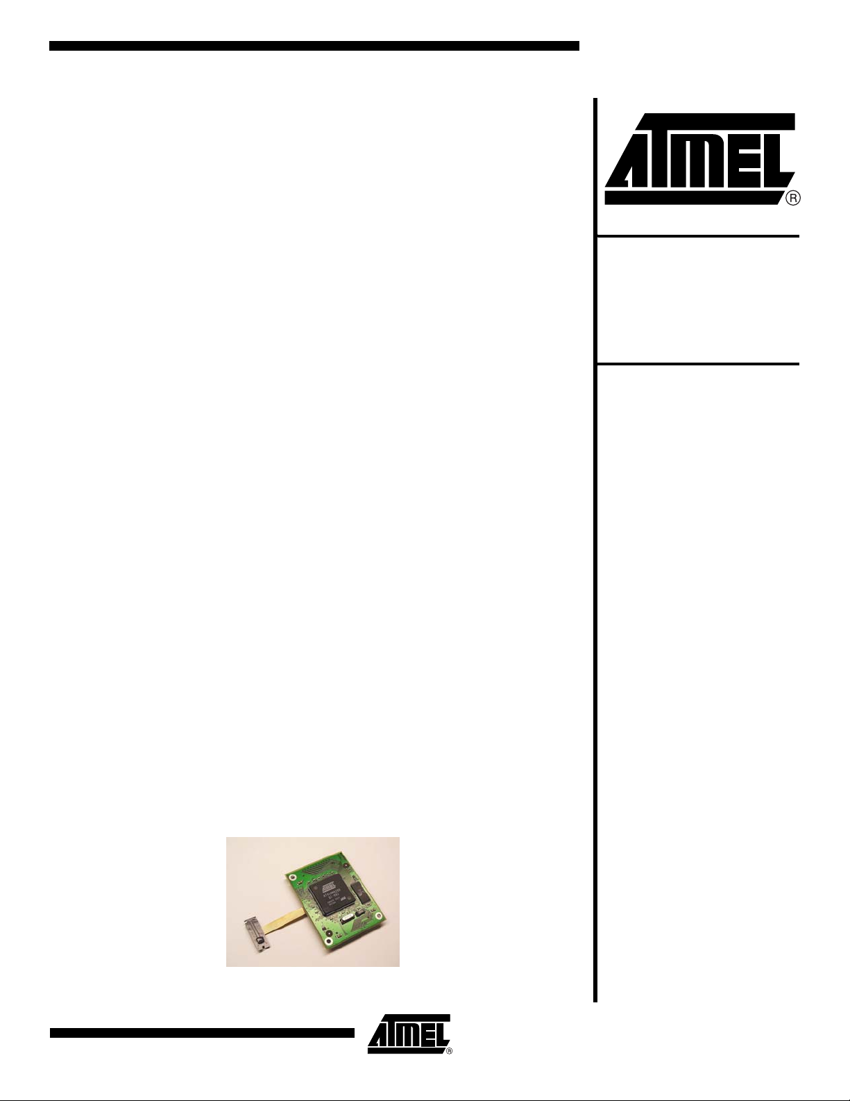
This document describes the specifications of Atmel's AT77SM0101BCB02VKE FingerChip biometric module. Based on Atmel's FingerChip fingerprint sensor, ARM9
microcontroller and flash memory, the AT77SM0101BCB02VKE provides the main
biometric functions such as user enrollment, authentication and identification in a
packaged module, making it easy to integrate into a final system.
The AT77SM0101BCB02VKE is particularly well-suited to Physical Access Control,
Point of Sale devices, Time and Attendance or Vending Machines.
FingerChip®
Biometric
Module
AT77SM0101BCB02VKE
The AT77SM0101BCB02VKE provides great flexibility because of its memory capacity and powerful microcontroller loaded with the Linux operating system, and features
many possible interfaces, including Ethernet. The AT77SM0101BCB02VKE biometric
module requires the purchase of the Evaluation/Development Kit
AT77SM0101BCB02VEK to develop the user interface of the final application.
Applications
• Physical Access Control
• Time and Attendance Systems
• Automated Teller Machines, Points of Sale
• Vending Machines
•Smart Homes
• Locks, Safes
• Reference Design for ARM9 and FingerChip Design Development
Figure 1. FingerChip Biometric Module AT77SM0101BCB02VKE
5391A–BIOM–09/04
Page 2
Functional Description
The AT77SM0101BCB02VKE is a biometric sub-system based on Atmel’s FingerChip
fingerprint sensor. It comprises a fingerprint sensor connected to a board that embeds
processing capabilities through an ARM9-based AT91RM9200 microprocessor, and
memory to store the software and fingerprint templates.
The biometric module must be connected to a motherboard for power supplies and
interface connections. Connection to the motherboard is achieved through two standard
connectors located on the sides of the module board.
The module is loaded with a Linux operating system, an Atmel driver for the FingerChip
sensor, and by default, authentication software (biometric library) for extraction of fingerprint characteristics and comparison with enrolled templates (also called bio-engine).
The standalone module can perform the following:
• Enrollment: an operation where the end-user scans his fingerprint by sweeping it
across the FingerChip sensor, providing a fingerprint signature reference (template)
• Authentication: accurate matching of the newly acquired fingerprint against the
template stored in the board’s memory during the enrollment procedure, used to
validate user authentication
• Identification: matching of the fingerprint image against the correct template within a
database of previously acquired templates
These three functions can then be used in any application requiring authentication to
grant rights to a user, or to change criteria of the user’s profile. Examples of typical
applications might include physical access control or time and attendance monitoring.
The AT77SM0101BCB02VEK Evaluation Kit provides all the tools necessary for easy
development of a customized application using the biometric module APIs.
The AT77SM0101BCB02VKE biometric module lets you add convenient and secured
user authentication to your products in a surprisingly reduced development time.
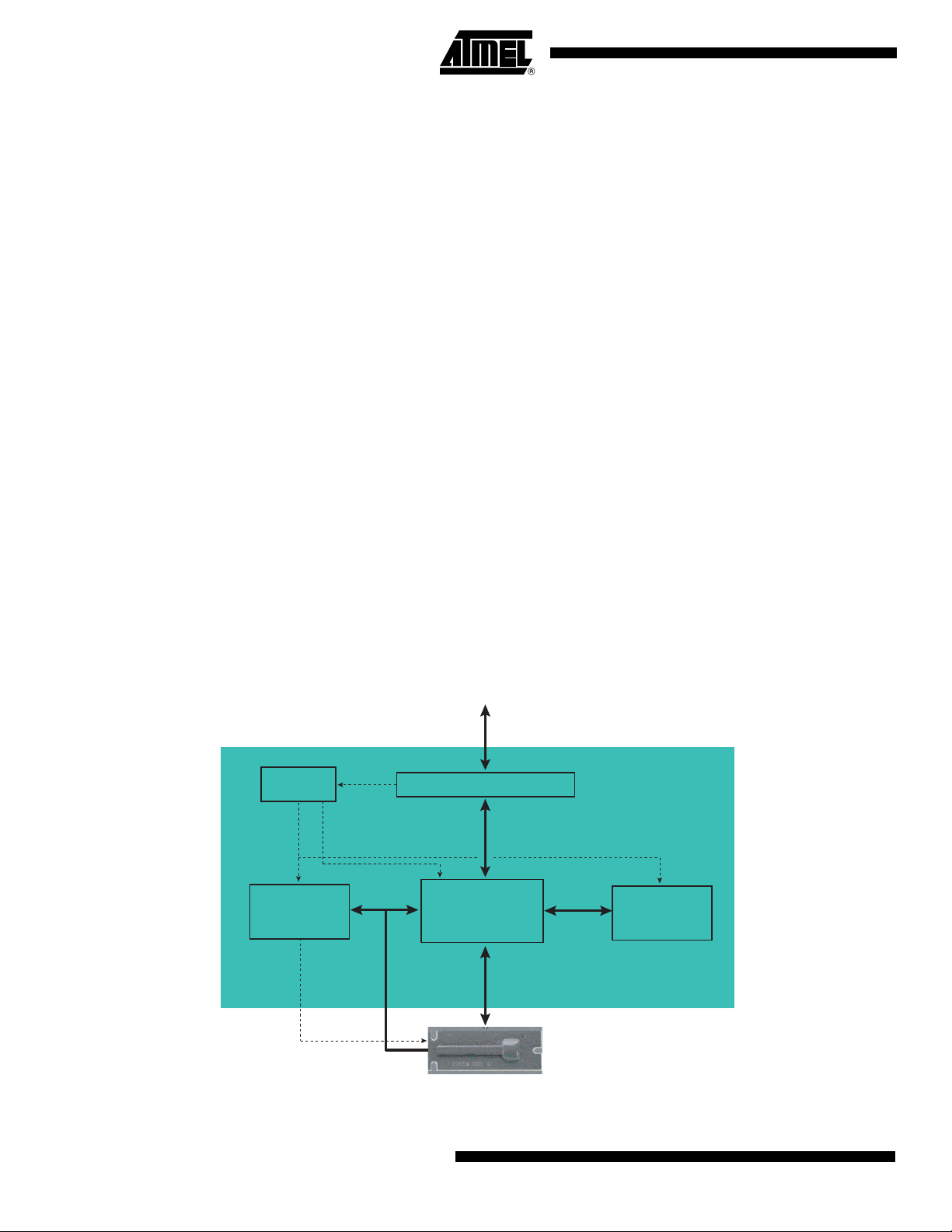
Figure 2. AT77SM0101BCB02VKE Block Diagram
Linear
Regulator
3.3V
SDRAM
16 MB
3.3V
1.8V
32-bit
Data Bus
8 Bits
Motherboard
Connectors
GPIOS Interfaces
AT91RM9200
Control
SPI
Flash
4 MB
AT77C101B-CB02V
2
AT77SM0101BCB02VKE
5391A–BIOM–09/04
Page 3
AT77SM0101BCB02VKE
Technical Description
Module Size and Length of Flex
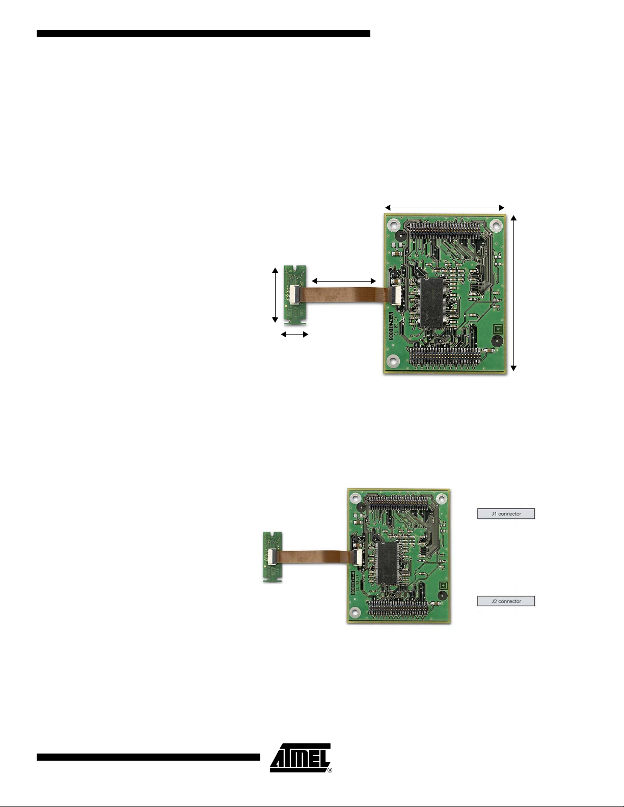
Atmel’s FingerChip biometric module includes the AT77C101B-CB02V FingerChip sensor (8-bit parallel interface) connected through a flex cable to the module itself.
The board size of the module is 55 mm x 72 mm. It has three screw holes for easy fixing
to the motherboard or casing of the final system.
The flexible cable is 5 cm long. It is a single straight cable made of copper.
Figure 3. AT77SM0101BCB02VKE Board Dimensions
55 mm
50 mm
26.6 mm
72 mm
9.85 mm
Description of Motherboard Interface
The dimensions of the sensor are 26.6 mm x 9.85 mm x 2.6 mm for the PCB. The die
size is 1.7 mm x 17.3 mm.
Figure 4. Motherboard Interface
2
1
2
1
50
49
50
49
5391A–BIOM–09/04
3
Page 4

Table 1 . J1 Pin Description
Pin Description Pin Description
1GND2 3V3
3 NBS3 4 NBS1
5 PC10 6 NRD_NOE_NCFOE
7 PC11 8 NWR0_NWE_NCFWE
9 PC12 10 NCS3_NSMCS
11 PC14* 12 PC15*
13 PC1 14 PC0*
15 PC2 16 PC3
17 PC4 18 PC5
19 PC6 20 PA15/EMDC
21 PA0/MISO 22 PA16/EMDIO
23 PA1/MOSI 24 PA17/TXD0
25 PA2/SPCK 26 PA18/RXD0
27 PA4/NPCS1 28 PA19/SCK0
29 PA5/NPCS2 30 PA20/CTS0
31 PA6/NPCS3 32 PA21/RTS0
33 PA7/EREFCK 34 PA22
35 PA8/ETXEN 36 PA23/IRQ3
37 PA9/ETX0 38 PA24
39 PA10/ETX1 40 PA25/TWD
41 PA11/ECRSDV 42 PA26/TWCK
43 PA12/ERX0 44 PA29
45 PA13/ERX1 46 PA28
47 PA14/ERXER 48 PA27
49 3V3 50 GND
Note: Pins 11, 12 and 14: do not use when the AT77C101B is connected to the module.
4
AT77SM0101BCB02VKE
5391A–BIOM–09/04
Page 5

AT77SM0101BCB02VKE
Table 2 . J2 Pin Description
Pin Description Pin Description
1GND23V3
3 PB22 4 PC9
5 PB19 6 PC8
7 PB18 8 PC7
9 PB17 10 DDP
11 PB16 12 DDM
13 PB15 14 HDPA
15 PB14 16 HDMA
17 PB13 18 PB29/IRQ0
19 PB12 20 PB28/FIQ
21 PB11 22 PB27
23 PB10 24 PB26
25 PB9 26 PB25
27 PB8 28 PB24
29 PB7 30 PB23
31 PB6 32 NRST
33 PB5 34 NTRST
35 PB4 36 TMS
37 PB3 38 TCK
39 PB2 40 TDO
41 PB1 42 TDI
43 PB0 44 JTAGSEL
45 PA31 46 PB21
47 PA30 48 PB20
49 3V3 50 GND
The pins are used to connect the following interfaces:
• USB device: pins 10 and 12 of J2 connector
• USB host: pins 14 and 16 of J2 connector
• TWI: pins 40 and 42 of J1 connector
• JTAG: pins 32, 34, 36, 38, 40, 42 and 44 of J2 connector
• SPI: pins 21, 23, 25, 27, 29 and 31 of J1 connector
• Two serial links: RS-232, RS-485, IrDA and/or Smart Card
• Ethernet or MMC/SD card
5391A–BIOM–09/04
5
Page 6

Board’s Main Components
ARM9-based AT91RM9200 Microcontroller
Memory The AT77SM0101BCB02VKE biometric module features:
AT77C101B-CB02V Sensor The sensor has the following characteristics:
The AT91RM9200 microcontroller features the following:
• 200 MIPS capability
• 16 KB data cache
• 16 KB instruction cache
• 16 KB SRAM
• ROM boot
•Ethernet MAC
• USB 2.0 full-speed host and device
• USART, DMA, TWI, SPI, SSC, MCI
The ARM9 operates at 200 MHz on the module.
• 128 Mbits (16 Mbytes) of SDRAM on a 32-bit parallel data bus interface operating at
66 MHz
• 32 Mbits (4 Mbytes) of Atmel DataFlash on an SPI bus operating at 10 MHz
• A sensitive layer over a 0.8 µm CMOS array
• An image zone of 0.4 × 14 mm, equalling 0.02 in. × 0.55 in.
• An image array of 8 × 280, equalling 2240 pixels
• A pixel pitch of 50 µm × 50 µm, equalling 500 dots-per-inch resolution
• A pixel clock of up to 2 MHz with a capacity of up to 1780 frames per second
• A die size of 1.7 × 17.3 mm
• An operating voltage range of 3V to 5.5V
• A natural protection from electrostatic discharge (ESD) up to 16 kV of air discharge.
Use of metal casing or metalized plastic in the final application is strongly
recommended
• A power consumption of 20 mW at 3.3V, 1 MHz, 25°C
• An operating temperature range of -40°C to +85°C
• A strong resistance to abrasion with the capability to withstand over 1 million finger
sweeps
• A sweep speed ranging from 2 cm/s to 20 cm/s
• A low power consumption of 6 mA typical in acquisition mode and 10 µA in standby
mode
6
AT77SM0101BCB02VKE
5391A–BIOM–09/04
Page 7

Storage Capacity
Figure 5. RAM Memory Mapping
AT77SM0101BCB02VKE
16 MB RAM
Used by Ramdisk
6 MB
Figure 6. DataFlash Memory Mapping
16 kB
Compressed
Kernel
700 kB
Kernel
1.5 MB
AT77SM0101BCB02VKE Compressed Ramdisk < 2 MB
Used by Kernel
Code
4 MB 4.5 MB
4 MB DataFlash
Compressed Ramdisk
3 MB
Free
Templates
300 kB
Biometric Performances The device’s biometric performances are characterized by the following:
• An image size of 500 × 400
• 256 levels of grey
• A finger swiping speed from 2 to 15 cm/s
• An FRR under 3% at an FAR 10
• An authentication time of under 10 ms
• A biometric template size of 384 bytes
• An authentication algorithm size of 420 kbytes
• An identification time of under 1 second for 50 templates
-4
rate using an IKENDI® algorithm
Storage
Database
Software
Operating System Driver Modules
5391A–BIOM–09/04
The biometric module comes preloaded with the Linux operating system (kernel 2.4.19
rmk 7). The kernel includes:
• Ramdisk support
• A serial port driver supporting DBGU and up to four UARTs
• An SPI driver
• Ethernet layers 10/100 Mbits (compatible with MII protocol)
• Watchdog support
Further information can be retrieved at http://www.arm.linux.org.uk.
7
Page 8

Two drivers are provided as modules that can be loaded or unloaded during runtime.
These are:
• The FingerChip driver: FingerChip_mod.o, version 2.0 enabling on-the-fly
reconstruction of images
• A GPIOs driver: Leds_mod.o, version 2.0, used to drive switches, LEDS etc.
Environmental Specifications
Operating Conditions
Absolute Maximum Ratings*
Power Supply Voltage (VCC) ................................-0.3V to 4.6V
Storage Temperature (T
) ............................. -40° C to +85° C
stg
*NOTICE: Stresses beyond those listed under “Absolute
Maximum Ratings” may cause permanent damage to the device. This is a stress rating only and
functional operation of the device at these or any
other conditions beyond those indicated in the
operational sections of this specification is not
implied. Exposure to absolute maximum rating
conditions for extended periods may affect
device reliability.
Recommended Conditions of Use
Parameter Symbol Comments Min Typ Max Unit
Positive supply voltage V
Operating temperature range T
CC
amb
3.3V ±10% 3 3.3 3.6 V
Telecom: “T grade” -30° C to +65° C°C
Sensor Resistance
Min Value Standard Method
ESD
Air discharge on die surface (Zap gun), sensor included in casing ±16 kV NF EN 6100-4-2
Mechanical Abrasion
Number of cycles without lubricant
[a multiplication by a factor of 20 should be applied for correlation with a real finger]
Chemical Resistance
Cleaning agents, acid, grease, alcohol, diluted acetone 4 hours Internal method
Note: Resistance characteristics are given for the sensor only.
200,000 MIL E 12397B
Electrical Characteristics
Parameter Symbol Comments Min Typ Max Unit
Current on V
8
CC
AT77SM0101BCB02VKE
I
CC
3.3V ±10% 200 300 mA
5391A–BIOM–09/04
Page 9

AT77SM0101BCB02VKE
Module Integration
Mechanics The size of the board and the flex cable make integrating the standalone module into the
final product simple and convenient. In addition, the module can be fixed to the main
board or the casing using three screws.
Fingerprint Sensor Atmel recommends fixing the sensor by inserting it into the casing’s groove. Care should
be given to ensuring that:
• The casing provides sufficient aeration
• The board is implemented vertically with the flex connector outputs oriented
downwards
• The sensor is protected from direct exposure to rain when used outdoors
Connection of the Module Board to the Motherboard
The standalone module board measures 55 mm by 72 mm. It has three screw holes for
easy fixing to the motherboard or casing of the final system. Connection to the motherboard is achieved through two connectors each comprising 2 x 25 pins, which are
located on the sides of the module board. The height of the components under the module must not exceed 5 mm.
Figure 7. Module Board Mechanical Data
72 mm
Component Side
ATMEL
55 mm
3 mm
5.5 mm
4.5 mm
56.00
56.00
11.6 mm
Solder Side
2
1
49
50
1
2
49 50
J1J2
5391A–BIOM–09/04
42.11
12.90
8.00
8.00
9
Page 10

Electrical Integration The motherboard must at least provide power supplies and the required components in
order to implement the desired interfaces. Atmel recommends using a linear power supply of 3.3V to power the standalone module.
An example of a possible implementation is given in the Development Kit documentation (this kit can be ordered through your local Atmel distributor). Reading this
documentation is strongly recommended to proceed with accurate programming of the
board application.
10
AT77SM0101BCB02VKE
5391A–BIOM–09/04
Page 11

Evaluation and Development Kit
Figure 8. AT77SM0101BCB02VEK
AT77SM0101BCB02VKE
AT77SM0101BCB02VEK Content
Authentication Software and SDK
This kit includes:
• A demo kit board with an integrated biometric module
• A power supply with adapters for international power outlets
• A crossed Ethernet cable
• A serial cable
• A "Quick Start" guide
• A CD-ROM comprising all the necessary tools and documentation
The Development Kit includes a complete software SDK for easy access to the FingerChip’s hardware (image capture). This SDK also allows the user to control the bioengine (authentication software) and manage the database through high-level functions.
The authentication software is directly preloaded onto the module. The SDK also
includes a communication protocol to control the module from a PC.
5391A–BIOM–09/04
11
Page 12

Stack Schematics
Figure 9. Stack Schematics
Module Board
Embedded Application
Atmel SDK
FingerChip Lib
FingerChip Driver
AT77C101B
Fingerprint Sensor
The fingerprint acquisition channel runs through Atmel's SDK
Enrollment, verification and identification through the bio-engine but controlled
by Atmel's SDK
Database manipulation is achieved through Atmel's SDK or directly through
the bio-engine
Generic communication with the outside world is controlled via GPIOs,
the Ethernet or USB port or serial link for which drivers are available and
directly accessible from the application layer
Static drivers
Bio-engine Lib
DB Lib
GPIOs
Driver
Ethernet
Layers
USB
Driver
J1 and J2
Extension Connectors
Serial
Driver
12
Dynamic drivers
AT77SM0101BCB02VKE
5391A–BIOM–09/04
Page 13

Packaging Mechanical Data
Figure 10. Product Reference AT77C101B-CB02V
All dimensions in mm
AT77SM0101BCB02VKE
5.9 max
FLEX OUTPUT
1.5 MAX
BB Section
0.2 min
1.9 ± 0.4
2.9 ± 0.5
9.85 ± 0.3
4.1 ± 0.2
0.83 ± 0.11
(x 3)
-0.23
+0.15
1.5
B
5.2 max
-0.01
+0.07
1.66
8.9 ± 0.5
8.8 ± 0.2
1.25 ± 0.5
26.6 ± 0.3
14.35
+0.04
-0.01
+0.33
0.75
-0.25
2.39 ± 0.5
+0.08
R0.75
-0.12
FLEX OUTPUT
(x 3)
0.8 MAX
4.1 ± 0.5
B
6.3 ± 0.1
1.78 ± 0.5 (x 2)
5391A–BIOM–09/04
13
Page 14

Ordering Information The standalone module is available in Europe through Atmel distributors.
Two references are available for the module:
• AT77SM0101BCB02VKE (includes IKENDI bio-engine license)
• AT77SM0101BCB02VBS (includes Bioscrypt Inc. bio-engine license)
The Development Kit (reference AT77SM0101BCB02VEK) is also available in Europe
through Atmel’s distributors.
Naming Convention
Figure 11. Naming Convention
FingerChip Biometric Module Family
Atmel prefix
FingerChip Sensor Type
Package
CB02: Chip On Board (COB)
with connector
AT77SM0
101B
CB02
xx
V
Bio-engine/Evaluation Kit:
KE: IKENDI Bio-engine
BS: Bioscrypt Bio-engine
EK: Evaluation Kit
Sensor temperature range
o
V: -40
C to +85o C
14
AT77SM0101BCB02VKE
5391A–BIOM–09/04
Page 15

Atmel Corporation Atmel Operations
2325 Orchard Parkway
San Jose, CA 95131, USA
Tel: 1(408) 441-0311
Fax: 1(408) 487-2600
Regional Headquarters
Europe
Atmel Sarl
Route des Arsenaux 41
Case Postale 80
CH-1705 Fribourg
Switzerland
Tel: (41) 26-426-5555
Fax: (41) 26-426-5500
Asia
Room 1219
Chinachem Golden Plaza
77 Mody Road Tsimshatsui
East Kowloon
Hong Kong
Tel: (852) 2721-9778
Fax: (852) 2722-1369
Japan
9F, Tonetsu Shinkawa Bldg.
1-24-8 Shinkawa
Chuo-ku, Tokyo 104-0033
Japan
Tel: (81) 3-3523-3551
Fax: (81) 3-3523-7581
Memory
2325 Orchard Parkway
San Jose, CA 95131, USA
Tel: 1(408) 441-0311
Fax: 1(408) 436-4314
Microcontrollers
2325 Orchard Parkway
San Jose, CA 95131, USA
Tel: 1(408) 441-0311
Fax: 1(408) 436-4314
La Chantrerie
BP 70602
44306 Nantes Cedex 3, France
Tel: (33) 2-40-18-18-18
Fax: (33) 2-40-18-19-60
ASIC/ASSP/Smart Cards
Zone Industrielle
13106 Rousset Cedex, France
Tel: (33) 4-42-53-60-00
Fax: (33) 4-42-53-60-01
1150 East Cheyenne Mtn. Blvd.
Colorado Springs, CO 80906, USA
Tel: 1(719) 576-3300
Fax: 1(719) 540-1759
Scottish Enterprise Technology Park
Maxwell Building
East Kilbride G75 0QR, Scotland
Tel: (44) 1355-803-000
Fax: (44) 1355-242-743
RF/Automotive
Theresienstrasse 2
Postfach 3535
74025 Heilbronn, Germany
Tel: (49) 71-31-67-0
Fax: (49) 71-31-67-2340
1150 East Cheyenne Mtn. Blvd.
Colorado Springs, CO 80906, USA
Tel: 1(719) 576-3300
Fax: 1(719) 540-1759
Biometrics/Imaging/Hi-Rel MPU/
High Speed Converters/RF Datacom
Avenue de Rochepleine
BP 123
38521 Saint-Egreve Cedex, France
Tel: (33) 4-76-58-30-00
Fax: (33) 4-76-58-34-80
Literature Requests
www.atmel.com/literature
Disclaimer: Atmel Corporation makes no warranty for the use of its products, other than those expressly contained in the Company’s standard
warranty which is detailed in Atmel’s Terms and Conditions located on the Company’s web site. The Company assumes no responsibility for any
errors which may appear in this document, reserves the right to change devices or specifications detailed herein at any time without notice, and
does not make any commitment to update the information contained herein. No licenses to patents or other intellectual property of Atmel are
granted by the Company in connection with the sale of Atmel products, expressly or by implication. Atmel’s products are not authorized for use
as critical components in life support devices or systems.
© Atmel Corporation 2004. All rights reserved. Atmel® and combinations thereof, DataFlash® and FingerChip® are the registered trademarks
of Atmel Corporation or its subsidiaries. ARM
Linus Torvalds. Bioscrypt
terms and product names may be the trademarks of others.
®
is the registered trademark of Bioscrypt Inc. IKENDI® is the registered trademark of IKENDI Software AG. Other
®
and ARM9® are the registered trademarks of ARM Ltd. Linux® is the registered trademark of
Printed on recycled paper.
5391A–BIOM–09/04
 Loading...