

Page 1
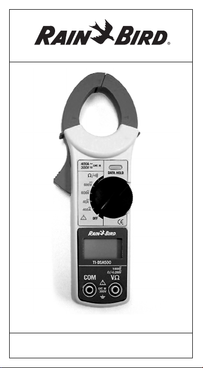
TI-DSA500 Digital Clamp Meter
TROUBLESHOOTING GUIDE
Page 2

Table of Contents
Troubleshooting Guide . . . . . . . . . . . . . . . . .3
1. Troubleshooting at the Controller
Voltage check of 120V input . . . . . . . . . . . . . . .5
Voltage check of transformer: . . . . . . . . . . . . . .6
Resistance check of fuse: . . . . . . . . . . . . . . . . .6
Voltage check of battery: . . . . . . . . . . . . . . . . . .6
Voltage check of station output: . . . . . . . . . . . . .8
2. Troubleshooting the System
Resistance check of each station: . . . . . . . . . . .9
Voltage check of each valve: . . . . . . . . . . . . . .10
Current check of station wires: . . . . . . . . . . . . .11
Voltage check of pump relay: . . . . . . . . . . . . . .12
WARNING
This booklet is only intended to be a guide for using this
product with other Rain Bird products. Carefully read and
follow the manufacturer’s instructions regarding safety
precautions and warranty information.
FOR TECHNICAL SUPPORT
800-247-3782 (USA and Canada only)
The World’s Leader in Irrigation
-2-
Page 3

Troubleshooting Guide
for Zone Irrigation Systems
This Troubleshooting Guide will assist you in the location of
fault in an irrigation control system related to power supply
or valve control wires. There are corresponding instructions
on how to use the test tool to accomplish steps that require
their use.
Step 1 Make sure the master water supply is turned on.
Step 2 Make sure any shut-off devices, such as a rain
Step 3 Turn the controller on and sequence the clock
Step 4 Make a list of all of the stations that are not
Step 5 Turn the controller off to test the resistance at
Keep in mind the water supply may be controlled
by either a manual or electric master valve.
sensor, are disabled or disconnected.
through the different stations. If nothing is working,
skip to Step 6. If some of the stations are working,
proceed to Step 4. If all of the stations are working, then you don’t have any troubleshooting to do
at the controller.
functioning properly. Measure the output voltage
for each station using a Multi-Meter (Rain Bird
Model TI-DM200, TI-DM400 or TI-DSA500) and
the instructions provided. See Page 8 of this guide.
If the power is in range at every station (24-28
VAC ), proceed to Step 5. If the power is correct
when you test some stations, but not others, you
may need to have your controller repaired. Take
your controller to an authorized distributor.
each station. Use the following table to diagnose
the problem that each station may have.
0-5 ohms Fully Shorted Solenoid
8-20 ohms Shorted Solenoid or Multiple Valves
20-60 ohms Normal
> 60 ohms Bad Connection, Splices, Nicked
Wires, Open Solenoid or Broken Wire
-3-
Page 4

Step 5 (Continued from previous page)
Step 6 Turn the controller off and remove the cover.
Step 7 Check the 120 V power being supplied to the
Step 8 Check the output of the transformer supplying
Use the instructions provided to test any valves
(or solenoids or wires) on the stations with faulty
resistance measurements (Page 9 of this guide).
A Rain Bird Tone and Probe Kit (Model TI-TPK)
or a Rain Bird Wire Sorter (Model TI-WS6) can
be helpful in locating broken wires and diagnosing
your system. The "snap-around" feature of
Rain Bird’s Model TI-DSA500 Multi-Meter allows
you to check the current of field wiring without
disconnecting it (Page 11 of this guide).
Check the fuse using a Multi-Meter (Rain Bird
Model TI-DM200, TI-DM460 or TI-DSA500) and
the instructions provided (Page 6 of this guide). If
the fuse is good, proceed to Step 7. If the fuse is
bad, replace it and start again at Step 3.
controller according to the instructions provided
(Page 5 of this guide). If the 120 V power is
in range (105-129 VAC), proceed to Step 8.
If the power is out of range, have an electrician
troubleshoot the wiring to the controller. Once
the 120 V power has been restored, start again
at Step 3.
power to your controller according to the instructions
provided with your Multi-Meter (Page 6 of this
guide). If the transformer’s power output is in
range (24-28 VAC), you may need to have your
controller repaired. If the transformer’s output is
out of range, you may have a bad transformer.
-4-
Page 5

Voltage Check of 120V Input
SET METER TO
PROBE
CONNECTIONS
For Standard Outlets:
1) Insert probes into outlet one at a time.
2) Observe voltage reading on TI-DSA500 display.
3) Remove probes from outlet
For hard wired controllers:
1) Turn power off at main circuit breaker.
2) Disconnect the wire nuts inside of the controller where
the power lines connect to the transformer.
3) Make sure the wire nuts are not touching each other
or anything else.
4) Turn power back on.
5) Touch a probe to each wire nut to check power
6) Observe voltage reading on TI-DSA500 display
7) Turn power back off,
8) Reconnect the lines inside of the controller
9) Turn power back on.
Acceptable range: 105-129V (AC)
600
BLACK
COM
V
AC
ñ
RED
V
-5-
Page 6

Voltage Check of Transformer (fig.1)
SET METER TO
PROBE
CONNECTIONS
1) Hold one probe to each of the power lines that run into
the terminal strip from the transformer. Be careful not to
touch the probes together.
2) Check the reading on your multimeter.
Acceptable range: 24-28V (AC)
600
BLACK
COM
V
AC
ñ
RED
V
Resistance Check at Fuse (fig. 2)
SET METER TO
PROBE
CONNECTIONS
1) Remove cover of controller.
2) Remove each fuse to test it.
3) Touch one probe to each side of the fuse.
4) Check the reading on your multimeter.
Acceptable range: Very low or zero (Ohms): OK.
A high value or Over-Range Indication (OL) indicates
a bad fuse.
Note: The TI-DSA500 will make a beeping noise when the
reading is below 50±35 Ω in this mode.
/
BLACK
COM
RED
V
Voltage Check at Battery (fig.3)
SET METER TO
PROBE
CONNECTIONS
1) Remove cover from the controller and remove the
DC battery.
600
BLACK
COM
V
DC
RED
V
-6-
Page 7

2) Insert black and red test leads into COM and the
VΩ terminal.
3) Place selector switch to 600V
4) Touch one probe to the metal lead on each side of
DC
.
the battery.
5) Check the reading on your multimeter.
6) Replace the battery.
CAUTION: Avoid electrical shock or instrument damage
by not exceeding 10Vdc while in battery test mode.
Acceptable battery test range: Varies by battery type
and manufacturer. A negative value only indicates that the
(+) probe is on the (-) terminal.
fig. 1
fig. 2
-7-
fig. 3
Page 8

Voltage Check of Station Output
SET METER TO
PROBE
CONNECTIONS
1) Check to see if a rain sensor or other shut-off device is
connected to the controller. If so, disable or disconnect
the sensor before performing further troubleshooting.
2) Remove cover of controller to expose terminal strip.
3) Turn controller to manual mode and activate the station
or master valve (MV) to be checked.
4) Touch (insert) one probe to the terminal labeled COM
(for common).
5) Touch the other probe to the terminal of the station
(or MV) to be checked.
6) Check the reading on your multimeter.
Acceptable range: 24-28V (AC)
600
BLACK
COM
V
AC
ñ
RED
V
-8-
Page 9

Resistance Check of Each Station
SET METER TO
PROBE
CONNECTIONS
CAUTION: TURN CONTROLLER OFF
Remove cover of controller to expose terminal strip.
1) Touch (insert) one probe to the terminal labeled
COM (for common).
2) Touch the other probe to the terminal of the station
(or MV) to be checked.
3) Check the reading on your multimeter.
Acceptable range: 20-60 Ohms
Less than 20 indicates a short or crossed wires, more
than 60 indicates a broken wire, bad splice or bad
solenoid. Note that stations with several valves will have
proportionately lower resistance. For example, a station
with two valves connected will show half the resistance.
/
BLACK
COM
RED
V
Note: The TI-DSA500 will make a beeping noise when the
reading is below 50±35 Ω in this mode.
-9-
Page 10

Voltage Check of Each Valve
SET METER TO
PROBE
CONNECTIONS
1) At the controller, turn on the station of the valve to
be tested.
2) Touch each probe to an exposed part of each of the
two splice wires leading into the solenoid. If it is easier,
disconnect the solenoid and just check the voltage drop
across the two wires coming from the controller.
3) Check the reading on your multimeter.
Acceptable range: 24-28V (AC)
To the controller
600
BLACK
COM
V
AC
ñ
RED
V
-10-
Page 11

Current Check of Station Wires
SET METER TO
PROBE
CONNECTIONS
WARNING
Do not make measurement on a circuit with a voltage
•
higher than 600 VAC. Otherwise, shock hazard or damage
to the instrument or equipment under test may result.
Transformer jaw tips are designed to minimize the possibility
•
of shorting conductors in the circuit under test. If equipment
under test has exposed conductive parts, however, extra
precaution should be taken to avoid possible shorting.
Do not make measurement with the battery compartment
•
cover removed.
Do not make current measurement with the test leads
•
connected to the instrument.
1) Set the function selector switch to 40A position.
2) Press the trigger to open the transformer jaws and clamp
around one conductor only.
3) Observe the reading on the display.
Acceptable ranges: For standard AC solenoid valves
the current will be zero for valves that are off and range
between X and XX when on.
Note:
During current measurement, keep the transformer jaws
•
fully closed. Otherwise, accurate measurement cannot be
made. The maxi-mum conductor size is 30mm in diameter.
When measuring a larger current, the transformer jaws
•
may buzz. This does not affect the instrument’s accuracy.
40A
AC
ñ
BLACK
RED
COM
V
CORRECT INCORRECT
-11-
Page 12

Voltage Check of Pump Relay
SET METER TO
PROBE
CONNECTIONS
1) At the controller, turn on the station or master valve (MV)
that controls the pump relay to be tested.
2) At the pump relay, expose a part of each of the two wires
coming out of the relay.
3) Touch a probe to each of the exposed wires.
4) Check the reading on your multimeter.
Acceptable range: 24-28 V (AC)
Rain Bird Corporation
970 West Sierra Madre Avenue
Azusa, CA 91702
www.rainbird.com
600
BLACK
COM
V
AC
ñ
RED
V
-12-
 Loading...