

Page 1

MAXI® Interface Module
(Model MIM)
and Interface Expansion Module
(Model MIM-X)
Installation and Operating
Instructions Manual
Read these instructions completely
before installing or operating this unit.
P/N 630775-A
GT27042A
11/30/90 Cozz
Page 2

FIGURES
FIGURE PAGE
Figure #1: Cabinet Mounting Holes 2
Figure #2: Interface Module 3
Figure #3: Cabinet Front Panel 4
Figure #4: Interface Module to Computer 5
Figure #5: Surge Arrestor on Electrical Panel 5
Figure #6: 2-Wire Path & Grounding Terminal Strip 6
Figure #7: Grounding of Interface Module/2-Wire Paths Surge Protection 7
Figure #8: 2-Wire Path Power & Signal Indicating Lights 8
Figure #9: Expansion Module 9
Figure #10: 2-Wire Path & Grounding Terminal Strip for Expansion Module 10
Figure #11: 2-Wire Path Power & Signal Indicating Lights 11
Figure #12: Front Panel Assembly 12
Figure #13: Group or 2-Wire Path Activity Lights 13
Figure #14: Memory Switch 14
Figure #15: Channel/Station Switch 15
Figure #16: Channel Activity Lights 16
Figure #17: Station Activity Lights 18
Figure #18: Output Circuit Breakers 19
Figure #19: Mode Switch 20
Figure #20: Group Window 21
Figure #21: Channel Window 22
Figure #22: Start/Advance & Cancel Switches 23
Figure #23: Test Switch 24
Figure #24: Status Switch 25
Figure #25: Expansion Module Front Panel 26
Figure #26: Output Circuit Breakers 27
I
Page 3

CONTENTS
DESCRIPTION PAGE
INTRODUCTION 1
INSTALLATION 2
Interface Module (MIM) 2
Expansion Module (MIM-X) 9
OPERATIONS 12
MAXI® Interface Module (Model MIM)
Module Function 12
Front Panel Familiarization 12
Group Activities Lights 13
Memory Switch 14
Channel/Station switch 15
Channel Activity Lights 16
Station Activity Lights 17
Output Circuit Breakers 19
Mode of Operation Switch 19
Group Window & Up/Down Buttons 21
Channel Windows & Up/Down Buttons 22
Manual Operation of a Satellite 23
Test Switch 24
Status Lights 25
Summary 26
Interface Expansion Module (Model MIM-X)
Expansion Module Function 26
Front Panel Familiarization 26
Output Circuit Breakers 27
Summary 27
II
Page 4

FCC. REQUIREMENTS:
NOTE:
THIS EQUIPMENT HAS BEEN TESTED AND FOUND TO COMPLY WITH THE LIMITS FOR A CLASS
A DIGITAL DEVICE, PURSUANT TO PART 15 OR THE FCC RULES. THESE LIMITS ARE DESIGNED
TO PROVIDE REASONABLE PROTECTION AGAINST HARMFUL INTERFERENCE WHEN THE
EQUIPMENT IS OPERATED IN A COMMERCIAL ENVIRONMENT. THIS EQUIPMENT GENERATES,
USES, AND CAN RADIATE RADIO FREQUENCY ENERGY AND, IF NOT INSTALLED AND USED IN
ACCORDANCE WITH THE INSTRUCTION MANUAL, MAY CAUSE HARMFUL INTERFERENCE TO
RADIO COMMUNICATIONS. OPERATION OF THIS EQUIPMENT IN A RESIDENTIAL AREA IS LIKELY
TO CAUSE HARMFUL INTERFERENCE IN WHICH CASE THE USER WILL BE REQUIRED TO CORRECT
THE INTERFERENCE AT HIS OWN EXPENSE.
III
Page 5

INTRODUCTION
The MAXI® Interface Module Unit is used to pass the information, received from the
Computer, on to the field Stand-By Modules (Satellite Units). In a like manner it also passes
“Feed-Back” information, from the Field Satellite units back to the Computer. In so doing, it also
displays a certain amount of information for viewing by the operator.
The MAXI Interface Module is capable of communicating with FOUR (4) different wire
paths at one time. Each wire path is capable of communicating to a maximum of TWENTY
EIGHT (28) Field Satellites or Decoder Devices.
The MAXI Interface Expansion Module provides for the capability of FOUR (4) additional
wire paths for a Total of EIGHT (8) wire paths on the system. Each wire path on the Expansion
Module is also capable of communicating to a maximum of TWENTY EIGHT (28) Field Satellites
or Decoder Devices.
All information for any Group Activity, Channel Activity and Station Activity is displayed on
the MAXI Interface Module - even when both the MIM Interface Unit and the MIM-X Expansion
Unit are used.
A MEMORY Switch provides for the preserving of status information or operational
information for viewing at some future time.
Full MANUAL Operation of any Satellite, on the system, may be performed from the
Interface Module.
Status lights indicate when the system is in proper operating condition and when
communication with the MAXI computer is occurring.
1
Page 6
INSTALLATION
INTERFACE MODULE
STEP #1:
Remove the unit from the carton. Be sure you do not lose the power cord.
STEP #2:
Determine a suitable wall mounting location for the unit near the central computer. Unit
dimensions are: 15 1/2" W x 12 1/2" H x 6" D. The unit should be mounted at EYE-LEVEL for easy
observation and operation.
When using an Expansion Module (MIM-X) you will need space for this unit beside the basic
Interface Module (MIM) and to the right of the Interface Module. Leave at least 6 inches
between the two units. Unit Dimensions and mounting of the Expansion Module are exactly
the same as for the basic Interface Module.
STEP #3 :
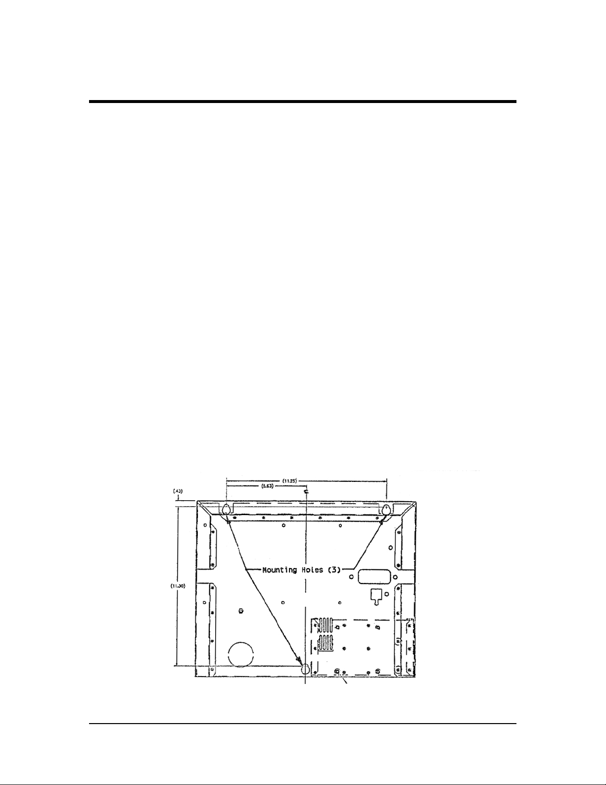
Using 3 large flat head, #6 screws, 1/2" to 3/4" long or other suitable screws, bolts, etc, as
the wall material may dictate. Locate the screws on the wall of the mounting location in the
geometric pattern as shown in FIGURE #1.
FIGURE #1: CABINET MOUNTING HOLES
2
Page 7
TIP: Do not install screws full depth. Leave the head of the screws 1/8"
from the wall, to allow cabinet to slip over it. Then tighten the
screws, once the cabinet is in place.
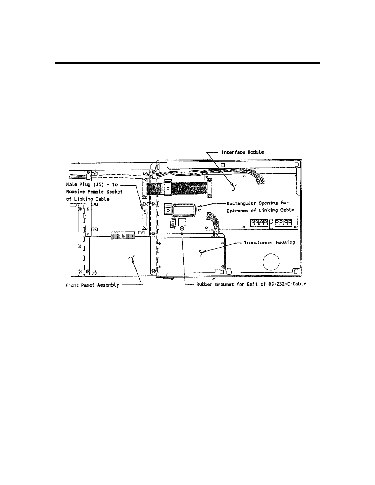
If an EXPANSION Module is being used: Bring the 25-Pin female connector, of the linking cable
packaged with the Expansion Module, in through the back of the INTERFACE Module, through
the rectangular opening above the transformer housing. Refer to FIGURE #2.
FIGURE #2: INTERFACE MODULE
Plug the connector on to the MALE PLUG (J4) on the PC Board, that is mounted on the back
side of the Front Panel Assembly, of the Interface Module. To do this you will have to “OPEN”
the Front Panel, as outlined under STEP #4 below. The Cable shall feed to the right side of the
INTERFACE Module and lay in the channel provided for it In the back of the cabinet.
Slip the unit over the screw heads and then seat firmly “DOWN” onto the screws.
STEP #4:
Open the Front Panel of the Interface Module.
Loosen the screw in the UPPER RIGHT HAND corner of the front panel. Also loosen the two
screws at the CENTER and RIGHT HAND corner, on the BOTTOM of the front panel. DO NOT
loosen the CENTER screw on the Right Hand Side of the front panel. Refer to FIGURE #3.
3
Page 8
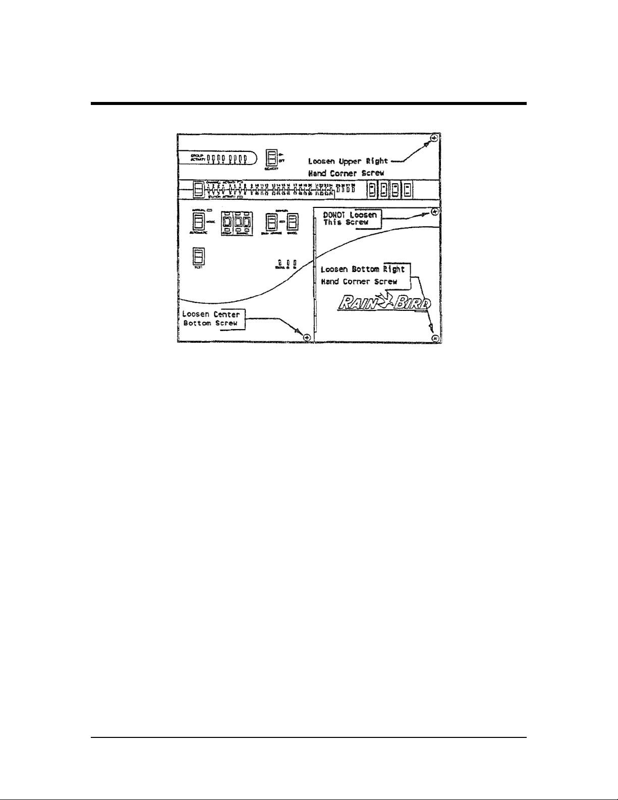
FIGURE #3: CABINET FRONT PANEL
TIP: The screws are “Captured” so they only need to be loosened and
NOT taken completely out.
STEP #5:
Open the Front Panel of the INTERFACE Module and swing it to the LEFT. Be sure the RS232-C phone type cable is extended out the Grommeted Hole in the back of the cabinet and
cown from the bottom of the Interface Module. Also be sure that the LINKING CABLE for the
Expansion Module, is properly located as instructed above, in STEP #4.
Now TIGHTEN the three screws to secure the unit to the wall.
STEP #6:
Close the Front Panel and secure the UPPER RIGHT-HAND corner screw and the BOTTOM
CENTER screw, DO NOT secure the BOTTOM RIGHT-HAND screw. Refer to FIGURE #3, above.
STEP #7:
Connect the RS-232-C cable to the Serial Port output of the computer, using the Adapter plug
at the computer. Refer to FIGURE #4.
4
Page 9
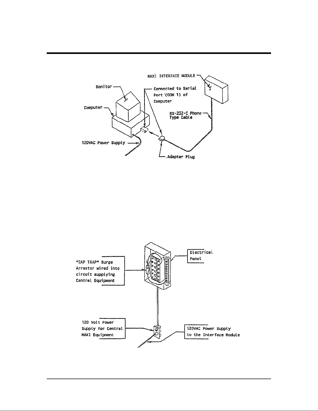
FIGURE #4: INTERFACE MODULE TO COMPUTER
STEP #8:
Connect the 120 Volt Power Cord to the Plug on the Bottom Left Back Corner of the unit.
Plug the cord into a suitable 120 Volt grounded duplex outlet (the circuit supplying this unit
and the computer equipment should be protected by a “ZAP TRAP” Surge Arrestor Dev Refer
to FIGURE #5.
FIGURE #5: SURGE ARRESTOR ON 120VAC CIRCUIT AT ELECTRICAL PANEL
5
Page 10

STEP #9:
Loosen the MIDDLE screw on the RIGHT-HAND SIDE of the Front Panel. Refer to FIGURE #3.
Open the SMALL Access door, by swinging it to the left.
STEP #10:
CAUTION ! BE SURE THE OUTPUT CIRCUIT BREAKERS, ON THE FRONT
PANEL ARE IN THE “OFF” POSITION.
Connect the various 2-Wire Paths of the system to the Proper Terminals on the Terminal Block.
Refer to FIGURE #6.
FIGURE #6: 2-WIRE PATH & GROUNDING TERMINAL STRIP
Wires may be run in conduit, which can be connected to the bottom of the unit at the 1 1/2"
conduit “knock-out”.
DOUBLE CHECK... Be sure the RED wire, of each 2-Wire Path is to the or terminal and the
BLACK wire is to the “COM” terminal for EACH Wire Path.
NOTE: When the MIM unit is installed as a replacement for an MTW
unit - any END-OF-LINE TERMINATORS on the 2-Wire paths
MUST BE REMOVED.
6
Page 11

STEP 11
As close to the Central location as possible, install a 3-Rod Earth Grounding Grid. It shall,
consist of three (3) 5/8' Diameter x 8' - 0" Long copper clad grounding rods -driven at least 8' 0" apart in a triangular pattern. Connect the Rods together, below ground, with a #10 or Larger
Bare Copper Grounding Conductor and using Brass Clamps to attach it to the Rods.
Connect a #10 or larger copper grounding conductor to the GROUND LUG on the Terminal
Strip (Refer to FIGURE #6, above). Connect the other end to the Ground Rod, of the 3-Rod
Grounding Grid, that is closest to the unit - using a brass ground clamp. Refer to FIGURE #7.
FIGURE #7: GROUNDING OF INTERFACE MODULE 2-WIRE PATHS SURGE PROTECTION
7
Page 12

For each two (2) - 2-Wire Path, install on the earth grounding rod, that is closest to the Central,
an MGP-1 Grounding Plate Assembly, securely clamped to the rod by means of the clamp and
bolts on it. Mount on it an MSP-1 Surge Arrestor for EACH of the 2-Wire Paths. Ground each
end of the MSP-1 to the MGP-1 Grounding Plate Assembly by means of the grounding screws
on the plate. Connect each MSP-1 Surge Arrestor into one of the 2-Wire Paths.
Install a standard rectangular valve box, to house the MSP-1 Surge Arrestors and the MGP-1
Grounding Plate Assemblies in order to provide easy access to these units for future inspection
and/or maintenance. Refer to FIGURE #7.
STEP #12:
Place the OUTPUT Circuit Breakers to the “ON” position. Observe that the RED indicating LED’s,
on the PC Board just above the terminal strip are “BLINKING”, thus indicating that the line is
powered and the signal is being sent out to the field. Refer to FIGURE #8.
FIGURE #8: 2-WIRE PATH POWER & SIGNAL INDICATING LIGHTS
Close the access door and secure it with the two screws, on the right hand side of the Front
Panel.
THE INSTALLATION OF THE UNIT HAS NOW BEEN COMPLETED.
8
Page 13

EXPANSION MODULE (OPTIONAL)
ONLY IF USED ON THE SYSTEM
STEP #14:
Bring the 25-Pin MALE Connector of the LINKING cable in through the back of the EXPANSION
Module, through the rectangular opening above the transformer housing. Plug the connector
into the FEMALE Socket (J1), on the PC Board mounted on the back panel of the EXPANSION
Module. This requires that the Front Panel be “OPENED”. Follow the procedure as outlined
above, in Step #4 for the Interface Module. Refer to FIGURE #9.
FIGURE #9: EXPANSION MODULE
Route the Linking Cable to the LEFT Side of the Expansion Module, using the Slot (Channel)
provided for it in the back of the cabinet.
Slip the unit over the screw heads and then seat firmly “DOWN” onto the screws.
STEP #15:
Now tighten the three (3) screws to secure the unit to the wall.
9
Page 14

STEP #16:
Close the Front Panel and secure the Upper RIGHT Comer Screw and the Lower CENTER Screw.
DO NOT secure the Lower RIGHT Corner Screw.
STEP #17:
Connect the 120 Volt Power cord to the plug on the Bottom LEFT Back Corner of the unit
cabinet. Plug the cord into a suitable 120 Volt grounded Duplex outlet (the Circuit supplying
power to this unit and the other central equipment should be protected by a “ZAP TRAP” Surge
Arrestor device). Refer to FIGURE #5.
STEP #18:
Loosen the MIDDLE Screw, on the RIGHT Hand side of the Front Panel. Open the SMALL Access
Door, by swinging it to the LEFT.
STEP #19:
CAUTION ! BE SURE THE OUTPUT CIRCUIT BREAKERS ON THE FRONT
PANEL ARE IN THE “OFF” POSITION.
Connect the various 2-Wire Paths (Wire Paths #5, #6, #7 and #8) of the system to the proper
terminals on the terminal block. Refer to FIGURE #10.
FIGURE 10: 2-WIRE PATH & GROUNDING TERMINAL STRIP FOR EXPANSION MODULE
10
Page 15

Wires may be run in conduit, which can be connected to the bottom of the unit at the 1 1/2"
conduit “knock-out”.
DOUBLE CHECK... Be sure the RED wire, of each 2-Wire Path is to the “HOT” terminal and the
BLACK wire is to the COM terminal for EACH Wire Path.
STEP #20:
Connect a #10 or larger copper grounding conductor to the GROUND LUG on the Terminal
Strip (Refer to FIGURE #10). Connect the other end to the Ground Rod, of the 3-Rod Grounding
Grid, that Is closest to the unit - using a brass clamp or MGP-1 Grounding Plate Assembly. Refer
to FIGURE #7: Grounding of Interface Module. The EXPANSION Module will connect in a similar
manner.
For each two (2) - 2-Wire Path, install on the earth grounding rod, that is closest to the Central,
an MGP-1 Grounding Plate Assembly, securely clamped to the rod by means of the clamp and
bolts on it. Mount on it an MSP-1 Surge Arrestor for EACH of the 2-Wire Paths. Ground each
end of the MSP-1 to the MGP-1 Grounding Plate Assembly by means of the grounding screws
on the plate. Connect each MSP-1 Surge Arrestor into one of the 2-Wire Paths.
STEP #21:
Place the OUTPUT Circuit Breakers to the “ON” position. Observe that the RED indicating LED’s,
on the PC Board just above the terminal strip are “BLINKING”, thus indicating that the line is
powered and the signal is being sent out to the field. Refer to FIGURE #11:
FIGURE #11: 2-WIRE PATH POWER
& SIGNAL INDICATING LIGHTS
Close the access door and secure it with the two screws on the right hand side of the Front Panel.
THE INSTALLATION OF THE UNIT HAS NOW BEEN COMPLETED.
11
Page 16

OPERATIONS
MAXI® INTERFACE MODULE (MODEL MIM)
MODULE FUNCTION:
The MAXI Interface Module function is to take the signal from the computer Serial Output
Port and transform it to a signal to be transmitted to the Field Stand-by Modules. Through this
communication transmission, over the various 2-Wire Paths, the Field Stand-by Modules (or
Satellite units) are instructed “WHEN” to operate and what “STATION” to operate.
In addition the MAXI Interface Module also receives, via the 2-Wire Path, “Feed-Back”
information from the Field Satellite Units. This “Feed-Back” information is passed on to the
Computer. In addition the MAXI Interface Module also displays some of this information,
directly to the user via various LED’s located on its front panel.
A third function of the MAXI Interface Module Is to provide a means of MANUAL Operation, of
the Field Stand-by Modules, directly from it. In so doing “Feed-Back” information will also be
received and displayed by the Interface Module Unit.
The MAXI Interface Module is also capable of displaying and conveying a certain amount of
”self-testing” and “trouble shooting” status data to the user.
FRONT PANEL FAMILIARIZATION:
Let us first take a look at the Front Panel to familiarize the user with its components and
benefits.
FIGURE #12: FRONT PANEL ASSEMBLY
12
Page 17

GROUP ACTIVITIES LIGHTS:
PURPOSE...
To provide indication of activity or satellite operation on the 2-Wire Path.
OPERATION...
There are eight (8) GROUP ACTIVITY (or 2-Wire Path) lights located in the upper left hand
corner of the front panel, (Refer to FIGURE #13 - Group or Wire Path Activity Lights).
FIGURE #13: GROUP OR 2-WIRE PATH ACTIVITY LIGHTS
You will note that there is a light for each of the eight (8) 2-Wire Paths possible on a system.
When any of the up to 28 devices in a group are addressed and respond with a feedback
condition of “ON”, the corresponding GROUP ACTIVITY light will turn “ON”.
SATELLITE FAILURE TO RESPOND...
Should a satellite unit or a number of satellite units, fall to respond when they are being
addressed, the activity light for that 2-Wire Path will continue to “BLINK” for as long as they
fail to respond. Even if all other satellites have returned to their “REST” position, this indicating
light will continue to “BLINK”. Thus you have a visual indication that a satellite or a number of
satellites have tailed to operate and you have some type problem.
13
Page 18

MEMORY SWITCH:
PURPOSE...
To provide a visual indication of “PAST” Activity on the various 2-Wire Paths.
OPERATION...
To the immediate RIGHT of the GROUP ACTIVITY LIGHTS is a two-position Rocker Type
MEMORY Switch, having an “ON” and an “OFF” position. (Refer to FIGURE #14 - Memory Switch).
FIGURE 14: MEMORY SWITCH
With the MEMORY Switch in the “OFF” POSITION the GROUP Activity LIGHTS will function as
described under “GROUP ACTIVITY LIGHTS” - immediately proceeding this section.
With the MEMORY Switch in the “ON” position - once activity has taken place on any of the
2-Wire Paths - the GROUP ACTIVITY LIGHT will REMAIN lighted. This will occur even though all
satellites have finished operation and have returned to their “REST” position. Thus you have a
visual indication that activity has taken place some time prior to the present time. To “RESET”
the activity lights - place the MEMORY Switch in the “OFF” position and then switch back to
“ON”, if desired. The LIGHTS will now be reset.
CAUTION ! Before doing so, however, be sure you have checked all other
status information, that you desire to observe, as this
information will also be “RESET”.
14
Page 19

CHANNEL/STATION SWITCH:
PURPOSE...
To provide selection of either the CHANNEL ACTIVITY LIGHTS or the STATION ACTIVITY LIGHTS.
OPERATION...
Just below the Group Activity Lights is a two-position Rocker Type CHANNEL/STATION Switch.
(Refer to FIGURE #15 - Channel/Station Switch).
FIGURE #15: CHANNEL/STATION SWITCH
This Switch, when in the “UP” position, selects the display lights to indicate CHANNEL ACTIVITY.
When the Switch is in the “DOWN” position it selects the display lights to indicate the STATION
ACTIVITY.
15
Page 20

CHANNEL ACTIVITY LIGHTS:
PURPOSE...
To provide an indication of CHANNEL Activity or satellite operation, on a given 2-Wire Path.
OPERATION...
Just to the RIGHT, of the TOP, of the CHANNEL/STATION Switch and just after the Channel
Activity designation is an indicating light. When the Channel/Station Switch is in the “UP”
position - this indicating light will be lighted - indicating that the activity lights are now set to
display CHANNEL Activity or SATELLITE Activity on a given 2-Wire Path.
Just to the RIGHT, of the CENTER, of the Channel/Station Switch are twenty eight (28)
CHANNEL Activity LIGHTS - one for each of the twenty eight (28) individual channels available
on a given 2-Wire Path. (Refer to FIGURE #16 -Channel Activity Lights).
FIGURE #16: CHANNEL ACTIVITY LIGHTS
With the MEMORY Switch in the “OFF” position, EACH of these CHANNEL ACTIVITY LIGHTS will
indicate when a given channel or satellite, on a particular wire path, is in operation.
16
Page 21

Operation may be initiated in any of the following ways:
a) By a program from the computer.
b) Manually from the Interface Module.
c) Manually from the Satellite in the Field.
SATELLITE FAILURE TO RESPOND...
With the MEMORY Switch in the “OFF” position - any satellite falling to respond, when it has
been addressed, will be indicated by its CHANNEL ACTIVITY LIGHT > “BLINKING”.
With the MEMORY Switch in the “ON” position - once a satellite has responded, even though it
may now be at its “REST” position, the CHANNEL ACTIVITY LIGHT for it will REMAIN LIGHTED.
Thus you have a visual indication that activity, by that satellite has taken place some time prior
to the present time. To “RESET” the CHANNEL ACTIVITY LIGHTS place the MEMORY Switch to
the “OFF” position and then back to “ON”, if desired.
CAUTION ! Before so doing, however, be sure you have checked all other
status information, that you desire to observe, as this
information will also be “RESET”.
STATION ACTIVITY LIGHTS:
PURPOSE...
To provide an indication of STATION ACTIVITY on a given satellite that is in operation at the
time.
OPERATION...
Just to the RIGHT, of the BOTTOM, of the Channel/Station Switch and just after the Station
Activity designation is an indicating light When the Channel/Station Switch is in the “DOWN”
position - this indicating light will be lighted - indicating that the Activity lights are now set to
display SATELLITE STATION Activity for any satellite in operation at the present time.
Just to the RIGHT, of the CENTER, of the Channel/Station Switch are twenty four (24) STATION
ACTIVITY LIGHTS - one for each of the 12 or 24 stations available on a field satellite. (These
are the SAME indicating lights that are used to indicate Channel Activity, as described in the
preceding section). Refer to FIGURE #17 - Station Activity Lights.
17
Page 22
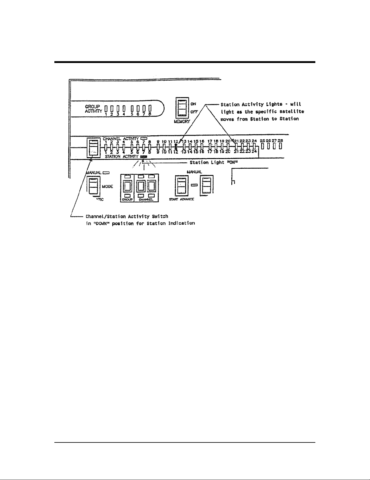
FIGURE #17: STATION ACTIVITY LIGHTS
With the MEMORY Switch in the “OFF” position STATION ACTIVITY LIGHTS will indicate which
station, of a given satellite is in operation, when the satellite has been started either by a
program in the Computer or started Manually from the Interface Module.
NOTE ! If the satellite has been started or is being operated manually
at the satellite in the field, there will be NO STATION
INDICATION.
STATION FAILURE TO RESPOND...
With the MEMORY Switch in the “OFF” position - any station of a given satellite, tailing to
respond, when it is being addressed, will be indicated by the STATION ACTIVITY LIGHT for that
station “BLINKING”.
With the MEMORY Switch in the “ON” position - once the satellite has “stopped” on a station,
even though it may now be on some other station or at the “REST” position, the STATION
ACTIVITY LIGHT, for that station will REMAIN LIGHTED. Thus you have visual indication of each
station that has operated. To “RESET” the STATION ACTIVITY LIGHTS place the MEMORY Switch
In the “OFF” position and then back to “ON”, if desired.
CAUTION ! Before so doing, however, be sure you have checked all other
status information, that you desire to observe, as this
information will also be “RESET”.
18
Page 23

OUTPUT CIRCUIT BREAKERS:
PURPOSE...
To prevent damage to the Interface Module from shorts on the 2-Wire Path.
OPERATION...
Just to the RIGHT of the CHANNEL/STATION ACTIVITY LIGHTS are four (4) Rocker Switch type
OUTPUT CIRCUIT BREAKERS - one for each of the possible four (4) 2-Wire Paths on the MAXI®
Interface Module. (Refer to FIGURE #18 -Output Circuit Breakers).
FIGURE #18: OUTPUT CIRCUIT BREAKERS
With the OUTPUT CIRCUIT BREAKER Switch in the “ON” position, the 2-Wire Path is connected
electrically to the Interface Module and communication to the field, over this 2-Wire Path can
take place. With the OUTPUT CIRCUIT BREAKER Switch in the “OFF” position, the 2-Wire Path is
electrically DISCONNECTED from the Interface Module and NO communication can take place
over this 2-Wire Path.
MODE OF OPERATION SWITCH
PURPOSE...
Provides the means for “MANUAL” operation of the satellites from the Interface Module or for
“AUTOMATIC” operation of the satellites from the Computer.
19
Page 24

OPERATION...
Just below the CHANNEL/STATION Switch is the two (2) position rocker type MODE of
OPERATION Switch. (Refer to FIGURE #19 - Mode Switch).
FIGURE #19: MODE SWITCH
With this switch in the “UP” or “MANUAL” POSITION the light to the RIGHT of the word MANUAL
will be lighted - indicating that the INTERFACE MODULE is now to be operated MANUALLY
and NOT from the Computer. With the switch in this position, Field Satellite units can ONLY
be operated MANUALLY from the interface Module or from the Field Satellite unit itself. Field
Satellites CAN NOT be Automatically operated from the Computer. The MANUAL indicating
LIGHT will ALWAYS be lighted to give you visual indication that the system Is in the MANUAL
MODE of operation.
With the MODE of OPERATION Switch in the “DOWN” or “AUTOMATIC” position - Field Satellite
units may be operated Automatically from programs in the computer or manually operated
from the field satellite unit itself. The indicating Light, to the RIGHT of the word MANUAL will
be “OFF”, when the MODE of OPERATION Switch is in the “AUTOMATIC” position.
With the MODE Switch in either the MANUAL or AUTOMATIC position, the GROUP ACTIVITY
LIGHTS, the CHANNEL ACTIVITY LIGHTS and/or the STATION ACTIVITY LIGHTS will function as
previously described.
20
Page 25
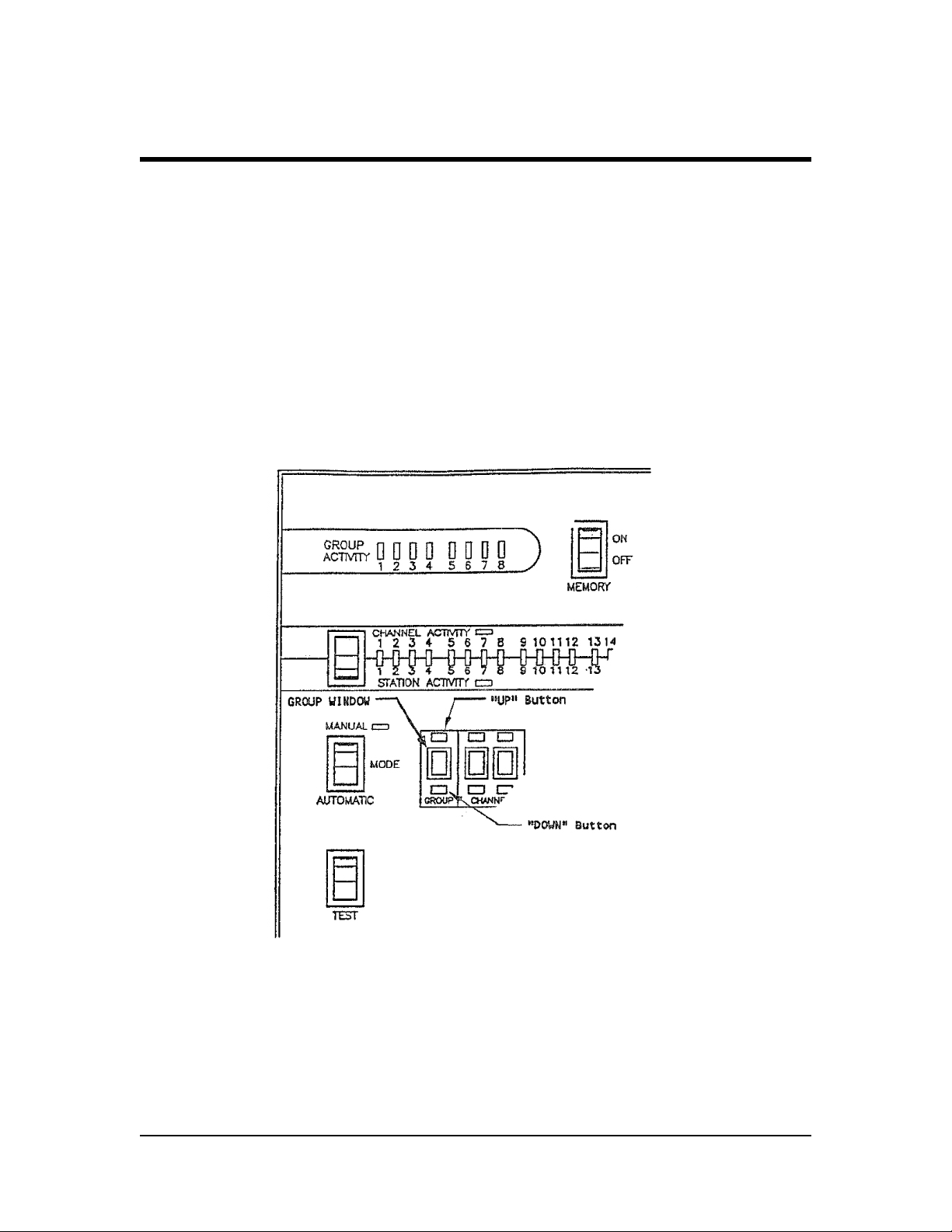
GROUP WINDOW & UP/DOWN BUTTONS:
PURPOSE...
Provides the means for identifying the Group Number or 2-Wire Path number for both the
CHANNEL Activity LIGHTS and the STATION ACTIVITY LIGHTS and for MANUALLY “STARTING” or
“ADVANCING” a given Field Satellite on that wire path.
OPERATION...
Located just to the RIGHT of the MODE Switch is the GROUP WINDOW with “UP” button above
the window and “DOWN” button below the window. (Refer to FIGURE #20 - Group Window).
FIGURE #20: GROUP WINDOW
By use of the “UP”/”DOWN buttons you can identify, in the window, which of the GROUPS or
2-Wire Paths you wish to observe or manually operate. The CHANNEL ACTIVITY and STATION
ACTIVITY LIGHTS will then correspond to this GROUP or 2-Wire Path NUMBER displayed in the
GROUP WINDOW.
21
Page 26

CHANNEL WINDOWS & UP/DOWN BUTTONS:
PURPOSE...
Provides the means of identifying the Channel Number or Satellite Number, on the previously
identified Group or 2-Wire Path for the STATION ACTIVITY LIGHTS or of the satellite you wish to
MANUALLY operate.
OPERATION...
Located just to the RIGHT of the GROUP WINDOW are the two (2) CHANNEL WINDOWS with an
“UP” button above each window and a “DOWN” button below each window. (Refer to FIGURE
#21 CHANNEL Windows).
FIGURE #21: CHANNEL WINDOWS
By use of the “UP/”DOWN’ buttons you can identity, in the windows, which of the channels on
the previously identified 2-Wire Path, you wish to observe or MANUALLY operate. The STATION
ACTIVITY LIGHTS will then display information for the Satellite identified in the CHANNEL
WINDOWS and on the 2-Wire Path identified in the GROUP WINDOW.
22
Page 27

MANUAL OPERATION OF A SATELLITE:
PURPOSE...
Provides the means of MANUAL OPERATION for any Satellite on the system, directly from the
Interface Module. My Satellite may be manually “STARTED”, “ADVANCED” or “CANCELLED” from
the Interface Module.
OPERATION....
Just to the RIGHT of the CHANNEL WINDOWS are two (2) momentary contact, rocker type
switches used for MANUAL OPERATION of a satellite. The LEFT Switch is the “START/ADVANCE”
switch and the RIGHT Switch is the “CANCEL” Switch. (Refer to FIGURE #22 - Start/Advance &
Cancel Switches.)
FIGURE #22: START/ADVANCE & CANCEL SWITCHES
An indicating light, located between the two switches will be lighted, whenever MANUAL
OPERATION is taking place. If the START/ADVANCE Switch is “PUSHED”, when the MODE Switch
is in the MANUAL position - the Satellite, whose Channel Number is identified in the CHANNEL
WINDOWS and that is on the 2-Wire Path identified in the GROUP WINDOW will “START” or if
already in operation - will “ADVANCE” to the next station.
23
Page 28

If the “CANCEL” Switch is “PUSHED” - when the MODE Switch is In the MANUAL position - the
Satellite, whose Channel Number is identified in the CHANNEL WINDOWS and that is on the
2-Wire Path identified in the GROUP WINDOW - will be “CANCELLED” and will return to its
“REST” position.
TEST SWITCH:
PURPOSE...
On the LEFT side of the panel and just below the MODE Switch is a momentary contact, rocker
type, TEST Switch. (Refer to FIGURE #23 - Test Switch).
TEST FIGURE #23: TEST SWITCH
When this Switch is activated it AUTOMATICALLY TESTS the Interface Module - exercising
all the indicating lights, etc. This provides a visual indication that the Module is in operating
condition. The process will take a minute or so to be completed.
24
Page 29

STATUS LIGHTS:
PURPOSE...
To provide some indication that communication to the field is taking place and/or that “FEEDBACK” information is being received from the field.
OPERATION...
Located to the RIGHT of the TEST Switch, there are three (3) STATUS INDICATING LIGHTS. (Refer
to FIGURE #24 -Status Lights).
FIGURE #24: STATUS LIGHTS
The light on the LEFT is the STATUS INDICTING LIGHT. When it is “BLINKING”, it indicates that
the Interface Module is functioning properly. If the indicating light burns “STEADY” it indicates
that the MIM is powered but IS NOT functioning properly.
The “RD” STATUS LIGHT will be lighted any time that there is “Feed-Back” information coming
from the field to the Interface Module, (“RD” stands for RECEIVE DATA).
The “SD” STATUS LIGHT will be lighted any time that the Interface Module is “SENDING”
information to the field. (‘SD” stands for SEND DATA).
25
Page 30

SUMMARY:
It is advisable to become thoroughly familiar with the front panel of this INTERFACE MODULE,
by studying the various switches and indicating lights, what their function and purpose is and
then by actual use experience what information and functions are provided the user. You will
find there is an abundant amount of useful information available that you will find valuable In
your every day operation of the system.
INTERFACE EXPANSION MODULE (MODEL MIM-X)
EXPANSION MODULE FUNCTION:
The MAXI® INTERFACE EXPANSION MODULE function is to add four (4) additional 2-Wire Paths
capabilities to the basic Interface Module. Thus the system can have a total of EIGHT (8) 2-Wire
Paths. The Interface Module provides Wire Paths Numbers 1, 2, 3 & 4. The Interface Expansion
Module provides Wire Paths Numbers 5, 6, 7 & 8. All “Feed-Back” information, for ALL of the
Wire Paths is displayed on the INTERFACE MODULE.
FRONT PANEL FAMILIARIZATION:
If you look at the Front Panel of the INTERFACE EXPANSION MODULE you will notice that it is
“blank”, except for the OUTPUT CIRCUIT BREAKERS. As mentioned above - ALL “Feed-Back”
information, for ALL WIRE PATHS is displayed at the INTERFACE MODULE and none is displayed
at the INTERFACE EXPANSION MODULE. (Refer to FIGURE #25 - EXPANSION MODULE).
FIGURE #25: EXPANSION MODULE FRONT PANEL
26
Page 31

OUTPUT CIRCUIT BREAKERS:
PURPOSE...
To prevent damage to the Expansion Module from shorts on the 2-Wire Path.
OPERATION...
Located on the RIGHT side of the Front Panel and just above the small wiring access door, are
four (4) rocker, switch type, CIRCUIT BREAKERS, one for each of the 2-Wire Paths possible from
this unit. (Refer to FIGURE #26 - Output Circuit Breakers).
FIGURE #26: OUTPUT CIRCUIT BREAKERS
With the CIRCUIT BREAKER Switch in the “ON” position - the 2-Wire Path is connected
electrically to the EXPANSION MODULE and communication to the field can take place.
With the CIRCUIT BREAKER Switch in the “OFF” position the 2-Wire Path is electrically
DISCONNECTED from the EXPANSION MODULE.
SUMMARY:
Except for the four (4) CIRCUIT BREAKERS mentioned above the remainder of the Front Panel
on the INTERFACE EXPANSION MODULE is “BLANK’”. ALL display and “Feed-Back” information
is given on the INTERFACE MODULE. Refer to the INSTALLATION portion of this manual for
connection of the INTERFACE EXPANSION MODULE to the INTERFACE MODULE and connection
of 2-Wire Paths.
27
Page 32

Controls Mfg. Division
Declaration of Conformity
Application of Council Directives: 89/336/EEC - 73/23/EEC
Standards To Which EN55022, Class A AS/NZS3548
Conformity Is Declared EN50081-1
EN50082-1: 1998
EN60335-1: 1995 Safety of household
and similar electrical appliances
Manufacturer: Rain Bird Corporation
Controls Mfg. Division - USA 7590
Britannia Court, San Diego, CA 92154
(619) 661-4400
Importers: Rain Bird Europe, S.A.R.L. France
BP72000
13792 Aix-en-Provence Cedex 3
(33) 442 24 44 61
Rain Bird Australia Pty Ltd.
ACN 004 644 446 P.O. Box 11
Harrisville QId. 4307
Equipment Description: Irrigation Controller
Equipment Class: Generic-Res, Comm, L.I.
Model Number: MIM
I the undersigned, hereby declare that the equipment specified above, conforms to
the above Directive(s) and Standard(s).
Tijuana B. C., Mexico
Place
Signature
John Rafael Zwick
Full Name
General Manager
Position
 Loading...