

Page 1
Auto Configure
Master Valves
Sensors
FloManager
FloWatch
Edit Configuration and Stations...
Direct Satelitte Tasks
Select One or More Sites...
Site Name Out of Sync Satellite Changes Alarm Satellites Off
Auto Contacts...
Add Site...
Synchronize
Edit Site...
Retrieve Logs...
Site Name Description
Time Zone
Postal Code
(UTC-8:00) PacificTime (US and Canada)
Site 01
OK Cancel
Satellites
Program...
Dry Run...
Manual Operations...
Configure...
Add...
Auto Configure
Master Valves
Sensors
FloManager
FloWatch
Edit Configuration and Stations...
Direct Satelitte Tasks
Client Satellite
LXME
Client Satellite
Server Satellite
2
0 gal/min
1
1
Satellite Name:
Type:
ConnectionType:
Server:
NetworkAddress:
Description:
Dry Run Warning for Max Flow:
Max. Satellite Irrigation SimulStations:
Max. Satellite Non-Irrigation SimulStations:
PIN-Codes:
Weather Source:
Configuration Stations
OK Cancel
Unprotected
Detect Modules automatically and update IQ
Upload Satelitte Configuration into IQ
Upload Satelitte Programming into IQ
Retrieve Learned Flow Data into IQ
OK Cancel
Modules
Configuration
Programs
Learned Flow
1. Choose Satellite 2. Choose IQNet Type
LXD Direct
LXME
Server
Choose the IQNet Server for this Client:
Server Satellite
LXMEF
LXM
Client
OK Cancel
Auto Configure
Master Valves
Sensors
FloManager
FloWatch
Edit Configuration and Stations...
Direct Satelitte Tasks
Satellite 001
LXME
IPConnection
10.84.177.16
5005
0 gal/min
1
1
Satellite Name:
Type:
ConnectionType:
Phone Number / IPAddress
Port:
Description:
Dry Run Warning for Max Flow:
Max. Satellite Irrigation SimulStations:
Max. Satellite Non-Irrigation SimulStations:
PIN-Codes:
Weather Source:
Configuration Stations
OK Cancel
Unprotected
Satellites
Program...
Dry Run...
Manual Operations...
Configure...
Add...
1. Choose Satellite 2. Choose IQNet Type
LXD Direct
LXME
Server
LXMEF
LXM
Client
OK Cancel
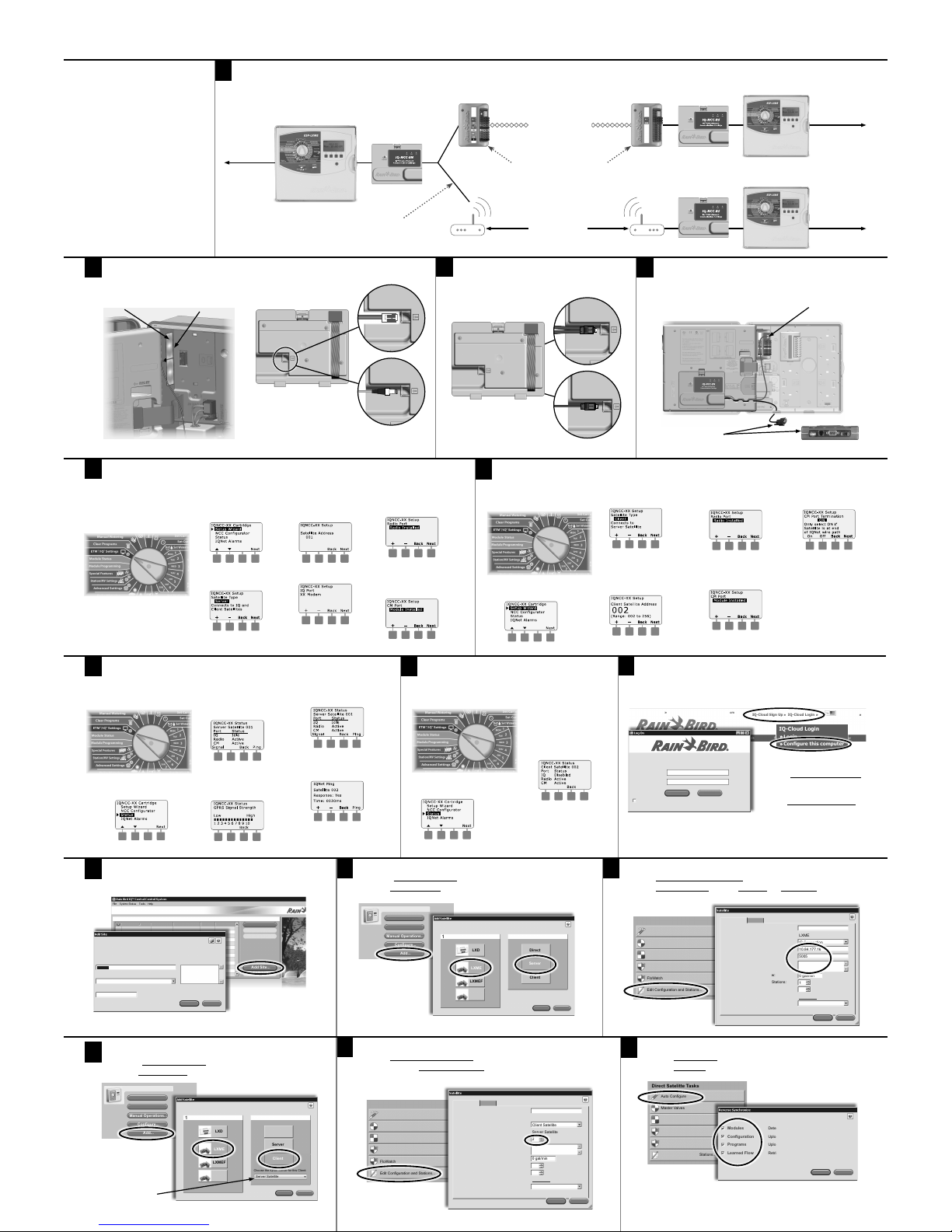
1
IQNet Server/Client Communication
• Connection Module (CM) PE- Cable and/or Radio Secondary Communication
IQNet Server/Client
Communication Overview
Allows a single Server Satellite with IQ primary communication connection (Cellular, Ethernet, etc.) to be shared with up to
255 Client Satellites via Radio and/or Connection Module (CM) PE-Cable secondary
communication.
a. Utilizes lower cost IQNCCRS RS-232
Cartridges for Client Satellites.
b. Reduces yearly reoccurring com-
munication costs for systems using
Cellular communication.
c. Provides Normally Closed Master
Valve or Pump Start sharing between Server and Client Satellites.
d. Provides Weather Sensor (not Flow
Sensor) sharing between Server
and Client Satellites.
Rain+Birdt
IQNCCRS RS-232 Network Communication Cartridge IQNet Server/Client Installation & IQ-Cloud Configuration
For Additional Information
See IQ-NCC Cartridge Installation
and Operations Guide for IQ3GUSA Cellular and IQNCCEN
Ethernet Cartridge Installation
and Configuration Instructions.
Go to www.RainBird.com/
for training, presentations,
product literature and
information for IQEnterprise and IQ-Desktop.
IQ-Cloud Support
(800) 254-0692
IQCloudSupport@RainBird.com
www.RainBird.com/IQ
Rain Bird Global Service Plan (GSP)
(866) 477-9778
www.GSPSupport@RainBird.com
9
Go to www.rainbird.com/iq
A
New users: Select IQ-Cloud Sign-up.
B
Existing users: Select IQ-Cloud Login.
10
Select Add Site
13
Add Client Satellites
A
Choose ESP-LX Controller Type.
B
Select Client IQNet Type.
14
Configure Client Satellites
A
Select Edit Configuration and Stations.
B
Enter the unique IQNet Network Address (2 to 56) that you selected in the
Setup Wizard for each Client Satellite.
15
Reverse Sync Data from each Satellite
A
Select Auto Configure.
B
Check All Options.
2018 Rain Bird Corporation
t
Registered trademark of Rain Bird Corporation
P/N: 690656-01 Rev. 6/18 D41261
3
Attach IQ Cables to Cartridges in Server and
Client Satellites
C
Select the
Server Satellite
this Client is
connected to.
12
Configure Server Satellite
A
Select Edit Configuration and Stations.
B
Select IP Connection Type, enter the IP Address and Port Number for IQ-Cloud
to communicate to the Server Satellite.
11
Add Server Satellite
A
Choose ESP-LX Controller Type.
B
Select Server IQNet Type.
2
Install IQ-NCC Cartridges
4
Attach IQ Cables to Radio/CM Module
Attach Supplied Y-Cable to Radios or Straight-Cable to CM Modules
8
Check IQNet Satellite Communication Status from
the Client Satellites
7
Test Satellite Communication from the
Server Satellite
B
The Setup - Satellite Type
screen is displayed. Use +
or - to select Direct' press
Next.
NOTE: The IQ Port status
will allways show Disabled for
Client Satellites.
g
Turn the controller dial to
ETM/IQ Settings
5
Setup Wizard for Server Satellite
g
Turn the controller dial to
ETM/IQ Settings
6
Setup Wizard for Client Satellite
g
Turn the controller dial to
ETM/IQ Settings
B
The Setup - Satellite Type screen is
displayed. Use + or - to select Client;
press Next.
C
The Setup – Satellite Address screen
is displayed. Use + or - to select a
unique address from 002-256 for
this satellite (press and HOLD buttons to accelerate settings); press
Next.
D
The Setup – Satellite Radio
Port screen is displayed. Use +
or - to select a radio port option (No Radio Installed, Radio
Installed); press Next.
E
The Setup – Satellite CM Port
screen is displayed. Use + or to select a CM Port option (No
Module, Module Installed);
press Next.
F
The Setup – CM Port
Termination screen is displayed. Use + or - to select a
CM Port Termination option
(On or Off).
NOTE: CM Port
termination is only
required if this satellite is
at the end of an IQNet PE
Communication Cable path.
If you are not sure, consult
with the system designer.
A
The IQ Settings main menu is
displayed. Use the UP or DOWN
arrows to select Setup Wizard;
press Next.
B
The Setup - Satellite Type
screen is displayed. Use + or to select Server; press Next.
C
The Setup – Satellite Address
screen is displayed. Server
Satellites always have an address of 001; press Next.
D
The Setup – Satellite IQ Port
screen is displayed; press Next.
E
The Setup – Satellite Radio
Port screen is displayed. Use +
or - to select a radio port option (No Radio Installed, Radio
Installed); press Next.
F
The Setup – Satellite CM Port
screen is displayed. Use + or
- to select a CM Port option
(No Module Installed, Module
Installed); press Next.
g
Turn the controller dial to
ETM/IQ Settings
A
The IQ Settings main menu is displayed. Use the UP or DOWN arrows to select Status; press Next.
B
The Satellite Status screen is
displayed. Current status of IQ,
Radio, and CM ports are shown.
Press Signal to display 3G signal
strength.
C
The Signal Strength is displayed.
The signal strength between the
satellite and the 3G Cellular network is indicated on a scale of
1-10.
D
The Satellite Status screen is displayed. Current status of IQ, Radio,
and CM ports are shown. Press
Ping to check the communication
status with selected Clients.
E
The IQNet Ping screen is displayed.
Use the + and - buttons to select
any Client address. Press Ping to
check the communication status.
The LCD will display Response-Yes
if the ping is successful, or No for
an unsuccessful ping.
A
The IQ Settings main menu is displayed. Use the UP or DOWN arrows
to select Setup Wizard; press Next.
A
The IQ Settings main menu is displayed. Use the UP or DOWN arrows
to select Status; press Next.
Install IQ3G-USA Cellular or
IQNCCEN Ethernet Cartridge
in Server Satellite
Install IQNCCRS RS-232 Cartridges
in the Client Satellites
NOTE: Refer to IQ3G-USA Cellular and
IQNCCEN Ethernet Cartridge Installation
Posters for full Installation instructions.
NOTE: Use Y-Cable for satellites that
have both a CM Module and Radio.
What’s NewIQ-Cloud Sign Up IQ-Cloud Login
EN
IQ-Cloud Support (800) 254-0692 | iqcloudsupport@rainbird.com
IQ-Cloud Login
Login
Configure this computer
Rain Bird IQ Central Control System
TM
User Name
Password
I forgot my password
Log On Cancel
What’s New
Show Quick Start
C
Select Configure this computer
for first time IQ-Cloud connection
on a new computer.
D
Enter User Name & Password to
Logon to IQ-Cloud.
3G Cellular
Antenna
Backplane
Connect DB9 Cable
end to Radio port
Connect 2-pin cable
end to CM Module
ESP-LX Controller
Server Satellite
IQ3G-USA or
IQNCCEN Cartridge
Supplied IQ-Y and Straight Cables
Connect Cartridges to CM's and Radios
IQFSCMLXME Flow Smart Connection Modules
for ESP-LXME Controllers and IQCMLXD
Connection Modules for LXD Controllers
To Internet
and IQ-Cloud
To Additional
Connection
Module Client
Satellites
To Additional
Radio or
Connection
Module Client
Satellites
IQNCCRS Cartridge
ESP-LX Controller
ESP-LX Controller
IQNCCRS Cartridge
19-Gauge PE
Cable, Twisted Pair,
Shielded, Gel Filled
Communication
Cable (Max 18K feet)
IQSSRADIO or RB-
SS-TN9B Radios
(separate antenna
and Radio Site
Survey required)
Attach IQ-Y Cable to Radio
IQ NCC Cartridges
Attach Straight-Cable for
Connection Modules (CM)
Client Satellite
 Loading...