

Page 1
ESP-LXIVM Controller
Troubleshooting Guide
Page 2

For product manuals, instructional videos and FAQs,
please visit: www.rainbird.com/esplxivm
For free professional support for programming and
troubleshooting, please call: 1-866-544-1406
Local Rain Bird Contact Information
Distributor Mgr:
Email:
Phone:
Area Specification Mgr
Public Agency Manager:
Email:
Phone:
Contractor Account Mgr:
Email:
Phone:
Water Conservation Mgr:
Email:
Phone:
2 ESP-LXIVM Controller Troubleshooting Guide
Table of
Contents
Page 3

Contents
Local Rain Bird Contact Information ..................................... 2
Tools ..................................................................... 4
Recommended ............................................................................. 4
Useful ............................................................................................... 5
LX-IVM Compatible Valves .................................5
Controller Features ............................................. 6
Front Panel .....................................................................................6
2-Wire Settings .............................................................................7
Diagnostics .................................................................................... 7
Cabinet Components ................................................................. 8
Basic Programming ............................................9
Troubleshooting Flow Charts .............................10
Getting Started ...........................................................................10
2-Wire Mapping .........................................................................11
No Water Days, No Run Times, … ........................................13
Shorted Paths ..............................................................................14
Shorted Path (Manual Method) .........................................15
Duplicate Address .....................................................................19
Flow Alarm ...................................................................................20
Ping Valve / Sensor (Ping Test) ..............................................22
Field Wiring Diagnostics ...................................23
Tools and Equipment ...............................................................23
Total System Milliamp Draw ..................................................23
3 ESP-LXIVM Controller Troubleshooting Guide
Table of
Contents
Page 4

Field Wiring Issues .....................................................................23
Broken Wire (Open Circuit) List Not Responding .........24
Short Circuit ..............................................................................25
Ground Fault .............................................................................26
Relay Wiring .................................................................................27
IVM Power Filter Connection .................................................29
Controller Diagnostics ...................................... 30
IVM Interface Module ....................................... 37
LED Indicators .............................................................................37
LED Status ....................................................................................38
Module Status ..........................................................................38
2-Wire Path Status ...................................................................38
Individual Path Status ............................................................38
Tools
Recommended
• MAXI Cable 2-Wire communications cable.
• Rain Bird WC20 splice kits for ALL electrical wiring connections.
• Rain Bird genuine Wire Stripper
For video showing proper wire splice instructions and other
installation tips, please visit:
www.rainbird.com/esplxivm
NOTE: If installing or repairing
communications wiring for
IQ Software, do not install
the communications
cables in the same conduit
as the 2-Wire path wiring.
Rain Bird
Wire Stripper
4 ESP-LXIVM Controller Troubleshooting Guide
Table of
Contents
Page 5
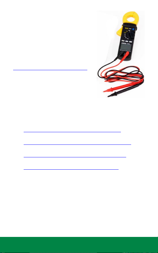
Useful
• Milliamp Meter
Recommended Model: Armada Pro 93
• As-Built Drawing
If you don’t have it, make it using a cable locator
• LX-IVM Troubleshooting Tools
A list of ESP-LXIVM Controller Troubleshooting Videos
can be found here:
https://www.rainbird.com/esplxivm
LX-IVM Compatible Valves
Videos for ESP-LXIVM compatible valves ,connecting and troubleshooting
can be found here:
• PGA Series
https://www.rainbird.com/products/pga-series
• PEB Series
https://www.rainbird.com/products/pebpesb-series
• EFB-CP Series
https://www.rainbird.com/products/efb-cp-series
• BPE Series
https://www.rainbird.com/products/300-bpes
NOTE: Rain Bird HV, DV, and JTV Series residential valves are not
compatible with IVM-SOL. Use only Rain Bird commercial series
valves for ESP-LXIVM installations:
NOTE: Physical intereference on any valves can be addressed
through “clocking” to avoid being “in-line” with IVM-SOL or
removing the component (e.g. Flow Control).
5 ESP-LXIVM Controller Troubleshooting Guide
Milliamp
Meter
Table of
Contents
Page 6
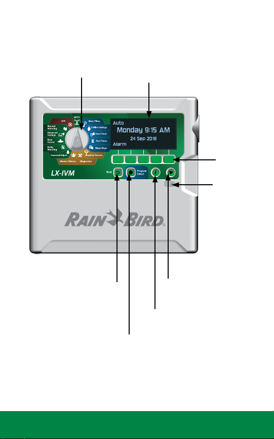
Controller Features
Front Panel
PROGRAMMING
DIAL
BACK BUTTON
PROGRAM
SELECT BUTTON
DISPLAY
PROGRAMMING
KEYS
ALARM
LIGHT
LANGUAGE
SELECT BUTTON
INFORMATION
BUTTON
6 ESP-LXIVM Controller Troubleshooting Guide
Table of
Contents
Page 7
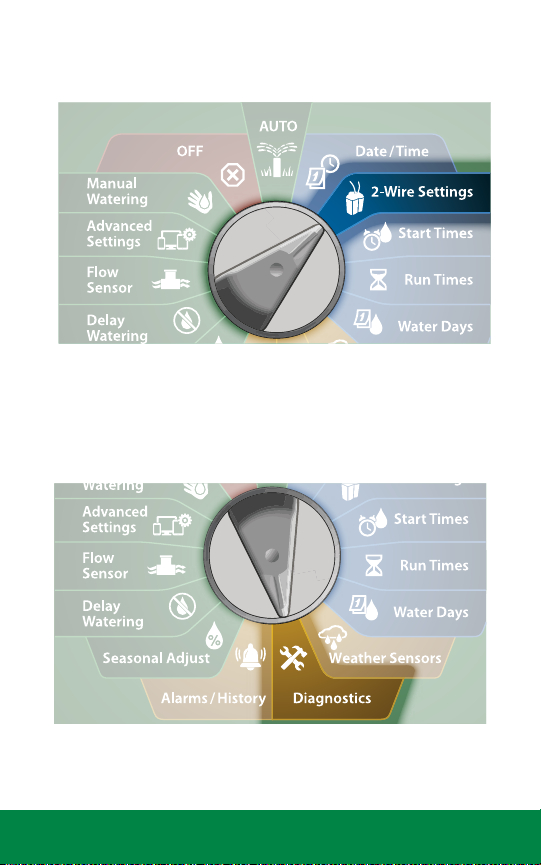
2-Wire Settings
Diagnostics
7 ESP-LXIVM Controller Troubleshooting Guide
Table of
Contents
Page 8
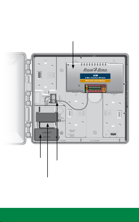
Cabinet Components
IVM 2WIRE INTERFACE MODULE
JUNCTION
BOX
TRANSFORMER
8 ESP-LXIVM Controller Troubleshooting Guide
CONNECTOR
Table of
Contents
Page 9

Basic Programming
The ESP-LXIVM Controller has 2-Wire Settings to help get you started
and guide you through each step of the installation and hardware
setup process.
It’s most effective to use the 2-Wire Settings in the order they appear in the
2-Wire Settings menu, as follows:
1. Master Valves
2. Weather Sensors (if present)
3. Station Setup
4. Flow Sensors (if present)
Installation, Programming & Operation Guide
For more information see the LX-IVM Field Device Installation Guide that
came with the LX-IVM Controller.
Or download the LX-IVM User Manual at:
www.rainbird.com/esplxivm
9 ESP-LXIVM Controller Troubleshooting Guide
Table of
Contents
Page 10
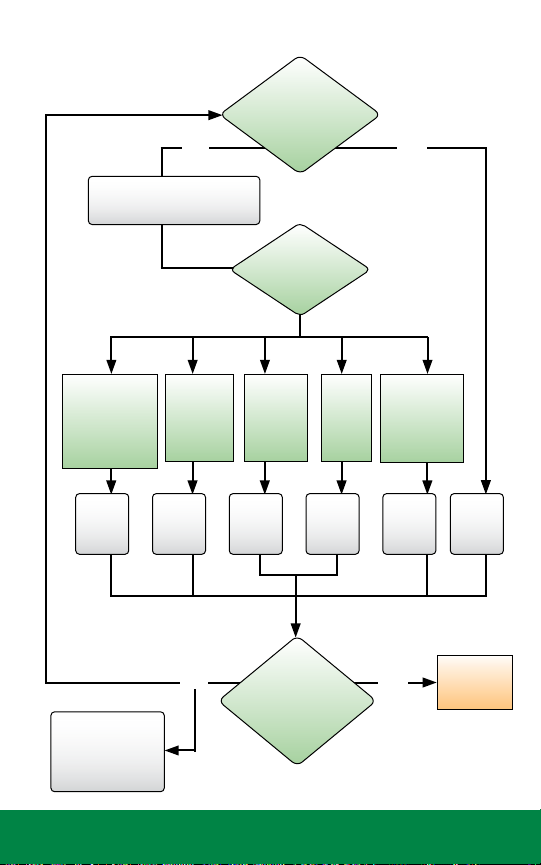
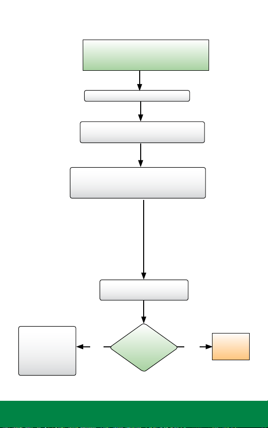
Troubleshooting Flow Charts
What does
the screen
display?
Is the LX-IVM
front panel
Alarm Light on?
Is the LX-IVM
front panel
Alarm Light
still on?
Getting Started
YES NO
Turn the dial to AUTO and
press the Alarm button
No Water Days
No Run Times
No Start Times
No PGM will...
More Exit
Shorted
Paths
Duplicate
Address
Flow
Alarm
Device Not
Responding
Go to
page
13
Call the ESP-LX
SeriesHOTLINE at
+1-866-5441406
10 ESP-LXIVM Controller Troubleshooting Guide
Go to
page
14
Go to
page
19
YES NO
Go to
page
20
Go to
page
22
Go to
page
23
END - Job
Well Done!
Table of
Contents
Page 11
2-Wire Mapping
Next
Next
Next
Start
2-Wire Mapping “maps” or records information on the wire-path of any
connected IVM devices. A total of 4 wire paths are available in a LX-IVM
Controller.
NOTE: While this information is helpful for diagnostics, not doing
2-wire mapping WILL NOT affect irrigation functions. But if 2-wire
mapping is NOT done, it will raise an alarm at the controller.
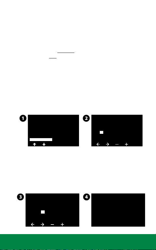
To initiate 2-wire mapping, follow the steps below:
Turn the Dial to 2-Wire Settings
1. At the Advanced Station Settings screen, press the Down Arrow
key to select 2-Wire Mapping, then press Next.
2. At the 2-Wire Device Mapping screen, press the + and – keys to
set the desired hour (from 0 to 23), then press the Right Arrow
key.
Advanced Station Settings
Cycle & Soak
Inter-Station Delay
SimulStations
Station Sequencing
2-Wire Mapping
2-Wire Device Mapping
Start Device Mapping In
00 00:
HH:MM
3. Press the + and – keys to set the desired minute (from 1 to 59),
then press Next.
4. At the confirmation screen, press Start to begin Device
Mapping.
NOTE: All irrigation is disrupted during the mapping process.
2-Wire Device Mapping
Start Device Mapping In
01
05:
HH:MM
11 ESP-LXIVM Controller Troubleshooting Guide
Attention
Device Mapping will
interrupt all irrigation
and could take several
minutes
Table of
Contents
Page 12
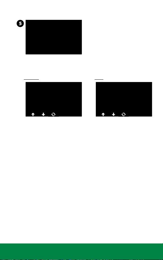
5. A confirmation screen shows the process is set to run.
Done
Cancel
Ping
Ping
Mapping
Mapping will begin
In 1 Hrs and 5
Mins.
The following pictures show the List Not responding screen without
and with 2-wire mapping done.
Without 2-wire mapping With 2-wire mapping
LIST NOT RESPONDING
AT 01/01/18
Type
STA
STA
STA008 --STA010 ---
002
004#---
12 : 00 PM
Path
---
LIST NOT RESPONDING
AT 01/01/18
Type
STA
STA
STA008 2
STA010 2
002
004#2
12 : 00 PM
Path
2
12 ESP-LXIVM Controller Troubleshooting Guide
Table of
Contents
Page 13

No Water Days, No Run Times, …
Is the
LX-IVM system
working?
Turn the dial to Date/Time and
ensure time and date are correct
Turn the dial to Start Times,
Run Times and Water Days
and follow programming
directions in the User Manual
Test LX-IVM system using
Manual Watering or Auto
Check the display
for Alarms, see
page 10
Troubleshooting
NO
YES
END - Job
Well Done!
13 ESP-LXIVM Controller Troubleshooting Guide
Table of
Contents
Page 14

Shorted Paths
The controller has automatically entered Short Finding
Mode to protect itself against a short on the 2-wire path
Turn the dial to Diagnostics and select
Diagnostics from the menu, then press Next
Press the Down Arrow button to select
Test Shorted Paths, then press Next
Press the Down Arrow button to select
the Path (1-4) to test, then press Next
Trouble Shoot in the Field using a milliamp meter.
A sharp increase in current should be observed
right before the Short Condition in 2-wire Path.
NOTE: Shorted Path will
display “Fault”.
Press and hold the Yes button
to energize the selected path
Note: Irrigation will be disabled
If issue cannot be resolved using the Shorted Paths Test, refer
to the Shorted Path (Manual Method) on the next page.
Next Page
14 ESP-LXIVM Controller Troubleshooting Guide
Table of
Contents
Page 15

Shorted Path (Manual Method)
Did the
controller exit Short
Finding Mode and are
both Indicator Lights
illuminated?
Open the front panel and check
the two indicator lights on the
IVM 2-Wire Interface Module.
The top indicator light should
be green and the bottom
indicator light should be
dark. This indicates that the
controller put the module in
Short Finding Mode
If there are more than one 2-wire paths
connected, disconnect the first 2-wire path
Disconnect the second/
third/fourth 2-wire path
NO YES
NOTE: In “looped”
systems, cut the loop in
the middle to create two
independent paths.
Reconnect the Maxi-Cable to verify the
controller goes back into Short Finding Mode
15 ESP-LXIVM Controller Troubleshooting Guide
Next Page
Table of
Contents
Page 16

Wires
damaged, or found
repairs of the
Maxi-Cable?
What does
the display
show?
Shorted Path (Manual Method) cont.
Repair damaged
Maxi-Cable
using Maxi
Cable and DRB/Y
connectors
YES
Go to an IVM device approx.
50% the length of the 2-wire
path. Disconnect the IVM device
2-wire splice to disconnect the
second half of the 2-wire path.
Reconnect the
Maxi-Cable to verify
the controller goes
back into Short
Finding Mode
Walk the length of
the 2-wire path and
look for signs of recent
constructions (trenching,
new fence, sign, tree, etc.)
NO
Connect all
2-wire paths at
NO
the controller
and observe
screen
Go back to
Troubleshooting,
page 10
NOTE: Instead of
physically disconnecting
the 2-wire path, you
could instead use
a clamp meter. See
page 18.
16 ESP-LXIVM Controller Troubleshooting Guide
Next Page
Table of
Contents
Page 17

Check the
controller display to
see if it has exited
Short Finding
Mode
Shorted Path (Manual Method) cont.
YES NO
The problem is downstream
between this point and the
end of the 2-wire path
Re-connect the 2-wire path
and go to an IVM device
approx. 50% between this
point and the end of the
2-wire path. Disconnect the
2-wire splice to disconnect the
second half of the 2-wire path.
NOTE: Once a small section 2-wire path is identified as having an
issue, use “Energize Path for Testing” and Milliamp Meter to track
for a sharp increase in test current before the location of the short.
For video instructions on Automatic Short
Finding Mode, please visit:
www.rainbird.com/esplxivm
17 ESP-LXIVM Controller Troubleshooting Guide
The problem is
upstream between this
point and the controller
Re-connect the 2-wire path
and go to an IVM device
approx. 50% between this
point and the controller.
Disconnect the 2-wire splice
to disconnect the second
half of the 2-wire path.
Next Page
Table of
Contents
Page 18

Shorted Path (Manual Method) cont.
Alternatively you can measure current draw in your system using
Diagnostics/ Diagnostics/Controller Output:
NOTE: Before measuring the amperage, calculate the approximate
current that the 2-wire path is consuming.
System Amperage Calculation
Quantity of IVM-SOL X 0.67 mA
Quantity of IVM-OUT X 0.67 mA
+
Quantity of other IVM-SEN X 6 mA
+
Approximate total system amperage in mA
=
If there is a mismatch, follow a process similar to page 10 to disconnect
50% of devices and redo calculation above. Continue todisconnect 50% of
devices until you identify section of 2-wire Path with issues.
NOTE: Self-healing: Note that IVM Controller tracks the health
of the 2-wire Path to see if shorts are resolved and then
automatically resumes irrigation. You do not need go back to the
Controller to reset or restart.
For video instructions on Locating a Short
on the Two-Wire Path, please visit:
www.rainbird.com/esplxivm
18 ESP-LXIVM Controller Troubleshooting Guide
Table of
Contents
Page 19
Duplicate Address
Is the
LX-IVM system
working?
The controller will Alarm if duplicate
device addresses are entered for one or
more of IVM-SOL, IVM-SEN and IVM-OUT.
Turn the dial to 2-Wire Settings
Press the Down Arrow button to
select Station Setup, then press Next
Use the + and - buttons to cycle through all
the stations. Verify that all 2-wire addresses
are correct and there are no duplicates.
NOTE: Only the first two
duplicates will be shown,
so you may need to repeat
this process until all of
the duplicates have been
addressed.
Test LX-IVM system using
Manual Run or Auto Run
Check the display
for Alarms,
see page 10
Trouble-
shooting
19 ESP-LXIVM Controller Troubleshooting Guide
NO YES
END - Job
Well Done!
Table of
Contents
Page 20

Flow Alarm
Go Back and select FloZone Flow Alarms
Alarms are issued when flow conditions
exceed your High or Low Flow settings.
Turn the dial to Alarms/History
Press the Down Arrow button to
select Flow Alarms, then press Next
Press the Down Arrow button to select
Station Flow Alarms, then press Next
Troubleshoot and fix any
station that shows an alarm
CONTINUED
FROM NEXT
PAGE (21)
Troubleshoot and fix any
FloZone that shows an alarm
Next Page
20 ESP-LXIVM Controller Troubleshooting Guide
Table of
Contents
Page 21

Flow Alarms cont.
Alarm is
cleared on
the display
After fixing any station or FloZone issues,
go Back and select Clear Flow Alarms
Run all zones manually
Check the Alarms screen to see if previous alarm cleared
NO YES
GO BACK
TO PREVIOUS
PAGE (20)
21 ESP-LXIVM Controller Troubleshooting Guide
END - Job
Well Done!
Table of
Contents
Page 22

Ping Valve / Sensor (Ping Test)
Assumption: A valve or sensor may not be working
Turn the dial to Diagnostics
Press the Down Arrow button to select
Ping Valve/Sensor then press Next
Press the + and - buttons to select the type of device to test
(Station, Master Valve, Flow Sensor, Weather Sensor, etc.)
Press the <> button to select the number
of the device to test, then press Ping
The controller will ping the selected device and
report a voltage reading if the device responds
Interpreting Ping Results
If the device does not respond verify the address and check the wire
splices. The voltage reading is a measurement of the charge of the
device capacitors.
If the voltage is low, wait a minute then ping again.
If the voltage is still low (below 23 volts), disconnect the device
from the 2-wire path and connect directly to an unused wire path at
Controller and repeat Ping Test. If the voltage is fine, the issue is with
2-wire path / splicing. If the voltage is still bad, replace the device.
22 ESP-LXIVM Controller Troubleshooting Guide
Table of
Contents
Page 23

Field Wiring Diagnostics
The ESP-LXIVM Controller includes multiple diagnostic functions to help
you determine the cause of a field wiring issue.
Tools and Equipment
• An accurate “as-built” showing wire path and 2-wire device locations,
the number and type of the 2-wire devices on each wire path, and
2-wire addresses
• Filled out LX-IVM Controller Programming Guide with 2-wire
addresses and station/MV/sensor assignments
• A Volt/Ohm Meter (multi-meter) capable of reading 0 to 50 volts AC/
DC and resistance from 0 to 1,000,000 Ohms
• A Clamp Meter for measuring AC current with a precision of 1.0 mA
(milliamp)
• Wire tracing and fault finding equipment
• Spare system components and tools including: spare IVM-SOL, IVMSEN device, WC20 Splice Kits and wire strippers
Total System Milliamp Draw
Before troubleshooting a field wiring issue, calculate the expected total
system draw in milliamp (mA). This value can be compared to actual
readings during troubleshooting.
• Each IVM-SOL, IVM-OUT draws 0.67mA
• IVM-SEN draws 6 mA
• Add up the total devices of each type for each wire path and
calculate the wire path mA draw
• Add the mA for each wire path together for the total system mA
draw
Field Wiring Issues
Field wiring issues are typically caused by a broken wire, a short circuit or a
ground fault in the 2-wire path. Refer to the section that best describes the
observed symptoms to troubleshoot.
• Broken Wire (Open Circuit)
• Short Circuit
• Ground Fault
Next Page
23 ESP-LXIVM Controller Troubleshooting Guide
Table of
Contents
Page 24

NOTE: A majority of field wiring issues are caused by poor wire
splices. Use only WC20 Splice Kits. All splices should be made in
splice boxes.
NOTE: If the 2-wire path is Looped, disconnect the loop half way
out before troubleshooting.
Broken Wire (Open Circuit) List Not Responding
If there is a broken wire causing an open circuit in the 2-wire path, you
will notice one or more stations are not running even though they are
programmed to operate. If the system is using flow sensing, you will
receive a low (zero) flow alarm for each disconnected 2-wire station.
Controller Diagnostics
1. Turn the dial to Test All Stations / Check System. Select 2-Wire
Diagnostics.
2. Select the List Not Responding. The results will indicate that
one or more devices have an open circuit and you will be
prompted to Check Wiring. Go to the location of the 2-wire
devices that are not responding and check all wire splices.
2-Wire Path Diagnostics
1. Note the “List Not Responding” displays and corresponding
wire paths. If you notice that all the 2-wire devices that are not
responding are in a single leg of the 2-wire path, the open
circuit exists between the last working 2-wire device and
the first non-working 2-wire device. Check the splices at that
location first. Also look for signs of recent construction/digging
between the working and non-working 2-wire devices.
NOTE: If 2-Wire mapping is not done, the wire path column will
not include any information.
2. Turn the controller dial to 2-Wire Diagnostics; Select Short
Finding; Turn Short Finding Mode On. Use a Clamp Meter to
measure the Amp Draw of the 2-wire path cable conductors at
the last working device and the first non-working device. Note
any discrepancies in the readings. You must know the number
and type of each device downstream to know what the mA
reading up should be reading (see the Total System Milliamp
Draw section for more information).
24 ESP-LXIVM Controller Troubleshooting Guide
Table of
Contents
Page 25

Short Circuit
If there is a short circuit (can be caused by crossed red and black wires)
in the 2-wire path, the controller Alarm light will be illuminated and the
alarm will inform you the controller has switched to Short Finding Mode.
You must fix the short circuit before the controller will switch back to
normal irrigation mode.
2-Wire Path Diagnostics
1. Disconnect each 2-wire path cable one at a time from the
controller IVM 2-Wire Interface Module until the controller exits
Short Finding Mode. Reconnect that 2-wire path cable, and if
the Short Finding Mode returns you know the short is on that
leg of the 2-Wire path.
2. Refer to the as-built to see the location of the 2-wire path. Walk
the route of the 2-wire path cable and check for signs of recent
construction/digging.
3. Find a device location about half-way down the 2-wire path
cable. Disconnect the splices. See if the controller is still in
Short Finding Mode. If the Short Finding Mode has cleared, the
problem is downstream of this location. If the controller is still
in Short Finding Mode, the problem is between this location
and the controller. Keep disconnecting segments of the 2-wire
path until you isolate the problem.
4. Use a Clamp Meter to measure the Amp Draw of the 2-wire
path cable conductors at the last working device and the first
non-working device. Note any discrepancy in the readings. You
must know the number and type of each device downstream to
know what the mA reading up should be reading (see the Total
System Milliamp Draw section for more information).
5. The problem may be caused by a device that was damaged by
a lightning power surge. The controller will exit Short Finding
Mode when the damaged device is disconnected from the
2-wire path.
25 ESP-LXIVM Controller Troubleshooting Guide
Table of
Contents
Page 26

Ground Fault
A ground (earth) fault can be caused when a 2-wire path conductor
is leaking to ground, possibly due to a bad wire splice, or a nicked or
damaged cable. This issue may come and go depending on the soil
moisture level. When the soil is very wet the problem will be worse than
when the soil is dry.
Controller Diagnostics
1. Turn dial to Diagnostics / Diagnostics / Control Output.
2. Select Controller. Note the Milliamp (mA) reading. The mA
reading will be higher than normal when current is leaking
to ground. You must know the number and type of each
device in the system to know what the mA reading should be
reading (see the Total System Milliamp Draw section for more
information).
3. Disconnect each 2-wire path cable one at a time from the
controller IVM 2-Wire Interface Module. Recheck the Control
Output to isolate which segment of the 2-wire path has the
ground fault.
4. Find a device location about half-way down the 2-wire path
cable. Disconnect the splices.
5. Check the Control Output to see if the ground fault has been
isolated. If the Control Output is normal, the problem is
downstream of this location. If the Control Output still shows
the ground fault, the problem is between this location and the
controller. Keep disconnecting segments of the 2-wire path
until you isolate the problem.
2-Wire Path Diagnostics
1. Turn the controller dial to Diagnostics / Diagnostics / Test
Shorted Path.
2. Use a Clamp Meter to measure the Amp Draw of the 2-wire
path cable conductors at various splice locations. Note any
discrepancy in the readings. You must know the number and
type of each device downstream to know what the mA reading
up should be reading (see the Total System Milliamp Draw
section for more information).
26 ESP-LXIVM Controller Troubleshooting Guide
Table of
Contents
Page 27

Relay Wiring
For valves without compatible latching solenoids.
IVM-SOL device can be used to connect any Rain Bird Commercial Valve
to the LX-IVM Controller. For Non-Rain Bird Valve, use IVM-OUT device in
conjunction with a compatible DC latching solenoid to connect to a LX-IVM
controller. In the event, a compatible DC latching solenoid is not available,
you can use the Rain Bird Pump Start Relay with following modifications to
power the AC Solenoid.
1. Connect 110V relay to the + or - 24VAC terminals at the
controller’s IVM 2-wire Interface Module.
NOTE: Do not connect 2-wire path to the 110V relay terminals.
2. Unplug PSR relay coil wires and output to AC Solenoid.
NOTE: Feed the solenoid wires through bottom of the PSR
enclosure.
27 ESP-LXIVM Controller Troubleshooting Guide
Table of
Contents
Page 28

3. Connect the red and white IVM-OUT wire to the red wire of the
DC Latching Relay. Connect the black and white IVM-OUT wire to
the black wire of the DC Latching Relay.
4. Connect the red IVM-OUT wire to the red wire on the 2-Wire
path. Then connect the black IVM-OUT wire to the black wire on
the 2-Wire path.
Input Power
from 24VAC
Out Terminal
at Controller
IVM-OUT
AC Solenoid
Model Nos.
PSR110-IVM
and PSR220-IVM
Allow 3 ft. (1 m)
Extra Cable
Length
28 ESP-LXIVM Controller Troubleshooting Guide
AC Solenoid
Table of
Contents
Page 29

IVM Power Filter Connection
Electrical Noise in the input power can cause undesirable behavior of the
LXIVM Controllers. Sources of Electrical Noise include VFD Pump and other
Electrical Equipment.
Rain Bird recommends the GSP-IVM Filter to filter the noise from the input
power and ensure normal operation of the Controller. Symptoms can include
inconsistent operation of the stations (stations not running as programmed)
and inability read flow from a compatible flow sensor.
Rain Bird recommends the following modification to the controller to “filter
out” the noise and ensuring normal operations of the Controller.
Choke: Schaffner
P/N: RD5122-6-9M6
Terminal Block
on LX-IVM
ORANGE
YELLOW
ORANGE
YELLOW
GREEN or GREEN YEL.
(not connected)
(24VAC IN)
BLUE
BROWN
GROUND
LX-IVM Transformer
(26.5VAC Out)
NOTE: IVM Filter Kit can be sourced from Rain Bird GSP via the
online services store (link below).
https://servicesstore.rainbird.com/ivm-filter.html
29 ESP-LXIVM Controller Troubleshooting Guide
Capacitor, Kemet P/N:
C274ACF5100SA0J
Table of
Contents
Page 30

Controller Diagnostics
Use this table to troubleshoot issues using the built-in diagnostic features
of the ESP-LXIVM controller.
Category Issue Potential Cause Solution
Controller
Alarms
Red alarm
light on the
controller
front panel is
illuminated.
Controller
alarm; No
2-Wire Module.
Controller
alarm; 2-Wire
path Off.
Controller
alarm;
Duplicate
Device Address.
Controller
alarm; Short
Finding Mode.
Controller
alarm; No
Device
Addresses.
The controller is
reporting an alarm
condition.
The IVM 2-Wire
Interface Module
is not properly
attached to the
controller module
slots.
Someone has
manually turned the
2-wire path Off.
Duplicate Device
addresses have been
entered.
2-wire path is
shorted and the
controller has
automatically
switched to the
Short Finding Mode.
The lower left
status light on the
controller is dark.
Device addresses
have not been
entered for any
stations.
Turn dial to Auto, press the Alarm button,
review the alarm conditions, and address
the issue(s).
Check the upper status light on the IVM
2-Wire Interface Module. It should be solid
green if it is properly connected to the
controller. Remove and reinstall the module
making sure it is fully seated in the module
slots.
Turn dial to Off, press the 2-Wire Path button,
and turn the 2-wire path On.
Note the duplicate Device Addresses posted
in the alarm screen, verify and enter the
correct Device addresses.
Disconnect the 2-wire cables from the IVM
2-Wire Interface Module one at a time until
the alarm condition clears. The lower left
status light on the controller will alternate
between red and green when the wire path
with the short is removed.
Trace the path of this 2-wire cable and look
for source of issue (disturbed soil, new tree or
fence post, etc).
Disconnect the 2-wire cable halfway between
the controller and end of cable and check to
see if the alarm clears to help identify short
location on the cable.
Use a volt/ohm and clamp meter to identify
which devices are receiving power.
Fix the short and check that the alarm is
cleared.
Turn dial to 2-Wire Settings / Station Setup.
Enter the address (see label on each Device)
for each station. Addresses are also required
for Master Valves, Weather Sensors and Flow
Sensor.
30 ESP-LXIVM Controller Troubleshooting Guide
Table of
Contents
Page 31

Category Issue Potential Cause Solution
Controller
Alarms
Controller
alarm; Zero
Learned
Flow.
Controller
alarm; Flow
Alarm.
The Learn Flow
Utility has recorded
a zero (0) flow rate
for one or more
station.
FloWatch (flow
sensing utility) has
detected a high or
low flow condition.
Turn dial to Flow Sensor / Set Flow Rates /
View Flow Rates / View Station Rates. Check for
stations that have a 0 flow rate and are labeled
Learned.
• If all stations have learned a 0 flow check flow
sensor/ input connections, Flow Sensor configuration, FloZone assignments, etc.
• If only one or a few stations have learned a
0 flow rate check the valve operation (flow
control stem position, solenoid, wiring, etc.).
• If just small flow rate valves/stations (like drip
zones) have learned a 0 flow rate the flow
sensor may be too large for the lower flow
rates. Check the product technical specs for the
minimum flow rate of the flow sensor.
Turn dial to Alarms / History / Flow Alarms,
and review the posted Station and/or FloZone
(mainline) flow alarms. Note the station(s) or
FloZone(s) that were identified. If you configured
FloWatch to Diagnose & Eliminate or Alarm &
Shut Down, the problem station(s) or FloZone(s)
will be quarantined. Clear the Flow Alarms and
test the system.
• Station flow alarms – Manually turn on the
station. Turn dial to Flow Sensor / View Current
Flow. The current and expected flow rates
will be listed. Check the valve & sprinklers to
identify the issue and correct it. If sprinklers or
nozzles have been replaced, relearn the station
flow rate.
• FloZone alarms - Manually start a program.
Turn dial to Flow Sensor, View Current Flow. The
current and expected flow rates will be listed.
Check the water source(s) and mainline to
identify the issues and correct it.
• If FloZone high flow alarms are being triggered
by manual watering (QCV, manually bleeding
valves, etc.) consider using the MV Water
Window located under the Manual Watering
dial position. Configure window open and
close times, days of the week, MV(s) you want
open, and the
expected additional flow rate to allow for the
manual watering.
31 ESP-LXIVM Controller Troubleshooting Guide
Table of
Contents
Page 32

Category Issue Potential Cause Solution
Controller
Alarms
2-Wire Path
Issues
Controller alarm;
Invalid Module
Config.
Controller alarm;
No PGM will Auto
Run.
Controller
Alarm; No
Power – Irrigation
Functions are
Disabled.
Communication
with 2-wire
devices is
intermittent.
Controller loses
connection to
2-wire devices
after a heavy
irrigation or
rainfall event.
A non-compatible
module has been
inserted into one
of the controller
module slots.
Incomplete
programming.
No primary power
to the controller
transformer
Front panel
ribbon cable is
disconnected
2-wire cable
or splices are
leaking to ground
or between
conductors.
Communication
signal and power
leaks to ground.
Remove any recently added modules, one at a
time, until the alarm condition clears.
• ESP-LXME/-LXMEF Controller 4-, 8-, &
12-Station Modules, FSM Flow Smart
Modules, M50 and SM75 Modules are not
compatible.
Turn dial to Diagnostics / Confirm Programs
/ Program Summary. Missing programming
parameters are identified by an N. For
programs to automatically run you need to
program Start Days, Start Times, and Station
Run Times.
Check the power input to the controller
transformer. The display is being powered by
the 9v backup battery.
Check both ends of the ribbon cable to make
sure it is firmly connected to the backplane
and front panel.
Turn dial to Diagnostics / Control Output. The
controller voltage output and 2-wire path
milliamp draw will be displayed.
• If there are no issues you will see Current
Limit OK, Current Overload OK.
• If the 2-wire cable leaks are drawing a high
amount of current you will see Current
Limit Not OK, Current Overload OK. Use the
troubleshooting tips above to find and fix
the 2-wire cable/splice issues.
• If the 2-wire cable leaks are drawing a high
amount of current you will see Current
Limit Not OK, Current Overload Not OK.
The controller will have automatically
switched to Fault Finding Mode. Use the
troubleshooting tips above to find and fix
the 2-wire cable/splice issues.
• Single-jacketed cable and/or incorrect
wires splices were used. When incorrect
cable/splices become submerged it can
create leakage to ground. Double- jacketed
14-2UF Maxi 2-Wire Cable and WC20 Splice
Kits are required.
32 ESP-LXIVM Controller Troubleshooting Guide
Table of
Contents
Page 33

Category Issue Potential
IVM-SEN/
Sensor
Programs Programs
Station
Sequencing
The controller
is not getting
data from
a flow or
weather
sensor
connected to
a IVM-SEN/
Sensor on the
2-wire path.
are running
at random
times.
Stations are
not running
in station
number
sequence
Cause
Sensor wiring
polarity is
reversed.
Flow sensor
output pulse rate
is not compatible
with the LX-IVM
Controller.
Weather sensor
type is not
compatible.
Multiple start
times have been
programmed
unintentionally.
Water Windows
have been
configured so
programs are
paused and
resume later.
Station
Sequencing set
to Sequence by
Station Priority
Solution
Many sensor including flow sensors require wires
to be connected with correct polarity (+ / -). If
the sensor has colored or labeled wires, connect
as follows:
• Sensor red (+) wire to the IVM-SEN Sensor
red wire.
• Sensor black (-) wire to the IVM-SEN Sensor
black wire.
The LX
-IVM Controller requires a minimum input
of 2 pulses per 10 seconds for the smallest station
flow rate. Pulse rates of less than 2 pulses per
10 seconds will not be registered.
compatible flow sensor.
The LX-IVM Controller is not compatible with 4-20
mA or 0-5V weather sensors (discrete switched
sensors only).
Turn dial to Diagnostics / Confirm Programs /
Review Program. Review each program using the
Program Button to select the program. Check for
multiple start times on an individual program. In
some cases users’ mix-up start times and stations
and can inadvertently program the system to
start multiple times per day.
Turn dial to Delay Watering / Water Window. Use
the Programs Button to select a program 1 - 40.
Water Windows control the hours of the day
a program is allowed to operate. If a program
starts outside a Water Window it is paused until
the window opens. If the program is still running
when the Water Window closes the program is
paused and will automatically start the next time
the window opens. Adjust the Water Window
open and close times to allow the program to
complete.
The LX-IVM offers 2 station sequencing modes:
• Sequence by Station Numbers (default) – Sta-
tion selection criteria: a) Non-Irrigation Priority;
b) Station number low to high; c) Program
assignment 1 - 40.
• Sequence by Station Priority (automatically
used if FloManager is On) – Station selection
criteria: a) Station Priority Non-Irrigation, High,
Medium, Low; b) Station Run Time longest
to shortest; c) Station number low to high; d)
Program Assignment 1 - 40.
To change Station Sequencing mode turn dial to
2-Wire Settings / Advanced / Station Sequencing.
Use the +/- softkeys to change the selection.
Change to a
33 ESP-LXIVM Controller Troubleshooting Guide
Table of
Contents
Page 34

Category Issue Potential Cause S olution
Station
Valves
Station
Valves
Master
Valves
A station
valve is not
operating.
A station
valve is not
operating.
The Master
Valve will not
open when
stations are
operating.
Valve is manually
closed or solenoid
is damaged.
Station does not
have run time for a
program with start
days and a start
time.
IVM-SOL or valve
wires are not
spliced correctly.
Incorrect address. Check the address of the station (label on the IVM
Incorrect Valve
Type
2-wire path from
the controller is
not connected to
this area.
MV is assigned to
a different FloZone
than the stations.
MV is Normally
Open but has been
configured as a
Normally Closed
MV.
Station not
configured to open
Master Valve.
MV Address is
incorrect.
Turn dial to Manual Watering / Start Station. Select
the station making sure it has a run time and press
run. Check to see if the valve is operating and if it
isn’t, address the valve issue.
Turn dial to
Run Time. Note which programs the station has run
times programmed. Use Program Summary to make
sure that program has start days and start times.
Turn dial to Diagnostics / Diagnostics / Ping List not
Responding. If the ping test fails check the device
and valve wire splices and repeat the ping test.
device that is connected to the valve) and verify
the address is entered correctly. Turn dial to 2-wire
Setting / Station Setup to access Station Address.
Turn Dial to 2-wire Setting / Station Setup / Valve
Types. Valve types configure the decoder inrush
amps and duration for opening a valve solenoid.
The LX-IVM Valve Types are preconfigured for
Rain Bird commercial valve models. Information
for configuring Valve Types to work with other
valves can be found in the controller manual. Note:
Rain Bird residential valves (DV, JTV, HV) are not
compatible with the LX-IVM system or IVM-SOL.
Ping other valves on the same 2-wire path leg.
If these pings are also unsuccessful, check for an
open wire connections on the 2-wire path.
Turn dial to 2-Wire Settings / Master Valves. Press
Next to advance to FloZone (FZ) Setup screen. MV
needs to be assigned to the same FloZone as the
stations that receive water from this water source.
If the MV valve is Normally Open (powered to close)
it needs to be configured as Normally Open. Turn
dial to 2Wire Settings / MV Setup. Change MV from
Normally Closed (default) to Normally Open.
Go to 2-Wire Settings / Station Setup to make sure
the station is configured as requiring a Master
Valve.
Check the address of the MV (label on the IVM
device that is connected to the MV) and verify the
address is entered correctly. Turn dial to Setup
Wizards / Master Valves to access MV Address.
Diagnostics / Confirm Program
/ Station
34 ESP-LXIVM Controller Troubleshooting Guide
Table of
Contents
Page 35

Category Issue Potential Cause Solution
Master
Valves
IVM 2-Wire
Interface
Module
Pump Start
Relays
Controller
LCD Display
The Master
Valve will not
open when
stations are
operating.
No output
from the
module.
The controller
cannot close
the pump
start relay that
is connected
to a IVM-OUT.
The controller
display is either
too light or too
dark.
Controller
display is
blank.
2-wire device or
valve wires are not
spliced correctly.
IVM-Device is not
functioning or
damaged.
Fuses in the module
have blown due to
short or secondary
power connected to
the 2-wire path.
Module is in
Automatic Short
Finding Mode due to
short or secondary
power connected to
the 2-wire path.
Amp draw of the
pump start relay
is more than the
Device can provide.
The display contrast
needs to be
adjusted.
Controller LCD
display is damaged.
Primary power to
the controller has
been lost or turned
off.
Controller ribbon
cable is not
connected or
damaged.
Turn dial to Diagnostics / Diagnostics /
MV and ping the MV address. If the ping
Ping
test fails
check the decoder and valve wire splices and
repeat the ping test.
Turn dial to
Valve or Sensor, then ping the MV address. If the
ping test fails swap the device, enter the new
address and repeat the ping test.
Find the source of the short or power
connected to the 2-wire path and address
the problem. A replacement 2-wire Module is
available for purchase.
Find the source of the short or power
connected to the 2-wire path and address
the problem.
Use a Rain Bird PSR-Series Pump Start Relay
that incorporates an ice-cube relay, double
relay system. You can also add an ice -cube
relay to the existing pump start relay. Contact
Rain Bird Technical Services or Global Support
Plan for relay model and wiring diagram.
Turn dial to Off, press Contrast +/- buttons to
adjust display contrast.
Plug in a 9V battery into the battery slot
on the back of the controller front panel. If
information is now visible on the display it
is not damaged and working correctly. See
other potential causes. If no information is
displayed, remove the 2-wire module. If the
alarm light on the front panel turns on after 1
minute but no information is in the display, the
LCD is damaged and the front panel should
be replaced. A replacement panel is available
for purchase.
This can be verified by checking the status
lights on the 2-wire module. If both status
lights on the module are dark the primary
power is likely off. Find primary power source
to the controller and turn it on. If the power
breaker is tripped or fuse is blown, find source
of problem, fix the issue, and turn the power
back on.
Check to make sure the ribbon cable is securely
connected to both the controller backplane and
the front panel. If the cable has broken wires or
connectors, replace it.
Diagnostics / Diagnostics /
Select
Ping
35 ESP-LXIVM Controller Troubleshooting Guide
Table of
Contents
Page 36

Category Issue Potential
Simul
Stations
(Simultaneous
Station
Operation)
Weather
Sensors
Controller
Knockouts
Too many
or too few
stations are
operating
simultaneously
when
program(s)
operate.
Weather
sensor is not
preventing
controller
manual
operation.
Wireless
weather
sensor is not
providing
input to the
controller.
I am having
trouble
removing the
knock-outs
on the
ESP-LX Series
Controller
plastic cabinet.
Cause
LX-IVM
(Controller)
SimulStations
are configured
incorrectly.
PGM (Program)
SimulStations
are configured
incorrectly.
This is by
design.
Sensor receiver
is not wired to
the controller
module
correctly.
Unlike knockouts on a metal
enclosure,
these plastic
knock-outs are
designed to be
removed by
applying force
to the center at
the dimple.
Solution
Turn dial to 2-wire Setting / Advanced /
SimulStations. Select LX-IVM SimulStations
and adjust the maximum number of
simultaneous irrigation stations you want to
allow to operate across all programs at any
time. Non- Irrigation SimulStations control
stations with Non-Irr Priority.
Turn dial to 2-wire Setting / Advanced
SimulStations. Select PGM SimulStations
and adjust the maximum number of
simultaneous irrigation stations you want
to allow to operate simultaneously within
the currently selected program. Move
the Program Button to select the other
programs 1 - 40.
Manual station, program or test program
operation (from the front panel or a remote)
is allowed regardless of the weather sensor
state. To see the current state of a weather
sensor, turn the dial to Weather Sensors. The
status of each sensor is displayed.
The IVM 2-Wire Interface Module includes
4 terminals for wireless weather sensor
connections. Wiring connections should be
made as follows:
• Sensor receiver power wires to + and –
terminals.
• Sensor receiver sensor wires to Sen and
C terminals.
Prior to installing the cabinet, place on a flat
surface with the knock-out facing up. Locate
the dimple in the center of the knock-out
you wish to remove. Place the tip of a large
Phillips screwdriver in the dimple. Use a
rubber or wooden mallet to firmly strike
the top of the screwdriver. The knock-out
should pop out in a single piece. If it breaks,
use pliers to remove the pieces. Do not use a
flat-bladed screwdriver around the outside
of the knock-out as this could crack the case.
36 ESP-LXIVM Controller Troubleshooting Guide
Table of
Contents
Page 37

IVM Interface Module
This section explains the LED Status indicators on the IVM 2-Wire Interface
Module.
LED Indicators
MODULE STATUS
2WIRE PATH
STATUS
1
2 3 4
INDIVIDUAL PATHS
37 ESP-LXIVM Controller Troubleshooting Guide
Table of
Contents
Page 38

LED Status
Module Status
Module State Description LED Light
POWER OFF Power off or module is held in reset. Dark
POWER UP During initial power up or after reset Briefly lights GREEN
ENUMERATION or ERROR Waiting for enumeration. Flashing RED
CONFIGURATION After enumeration, while receiving
NORMAL After configuration download is
SHORT ADDRESS
CONFIGURATION
device addresses and configuration from
the front panel
complete (from front panel and setting
all IVM-SEN to either flow or weather).
This is the Normal up and running state.
During the Normal state, there are
devices in the field that have not yet
been programmed with short addresses.
All other normal communication to field
devices still function while in this state.
2-Wire Path Status
Module State Description LED Light
POWER OFF Power off or module is held in reset. Dark
2-wire ON Normal state with 2-Wire path powered
2-wire OFF 2-Wire path powered down. Dark
on.
Individual Path Status
to indicate power
applied
Flashing ORANGE
Solid GREEN
Flashing GREEN
Blinking GREEN
Module State Description LED Light
POWER OFF Power off or module is held in reset. Dark
Individual path enabled Path connected (2-Wire path may be
Individual path disabled Path disconnected (2-wire path may be
on or off).
on or off).
Solid GREEN
Solid RED
38 ESP-LXIVM Controller Troubleshooting Guide
Table of
Contents
Page 39

Rain Bird Corporation
6991 E. Southpoint Road
Tucson, AZ 85756
Phone: (520) 741-6100
Questions?
Call the Rain Bird Professional Support Line at
+1-866-544-1406
or else visit our web site at
www.rainbird.com/esplxseries
Rain Bird Rewards:
www.rainbird.com/rewards
Phone - 1-888-370-1814
Global Service Plan:
www.rainbird.com/gsp
Phone: 866-GSP-XPRT (477-9778)
Registered trademark of Rain Bird Corporation
2020 Rain Bird Corporation 23DE20
 Loading...