

Rain Bird ESP-6LX+, ESP-8LX+, ESP-20LX+, ESP-24LX+, ESP-8LXi+ Installation, Programming, And Operation Manual
...Page 1
1
ESP-LX+ & LXi+ Installation, Programming, & Operation Guide
Rain Bird Sales, Inc. - Turf Products
970 W. Sierra Madre, Azusa, CA 91702
www.rainbird.com
P/N 634415-B
Installation, Programming, & Operation Guide
ESP-LX+ and ESP-LXi+
Indoor Models
ESP-8LXi+
ESP-12LXi+
ESP-16LXi+
Indoor / Outdoor Models
ESP-6LX+ ESP-16LX+
ESP-8LX+ ESP-20LX+
ESP-12LX+ ESP-24LX+
Page 2
Special Upgrade Oer
Save an extra 15% o new sprinkler timers and
irrigation controllers at the Rain Bird Online Store.*
Still struggling with your old sprinkler
timer? Having a hard time complying
with local watering restrictions?
Upgrading to a new Rain Bird sprinkler
timer is easier than you might think.
New timers are easier to program than
ever before, with powerful features to
help save you time and water while
keeping your yard healthy and vibrant.
There are lots of models to meet your
needs, including indoor and outdoor
versions, exible modular timers and
even smart controllers that
automatically adjust themselves
based on the weather.
Shop Now at store.rainbird.com and
enjoy exclusive upgrade savings!
UPGRADE15
at checkout to save an extra 15% o*
* Additional discount not valid on clearance items, bundles or store specials.
Discount applies to controller products only. Cannot be combined with
other store discount codes. Valid at the Rain Bird Online Store only.
Enter discount code:
Subject to change without notice.
® Registered trademark of Rain Bird Corporation.
Page 3

2
ESP-LX+ & LXi+ Installation, Programming, & Operation Guide
TABLE OF CONTENTS
Introduction ....................................................................................... 2
LX+ and LXi+ Series Controllers.................................................. 2
Controller Stations ................................................................... 2
Station Layout .......................................................................... 3
Controls, Switches, and Indicators ................................................ 4
Programming the Controller ............................................................... 6
Definitions ..................................................................................... 6
Programming Under Battery Power ............................................. 6
Programming Checklist ................................................................ 7
Fill Out Programming Chart .......................................................... 8
Clear All Program Information ..................................................... 10
Set Time...................................................................................... 11
Set Date ...................................................................................... 12
Select Program........................................................................... 13
Set Watering Day Cycle............................................................... 14
Custom .................................................................................. 14
Cyclical .................................................................................. 16
Odd/Even Cycle .................................................................... 18
Set Station Watering Times .......................................................... 19
Set Program Start Times ............................................................. 21
Set Water Budget........................................................................ 23
Set Station Delays ....................................................................... 24
Set MV / Pump Starts ................................................................. 26
Set Rain Delay............................................................................. 28
Set Calendar Days OFF .............................................................. 29
Set Sensor System and Bypass Switch ...................................... 31
Operating the Controller ................................................................... 33
Operate Controller Automatically ................................................ 33
Run Program(s) Manually ........................................................... 34
Run Station(s) Manually .............................................................. 35
Run Test Program ....................................................................... 36
Rapid Station Test Routine RASTER........................................... 37
Introduction ................................................................................ 37
RASTER Operation ..................................................................... 38
Running a RASTER (Rapid Station Test Routine) ......................... 38
Valve Testing ............................................................................... 40
Troubleshooting Open and Shorted Valve Circuits ...................... 43
Open Circuits ......................................................................... 43
Short Circuits ......................................................................... 44
Installing the Controller .................................................................... 45
Installation Checklist .................................................................... 45
Select Location ........................................................................... 46
Remove Door and Face Panel.................................................... 48
Mount Controller on Wall ............................................................. 50
Connect Field Wires .................................................................... 52
Field Wire Entrances .............................................................. 52
Station Valve Wiring ............................................................... 53
Master Valve Wiring ............................................................... 53
Sensor System Wiring ........................................................... 54
Pump Start Relay Wiring ............................................................. 55
Connect Main Power Wires ......................................................... 56
ESP-LX+ (Outdoor / Indoor Controller)................................. 56
ESP-LXi+ (Indoor only Controller) ......................................... 60
Install Battery .............................................................................. 62
Diagnostic Circuit Breaker .......................................................... 64
Troubleshooting ............................................................................... 65
Page 4

1ESP-LX+ & LXi+ Installation, Programming, & Operation Guide
ATTENTION: UN DISJONCTEUR OU UN INTERRUPTEUR DOIT ETRE
INSTALLE SUR LE PRIMAIRE POUR ISOLER LE PROGRAMMATEUR.
LA MEMOIRE EST MAINTENUE GRACE A UNE BATTERIE RE-
CHARGEABLE A DISPOSER SELON LA REGLEMENTATION
LOCALE.
Léclair avec le symbole de la flèche, placé dans les
limites dun triangle èquilatéral est prévu pour avertir
lutilisateur de la présence de tension dangereuse
non isolé dans lenceinte du produit qui pourrait ëtre
dune importance suffisante pour présenter un risque
dèlectrocution aux personnes.
Le point dexclamation dans un triangle èquilatéral est
prévu pour avertir lutilisateur de la présence
dinstructions importantes pour les opérations et
lentretien (service) dans les manuels fournis avec
lappareil.
WARNING: A CIRCUIT BREAKER OR CUTOFF SWITCH IS TO BE
PROVIDED IN THE FIXED WIRING TO ISOLATE THE CONTROL-
LER.
MEMORY IS RETAINED BY A BATTERY, WHICH IS TO BE DIS-
POSED OF IN ACCORDANCE WITH LOCAL REGULATIONS.
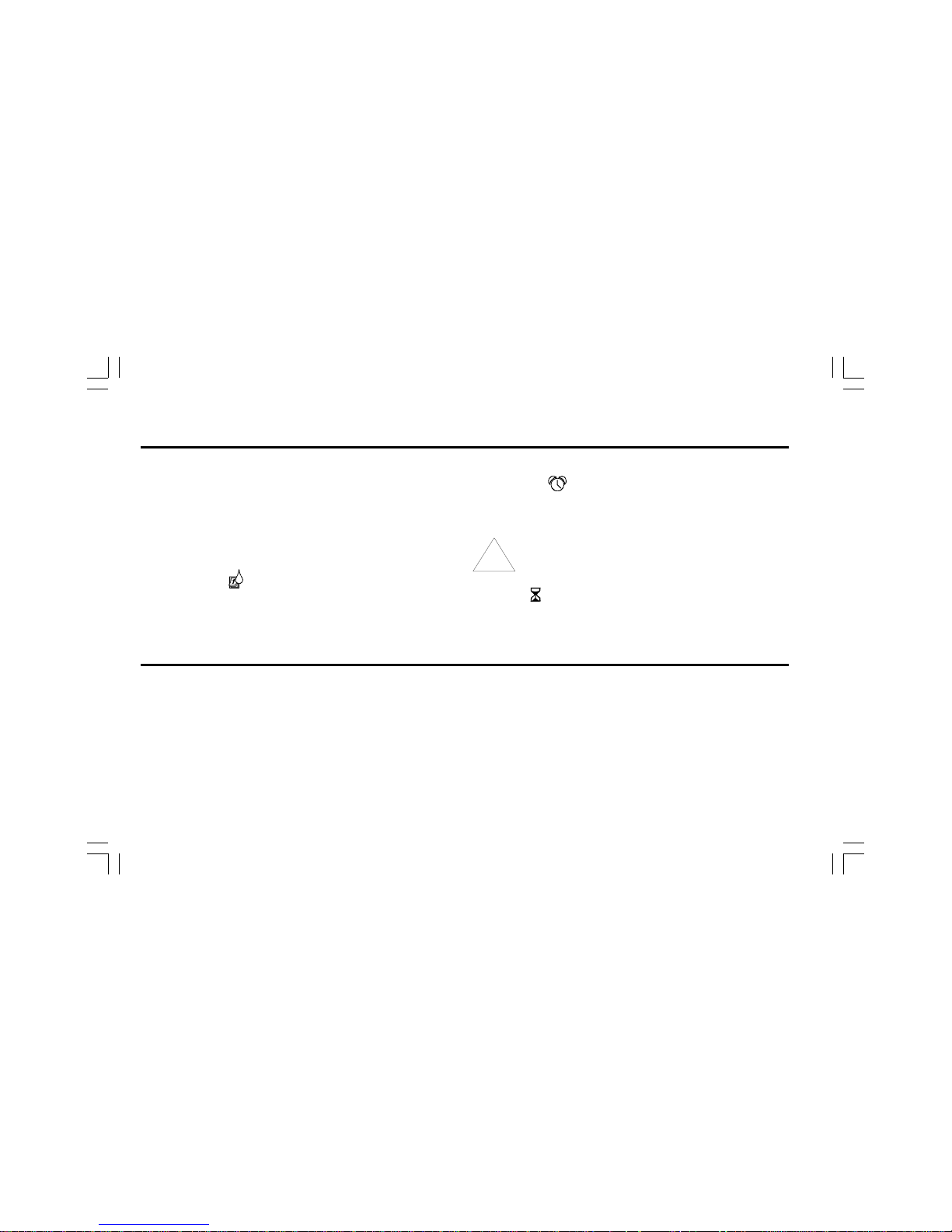
CAUTION ICONS
The lightning flash with arrowhead symbol, within an
equilateral triangle, is intended to alert the user to the
presence of uninsulated dangerous voltage within
the products enclosure that may be of sufficient
magnitude to constitute a risk of electronic shock to
persons.
The exclamation point within an equilateral triangle is
intended to alert the user to the presence of important
operating and maintenance (servicing) instructions in
the literature accompanying the product.
Page 5

2 ESP-LX+ & LXi+ Installation, Programming, & Operation Guide
INTRODUCTION
LX+ and LXi+ Series Controllers
The ESP (Extra Simple Programming) -LX+, -LXi+ Series
controller is an irrigation timing system for residential and light
commercial use.
The ESP-LX+ comes in 6-, 8-, 12-, 16-, 20-, or 24-station
models, designed for either indoor or outdoor use. The
ESP-LXi+ comes in 8-, 12-, or 16-station models, for indoor use
only.
ESP-LX+ and ESP-LXi+ controllers bearing the
remote ready icon (shown at right) can be
connected to Rain Birds Radio Frequency (RF)
receivers (RM-1R & RMX-1R).
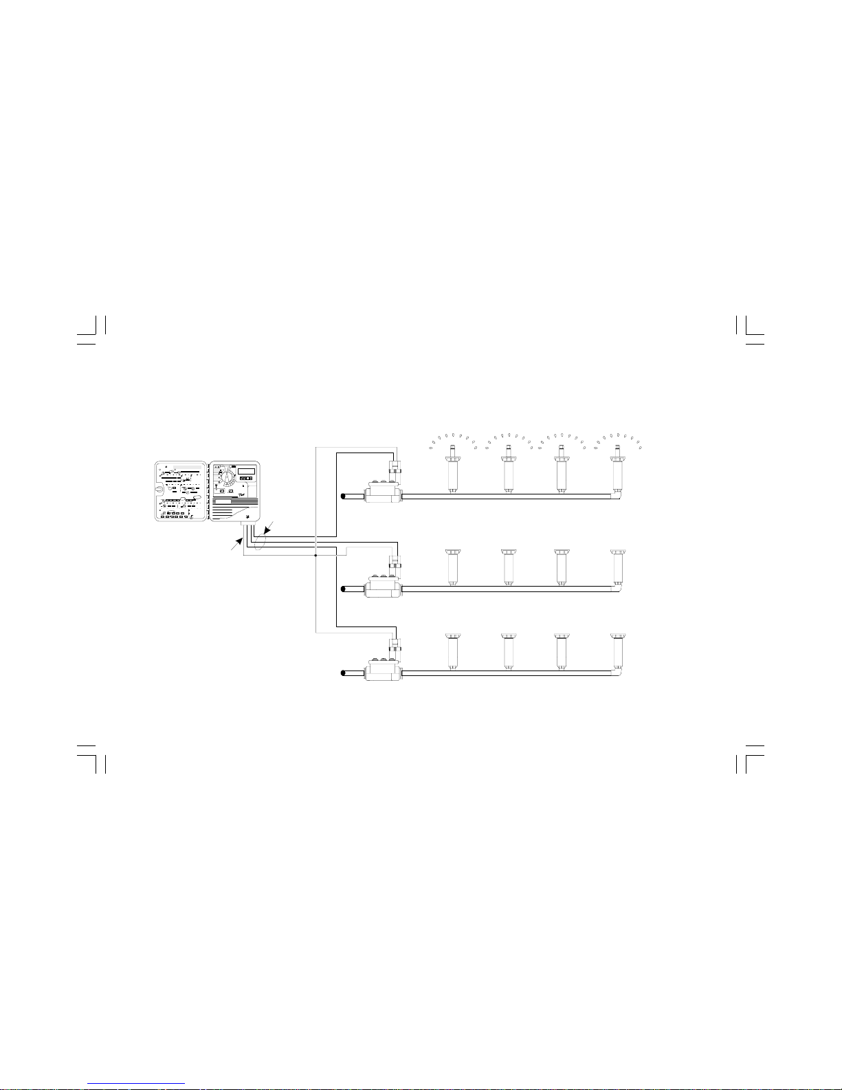
For example, the illustration on page 3 shows that station 1 is
currently watering. When station 1 is finished, the controller
will shut it off and start station 2. In the same way, station 3 will
begin watering when station 2 is finished.
NOTE: ESP-LX+ and -LXi+ controllers let you set a
delay between stations. For example, if you set a oneminute delay, station 1 will run until finished, followed
by a one-minute delay. Then station 2 will operate,
followed by a one-minute delay.
Controller Stations
Your ESP-LX+ or LXi+ Series controller is an electronic clock
that controls when your sprinkler system turns on, and how
long the sprinklers run. The controller has several sprinkler
stations connected to it, as shown in the illustration on the
following page. Each station is connected to a remote control
sprinkler valve.
The valve opens when it receives power from the controller,
and the sprinklers connected to that valve turn on. When these
sprinklers have run for their programmed time, the controller
shuts off the valve and opens the next valve in sequence.
Page 6
3ESP-LX+ & LXi+ Installation, Programming, & Operation Guide
Station Layout
Page 7
4 ESP-LX+ & LXi+ Installation, Programming, & Operation Guide
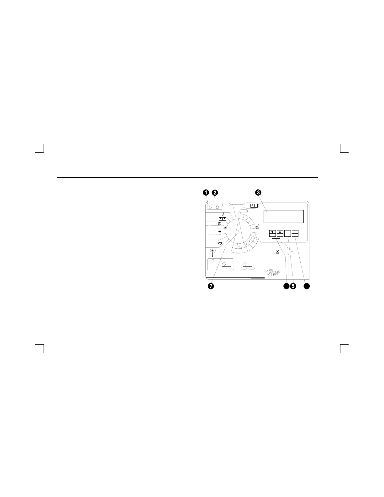
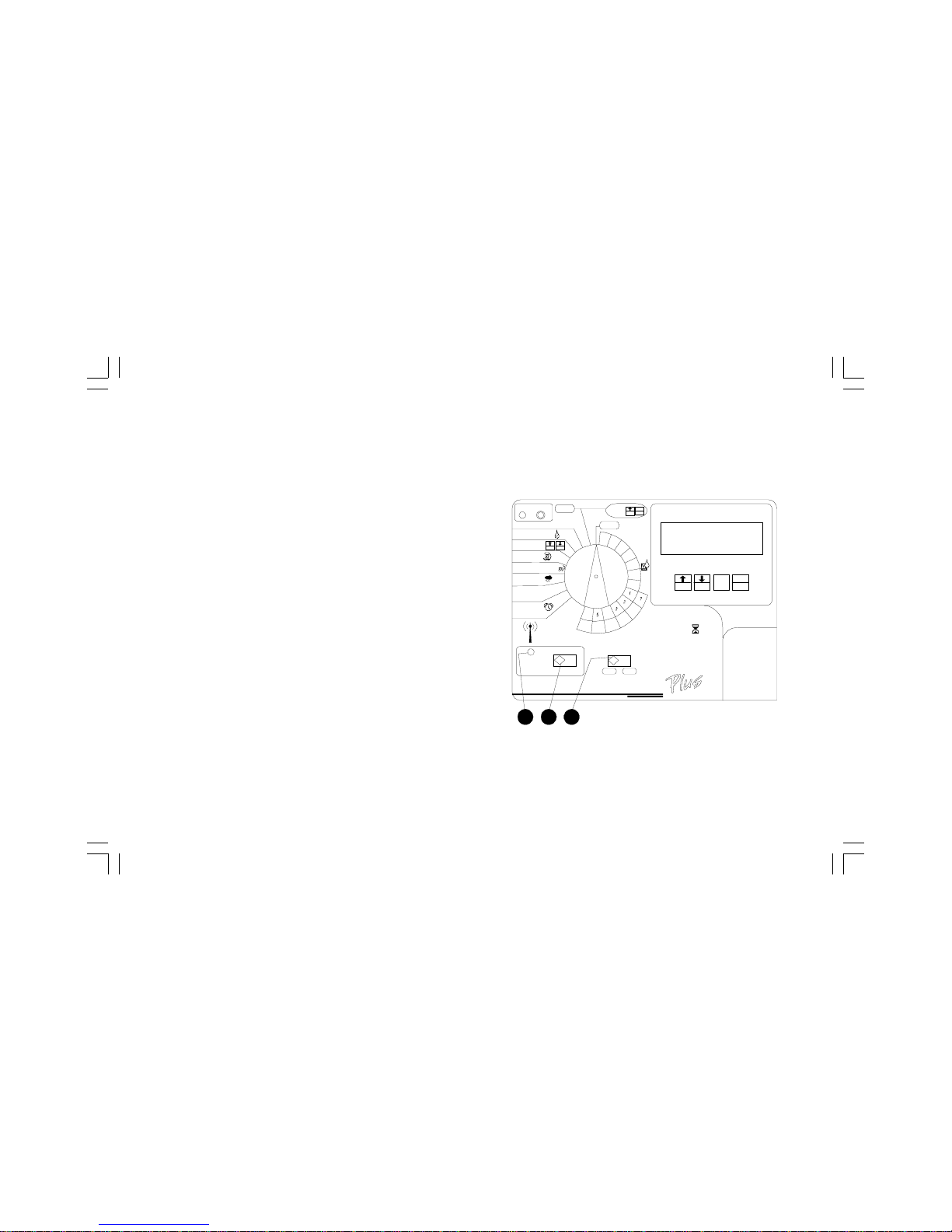
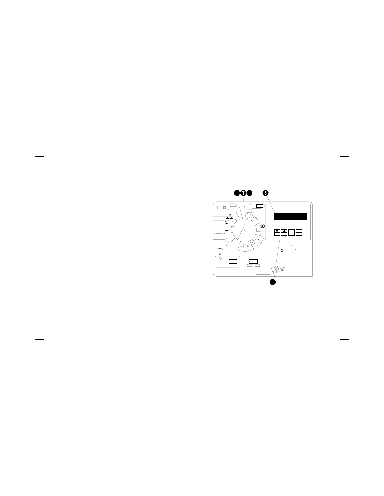
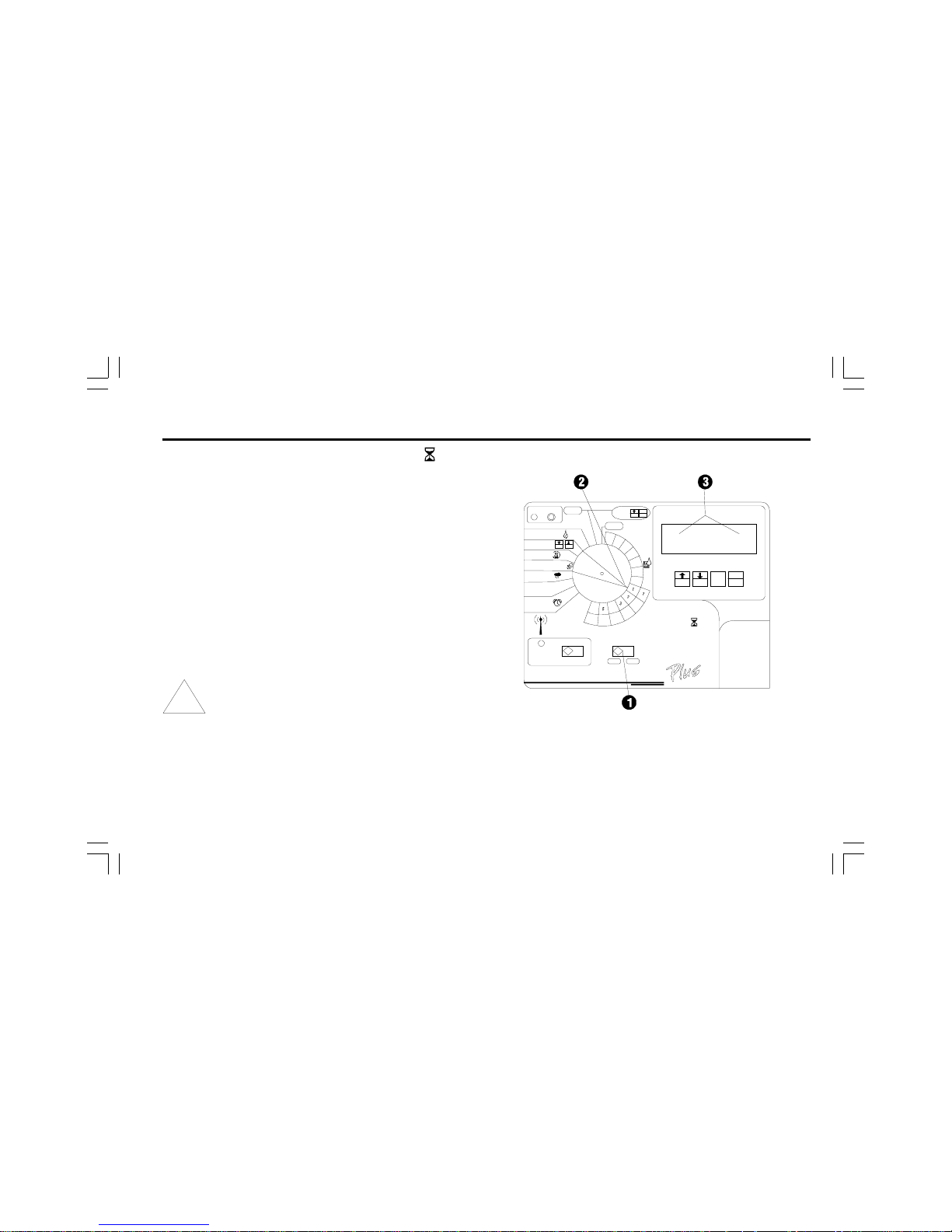
Controls, Switches, and Indicators
This illustration shows the controls, switches, and indicators on
ESP-LX+ and LXi+ controllers, including:
➊ Fault LED flashes when the controller senses a station
short circuit.
➋ Clear Fault Button used to turn off the Fault LED and
clear the flashing LCD Error indicator after the fault has
been corrected.
➌ LCD Display during normal operation, displays the time
of day; during programming, shows the result of your
commands; during watering, shows the station that is
running and the minutes remaining in its run time (when
program dial is set to the AUTO position).
➍ Manual Start / Advance Button used to start a program
manually or to manually advance watering from one
station to the next. Also used to make program changes.
➎ PGM Button used to select watering program A, B, C, or
D-drip.
➏ Arrow / ON-OFF Buttons used to set times and days, and
to make program changes.
Programming Dial used to turn the controller off and on,
and for programming.
Page 8
5ESP-LX+ & LXi+ Installation, Programming, & Operation Guide
➑ Watering Suspended by Sensor LED glows when watering
is prevented by a moisture sensor.
➒ Sensor Bypass Switch used to tell the controller to obey
or ignore input from a moisture sensor system. (Sensor
systems are optional.)
➓ Stations Slide Switch used to select one of the station
rows around the Programming Dial. (For 12-, 16-, 20-, and
24-station models only.)
Page 9
6 ESP-LX+ & LXi+ Installation, Programming, & Operation Guide
• Start time(s) - the time(s) of day that the program
begins; this is the time that the first station in the program
begins watering; all other stations in the program then
follow in sequence.
NOTE: The term start time refers to the time that a
program starts not to the time that each individual
station begins to run.
• Run time - the number of minutes (or hours and minutes)
that each station runs.
PROGRAMMING THE CONTROLLER
Programming Under Battery Power
If you wish, you can remove the front face panel of the controller and program the unit under battery power. This feature can
be useful if the controller is installed in an area that is not
readily accessible. This feature also lets you enter program
information before installing the controller at the job site.
Definitions
Programming is the process of telling the controller exactly
when and how long you want to water. The controller opens
and closes the remote control valves according to the program you set.
Each program contains:
• Watering days - the specific days of the week on which
watering takes place (for example, Monday, Wednesday,
Friday), or the watering interval (for example, every third day,
or only on even or odd days of the month).
To program the ESP-LX+ or ESP-LXi+ controller under battery
power, install the battery as described on page 62. To remove
the face panel, see the instructions on page 48. The controller
can be programmed under battery power, but should not be
operated on battery power alone. Connect the controller to an
AC power source as soon as possible to avoid battery drain.
Page 10

7ESP-LX+ & LXi+ Installation, Programming, & Operation Guide
Programming Checklist
To program the ESP-LX+ or LXi+ controller for the first time,
we recommend that you complete the following steps in order.
For your convenience, a check-off box (❐) is provided for each
step.
❐ Fill out Programming Chart .................................................. Page 8
❐ Clear all program information ............................................... Page 10
❐ Set time and date................................................................. Page 11
For each program:
)*+,
❐❐❐❐Select program (A, B, C, or D-drip). ... Page 13
❐❐❐❐Set watering day cycle ....................... Page 14
❐❐❐❐Set station watering times. ................. Page 19
❐❐❐❐Set program start time(s). ................... Page 21
❐❐❐❐Set water budget (optional). ............... Page 23
❐❐❐❐Set station delays (optional). .............. Page 24
❐ Set master valve / pump starts for each station (optional). . Page 26
❐ Set rain delay (optional). ...................................................... Page 28
❐ Set calendar day(s) OFF (optional). ..................................... Page 29
❐ Set sensor system and bypass switch (optional). ............... Page 31
❐ Set controller to automatic operation. ................................. Page 33
❐ Run test program (optional). ................................................. Page 36
Page 11

8 ESP-LX+ & LXi+ Installation, Programming, & Operation Guide
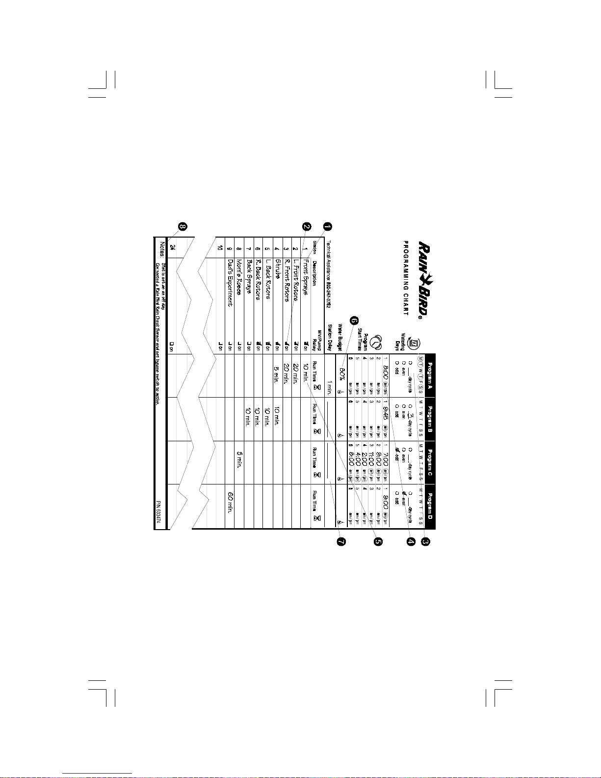
Fill Out Programming Chart
Before you begin programming, fill out the Programming Chart
and attach it to the inside of the controller door. A sample
Programming Chart is shown on page 9. Follow these instructions to complete the chart.
➊ Describe the sprinklers or plant zones covered by each
station on the controller.
➋ Indicate which stations drive a master valve or booster
pump relay by checking ON in the MV / Pump column.
(See page 26 for more information).
➌ In the Program A column, for Custom cycle, circle the
specific days of the week; for Cyclical schedule, write the
cycle period (e.g., 3-day cycle means every third day);
for ODD/EVEN-day watering, check ODD or EVEN.
➍ Enter the start time for Program A. You may enter up to six
start times for each program, but only one is needed to run
the program.
NOTE: Start times apply to the program, not to the
individual stations assigned to the program. In this
example, Program A begins watering at 8:00 a.m. on
Mondays, Tuesdays, Thursdays, and Saturdays.
Station 1 runs for ten minutes, followed by Station 2
for 20 minutes, Station 3 for 20 minutes, and Station 4
for 5minutes. The entire program takes about an
hour.
➎ Enter the watering run time (in hours and minutes) for each
station assigned to Program A.
➏ Enter the water budget percentage by program. The water
budget for sample Program A is set to 80%.
➐ Enter the station delays for Program A. A station delay is
the time between the end of one stations operation and
the beginning of the next. Use a station delay to let a water
well recover or to allow slow-closing valves to turn off
completely. If neither of these situations applies to your
site, leave the station delay set to 0. A station delay setting
applies to all stations in the program.
In the sample chart, Program A has a one-minute delay
between stations. When Station 1 ends, the controller waits
one minute before starting Station 2. There will also be a
one-minute delay between Station 2 and Station 3, etc.
➑ Make any special notes in the space provided.
➒ Repeat steps 2 through 7 for Programs B, C, and D.
NOTE: Stations assigned to Program D cannot be
used in any other programs. See page 19 for more
information.
Page 12
For E S P -LX + a nd LX i+ Co n trollers
D
9ESP-LX+ & LXi+ Installation, Programming, & Operation Guide
Page 13
10 ESP-LX+ & LXi+ Installation, Programming, & Operation Guide
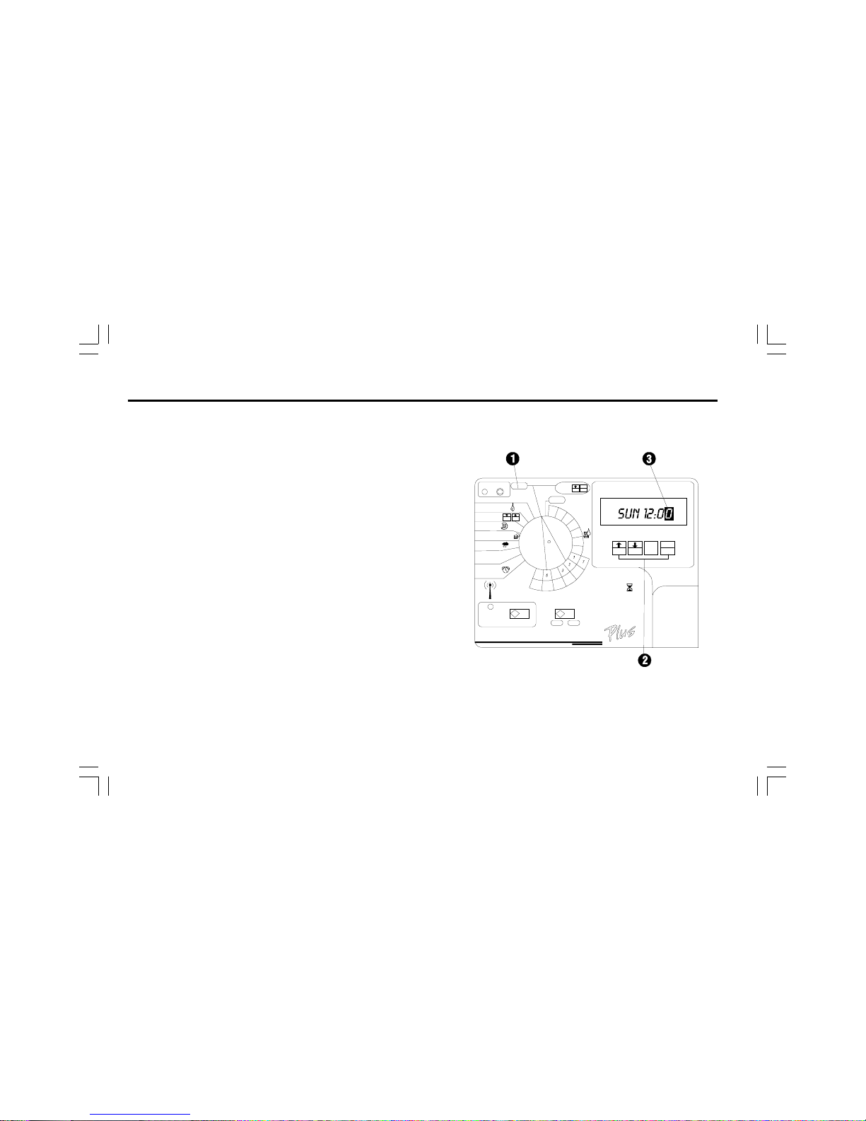
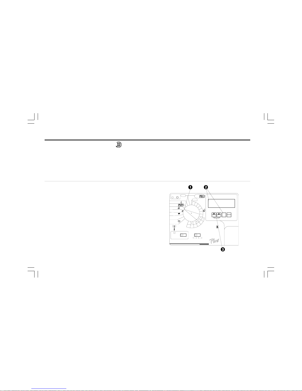
Clear All Program Information
To ensure you begin with a clean setup, clear the controller of
all existing program settings.
➊ Turn the dial to OFF.
➋ Hold down ON and MAN. START/ADV. for about seven
seconds until the display reads INITSYS and then begins to
scroll.
➌ When the last digit in SUN 12:00 flashes in the display, the
existing program settings have been cleared.
Page 14
11ESP-LX+ & LXi+ Installation, Programming, & Operation Guide
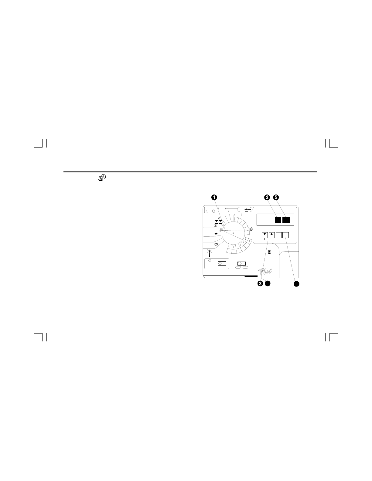
Set Time
Before you can program the controller, you must set its internal
clock to the correct time and date.
➊ Turn the dial to TIME & CALENDAR.
➋ The hour digits in the display flash.
➌ Press ñ or ò to set the current hour. Make sure the AM/
PM indicator is set to the correct designation.
➍ Press MAN. START/ADV.
➎ The minutes digits in the display flash.
➏ Press ñ or ò to set the current minute.
Page 15
12 ESP-LX+ & LXi+ Installation, Programming, & Operation Guide
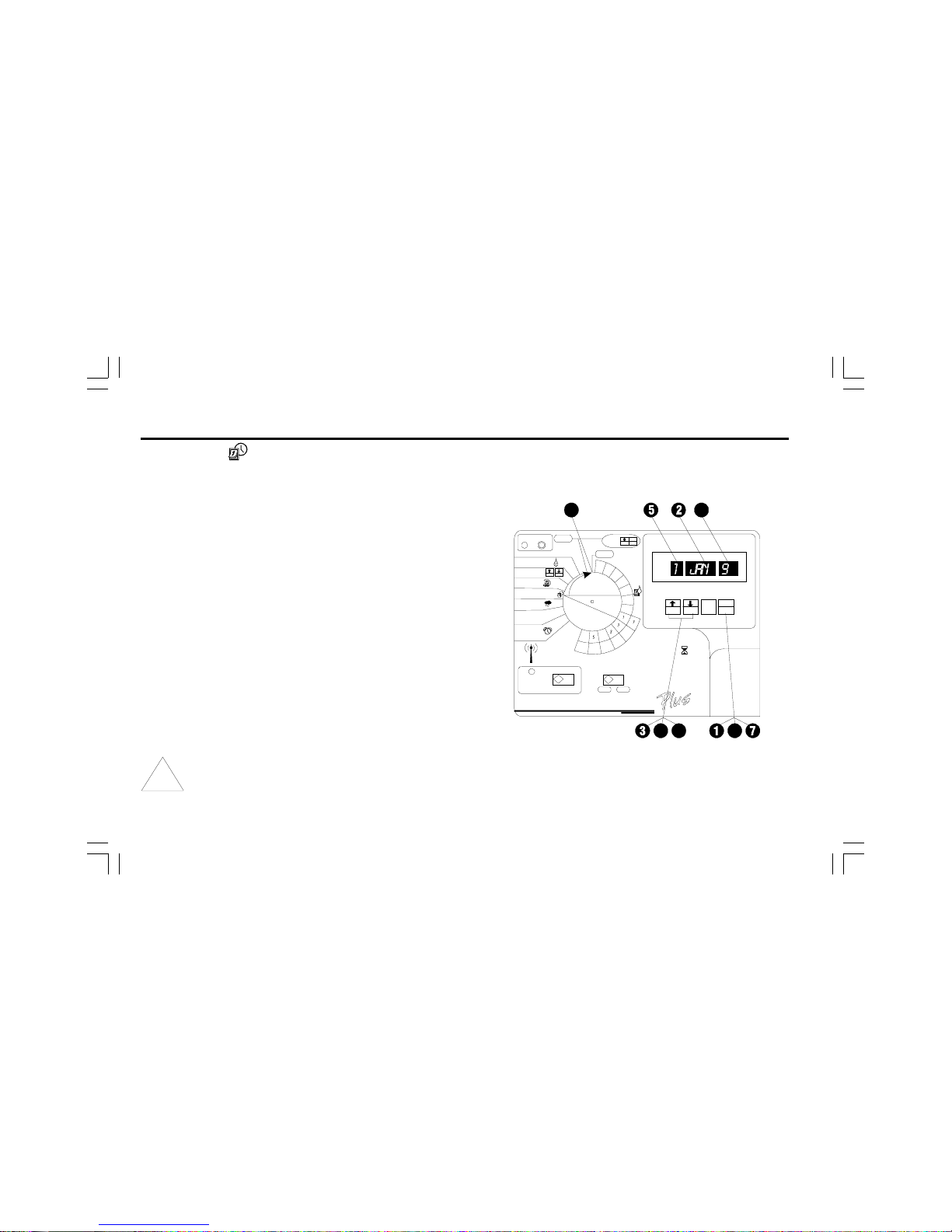
Set Date
➊ Press MAN. START/ADV. until the date (1/JAN/95) shows
in the display.
➋ The month flashes in the display.
➌ Press ñ or ò to set the current month.
➍ Press MAN. START/ADV.
➎ The day number flashes in the display.
➏ Press ñ or ò to set the current day of the month.
➐ Press MAN. START/ADV.
➑ The year flashes in the display.
➒ Press ñ or ò to set the current year.
➓ You are finished setting the time and date. Turn the dial to
AUTO.
NOTE: If you do not want to water on a specific day of
the month or on the 31st of any month, see Set
Calendar Days OFF on page 29.
Page 16
13ESP-LX+ & LXi+ Installation, Programming, & Operation Guide
Programs A, B, and C are not allowed to overlap each other. If
they are programmed to overlap, programs A, B, or C will
stack (run in consecutive order upon the completion of the
program in progress).
Program stacking prevents excessive flow demand and low
water pressure caused by having too many valves running at
one time.
NOTE: It is easier to select one program and program
it completely. Jumping from program to program can
be confusing.
Select Program
Four independent programs are available in the ESP-LX+,
LXi+ Series controller: A, B, C, and D-drip. Multiple independent programs let you enter watering schedules to meet the
requirements of different types of plant materials, soils, slopes,
shady or sunny areas, etc.
The D-drip program is designed for drip irrigation equipment.
Stations assigned to the D-drip program cannot be assigned
to any other program. The D-drip program can overlap, or run
concurrently, with programs A, B, or C.
➊ Turn the dial to AUTO.
➋ Press PGM to cycle through the available programs. The
program indicator on the far left side of the display shows
which program is currently selected.
Page 17
14 ESP-LX+ & LXi+ Installation, Programming, & Operation Guide
Set Watering Day Cycle
Each program can operate in one of four watering day cycles:
1. CUSTOM waters on the days of the week you select. See
the instructions below.
2. CYCLICAL waters on a selected daily interval (for example,
every other day, or every third day). See page 16.
3. ODD waters only on odd-numbered days of the month.
See page 18.
4. EVEN waters only on even-numbered days of the month.
See page 18.
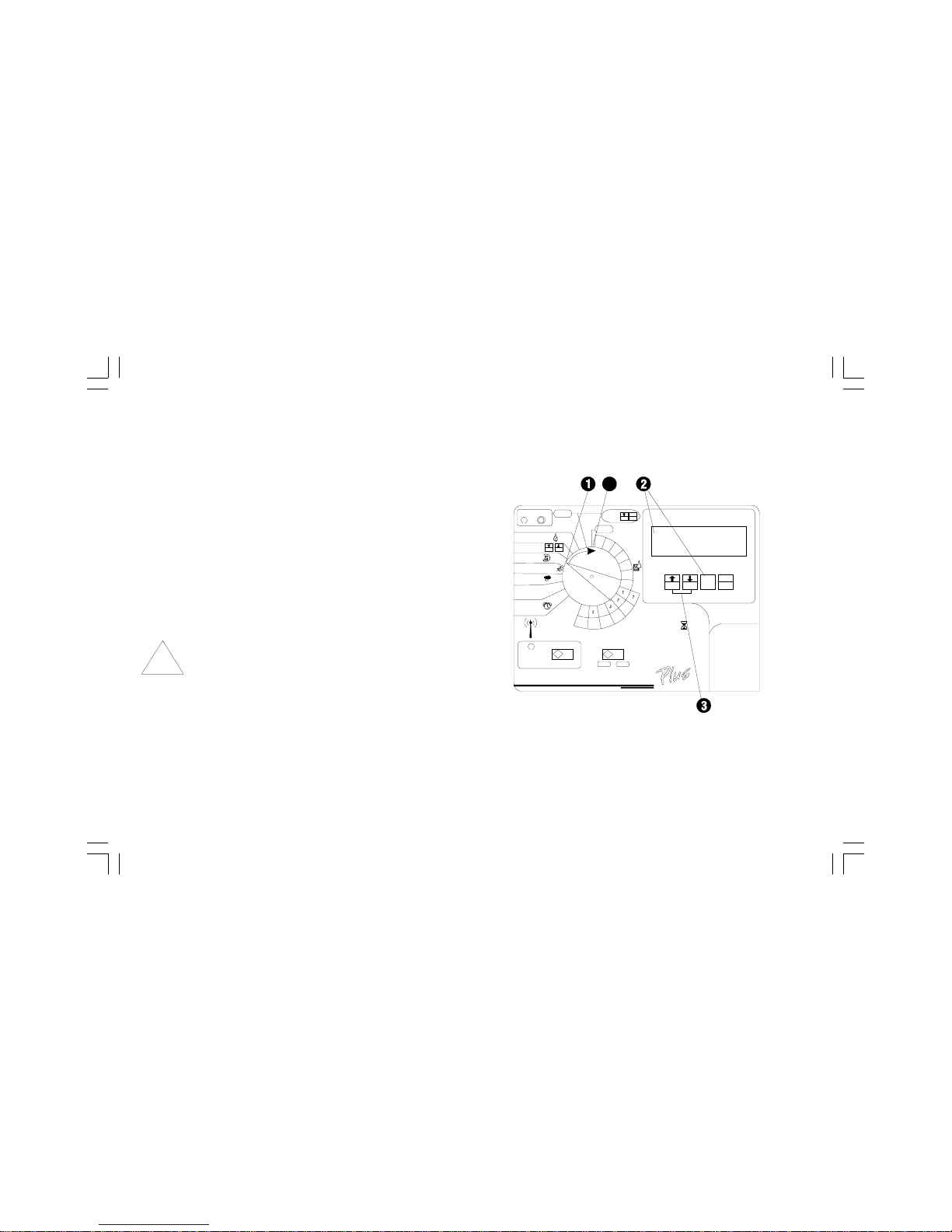
Custom
To set a custom cycle:
➊ Turn the dial to DAY CYCLE.
➋ The display shows the currently selected program. If the
program you want is not displayed, press PGM until it
appears.
➌ Press ñ or ò until CUSTOM appears in the display.
Page 18
15ESP-LX+ & LXi+ Installation, Programming, & Operation Guide
➍ Turn the dial to MON.
➎ The display shows the selected day and either ON or
OFF. ON means the selected day is a watering day. OFF
means watering doesnt take place on that day.
➏ Press ñ or ò to set the day ON or OFF.
➐ Turn the dial to the next day of the week. Repeat steps 5 and
6 until you have set each day of the week ON or OFF.
➑ Turn the dial to AUTO.
Page 19
16 ESP-LX+ & LXi+ Installation, Programming, & Operation Guide
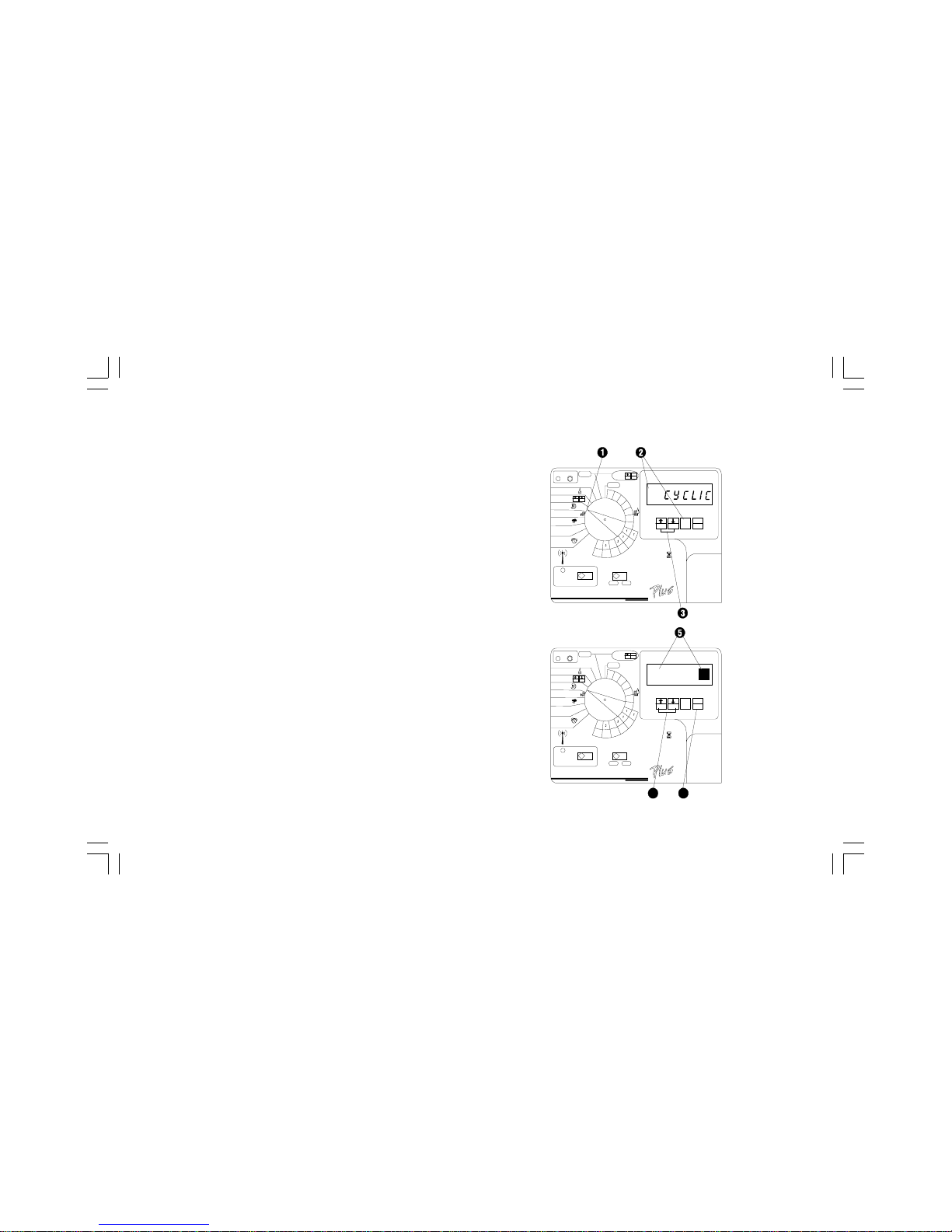
Cyclical
To set a cyclical schedule:
➊ Turn the dial to DAY CYCLE.
➋ The display shows the currently selected program. If the
program you want is not displayed, press PGM until it
appears.
➌ Press ñ or ò until CYCLIC appears in the display.
➍ Press MAN. START/ADV.
➎ The display shows the number of days remaining until a
watering day and the number of days in the cycle. The DAY
CYCLE digit flashes.
➏ Press ñ or ò to set the number of days in the cycle. For
example, if you want to water every other day, set the day
cycle to 2. If you want to water every third day, set the day
cycle to 3.
Page 20
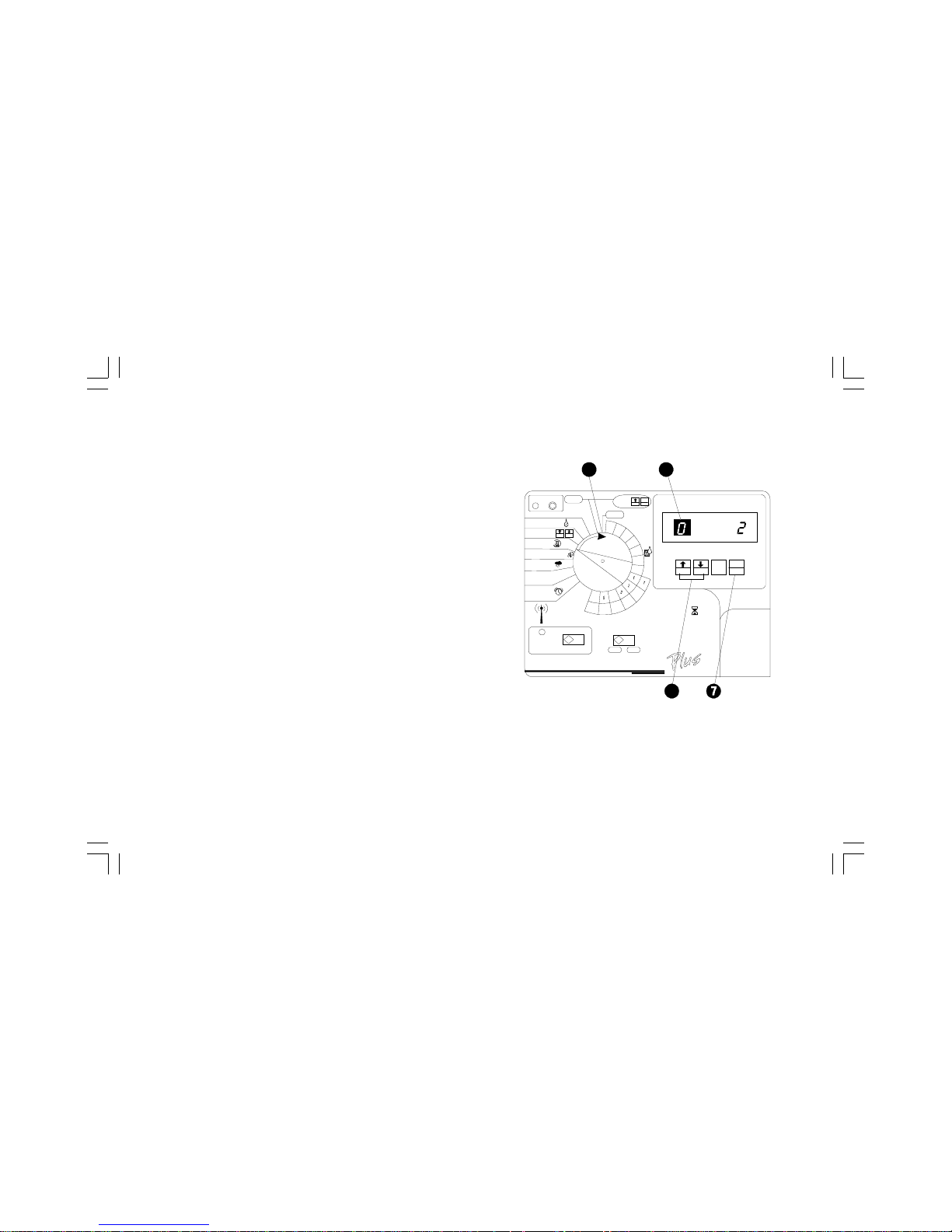
17ESP-LX+ & LXi+ Installation, Programming, & Operation Guide
➐ Press MAN. START/ADV.
➑ The DAYS REMAINING digit flashes.
➒ Press ñ or ò to set the number of days remaining before
the next watering day. 0 means that today is a watering
day. So if you want watering to begin tomorrow, set the days
remaining to1.
➓ Turn the dial to AUTO.
Page 21
18 ESP-LX+ & LXi+ Installation, Programming, & Operation Guide
Odd/Even Cycle
To set an odd/even cycle:
➊ Turn the dial to DAY CYCLE.
➋ The display shows the currently selected program. If the
program you want is not displayed, press PGM until it
appears.
➌ Press ñ or ò until ODD or EVEN appears in the
display.
➍ Turn the dial to AUTO.
NOTE: If you do not want to water on the 31st of any
month (a restriction imposed in some local areas), you
must set the 31st day OFF. See page 29 for
instructions.
Page 22
19ESP-LX+ & LXi+ Installation, Programming, & Operation Guide
Set Station Watering Times
You can set any station to run from 0 to 12 hours. For the first
two hours, you can set the watering time in one-minute increments. For the remaining 10 hours, you can set the watering
time in 10-minute increments.
➊ On 12-, 16-, 20-, and 24-station models, set the STA-
TIONS slide switch to the block of stations you want to set.
➋ Turn the dial to the station number you want in the
WATERING TIME PER STATION section of the dial.
➌ The display shows the program, the station number, and
the currently set watering time. If the station has been
included in another program, USED appears in the
display.
NOTE: If USED appears, you can still set a watering
time for the station unless the station has been
previously assigned to the D-drip program. Stations
assigned to the D-drip program cannot be used by
any other program.
Page 23

20 ESP-LX+ & LXi+ Installation, Programming, & Operation Guide
➍ If the program you want is not displayed, press PGM
until it appears.
➎ Press ñ or ò to set the length of time you want the
station to run. Repeat steps 2 - 5 for all stations. If you do
not want to include a station in the program, set the run time
to zero.
➏ After you have set the run time for the last station, turn the
dial to AUTO.
NOTE: You can use the Water Budgeting feature to
set watering times of less than one minute. For
example, if you set a station watering time of one
minute and adjust Water Budgeting to 50 percent,
the station will run for 30 seconds. See page 23 for
instructions on setting the Water Budget.
Page 24

21ESP-LX+ & LXi+ Installation, Programming, & Operation Guide
Set Program Start Times
You may assign up to six start times to each program per day.
A program may start on any quarter hour. Multiple start times
let you run a program more than once on each watering day.
For example if you are growing new lawn seed, you may want
to water several times a day to keep the seedbed or top
dressing damp.
NOTE: Start times apply to the entire program, not to
an individual station.
➊ Turn the dial to PROGRAM START TIMES.
➋ The display shows the program, the number of the start
time, and the start time itself. The start time number flashes.
➌ If the program you want is not displayed, press PGM until
it appears.
➍ Press ñ or ò to select one of the six start time numbers
for the program.
➎ Press MAN. START/ADV.
➏ The program start time flashes.
Page 25

22 ESP-LX+ & LXi+ Installation, Programming, & Operation Guide
➐ Press ñ or ò to set the start time. Start times are
available in 15-minute intervals throughout the day.
To eliminate a start time, leave the dial on PROGRAM START
TIMES. Choose the start time to be deleted and push MAN.
START / ADVANCE until the time flashes. Then press the ñ or
ò buttons until the LCD displays the OFF setting, located
between 11:45 p.m. and 12:00 a.m. (between 23:45 and 24:00
for International models).
NOTE: Start times appear in chronological order. If you
delete a start time by setting it to OFF, all later start
times are automatically moved down one start time
number.
When you set a start time for any start time number,
the controller automatically reorganizes the start times
so they appear in chronological order. The earliest
start time will be number 1, and the latest start time will
be number 6. This reorganizing only occurs after you
move the dial off the PROGRAM START TIMES
position.
➑ If you want to set additional start times, press MAN.
START/ ADV. Repeat steps 2 - 7 to set the next start time.
➒ Turn the dial to AUTO.
Page 26

23ESP-LX+ & LXi+ Installation, Programming, & Operation Guide
Set Water Budget
The water budget feature lets you increase or decrease the run
times of all stations on each program by a selected percentage.
You can set the percentage from 0 to 300, in increments of one
percentage point. Each program (A, B, C, and D) can have a
different water budget percentage.
You can use the water budget feature to cut back watering
during cool winter months, or to increase watering during
periods of unusual heat.
In addition, you can use the 0% setting to shut off a program
temporarily.
Water budget percentages are calculated based on the
normal programmed run times for each station. For example, if
a station is programmed to run for 10 minutes, and you set the
water budget to 80%, the station will run for 8 minutes (80% of
10). If you set the water budget to 120%, that same station will
run for 12 minutes (120% of 10).
➊ Turn the dial to WATER BUDGET.
➋ The display shows the selected program and its current
water budget percentage. The default is 100%.
➌ If the program you want is not displayed, press PGM
until it appears.
➍ Press ñ or ò to set the percentage.
➎ To set water budgeting for another program, press PGM
until the program appears. Then repeat step4.
➏ Turn the dial to AUTO. When the water budget for a
program is set higher or lower than 100%, WATER
BUDGET appears in the display whenever the program is
selected.
Page 27

24 ESP-LX+ & LXi+ Installation, Programming, & Operation Guide
Set Station Delays
The station delay feature lets you program a pause between
the end of one stations watering operation and the beginning
of the next stations operation. You may set a delay from one
second to nine hours.
You can use station delays to let a water well recover or to
allow slow-closing valves to turn off completely. If neither of
these situations applies to your site, leave the station delay set
to 0.
You can set a different station delay for each program. A
station delay applies to all stations on a given program.
Because the station delay feature is not used very often, it has
been hidden behind the TEST / STATION DELAY position
on the dial.
➊ Turn the dial to TEST / STATION DELAY.
➋ The display shows TEST and the standard two-minute
run time for the test program.
➌ Press ñ AND ò at the same time.
Page 28

25ESP-LX+ & LXi+ Installation, Programming, & Operation Guide
➍ DELAY appears in the display momentarily, followed by
the delay time.
➎ If the program you want is not displayed, press PGM
until it appears.
➏ Press ñ or ò to set the delay time. To cancel station
delay, set the delay time to zero.
NOTE: The display initially shows the delay time in
seconds (SEC). When you advance past 59
seconds, the display changes to MIN for minutes
and seconds. When you advance past 60 minutes,
the display changes to HOUR for hours and
minutes.
➐ To set delays for additional programs, press PGM until the
program you want appears. Repeat step 6.
➑ Turn the dial to AUTO.
NOTE: During the delay between stations, the
master valve / pump relay is not active. See page 26
for instructions on setting the master valve / pump
relay.
Page 29

26 ESP-LX+ & LXi+ Installation, Programming, & Operation Guide
The MV / Pump start setting affects the station in all programs
to which it is assigned.
CAUTION: If an unused station is turned on and
activates a pump start relay, the pump may overheat
or cause a pipe to burst. To prevent operating a pump
with no flow (deadheading), make sure all unused
stations have a zero run time.
Set MV / Pump Starts
You can assign a master valve relay or a pump start relay to
each station. This means that any time the station operates, the
relay assigned to it will also turn on. For example, if a specific
station needs additional water pressure, you may want to
activate a booster pump whenever that station turns on.
NOTE: Stations that have a master valve / pump
relay assigned to them must be wired properly to
activate the relay. See pages 53-55 for instructions.
➊ Turn the dial to MV or PUMP SELECT.
➋ The display shows the station number and MV ON or
MV OFF. The station number flashes.
➌ Press ñ or ò to select the station number you want to
set.
➍ Press MAN. START/ADV.
Page 30

27ESP-LX+ & LXi+ Installation, Programming, & Operation Guide
➎ The ON or OFF flashes in the display.
➏ Press ñ for ON or ò for OFF.
➐ To set another station, press MAN. START/ADV. Repeat
steps 2 - 6 for each station you want to set.
➑ Turn the dial to AUTO.
Page 31

28 ESP-LX+ & LXi+ Installation, Programming, & Operation Guide
Set Rain Delay
ESP-LX+ and -LXi+ controllers let you manually delay
watering for up to 14 days. For example, if rainy weather lasts
for 2 or 3 days, you can set a Rain Delay of 5 or 6 days to let the
landscape dry out before resuming normal watering.
The Rain Delay setting applies to all programs. You can run
programs manually during the Rain Delay period.
NOTE: The Rain Delay feature lets you set a delay
period manually. If you have an automatic rain sensor
attached to your system, see the instructions on
page 31.
➊ Turn the dial to RAIN DELAY.
➋ The display shows RAIN DELAY and the number of days
remaining until the next watering day. If there is no Rain
Delay set, zero will appear in the display above the words
DAYS REMAINING.
➌ Press ñ or ò to set the number of days to wait until the
next watering day. To cancel a Rain Delay, set the number
of days to zero.
➍ Turn the dial to AUTO.
Page 32

29ESP-LX+ & LXi+ Installation, Programming, & Operation Guide
Set Calendar Days OFF
The Calendar Day OFF feature lets you:
• Temporarily suspend watering on a specific day of the
month (selected up to 30 days in advance). For example, if
you are planning a picnic on July 4th, you can set July 4th
OFF, so no watering will occur. After July 4th passes, the
fourth of each month will be automatically reset to ON.
• Permanently set the 31st day of any month OFF. This setting
complies with local watering ordinances that prohibit watering
on the 31st. Unlike settings for other days of the month, this
setting remains in effect until you change it.
A Calendar Day OFF setting applies to all programs.
➊ Turn the dial to TIME & CALENDAR.
➋ Press MAN. START/ADV five times.
➌ The display shows the day of the month and its ON or OFF
setting. The day of the month flashes.
➍ Press ñ or ò to select the day of the month you want to
set.
Page 33

30 ESP-LX+ & LXi+ Installation, Programming, & Operation Guide
➎ Press MAN. START/ADV.
➏ The ON or OFF setting flashes.
➐ Press ñ to set the day ON or ò to set the day OFF.
➑ Turn the dial to AUTO. When an OFF day occurs, the
display shows NON (for non-watering day), and no
watering occurs. The next time the date occurs, normal
watering schedules will resume (except for the 31st of the
month, which remains OFF until you reset it manually).
Page 34

31ESP-LX+ & LXi+ Installation, Programming, & Operation Guide
NOTE: For this feature to operate properly, the sensor
must be connected according to the instructions on
page 54.
➊ To activate the sensor system, set the sensor bypass
switch to ACTIVE. The controller will operate normally
until a wet condition is detected by the sensor.
NOTE: If no sensor is attached to the controller, make
sure the supplied jumper connects the two SENSOR
terminals on the controllers circuit board. If you set
the sensor bypass switch to ACTIVE without a
sensor or jumper connected to these terminals, the
valves will not operate, and no watering will occur. See
page 54 for instructions.
➋ When the sensor detects a wet condition, power to the
valves will be interrupted, and no watering will occur
(including manual program or station operation.) The
WATERING SUSPENDED BY SENSOR indicator will light
up.
Set Sensor System and Bypass
Switch
ESP-LX+ and -LXi+ controllers let you connect a sensor
system that interrupts watering when a wet condition is
detected. For example, if you have a Rain Bird Rain Check
sensor connected to the controller, irrigation will be prevented
when rainfall reaches the shutoff level in the sensors collector
cup.
Page 35

32 ESP-LX+ & LXi+ Installation, Programming, & Operation Guide
➌ To bypass the sensor, set the sensor bypass switch to
OFF. The controller will ignore any sensor signals, and
normal watering schedules will resume. This setting
also lets you run programs and stations manually.
Page 36

33ESP-LX+ & LXi+ Installation, Programming, & Operation Guide
OPERATING THE CONTROLLER
After you have programmed the controller, you will normally set
it to operate automatically.
You can also manually run one or more programs, and you can
manually operate a single station or several stations.
In addition, you can run a test program to test the operation of
all stations on the system. To operate automatically, run
programs or stations manually, or run a test program, the
controller should be connected to a 120 volt AC power source
(230 volt AC for international models).
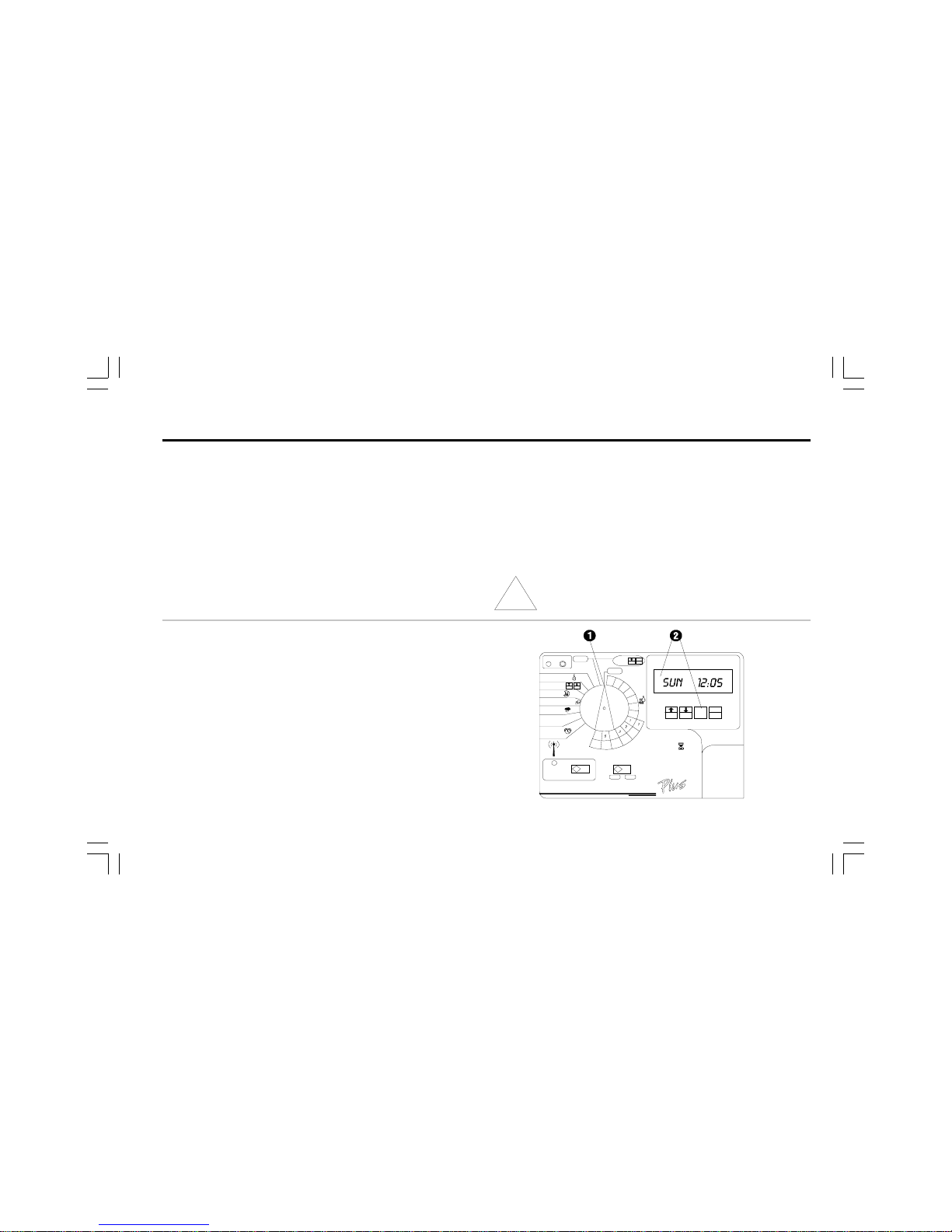
Operate Controller Automatically
➊ Turn the dial to AUTO. The controller runs the sprinklers
according to the programs you have set.
If you forget to turn the dial to AUTO, the controller will
eventually set itself to automatic operation. The only
setting that prevents automatic operation is OFF
(see step 2).
➋ To turn off the controller and prevent all watering, turn the
program dial to OFF. The display will show the current
day and time, and the right-hand minute digit will flash,
indicating that the controller has been turned off.
You can use the OFF setting to suspend watering during
rainy periods, seasonal shutdown, or system maintenance.
Page 37

34 ESP-LX+ & LXi+ Installation, Programming, & Operation Guide
Run Program(s) Manually
NOTE: To run a program manually, please follow the
instructions below carefully. Unlike other ESP
controllers, ESP-LX+ and -LXi+ controllers have
completely independent programs. Therefore, you
must select a program before you press the MAN.
START / ADV. button.
➊ Turn the dial to AUTO.
➋ The display shows the day of the week and time of day.
➌ Press PGM until the program you want is displayed.
➍ Press MAN. START / ADV. to start the selected program.
If you want to run additional programs, repeat steps 3 and
4. Each program you select will run when the previous
program has ended. You can stack all four programs to
run in sequence.
➎ To cancel all programs currently selected to run, turn the
dial to OFF for three seconds. Then turn the dial back to
AUTO.
Page 38

35ESP-LX+ & LXi+ Installation, Programming, & Operation Guide
Run Station(s) Manually
➊ On 12-, 16-, 20-, and 24-station models, set the
STATIONS slide switch to the block of stations
containing the one you want to run.
➋ Turn the dial to the station number you want in the
WATERING TIME PER STATION section of the dial.
➌ The display shows the currently selected program, the
station number, and the stations run time. If the station is
not used in the current program but is used in another
program, the word USED will appear in the display
instead of the run time.
➍ Press PGM until the display shows a run time for the
station.
➎ Press MAN. START / ADV. to operate the selected
station. If you want to run additional stations, repeat steps
3 to 5. Each station you select will run when the previous
station has ended.
➏ After selecting all the stations you want to run, turn the dial
to AUTO. The stations you have selected will operate for
their programmed run times and then shut off automatically.
➐ To cancel the manual operation of all selected stations, turn
the dial to OFF for three seconds. Then turn the dial back
to AUTO.
Page 39

36 ESP-LX+ & LXi+ Installation, Programming, & Operation Guide
Run Test Program
The controllers built-in test program will run each station that
has a non-zero watering time assigned to it. When you run the
test program, the controller will operate each station in
numerical sequence, from lowest to highest. You can use this
program to check the operation of all the sprinklers in the
system.
➊ Turn the dial to TEST/ Station Delay.
➋ The display shows TEST and the amount of time each
station will run. The default test run time is two minutes per
station.
➌ Press ñ or ò to increase or decrease the run times for
the TEST PROGRAM. The maximum test run time is 10
minutes.
➍ Press MAN. START/ADV. to start the test program.
➎ Turn the dial to AUTO.
➏ The display shows the number of the station that is
running, along with its remaining run time. The controller
runs each station in sequence, from lowest number to
highest. The test program skips any stations that have
zero watering times assigned to them. When the test
program is finished, the controller returns to automatic
operation.
➐ To cancel a test program after it has started, turn the dial
to OFF for three seconds. Then turn the dial back to
AUTO.
Page 40

37ESP-LX+ & LXi+ Installation, Programming, & Operation Guide
RAPID STATION TEST ROUTINE RASTER
The RASTER is available on indoor and outdoor versions of
Rain Birds ESP-LX+ and -LXi+ controllers.
Introduction
Rain Birds RApid Station TEst Routine (RASTER) lets you
diagnose and troubleshoot field wiring, solenoid, and controller
problems quickly and easily.
The RASTER sends an electric signal to each valve terminal on
the controller and then displays the valves current operating
condition. Results appear in the easy-to-read digital display.
The RASTER checks each station and displays one of three
results:
1. OPEN The circuit between the controller and the valve
is open; i.e., no current is flowing.
2. SHORT The circuit between the controller and the valve
has a short; i.e., current is flowing on an
unintended path.
3. FAIL The controller was unable to send the test signal
to the stations. This indicates a possible
problem with the controllers internal circuitry.
Page 41

38 ESP-LX+ & LXi+ Installation, Programming, & Operation Guide
RASTER Operation
Running a RASTER
(Rapid Station Test Routine)
NOTE: To run the RASTER, the controller must be
connected to a 120 Volt AC power source
(230 Volt for international models).
➊ Turn the Programming Dial to OFF.
➋ Press and release the ON and OFF buttons at the same
time.
➌ The display will look like this.
Page 42

39ESP-LX+ & LXi+ Installation, Programming, & Operation Guide
Press the MAN START/ADV button to begin the RASTER.
➎ The display shows TEST IO, and the FAULT Indicator
light flashes once as the RASTER confirms the proper
operation of the controllers front panel lights.
The RASTER then automatically checks the controllers
master valve and each station valve (in numerical order).
NOTE: If the front panel ribbon cable is not connected
to the circuit board or the controller is disconnected
from the main power supply, the LCD will display the
message NO OUT.
TEST IO
Page 43

40 ESP-LX+ & LXi+ Installation, Programming, & Operation Guide
Valve Testing
➊ The display briefly shows TEST (may flash too rapidly to
be seen) and the station number (or MV for master
valve) being tested.
➋ The display shows the valves operating condition
(PASS, FAIL, OPEN, or SHORT), followed by the
station number (up to 24 stations, depending on controller
model). This sample display indicates a short on valve
station number 4.
➌ The RASTER displays the condition of each valve for 10
seconds, (PASS displays for less than one second and
may flash too fast to be seen) and then moves to the next
valve. You can press MAN START/ADV (or any other
magenta button) at any time to advance to the next station
to be tested.
NOTE: Any controller station that does not have a valve
connected to it will appear as OPEN. This is normal
and does not indicate any problem with the controller
or system valves.
For example, if you have a 12-station controller with
only stations 1 through 10 connected to valves,
stations 11 and 12 will show OPEN on the RASTER.
Page 44

41ESP-LX+ & LXi+ Installation, Programming, & Operation Guide
➍ If the master valve and all station valves pass the RASTER,
the display flashes PASS for 10 seconds. The controller
then returns to normal operation (i.e., waiting for its next
start time).
NOTE: If any unconnected valve station caused the
RASTER to display an OPEN message, (see NOTE on
previous page), the PASS message will not be
displayed. This is normal and does not indicate any
problem with the controller or the valves.
➎ If the RASTER detects a problem on the master valve or
any station valve, the display flashes CHECK for three
seconds.
➏ The display shows the condition and number of each
problem station. Each problem station will flash in the
display for five seconds. Press MAN START/ADV at any
time to display the next problem station.
➐ If any station displays FAIL, it means the controller was
unable to send the test signal to the valve, indicating a
possible problem with the controllers internal circuitry. Call
Rain Bird Technical Assistance at 800-247-3782, or contact
your local authorized Rain Bird distributor to service your
controller.
Page 45

42 ESP-LX+ & LXi+ Installation, Programming, & Operation Guide
➑ Any valve displaying OPEN or SHORT should be
checked for field wiring or other circuit problems. See
Troubleshooting Open and Shorted Valves Circuits on
page 43 for more information.
➒ To exit the RASTER, turn the Programming Dial from OFF
to AUTO (or any other dial position).
➓ The controller returns to normal operation, awaiting its
next scheduled start time.
Page 46

43ESP-LX+ & LXi+ Installation, Programming, & Operation Guide
Open Circuits
An OPEN condition reported by the RASTER indicates a
complete break in the current flow between the controller and
the valve.
NOTE: The RASTER will display an OPEN condition if
no valve solenoid is connected to the controller
station. This is normal, and the system does not need
service.
Open circuits can be caused by:
• Malfunctioning valve solenoids
• Field wires that have been cut or pulled loose
• Loose wire connections on the controllers terminal strip or
at the valve solenoid
• Damaged components on the controllers internal circuit
board
Troubleshooting Open and Shorted Valve Circuits
Page 47

44 ESP-LX+ & LXi+ Installation, Programming, & Operation Guide
Short Circuits
A SHORT condition reported by the RASTER indicates an
unintended re-routing of current flow somewhere between the
controller and the valve.
Short circuits can be caused by:
• Shorted valve solenoids
• Nicked or skinned field wires
➌ If the OPEN or SHORT recurs on the original station,
the controllers internal circuitry may need service.
➍ If the OPEN or SHORT moves to the new station, check
the valves solenoid and field wiring.
• Loose or corroded wire connections on the controllers
terminal strip or at the valve solenoid
• Malfunctioning components on the controllers internal
circuit board
Troubleshooting Opens and Shorts
To troubleshoot a valve station identified as OPEN or
SHORT:
➊ Make sure the valves station wires are securely connected
to the controllers terminal strip.
➋ If the wires are securely connected, move the stations wires
to a station that passed the RASTER. Then re-start the test.
Page 48

45ESP-LX+ & LXi+ Installation, Programming, & Operation Guide
INSTALLING THE CONTROLLER
This section of the manual explains how to mount the controller
on the wall and connect the wiring.
NOTE: This controller must be installed in compliance
with local electrical codes.
The ESP-LXi+ controller must be installed indoors only. The i
in the model number stands for indoors.
The ESP-LX+ controller may be installed either indoors or
outdoors.
Installation Checklist
To install the ESP-LX+ controller, we recommend that you
complete the following steps in order. For your convenience, a
check-off box (❐) is provided for each step.
❐ Select location. ...................................................................... Page 46
❐ Remove door and face panel. . ............................................. Page 48
❐ Mount controller on wall. . ...................................................... Page 50
❐ Connect field wires. . ............................................................. Page 52
❐ Connect sensor system (optional). . ...................................... Page 54
❐ Connect main power wires. . ................................................. Page 56
❐ Install battery. . ....................................................................... Page 62
Page 49

46 ESP-LX+ & LXi+ Installation, Programming, & Operation Guide
Select Location
Follow these guidelines to select a location for the controller:
➊ Select an area protected from vandalism, where the user
can easily reach the controller. We recommend mounting
the controller at eye level in a utility room.
NOTE: To minimize electromagnetic interference,
select a location at least 15 feet (4,6 m) away from
high-draw motors such as air conditioners,
refrigerators, or pool pumps.
➋ Select a location that has access to 120-Volt AC electrical
power or 230-Volt AC electrical power (as required).
WARNING: A circuit breaker or cutoff switch is to be
provided in the fixed wiring to isolate the controller.
➌ Choose a flat, stable, vertical surface. Allow enough
clearance for electrical conduit and connections at the
bottom of the plastic cabinet.
➍ Allow at least 9½" (24,2 cm) of horizontal clearance so the
hinged cabinet door can swing fully open to the left.
➎ Allow at least 6¾" (17,2 cm) of clearance above the
cabinet door so the hinge pin can be removed to service
the controller.
Page 50

47ESP-LX+ & LXi+ Installation, Programming, & Operation Guide
Page 51

48 ESP-LX+ & LXi+ Installation, Programming, & Operation Guide
Remove Door and Face Panel
Before you mount the controller, we recommend that you
remove the door and face panel. Although these steps are not
absolutely necessary, they will make installation more convenient.
➊ Open the door and swing it to the left. If necessary, unlock
the door with the supplied key.
➋ Flip the upper tip of the hinge pin out of the groove in the
door so it is pointing at you.
➌ Support the door and slide the hinge pin upward until it
clears the hinges. Then remove the door.
➍ Open the face panel by grasping its lower right corner and
swinging it to the left.
➎ Disconnect the ribbon cable by grasping it along its two
flat sides. Then pull the cable gently out of its connector.
➏ Unplug the two-wire harness by releasing the latch on the
side of the connector. Then pull the connector away from
the terminal board.
➐ Press down on the upper flexible hinge to release the
hinge knob from its hole in the cabinet.
➑ Pull the lower hinge knob out of its hole and remove the
panel.
To reconnect the face panel and door, repeat the steps above
in reverse order. Make sure to reconnect the ribbon cable and
two-wire harness to their connectors for proper controller
operation.
Page 52

49ESP-LX+ & LXi+ Installation, Programming, & Operation Guide
Page 53

50 ESP-LX+ & LXi+ Installation, Programming, & Operation Guide
Mount Controller on Wall
The ESP-LX+ has four mounting holes on the back of the
cabinet three keyhole slots at the top of the cabinet and one
circular hole at the bottom of the cabinet. The shipping carton
for the controller contains a mounting template. You may wish to
cut this template out and use it to mark the controllers mounting
holes in the desired location before you begin drilling.
➊ To install the controller on a flat wall surface, use the left and
right keyhole slots at the top of the cabinet.
➋ To install the controller on a narrow stud, use the center
keyhole slot.
➌ For all installations, use the small round hole at the bottom
of the cabinet.
➍ Hold the controller or mounting template at eye level against
the mounting surface. Use a pencil to mark the position of
the holes on the mounting surface. Then remove the
controller cabinet or template.
➎ On flat wall surfaces, drive an appropriate fastener for the
type of wall into the two outside keyhole marks.
➏ For narrow stud installations, drive an appropriate fastener
for the type of wall into the middle keyhole mark.
➐ Use a nail to tap a small pilot hole on the mark for the
lower mounting hole. However, DO NOT drive a fastener
into this location yet.
➑ Use the keyhole slot(s) to hang the controller cabinet on
the fasteners. Make sure the shafts of the fasteners are well
up in the narrow part of the keyholes.
➒ Drive the last fastener through the lower mounting hole.
Verify that the cabinet is secure. If necessary, tighten the
fasteners in the upper keyhole slot(s).
Page 54

51ESP-LX+ & LXi+ Installation, Programming, & Operation Guide
COM COMMV
GND
MV11
9
9
2
2
10
10
3
3
11
11
4
4
12
12
5
5
13
13
6
6
14
14
7
7
15
15
8
8
16
16
24
VAC
SENSOR
#
"
!
$
%
COM COMMV
GND
MV11
9
9
2
2
10
10
3
3
11
11
4
4
12
12
5
5
13
13
6
6
14
14
7
7
15
15
8
8
16
16
24
VAC
SENSOR
&
'
Page 55

52 ESP-LX+ & LXi+ Installation, Programming, & Operation Guide
Connect Field Wires
Field Wire Entrances
The ESP-LX+ cabinet has four knockouts for routing field wires
from the valves. Two are located on the underside of the cabinet,
and two are located on the back of the cabinet.
➊ The underside of the cabinet has a hole sized for a 1"
(2,6 cm) PVC male adapter so you can easily install a
1" (2,6 cm) PVC pipe or conduit for the valve wires.
➋ A larger knockout for a 1¼" (3,2 cm) PVC male adapter is
molded into the underside of the cabinet, surrounding the
hole for the 1" (2,6 cm) PVC adapter. You may need this
larger hole if you are using #14 gauge wire or larger.
To use the larger hole, turn the cabinet upside down. Place
the blade of a slot-head screwdriver in the groove around
the knockout. Then firmly tap the handle of the screwdriver
to punch in the knockout. You may need to punch the
groove in two places.
➌ If you wish to route the field wires through the wall on which
the controller is mounted, use the knockout for the 1"
(2,6cm) PVC adapter on the back of the controller cabinet.
Use a screwdriver to punch out the knockout, as described
in step 2.
Page 56

53ESP-LX+ & LXi+ Installation, Programming, & Operation Guide
Station Valve Wiring
Connect each valve by its own separate power wire to one of
the numbered terminals on the ESP-LX+ terminal strip, as
shown in the illustration. You may connect up to two 24 VAC,
7VA solenoid valves per station. You may use the special Valve
Test position to help identify valve stations BUT NOT for
permanent connections.
To speed up installation, slide the stripped end of the valve
wire under the pinch plate at each terminal. The pinch plate
eliminates the need to wrap the wire around the screw head.
NOTE: The ESP-LX+ 20- and 24-station models have
a special screwless terminal strip for valve wire
connections.
Connect a common wire to one of the leads on each valve.
Connect the other end of the common wire to the COM terminal
on the flip strip. Wire used to connect the valves must be codeapproved for underground installation.
Master Valve Wiring
NOTE: Complete this section only if your system
requires a master valve (an automatic valve installed
on the mainline pipe upstream from the station valves)
or a pump relay. The controller does NOT provide
main power for a pump. Connect the master valve
wiring to the MV terminal and COM terminal as
shown in the illustration.
Page 57

54 ESP-LX+ & LXi+ Installation, Programming, & Operation Guide
Sensor System Wiring
NOTE: Complete this section only if your system has
an automatic rain sensor.
If you are not connecting a sensor to the controller,
make sure the supplied jumper is installed on the
two SENSOR terminals on the controllers vertical
terminal strip.
➊ Most sensors have two wires or two terminals designed to
be connected to the valve common wire. Instead of
connecting to the valve common wire, connect these wires
or terminals to the SENSOR terminals on the ESP-LX+ or
LXi+ controller.
➋ Route the pair of wires out of the controller cabinet to the
sensor system.
➌ Follow the sensor systems directions for placing and
connecting moisture probes, setting the rain shutoff level,
and making final adjustments.
Page 58

55ESP-LX+ & LXi+ Installation, Programming, & Operation Guide
Pump Start Relay Wiring
NOTE: Complete this section only if your system
requires a pump start relay.
The MV terminal on the controllers terminal strip can be
used to connect a pump start relay. Connect one lead of the
24VAC pump start relay to the MV terminal and the other
lead to the common wire, as shown in the illustration.
CAUTION:To prevent pump damage when using a
pump start relay, use a jumper wire to connect
any unused stations to a station that is being
used.
Page 59

56 ESP-LX+ & LXi+ Installation, Programming, & Operation Guide
WARNING: To prevent electrical shock, make sure all
supply power is OFF before connecting these wires.
Electrical shock can cause severe injury or death.
All electrical connections and wiring runs must be
made according to local building codes.
Connect Main Power Wires
ESP-LX+ (Outdoor / Indoor Controller)
NOTE: To connect main power wires on the
ESP-LXi+ indoor-only controller, see the instructions
on page60.
The ESP-LX+ controller has an internal transformer that
reduces standard supply voltage (117 VAC in U.S. models;
230 VAC in international models) to 24 VAC to operate the
valves connected to the controller. You will need to connect
power supply wires to the transformers three wires.
➊ With the door and face panel removed, locate the high-
voltage compartment in the lower left corner of the controller
cabinet.
➋ Remove the screw on the right edge of the compartment
cover. Then swing the cover open to expose the
transformers primary input wires.
Page 60

57ESP-LX+ & LXi+ Installation, Programming, & Operation Guide
➌ If you wish to bring the power supply wires through the
wall on which you mount the controller, use the ½"
(1,3cm) knockout in the rear of the cabinet. Also remove
the circular cutout in the flame-retardant fiberboard liner
at the rear of the high-voltage compartment. For safety
purposes, be sure to seal the unused entry at the bottom
of the cabinet.
➍ If you wish to bring the supply wires through the bottom of
the cabinet, attach a ½" (1,3cm) conduit fitting to the
bottom entrance of the high-voltage compartment. Then
attach conduit to the fitting.
Page 61

58 ESP-LX+ & LXi+ Installation, Programming, & Operation Guide
➎ Bring three supply wires from the power source through
the conduit into the high-voltage compartment. Strip the
insulation from the incoming wires to expose about ½"
(1,3cm) of bare wire.
➏ Using a code-approved wire connector, connect the wires
as follows:
• On 117-120 VAC models (U.S.), connect the black
supply wire (hot) to the black transformer wire.
• On 230 VAC models (international), connect the
brown supply wire (hot) to the brown transformer
wire.
➐ On 117-120 VAC models (U.S.), connect the white supply
wire (neutral) to the white transformer wire.
On 230 VAC models (international), connect the blue
supply wire (neutral) to the blue transformer wire.
➑ On 117-120 VAC models (U.S.), connect the green supply
wire (ground) to the green transformer wire.
On 230 VAC models (international), connect the greenwith-yellow-stripe supply wire (ground) to the greenwith-yellow-stripe transformer wire.
Page 62

59ESP-LX+ & LXi+ Installation, Programming, & Operation Guide
NOTE: The ground wires MUST be connected to
provide electrical surge protection.
➒ Verify that all connections are secure. Then close the
cover of the high-voltage compartment and secure it
with the screw.
COM COMMV
GND
MV11
9
9
2
2
10
10
3
3
11
11
4
4
12
12
5
5
13
13
6
6
14
14
7
7
15
15
8
8
16
16
24
VAC
SENSO R
CAUTION
HIGH
VOLTAGE
'
CAUTION
HIGH
VOLTAGE
Page 63

60 ESP-LX+ & LXi+ Installation, Programming, & Operation Guide
ESP-LXi+ (Indoor-Only Controller)
The ESP-LXi+ controller (117 VAC model only) has an external
transformer that reduces standard supply voltage to 24 VAC to
operate the valves connected to the controller.
You will need to connect the three wires from the transformer to
the vertical terminal strip in the controller cabinet.
CAUTION: To avoid electrical shock, do NOT plug in the
transformer until you have connected its cable to the
controller. If the transformer is plugged in while the
cable is not attached, any contact between the three
forked connectors will blow the transformers internal
fuse. A blown transformer fuse cannot be repaired.
All electrical connections and wiring runs must be
made according to local building codes.
➊ Make sure the transformer is NOT plugged in.
➋ Feed the three forked transformer wires through the
bottom left hole in the cabinet. Then pull about 12 inches
of the cable up into the controller cabinet.
➌ Tie a loose overhand knot in the cable just inside the
controller to prevent any strain on the connector terminals.
Page 64

61ESP-LX+ & LXi+ Installation, Programming, & Operation Guide
➍ On the vertical terminal strip, connect the green forked
wire to the terminal labeled GND.
NOTE: The green ground wire MUST be connected
properly to provide electrical surge protection.
➎ Snap open the protective cover and connect one of the
remaining two forked wires to one of the terminals labeled
24VAC. (In some units, these two terminals are labeled
ORN.) Connect the last forked wire to the other terminal
labeled 24VAC. Polarity of these two wires is not important. You may connect either wire to either terminal. Then
close the protective cover.
➏ Verify that all connections are secure. Then plug the
transformer into any standard three-prong grounded
117VAC electrical outlet.
CAUTION: To prevent electric shock, match the wide
blade of the plug to the wide slot, fully inserted.
cover
Protective
Page 65

62 ESP-LX+ & LXi+ Installation, Programming, & Operation Guide
Install Battery
The 9-Volt rechargeable nickel metal hydride (NiMH) battery
supplied with the controller provides power to maintain the
current time and date during a power outage. All program
information you have entered is maintained independently of
battery power. So if a prolonged power outage outlasts the life
of the battery, you will only have to update the time and date
after power is restored (your program is the default).
NOTE: Memory of the time and date is retained by a
battery which is to be disposed of in accordance
with local regulations.
The battery also lets you program the controller with the face
panel detached from the cabinet power supply.
➊ If you have removed the face panel and cabinet door for a
new installation, reinstall them now. Be sure to connect the
ribbon cable and two-wire harness from the face panel to
the controllers circuit board, as described on page 48.
➋ Loosen the screw on the battery cover, and slide the
battery out of its compartment. If you are replacing a used
battery, discard the old battery properly. The replacement
battery must be a 9-Volt rechargeable NiMH battery.
➌ If the battery has a protective cover installed over its
terminals, remove the cover. Then connect the two-wire
battery clip to the terminals.
Page 66

63ESP-LX+ & LXi+ Installation, Programming, & Operation Guide
➍ Slide the battery back into its compartment, and tighten
the screw.
➎ The controller will fully charge the supplied NiMH battery
in approximately 48 hours. The controller will continue to
trickle-charge the battery whenever the controller is supplied
with electrical power.
Page 67

64 ESP-LX+ & LXi+ Installation, Programming, & Operation Guide
Diagnostic Circuit Breaker
If the ESP-LX+ or ESP-LXi+ controller detects an electrical
short circuit on one of the sprinkler systems station wires or
valve solenoids, the controller automatically shuts off the
station with the fault. After shutting off the shorted station, the
controller advances to the next working station in the program.
Every three seconds, the LCD displays the problem stations
number and the message FAULT. The Fault LED will also flash,
indicating a station short circuit.
The controller will continue to run each operable station in the
program. As each station is running, the controller (at an
alternate 3-second interval) displays the working stations
number and run time remaining (when the programming dial is
set to the AUTO position).
When the controller finishes the program, it will continue to
display the problem stations number and the FAULT message
and the Fault LED will continue to flash.
After the program finishes, you should isolate and repair the
short circuit. Short circuits occur most frequently in the valve
solenoid (the plastic-encapsulated coil on the valve with the two
wire leads), or in the wire connectors to the valve leads.
After you find and repair the short circuit, press the Clear
Fault button to clear the FAULT message from the display
and stop the flashing Fault LED. Then you may wish to operate
the station manually to make sure it works properly. (See Run
Station(s) Manually on p. 35).
The LCD display shown below indicates that the controller has
detected a short circuit on station 2.
Page 68

65ESP-LX+ & LXi+ Installation, Programming, & Operation Guide
TROUBLESHOOTING
SYMPTOM POSSIBLE CAUSE SOLUTION
Program does not come
on automatically.
1. Dial is set to OFF position. Set the dial to AUTO.
2. Start time has not been entered for the
program.
Turn the dial to PROGRAM START TIMES and check
the start times entered for the program. If the start
time is missing, enter it as described on page 21.
3. Rain Delay feature is preventing watering.
(Display shows RAIN DELAY and DAYS
REMAINING.)
If the Rain Delay feature has been set properly, no
correction is needed. To cancel the Rain Delay, see
page 28.
4. Today may not be a watering day for the
program. (Display shows DAYS REMAINING
to the next watering day.)
Press the PGM button to check the days remaining
until the next watering day for each program.
5. Day Off feature is preventing watering.
(Display shows NON, followed by the time of
day.)
If the Day Off feature has been set properly, no
correction is needed. To run a program manually
(even on a Day Off), see page 34. To change the
Day Off feature, see page 29.
6. Programs Water Budget is set to 0%. Set the Water Budget above 0%. See page 23.
Page 69

66 ESP-LX+ & LXi+ Installation, Programming, & Operation Guide
Display shows a station
operating, but no watering
occurs.
7. Sensor system is preve nting irrigation.
(WATERING SUSPENDED BY SENSOR light is
on.)
Turn the sensor bypass switch to OFF. If watering
resumes, the sensor is operating properly, and no
correction is necessary.
8. No sensor or jumper is connected to the
controllers SENSOR terminals, and the
SENSOR BYPASS switch has been set to
ACTIVE.
Turn the sensor bypass switch to OFF. To prevent
future occurrences, install the supp lied jumper on
the controllers SENSOR terminals. See page 54.
Station does not come on. 9. No run time has been set for the station. Turn the dial to the station number, and press the
PGM button to check the run times set for the
station. To add a run time, see page 19.
10. A short circuit in the so lenoid or valve wiring
has disabled the station. (Display shows
FAULT and a station num ber, and the
FAULT light in the upper left corner of the face
panel is on.)
Identify and repair the fault in the circuit. Then press
the Clear Fault button, and start the station manually.
See page 35 for instructions.
11. Sensor system is preve nting irrigation.
(WATERING SUSPENDED BY SENSOR light is
on.)
See correction for Cause #7.
12. Start time has not been entered for the
program to which the station is assigned.
See correction for Cause #2.
13. Water Budget for the stations program is set
to 0%.
See correction for Cause #6.
SYMPTOM POSSIBLE CAUSE SOLUTION
Page 70

67ESP-LX+ & LXi+ Installation, Programming, & Operation Guide
Display sh ows P WR
OFF.
14. No pow er is being supplied to the controller.
Verify that the controller is plugged into a working
outlet. Check the main powe r supply to the
controller.
Display sh ows F USE. 15. Fuse has blown. Disconnect the controller from its power source.
Identify and repair the circuit fault that caused the
fuse to blow . Then replace the fuse with the spare
fuse sup plied on the inside of the face panel, just
above the 9-Volt battery. For the ESP-LX+, use a
1.5A SLO -BLO fuse. For the ESP-LXi+, use a 1.25A
SLO-BLO fuse. Reconnect power to the controller
and reset the time and date.
Display shows
MVFAULT.
16. An electrical fault has occurred in the master
valve or pump start relay circuit.
Identify and repair the fault in the m aster valve or
pump start relay circuit. Then press the Clear Fau lt
button in the upper left corner of the face panel. To
verify that the problem has been corrected, manually
start a program (page 34) or run a test program
(page 36).
Display is partially or
com pletely blank.
17. An electrica l surg e or lightning strike has
damaged the controllers electronics.
Turn off the controller and disconnect the 9-Volt
battery. Let the contro ller sit for two or three minu tes.
Then reconnect the battery and restore power to the
controller. Reset the time and date as described
beginning on page 11. If the electrical surge did no
perm anent dama ge, the c ontroller w ill accep t
programming commands and func tion normally. If
the controller does not operate properly, contact
Rain Bird Technical Assistance at 800-247-3782
(United States only).
SYMPTOM POSSIBLE CAUSE SOLUTION
Page 71

68 ESP-LX+ & LXi+ Installation, Programming, & Operation Guide
Watering starts when it
should not.
18. MAN START / ADV. key has been pressed.
To cancel a program that has been manually started,
set the dial to OFF for three seconds. Then set the
dial back to AUTO.
19. An unwanted start time may have been
entered.
Turn the dial to PROGRAM START TIMES and check
to see if any programs have an unwanted start time.
See page 21 for instructions on setting and
eliminating start times.
20. Programs may be stacked. Programs A, B, and C will stack behind each other if
they are scheduled to start while another program
(other than D) is running. Check to make sure
Programs A, B, and C are not scheduled to start
when any program other than D is scheduled. Refer
to page 13.
Display flashes
FAULT #
21. The controller has detected a short circuit on a
particular station. For example, if the display
flashes FAULT 4, it means there is a short
somewhere between the controller and station
#4.
Identify and repair the shorted circuit. See
Diagnostic Circuit Breaker on page 64, and
Troubleshooting Open and Shorted Valve Circuits
on page 43 for more information.
SYMPTOM POSSIBLE CAUSE SOLUTION
Page 72

69ESP-LX+ & LXi+ Installation, Programming, & Operation Guide
NOTES
Page 73

70 ESP-LX+ & LXi+ Installation, Programming, & Operation Guide
RAIN BIRD SALES, INC.
970 W. Sierra Madre, Azusa, California 91702, U.S.A. 626-963-9311
© 2001 Rain Bird Sprinkler Mfg. Corp.
® Registered trademark of Rain Bird Sprinkler Mfg. Corp.
Technical Services for United States only: 800-247-3782
www.rainbird.com
This equipment has been tested and found to comply with the limits for a
Class B digital device, pursuant to Part 15 of the FCC Rules. These limits
are designed to provide reasonable protection against harmful interference
in a residential installation.
This equipment generates, uses, and can radiate radio frequency energy
and, if not installed and used in accordance with the instructions, may
cause harmful interference to radio communications. However, there is no
guarantee that interference will not occur in a particular installation.
If the equipment does cause harmful interference to radio or television
reception, which can be determined by turning the equipment off and on,
the user is encouraged to try to correct the interference by the following
measures:
Reorient or relocate the receiving antenna.
Increase the separation between the equipment and receiver.
Connect the equipment into an outlet on a circuit different from that to
which the receiver is connected.
Consult the dealer or an experienced radio/TV technician for help.
Changes or modifications not expressly approved by Rain Bird Sales, Inc.,
could void the users authority to operate the equipment.
This product was FCC certified under test conditions that included the use
of shielded I/O cables and connectors between system components. To be
in compliance with FCC regulations, the user must use shielded cables
and connectors and install them properly.
 Loading...