

Page 1
E-CLASS
PREFERRED BY PROFESSIONALS WORLDWIDE
2: 0
Installation, Programming & Operation Guide
Indoor or Outdoor
E-3
E-6
E-9
E-12
Indoor Only
E-3i
E-6i
E-9i
E-12i
INTRODUCTION
Thank you for purchasing a Rain Bird E-Class irrigation system Controller. This manual describes how
to install and operate your controller. Installation instructions are in the last section. Please read the instructions carefully and keep this manual in a handy location for future reference.
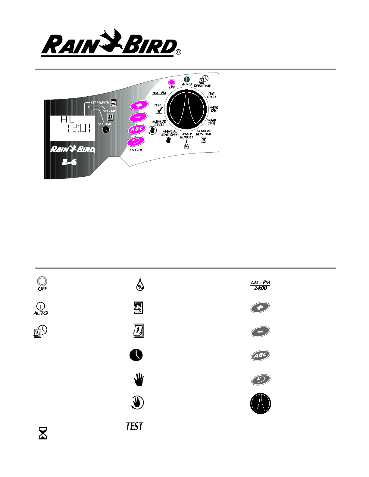
PROGRAMMING CONTROLS
The following is a key to the buttons and icons on the E-Class controller faceplate.
OFF
AUTOMATIC MODE
DATE/TIME
DAY CYCLE:
DAY CYCLEDAY CYCLE
WATER DAY:
WATER DAYWATER DAY
START TIME:
START TIMESTART TIME
WATER BUDGET
SET MONTH
SET DATE
SET TIME
MANUAL STATION(S) START
MANUAL PROGRAM (CYCLE)
START
TIME/DATE
OPTION
PLUS (add): +
MINUS (subtract): -
SELECT PROGRAM:
ABC
ENTER: ENTERENTER
CONTROLLER KNOB
(PROGRAMMING DIAL)
STATION RUN TIME
TEST PROGRAM
1
Page 2

WHAT MAKES UP A PROGRAM?
DAY CYCLE: The number of days before the cycle repeats, i.e., 7-day cycle: one week long: 3-day cycle: once every three days.
WATERING DAYS: set weekdays ON or OFF as watering days (7-day cycle). Set "Today's" number
within the cycle (1 through 6-day cycles).
START TIME: The time of day that the program begins. This is the time that the first station in the program begins watering. All other stations in the program then follow in sequence, AUTOMATICALLY.
STATION RUNTIME: The number of minutes that each station runs.
I. SET YEAR, DATE AND TIME
Turn the controller knob to DATE/TIME.
1.
The year 1996 will flash in the display. Press
2.
+ or - to set to the current year.
Press ENTERENTER to enter your selection.
3.
The digits for the current month will now
4.
flash (01). Press + or - to set to the current
month.
Press ENTERENTER to enter your selection.
5.
2 4 6 8 10
1
24:00
The digits for the current day will now flash
6.
(01). Press + or - to set to the current day.
Press ENTERENTER to enter your selection.
7.
The digits for the current hour will now flash
8.
(00). Press + or - to set to the current hour.
Press ENTER ENTER to enter your selection.
9.
The digits for the current minute will now
10.
flash (00). Press + or - to set to the current
minute.
Press ENTER ENTER to enter your selection.
11.
II. SET REPEATING DAY CYCLE
Set dial to day cycle.
1.
3 5 7 9 11
Select the day cycle and follow
3.
the applicable instructions.
Select the program.
2.
2
Page 3

AVAILABLE DAY CYCLES
Follow the next step for the cycle you choose.
1. 7-day (weekly) repeating cycle
Skip to step III
2. 1-day through 6-day cycle i.e., 3-day cycle =
water on day #1, skip #2 and #3, and then
start over. In the 1-day through 6-day cycles,
day #1 is always the only water day.
Skip to step III
3. EV = Waters on EVEN dates only
Skip to step IV
III. SET WATERING DAYS
7 DAY CYCLE
A
1 2 543 76
In this example, today is Friday, day #5.
1. The program appears with today’s number
and abbreviation. The seven weekdays are displayed as a row of numbers. For example Monday is #1, Tuesday is #2, etc.
4. Od = Waters on odd dates only
Skip to step IV
5. Od 31 =Waters on odd dates but not the last
odd date of any month
Skip to step IV
=
1
3. To turn a weekday ON as a water day press +
to put it back to it’s square.
=
1
2. The square around a day’s number means it
is a water day. To turn a weekday OFF as a water day, press - .
1-DAY THROUGH 6-DAY CYCLES
In the 1-day through 6-day cycles the only water
day is always Day #1 (shown in it’s square).
A
1 2 3
EXAMPLE OF A 3-DAY CYCLE.
4. Use the ENTER button to move along the row
of days and use + or - to set each weekday ON
or OFF. When done go to step IV.
A
1 2 3
Use + to set “Today” number. In this example,
the “Today” number was set to Day 3. Tomorrow, Day 1 will be the water day as the cycle
starts over. Now go to step IV.
3
Page 4
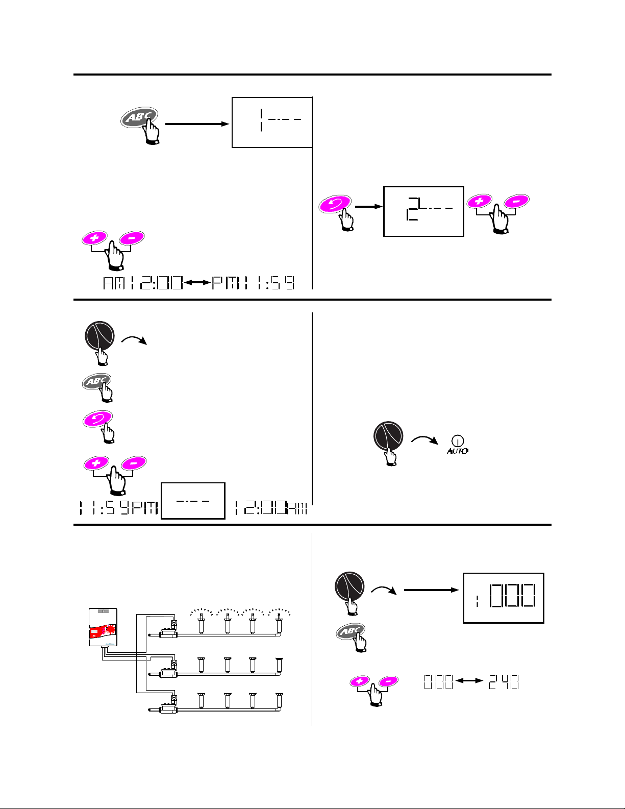
IV. SET WATERING START TIMES
Press SELECT PROGRAMSELECT PROGRAM.
1.
The program letter and “1” for Program Start
2.
Time One appear.
TO DELETE A START TIME
Turn dial to START TIMESTART TIME.
1.
Press SELECT PROGRAMSELECT PROGRAM.
2.
Set the time that you want the program to
A
2.
start.
Note: Remember, if you want all the stations on
the program to run only once each watering day,
enter only one start time for the program.
A
You can repeat entire programs several times
each water day. Press
2. There are 6 program start times available.
Move the start time to the blank screen just
4.
before midnight.
The E-Class controller automatically arranges
start times in the correct order. When a start
time is deleted, it’s empty gap is filled by the
next later start time.
ENTERENTER and repeat step
Repeatedly press ENTER
3.
until the start time you want
to delete appears in the
display.
V. SET STATION RUN TIMES
In this step you decide how long each STATION
WILL RUN.
EXAMPLE:
Turn the dial back to AUTO.
5.
If station 3 is in the same program (with #1 and
#2) it will run after STATION 2 is done, etc.
1.
2.
1 = Station 1
Press SELECT PROGRAMSELECT PROGRAM.
A
3.
Station OFF 4 hours
STATION 2 will begin watering when station 1
is done.
SET the station’s duration (running time) in minutes.
4
Page 5
V. SET STATION RUN TIMES - CONTINUED
4.
A
2 = Station 2
5.
Press ENTER to move to the next station. EACH TIME you give a STATION A RUNNING
TIME length you have added it to the Program.
When you are done, turn it back to AUTO.
When you have finished STEP V, you have completed the AUTOMATIC schedule for the Program.
If you want to set up another schedule, press the ABC button until the Program letter you want appears (A, B, or C) and then start over with STEP II.
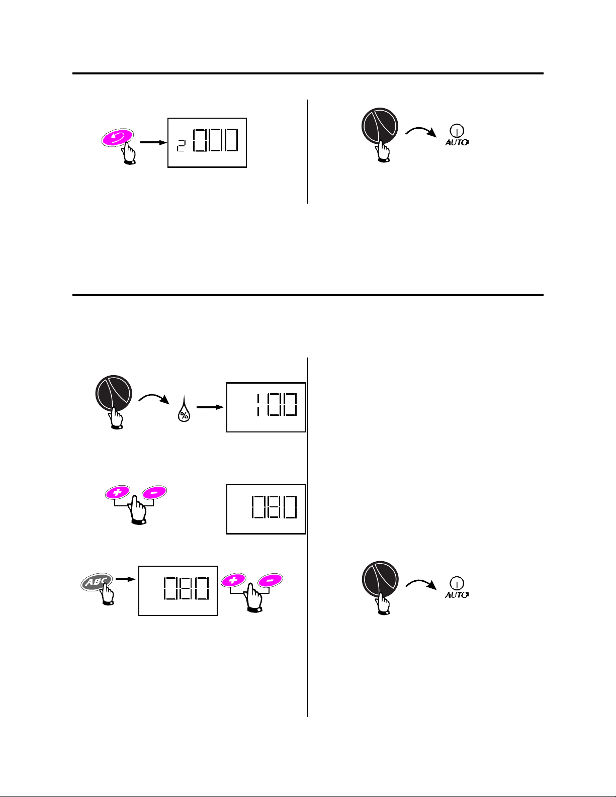
VI. ADJUST WATER BUDGET PERCENTAGE
WATER BUDGET allows you to increase or decrease watering time length for all stations on a Program with just one adjustment.
1.
A
4.
TO CANCEL A WATER BUDGET, set the % to 100.
000 = Individual Program OFF (0%)
2.
% A
3.
% A
. . .
TO SET ANOTHER PROGRAM’S WATER BUDGET
100 = 100% station time lengths. Normal running
length (NO WATER BUDGET)
70 = 70% of normal time lengths, perhaps for
cooler weather.
200 = Hot, dry weather - Double (200%) the
normal time lengths for all stations on the
Program.
%A, %B, %C
Indicates which Programs have WATER BUDGET in
effect.
5.
5
Page 6

VII. TO MANUALLY OPERATE STATION(S)
MANUAL STATION(S) allows you to manually run any station or stations you want for the number of
minutes you want. Normal station running times in the Automatic Programs are not affected.
1.
2.
3.
1 minute to 240 minutes
=
1 = STATION 1
2 = STATION 2
5.
Turn the dial back to AUTO. The controller will
run the station(s) you selected, and then return
to automatic mode and wait for the next start
time.
TO STOP MANUALLY STARTED STA-
6.
TION(S)
3 SECONDS
Turn the dial back to AUTO.
7.
Use ENTER ENTER to start the first station in your
Manual run and to move upward through the
stations.
4.
STOP AT ANY STATION YOU WANT, use + or
- to set a running time for it. Use ENTER ENTER to
put the station in line with the others and to
move upward again. Make sure to press EN-EN-
TERTER after setting the time on the last station
you have chosen.
6
Page 7

VIII. TO MANUALLY OPERATE PROGRAM(S)
1.
A
MANUAL CYCLE
Dial to Manual Cycle.
A B C
2.
Select the Program
3.
=
Start the Program using the ENTER button.
If you want to “stack” one of the other programs
to run following the first, repeat #2 and #3
above. The letter (A, B, or C) for the first
“stacked” Program will blink.
4.
TO STOP MANUALLY STARTED PRO-
5.
GRAMS(S)
6.
3 SECONDS
IX. TO RUN THE TEST PROGRAM
1.
TEST
2 = 2-minute test per station
2.
Set the minutes of running time from 1 - 10
3.
=
Press “Enter” to start the test cycle
4.
Turn the dial to AUTO. Each station will run for
the time you set. If a station has no running time
in any of the Automatic Programs, it will not operate during the TEST.
MANUAL ADVANCE
You can manually advance through the stations
of any program by setting the dial to AUTO and
repeatedly pressing the ENTER ENTER key.
7
Page 8

X. TO TURN CONTROLLER OFF
1.
No watering occurs, however, the controller
keeps the time, date, and your program in memory.
XI. TO SET DATE/TIME DISPLAY
Option
1.
2.
Return the controller to automatic operation.
To change between the English Time/Date system and the European method use this dial position and the ENTER button.
AM - PM
24:00
XII. MOISTURE SENSOR SETTING (IF INSTALLED)
PM 4:04
12/31/99
16:04
31/12/99
You can tell the controller to stop watering when an attached sensor reaches it’s “wet” condition. You
can also override a sensor if needed. When a sensor system interrupts watering, the controller continues it’s programs, the valves remain off.
If no sensor is attached to the controller, leave the wire loop in place that connects the two sensor
screws.
8
Page 9

XIII. ERASE ALL PROGRAMMING
With the dial at Auto, open and remove the lower cover. With a metal object, momentarily connect
two contacts at the back of the RESET Tunnel. When the display goes blank, remove the metal object. You can now reprogram the controller.
1.
3.
2.
4.
XIV. BACK-UP MEMORY (NO BATTERIES REQUIRED)
During a power outage
1. The display is blank
2. Time/Date/all Programs retained for 24-30
hrs.
3. Default Program if memory is lost and power returns:
Date: 01/01/96
Time: 12:00 AM
Start Time: 8:00 AM
All Stations: On Program A
Day Schedule: 7-day, water everyday
Station Timing: 10 minute each
The default program disappears as you start to reprogram.
XV. TROUBLESHOOTING
DIAGNOSTIC CIRCUIT BREAKER (No fuse required)
If the controller detects an electrical short circuit on one of the sprinkler system's station wires or valve
solenoids, the controller automatically shuts off the station with the fault. After 30 - 40 seconds, while the EClass unit is checking again to confirm the fault, the controller advances to the next station in the program.
Every 3 seconds, the controller will display the problem station's number with the letters "Err". The E-Class
controller will continue to run each operable station in the program. As each station is running, the controller
(at an alternate 3-second interval) will display the station's number and time-to-go.
When the controller finishes the program, it will continue to display the problem station's number and "Err".
At this point, you should isolate and repair the short circuit. Short circuits are most often found to be in the
valve solenoid (the plastic-encapsulated coil on the valve with the two wire leads) or in the wire connectors to
the valve leads. After you have found and repaired the short, turn the dial to AUTO and press
clear the "Err" message from the display. You can then operate the station manually to see if it works properly.
9
ENTERENTER to
Page 10

TROUBLESHOOTING GUIDE
SYMPTOM CAUSE CORRECTION
Display shows "Err"
Display shows "Err" for a few seconds and then the station in operation for a few seconds.
Display is blank.
Display shows numbers and letters, but is not counting or advancing.
Watering will not start.
1. The automatic circuit
breaker has found an electrical problem.
2. Same as Cause #1.
3. Power is off to the con-
troller
4. If the controller is still
receiving power, an electrical surge exceeding the
controller's built-in surge
protection may have damaged the controller's microprocessor.
5. Same as Cause #4.
6. Programming incom-
plete.
The "Err" in the display indicates a short circuit or an electrical overload on a particular
station. The station's number should also be
displayed; for example "2 Err" means the
problem is in Station Two's circuit.
Usually, the short circuit is in the solenoid on
the electric valve, but short circuits can also
occur in the wire connectors at the valve.
Occasionally, nicked or "skinned" field wires
can cause a short. A large pump start relay
can also produce a momentary overload that
may be detected by the controller.
Locate and repair the cause of the short circuit. See the "Diagnostic Circuit Breaker" on
page 9 for instructions on clearing the problem indicator from the display and testing
the station.
See correction for Cause #1.
Re-establish power to the controller. If the
current time is not shown or your program is
no longer in the memory, reprogram the
controller.
Open the lower access cover and erase all
programs as described on page 9.
If the display remains blank, the controller
may be permanently damaged.
In the U.S.A., Call 1-800-247-3782 for a service referral.
See correction for Cause #4.
Check to see if:
• program start time is correct
• stations are assigned to the program
• the date and time are correct in the display
• AM and PM settings are mixed up
• the dial is set to OFF instead of AUTO
Watering will not stop.
7. Sensor function may be
preventing irrigation.
8. Water supply may be
shut off.
9. Programs may have ac-
cidentally been set to overlap.
10. A valve is stuck in the
open position.
10
Set sensor switch to OFF position and manually start a station.
Check to see if water supply line has pressure.
Check to see if another program's start time
came due during the previous program's cycle. The overlapped program would immediately follow the earlier one. Change programming if necessary.
Turn dial to OFF and wait 10-20 seconds. If
the irrigation does not stop, shut off the
valve manually and repair the valve.
Page 11

XVI. INSTALLING THE CONTROLLER
NOTE: Even though directions for connecting the wiring to the controller are provided in this manual, local
electrical codes may vary in what is required for proper and safe installation. This controller must be installed
in compliance with local electrical codes
Rain Bird E-Class controllers are available in either indoor or outdoor models. Indoor models have a separate
transformer. Outdoor models have a built-in transformer and a separate plastic junction box.
CHOOSE LOCATION
Choose a mounting location near an electrical power source. For the indoor controller, the mounting
location must be within 5' (1.5 m) of the electrical wall outlet.
For the outdoor controller, the wires from the source of electrical power to the controller need to be
protected in a conduit that meets local electrical code requirements for high voltage (either 120 or
230 volt) circuits. Even though the outdoor model is housed in a weather-resistant cabinet, choose a
location that is somewhat sheltered if possible.
Note: The sliding door (cover) on the outdoor models must be left in the down (closed) position to
provide weather and water spray protection to the controller.
MOUNT CONTROLLER
Note 1: Allow 7-1/2" inches of clearance above the
top of the controller (or 8-1/2" above the upper edge
of the wall mounting bracket) so you will have room
to slide the controller down over the wall mounting
bracket (on models with a sliding door, this overhead
clearance also allows the door to be removed or reinstalled).
Note 2: For indoor units that do not have a sliding
door, the overhead clearance can be reduced to 2"
above the top of the controller (or 3" above the top of
the wall mount bracket). This lower clearance may be
needed, for example, if the only mounting location
was for the controller under a shelf on the garage
wall. See note 3 on page 12 on how to mount the
controller using this lower clearance.
A B C
1. Holding mounting bracket to the wall or other
mounting surface, at about eye level, mark, with a
pencil, the location for screws or fasteners at the top
of the narrow slot(s). For a flat surface, use keyhole
slots "A" and "C" for the fasteners. If you are mounting the controller on a narrow post or exposed wall
stud, use keyhole slot "B". The bracket's upper slots
are sized for the head of a Number 8 screw, however,
you will need the type of fasteners appropriate for
your wall's surface. Remove the bracket and drive the
fastener(s) into the wall where you made the marks
in the upper slot(s) only. (See illustration.) DO NOT
drive a fastener through hole "D" at this time.
Leave 1/4" of the fastener's shaft showing between
the wall and its head. Hang the wall bracket on the
fasteners by the upper slot(s). Tighten or loosen the
fasteners for a snug fit that will still allow the bracket
to slide up and off the fasteners should it ever be
necessary. With a nail or punch, tap a pilot hole in
the wall through the center of hole "D".
D
11
Page 12

2. Pull upward on the slid-
ing door (for controllers
with doors) to the latched
position that exposes the
face panel controls and
then with a firmer tug pull
the door upward and off
the controller. Remove the
lower access cover by
placing your fingers under
the door at the bottom of
the controller and your
thumb on top of the access
door on its latch hook.
Then, press gently down
on the latch hook and
swing the door outward
and downward away from
the controller. Turn the
controller upside down on
the edge of a flat surface
(see illustration).
3. Place a flat blade screwdriver in the groove of the
knockout labeled "A" in the illustration. With the
palm of your hand, strike the end of the screwdriver
handle to punch in one side of the knockout. Repeat
the process on the other edge of the knockout and
remove it. One knockout hole is sized for 3/4" conduit. If the size and number of valve wires require
more than 3/4" conduit, punch out the second
knockout for 1 " conduit instead.
wall bracket up into its
tracks on the back of the
controller and, together,
mount the bracket and
controller back on the wall.
Make sure that hole "D" in
the bracket and the hole in
the back of the lower compartment of the controller
are aligned with each other
and with the pilot hole in
the wall's surface.
CONNECT MAIN POWER WIRES
WARNING: Make sure the power source is off before
connecting any power wires.
OUTDOOR CONTROLLER
4. Slide the controller down over the mounting
bracket until lower mounting hole "D" aligns with the
hole in the back of the terminal strip compartment.
You may want to wait until after you have cut your
wire conduits to length before driving the last mounting screw through the aligned holes to secure the
controller to the wall or stud.
Note 3: For installations with low overhead clearance
(and with no controller sliding door), slide the wall
bracket up and off the wall. Slide the
The illustrated "side view" shows how the controller,
"J" box, conduit and fitting are used for outdoor installations.
The slide-in clip holds the "J" box to the controller,
however, the "J" box must be screwed to the wall.
Cut both the power supply conduit to the right length
and your valve wire conduit.
12
Page 13

U.S. VERSION, 117-120 VAC, 60HZ)
1. Unscrew and remove the cover of the junction box
and remove the clip that is supplied with it. Carefully
punch in and remove knockout "E" in the end of the
junction box and punch out the two small holes "F" &
"G" (see illustration).
2. Cut the power input wires from the controller and
the supply wires from the power source to a convenient length, approximately 3" (75 mm) for making
wire connections. Strip approximately 1/2" (12.5
mm) of the installation from the end of each wire
(see illustration).
3. With code-approved wire connectors, connect the
green wire (sometimes this a completely bare, copper wire) from the power source to the green/yellow
wire from the controller. In a similar manner, connect each of the two remaining power source wires
to one of the controller’s input wires (see illustration).
4. Carefully coil or bend the wires to fit them and
their connectors into the junction box. Reattach the
cover to the junction box.
OUTDOOR CONTROLLER (INTERNATIONAL
VERSION, 230 VAC)
The main power connections for the 230 VA. versions of the E-Class controller are very similar to
the U.S. version described previously. The only exception is that there are only two main power input
wires coming from the controller. Connect each of
these two input wires to one of the power wires
coming from the 230 VAC power source (see illustration). Use wire connectors that meet local electrical codes.
INDOOR CONTROLLER (117-120 VOLT 60 HZ
VERSION)
1. Before connecting the external transformer to the
controller, make sure the transformer is NOT
plugged in.
2. Feed the wires from the transformer through the
left-hand hole in the bottom of the controller. Pull
about 10" (25.5 cm) of the wire out through the front
of the compartment. To provide strain relief, loop
the wire into a simple overhand knot, leaving the
ends of the wire between 3" and 4" (7.7 cm and 10.2
cm) beyond the knot. Pull the excess wire back out
of the bottom of the controller until the knot reaches
the hole (see illustration).
3. Connect the green wire from the transformer to
the far left screw (GND) on the terminal strip. Connect each of the two remaining wires to one of the
screws labeled "24 VAC".
4. Plug the transformer into any standard, 3-prong
117 VAC grounded wall outlet.
13
Page 14

INDOOR CONTROLLER (230 VOLT 50HZ INTERNATIONAL VERSION)
Because of the wide variety of plug patterns used
for electrical wall outlets around the world, the indoor controller provides a separate transformer with
a two-wire, 230 VAC input to which you can attach
the proper plug. After attaching the plug to the input
wires, do not plug the transformer in.
The transformer has plastic loops that allow you to
screw it to the wall surface at a convenient location.
The two 24 VAC output wires are to be attached to
the "24 VAC" screws before plugging in the power
cord. (See illustration.)
CONNECT FIELD WIRES TO REMOTE CONTROL VALVES
NOTE: The E-Class, residential controller is designed to work best with #18 gauge, multi-conductor cable that
is approved for low-voltage, direct burial applications. These cables usually have a white insulated wire for
Valve Common and then a different color wire for each station valve, all contained within an outer jacket.
The wires coming back to the controller from the electric valves in the field can be routed into the controller
through the larger hole(s) in the bottom of its cabinet. For a clean, professional look to the installation, the hole
size is for a 3/4" PVC conduit to house the wires (or for 1" PVC). The upper ends of the conduit(s) should end
about 1/4 inch inside the bottom of the controller.
If using a pump: connect unused stations to the closest used ones.
SENSOR
SYSTEM
MASTER
VALVE
STATION VALVES
14
Page 15

CONNECT FIELD WIRES TO REMOTE CONTROL VALVES - continued
The illustration shows the various wire runs and connections between the controller and other devices. Each
valve to be controlled by the E-Series controller should have its own, separate power wire. Connect one end of
the power wire to a numbered station terminal on the controller's terminal strip. Connect the other end of the
power wire to one of the wire leads on the valve solenoid. The wire connectors at the valves must be waterproof.
Connect the white valve common wire to the "C" terminal on the terminal strip. The valve common wire should
follow the route out along the valve locations and should connect to the remaining wire lead on each valve.
If your system includes a master valve on its main line supply or a 24-volt-activated pump start relay (for activating a pump during irrigation) connect a wire from the device to the "MV" terminal on the controller. (The
controller does not provide the main power for a pump.) Connect the other wire lead on the device to the valve
common wire. If you are connecting a pump start relay, follow the wiring directions that came with the relay.
4. Warning for Systems Using Pump Start Relays: If you are using the pump start/MV circuit to turn on the
pump for your system, you must connect any unused stations to the last station that does not have a valve
connected to it. For example, if you have a 6-station controller and only stations 1-4 are connected to valves in
the system, connect terminals 5 and 6 to station #4 with a short wire on the terminal strip. Then, if a prolonged
power outage outlasts the controller's memory protection, and the controller activates its default program,
when the pump and stations #5 or #6 are running, station #4's valve allows water-flow to prevent the pump
from overheating. (See previous illustration on page 14.)
5. If you are not going to connect a sensor system to the E-Series controller, you have now completed the
mounting and wiring procedures for the unit. Replace the lower access cover on the controller, and you are
ready to begin programming.
CONNECT SENSOR
The E-Class controller is compatible with several types of rain sensors and underground moisture sensor systems.
1. To connect a sensor system to the E-Class controller, first loosen the screws at the two SENSOR positions
on the terminal strip, and remove the jumper wire connecting them.
2. Attach one wire to each of the SENSOR positions on the controller's terminal strip. Route the pair of wires
out of the controller to the sensor system. Connect the two wires to the two wire leads or terminals on the sensor.
NOTE: Most sensor systems have two wire leads or two terminals designed to connect to the valve common
wire. However, you must connect these two leads or terminals to the SENSOR terminals on the E-Class controller.
3. After installing the sensor system and hooking up the sensor wires from the controller, follow the sensor
system's directions for placing and connecting moisture probes or setting the rain shutoff level, and making
final adjustments.
4. After adjusting your sensor system, set the controller's SENSOR switch to the ON position. See "Moisture
Sensor Setting" on page 8 of this manual.
15
Page 16

This controller generates radio frequency energy and may cause interference to radio and television reception.
It has been type tested and found to comply with the limits for a Class B computing device in accordance with
the specifications in Subpart J of Part 15 of FCC Rules, which are designed to provide reasonable protection
against such interference in a residential installation. However, there is no guarantee that interference will not
occur in a particular installation.
If this equipment does cause interference to radio or television reception, which can be determined by turning
the equipment off and on, the user is encouraged to try to correct the interference by one or more of the following measures:
• Reorient the receiving antenna.
• Move the controller away from the receiver.
• Plug the controller into a different outlet so that the controller and receiver are on different branch circuits.
If necessary, the user should consult the dealer or experienced radio/ television technician for additional suggestions. The user may find the following booklet prepared by the Federal Communications Commission helpful:
"How to Identify and Resolve Radio-TV Interference Problems."
This booklet is available from the U.S. Government Printing Office, Washington, D.C. 20402,
Stock No. 004000003454.
PREFERRED BY PROFESSIONALS WORLDWIDE
Rain Bird Sales, Inc.
Customer Support Center
6991 E. Southpoint Rd., Bldg. #1
Tucson, AZ 85706
1-800-RAIN BIRD
(520) 434-6290 FAX
© 1998 Rain Bird Sprinkler Mfg. Corp.
® Registered trademark of Rain Bird Sprinkler Mfg. Corp.
PN 633659B
16
 Loading...