

Page 1

MiniRAE 2000
Portable VOC Monitor
PGM-7600
OPERATION AND MAINTENANCE
MANUAL
(Document No.: 011-4001)
Rev. C2
RAE SYSTEMS INC.
1339 Moffett Part drive
Sunnyvale, CA 94089
April 2003
i
Page 2

ATTENTION!
For European Applications
A. 0575 II 1G/2G
DEMKO 03 ATEX 0204759X
Eex ia IIC T4
B. Recharge batteries only in non-hazardous locations.
C. Do not connect external cable to serial interface jack in
hazardous locations.
D. Use RAE Systems Adapter P/N 500-0072 for connection
to communication port and charging jack only in a non-
hazardous area.
ii
Page 3

Table of Contents
1. GENERAL INFORMATION.............................. 1-1
1.1 General Specifications .............................................. 1-2
2. OPERATION OF MINIRAE 2000 ..................... 2-1
2.1 Physical Description ................................................. 2-2
2.2 Keys and Display ......................................................2-3
2.3 Power On/Off............................................................ 2-5
2.4 Operation................................................................... 2-7
2.4.1 Survey Mode ....................................................... 2-8
2.4.2 Hygiene Mode ................................................... 2-13
2.5 Alarm Signals.......................................................... 2-15
2.6 Preset Alarm Limits and Calibration ...................... 2-17
2.7 Integrated Sampling Pump...................................... 2-18
2.8 Back Light............................................................... 2-19
2.9 Datalogging............................................................. 2-20
3. OPERATION OF ACCESSORIES .................... 3-1
3.1 Standard Kit and Accessories.................................... 3-2
3.2 Optional Accessories................................................. 3-5
4. PROGRAMMING OF MINIRAE 2000............. 4-1
4.1 Programming Mode .................................................. 4-2
4.2 Keys for Programming Mode ................................... 4-3
4.3 Entering into Programming Mode ............................4-4
4.4 Calibrate and Select Gas ........................................... 4-5
4.4.1 Fresh Air Calibration...........................................4-8
4.4.2 Span Calibration .................................................. 4-9
4.4.3 Select Cal Memory ............................................ 4-11
4.4.4 Change Span Value ........................................... 4-12
4.4.5 Modify Cal Memory.......................................... 4-13
4.4.6 Change Correction Factor.................................. 4-15
4.5 Change Alarm Limits.............................................. 4-16
4.5.1 Change Low Alarm Limit .................................4-18
4.5.2 Change STEL Limit .......................................... 4-19
4.5.3 Change TWA Limit...........................................4-20
4.6 View or Change Datalog......................................... 4-21
i
Page 4

4.6.1 Reset Peak/Minimum ........................................ 4-22
4.6.2 View Data (Datalog).......................................... 4-23
4.6.3 Clear Data..........................................................4-25
4.6.4 Change Data Period...........................................4-26
4.6.5 Change Average Type ....................................... 4-27
4.7 Change Monitor Setup ............................................ 4-28
4.7.1 Change Operation Mode.................................... 4-29
4.7.2 Change Site ID .................................................. 4-30
4.7.3 Change User ID ................................................. 4-31
4.7.4 Change Alarm Mode?........................................ 4-32
4.7.5 Change User Mode ............................................ 4-33
4.7.6 Change Date ...................................................... 4-34
4.7.7 Change Time ..................................................... 4-35
4.7.8 Change Lamp.................................................... 4-36
4.7.9 Change Unit....................................................... 4-37
4.7.10 Change Dilution Ratio....................................... 4-38
4.7.11 Change Output? ................................................. 4-39
4.7.12 Change DAC Range? ........................................4-40
4.7.13 Set Temperature Unit?....................................... 4-41
4.8 Exit Programming Mode......................................... 4-42
5. COMPUTER INTERFACE ................................ 5-1
5.1 Installing ProRAE-Suite Software ............................ 5-2
5.2 Connect MiniRAE 2000 to PC.................................. 5-4
5.3 Start ProRAE-Suite Software.................................... 5-5
5.4 Setup Communication Port ....................................... 5-7
5.5 Processing the Configuration Data............................ 5-8
5.5.1 Editing the Configuration Data ...........................5-9
5.5.2 Send Configuration............................................ 5-16
5.5.3 Saving Configuration Data................................ 5-17
5.5.4 Configuring All Settings.................................... 5-18
5.6 Processing the Logged Data.................................... 5-19
5.6.1 Receiving Data .................................................. 5-20
5.6.2 View Logged Data in Text Mode...................... 5-21
5.6.3 View STEL/TWA/AVG Value .........................5-23
5.6.4 View Summary Information.............................. 5-24
ii
Page 5

5.6.5 View Logged Data in Graph Mode ................... 5-25
5.6.6 Exporting Data to a Text File ............................ 5-29
5.6.7 Exporting Graphics to a File.............................. 5-30
5.6.8 Printing Logged Data ........................................ 5-31
5.7 Installing Datalog Capability .................................. 5-32
5.8 Upgrade the Firmware ............................................ 5-34
6. THEORY OF OPERATION............................... 6-1
7. MAINTENANCE.................................................. 7-1
7.1 Battery Charging and Replacement .........................7-1
7.2 PID Sensor & Lamp Cleaning /Replacement............ 7-4
7.3 Sampling Pump ......................................................... 7-7
7.4 Turning on the UV Lamp.......................................... 7-9
8. TROUBLESHOOTING....................................... 8-1
8.1 Special Diagnostic Mode .......................................... 8-2
8.2 Troubleshooting Table ............................................ 8-10
APPENDIX A. QUICK REFERENCE GUIDE..... A-12
APPENDIX B. REPLACEMENT PARTS LIST ....B-12
APPENDIX C. TECHNICAL NOTES.................... C-12
APPENDIX D. APPLICATION NOTES................ D-12
APPENDIX E. LITERATURE REQUEST.............E-12
APPENDIX F. REQUEST FOR RETURN
AUTHORIZATION FORM .................................F-12
Main Contact Numbers.................... Outside Back Cover
iii
Page 6

! WARNING !
- Do NOT proceed before reading -
This manual must be carefully read by all individuals
who have or will have the responsibility for using,
maintaining, or servicing this product.
The product will perform as designed only if it is used,
maintained, and serviced in accordance with the manufacturer's
instructions.
CAUTION!!
To reduce the risk of electric shock, turn off power
before removing the monitor cover. Disconnect the
battery before removing sensor module for service.
Never operate the monitor while the cover is removed.
Remove monitor cover and sensor module only in an
area known to be non-hazardous.
The model PGM-7600 equipment is classified as to
intrinsic safety for use in class I, division 1, groups A,
B, C, D, or non-hazardous locations only.
iv
Page 7

Special Notes
-1-
When the MiniRAE 2000 Monitor is taken out from the
transport case and turned on for the first time, there
may be some residual organic or inorganic vapor
trapped inside the detector chamber. The initial PID
sensor reading may indicate a few ppm. Enter an area
known to be free of any organic vapor and turn on the
monitor. After running for several minutes, the
residual vapor in the detector chamber will be cleared
and the reading should return to zero.
-2-
The battery of the MiniRAE 2000 monitor will
discharge slowly even if it is turned off. If the monitor
has not been charged for 5-7 days, the battery voltage
will be low. Therefore, it is a good practice to always
charge the monitor before using it. It is also
recommended to fully charge the monitor FOR AT
LEAST 10 HOURS before first use. See Section 7 for
more information on battery charging and
replacement.
STATIC HAZARD:
Clean only with damp cloth.
DANGER RISQUE D'ORIGINE
ELECTROSTATIQUE:
Nettoyer uniquement avec un chiffon humide.
v
Page 8

CAUTION:
For safety reasons this equipment must be operated
and serviced by qualified personnel only. Read and
understand instruction manual completely before
operating or servicing.
ATTENTION:
Pour des raisons de sécurité, cet équipment doit être
utilisé, entretenu et réparé uniquement par un
personnel qualifié. Étudier le manuel d’instructions en
entier avant d’utiliser, d’entretenir ou de réparer
l’équipement.
WARNINGS:
Use only RAE Systems battery packs, part nos. 012-
3050, 012-3051 or 012-3052. This instrument has not
been tested in an explosive gas/air atmosphere having
an oxygen concentration greater than 21%.
Substitution of components may impair intrinsic safety.
Recharge batteries only in non-hazardous locations.
AVERTISSEMENT:
Utiliser seulement l'ensemble de batterie RAE Systems,
la reference 012-3050, 012-3051 au 012-3052. Cet
instrument n’a pas été essayé dans une atmosphère de
gaz/air explosive ayant une concentration d’oxygène
plus élevée que 21%. La substitution de composants
peut compromettre la sécurité intrinsique. Ne charger
les batteries que dans emplacements désignés non-
dangereuse.
vi
Page 9

CAUTION WARNINGS:
The calibration of all newly purchased RAE Systems
instruments should be tested by exposing the sensor(s)
to known concentration calibration gas before the
instrument is put into service.
For maximum safety, the accuracy of the MiniRAE
2000 should be checked by exposing it to a known
concentration calibration gas before each day’s use.
AVERTISSEMENT:
La calibration de toute instruments de RAE Systems
doivent être testé en exposant l’instrument a une
concentration de gaz connue par une procédure
diétalonnage avant de mettre en service l’instrument
pour la première fois.
Pour une securite maximale, la sensibilité du
MiniRAE 2000 doit être verifier en exposant
l’instrument a une concentration de gaz connue par
une procédure diétalonnage avant chaque utilisation
journalière.
vii
Page 10

GENERAL INFORMATION
1. GENERAL INFORMATION
MiniRAE 2000 Portable VOC Monitor (Model PGM
7600) is a compact monitor designed as a broadband VOC
gas monitor and datalogger for work in hazardous
environments. It monitors Volatile Organic Compounds
(VOC) using a Photo-Ionization Detector (PID) with a 9.8
eV, 10.6 eV, or 11.7 eV gas discharge lamp. Features are:
• Lightweight and Compact
-Compact, light weight (19 oz.) and rugged design
-Built-in sample draw pump
• Dependable and Accurate
- Up to 10 hours of continuous monitoring with
rechargeable battery pack
- Designed to continuously monitor VOC vapor at ppm
levels
• User Friendly
-Preset alarm thresholds for STEL, TWA, low and high
level peak values. Audio buzzer and flashing LED
display are activated when the limits are exceeded.
• Datalogging Capabilities
-15,000 point datalogging storage capacity for data
download to PC
MiniRAE 2000 consists of a PID with associated
microcomputer and electronic circuit. The unit is housed
in a rugged ABS + PC case with a backlit 1 line by 8
character dot matrix LCD and 3 keys to provide easy user
interface.
1-1
Page 11

GENERAL INFORMATION
1.1 General Specifications
Table 1.1
Portable VOC Monitor Specification
Size: 8.2"L x 3.0"W x 2.0"H
Weight: 19.5 oz with battery pack
Detector: Photo-ionization sensor with 9.8, 10.6,
or 11.7 eV UV lamp
Battery: A 4.8V /1250 mAH Rechargeable
Nickel Metal Hydride battery pack
(snap in, field replaceable)
Battery Charging: 10 hours charge through built-in
charger
Operating Hours: Up to10 hours continuous operation
Display: 1 line by 8 characters 5x7 dot matrix
LCD (0.4” character height) with LED
back light automatically in dim light
Range, Resolution & Response time (t90):
Isobutylene (calibration gas)
0-99 ppm 0.1 ppm 2 sec
100-1,999 ppm 1.0 ppm 2 sec
2000-10,000 ppm 1.0 ppm 2 sec
Measurement Accuracy (Isobutylene):
0 – 2000 ppm: ± 2 ppm or 10% of
reading.
> 2000 ppm: ± 20% of reading
PID Detector: Easy access to lamp and sensor for
cleaning and replacement
Correction Factors: Built-in 102 VOC gases
1-2
Page 12

GENERAL INFORMATION
Calibration: Two-point field calibration of zero
and standard reference gas
Calibration Memory:
Store up to 8 separate calibration,
alarm limits and span value
Inlet Probe: Flexible 5” tubing
Keypad: 1 operation key and 2 programming
keys
Direct Readout: Instantaneous, average, STEL and
peak value, battery voltage and
elapsed time
Intrinsic Safety: UL & cUL Class 1, Division I, Group
A,B,C,D, Temperature Code T3C (US
& Canada); 0575 II 1G
DEMKO 02 ATEX 0204759
Eex ia IIC T4 (Europe)
EM Interference: No effect when exposed to 0.43
W/cm2 RF interference (5 watt
transmitter at 12 inches)
Alarm Setting: Separate alarm limit settings for Low,
High, STEL and TWA alarm
Operating Mode: Survey or Hygiene mode
Alarm: 90 dB buzzer and flashing red LEDs
to indicate exceeded preset limits, low
battery voltage, or sensor failure.
External Alarm: Optional plug-in pen-size vibration
alarm or remote alarm
Alarm Mode: Latching or automatic reset
1-3
Page 13

GENERAL INFORMATION
Real-time Clock: Automatic date and time stamps on
data logged information
Datalogging: 15,000 points with time stamp, serial
number, user ID, site ID, etc.
Communication: Upload data to PC and download
instrument setup from PC through RS-
232 port
Sampling Pump: Internally integrated. Flow rate: 450-
550 cc/min.
Temperature: 0º to 45ºC (32º to 113ºF)
Humidity: 0 % to 95 % relative humidity
(non-condensing)
Housing: ABS + PC, conductive coating, splash
and dust proof, will withstand 1 meter
drop test with rubber boot
Attachment: Wrist strap, rubber boot and belt clip
1-4
Page 14
OPERATION
2. OPERATION OF MINIRAE 2000
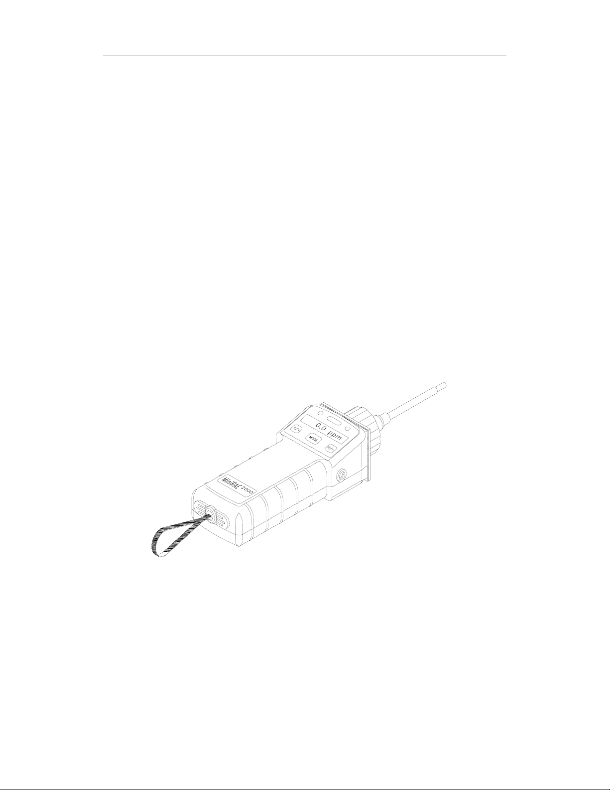
The MiniRAE 2000 Portable VOC Monitor is a compact
Monitor designed as a broadband VOC gas monitor and
datalogger for work in hazardous environments. It gives
real time measurements and activates alarm signals
whenever the exposure exceeds preset limits. Prior to
factory shipment the MiniRAE 2000 is preset with default
alarm limits and the sensor is pre-calibrated with standard
calibration gas. However, the user should test the
instrument and verify the calibration before the first use.
After the monitor is fully charged and calibrated, it is ready
for immediate operation.
Figure 2-1 MiniRAE 2000
2-1
Page 15

OPERATION
2.1 Physical Description
The main components of the MiniRAE 2000 Portable
VOC monitor include:
• Three keys for user to interact with the monitor: 1
operation key and 2 programming keys for normal
operation or programming of the monitor
• LCD display with back light for direct readout and
calculated measurements
• Buzzer and red LED’s for alarm signaling whenever
the exposures exceed preset limits
• Wrist strap
• Charge contact for plugging directly to the charging
station
• Gas entry and exit ports
• Serial communication port for PC interface
• External alarm and analog output port
• Protective rubber cover
2-2
Page 16
OPERATION
pp
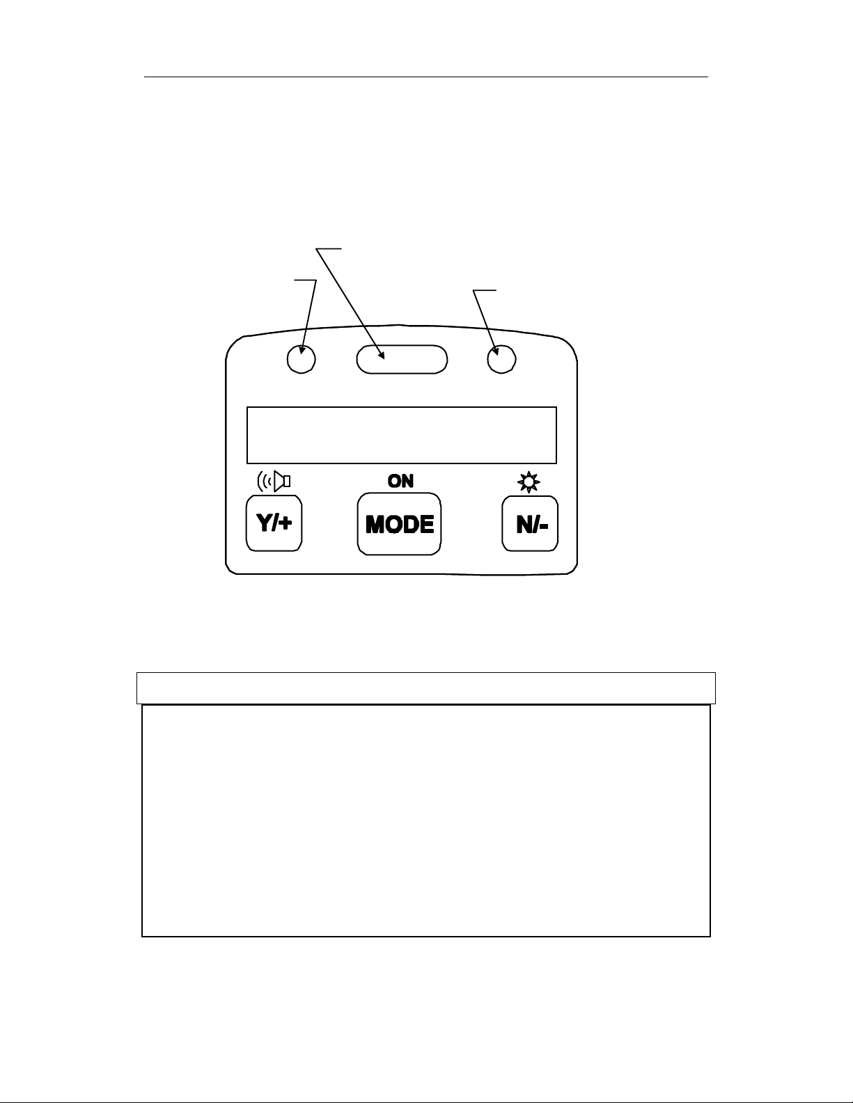
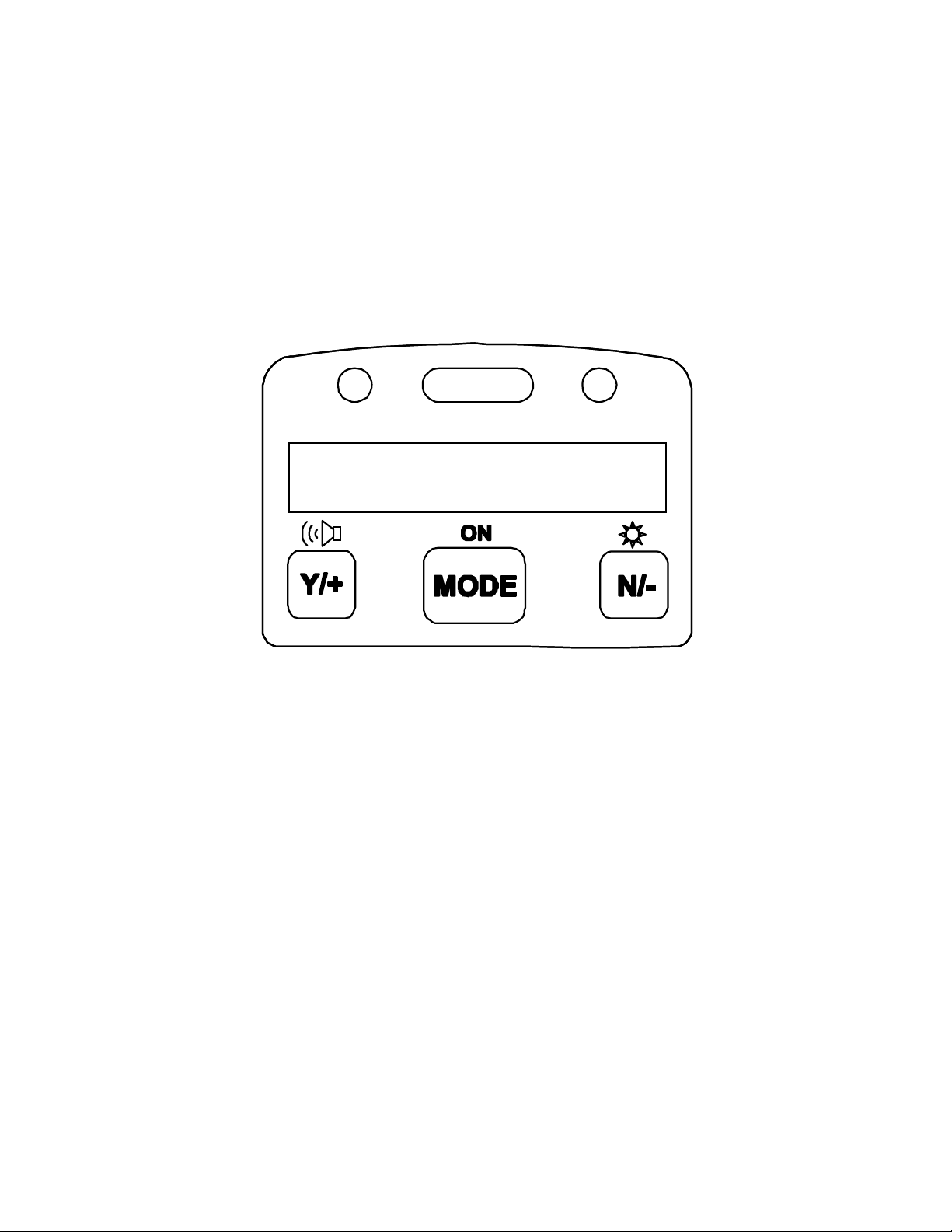
2.2 Keys and Display
Figure 2.2 shows the LCD display and the keypad on the
front panel of the monitor. The function of the 3 keys
during normal operation are summarized below:
Light sensor
Alarm LED’s
Charge LED
0.0
Figure 2-2 LCD Display and Keypad
Key Function in Normal Operation
[MODE] -Turn on/off the power* and step through
menu items
[N/-] -Toggle on/off the back light, negative
acknowledge/decrement value
m
[Y/+] -Start measurement, positive
acknowledge/increment value
2-3
Page 17

OPERATION
* Pressing and holding [MODE] key for 5 seconds turns
off the power to the monitor. Monitor will beep once per
second and display countdown timer during power-down
sequence. Press [MODE] key momentarily to step
through menu items. To save time, press any key during
message scrolling to skip to the end of the message.
2-4
Page 18

OPERATION
2.3 Power On/Off
To turn on the MiniRAE 2000 portable VOC monitor,
press [MODE] key for one second and release. The audio
buzzer will beep once and the air pump will turn on. The
display will show “ON!..” and then “Ver n.nn” to indicate
the unit’s current firmware version number. Next displayed
are the serial number, the model number, Operating mode,
current date and time, unit internal temperature, gas
selected, high low, STEL, TWA/AVG alarm limits, battery
voltage, and shut off voltage. Also displayed are internal
mode settings such as User mode, Alarm mode, datalog
time remaining and log periods in the respective order.
To turn off the MiniRAE 2000 portable VOC monitor,
press and hold the [MODE] key for 5 seconds. The
monitor will beep once per second during the power-down
sequence with a count down timer showing the number of
remaining seconds. The message “Off!..” flashes on the
LCD display and the display will go blank indicating that
the monitor is turned off.
Data protection during power off
When the monitor is turned off, all the current real time
data including last measured value are erased. However,
the datalog data is preserved in non-volatile memory. Even
if the battery is disconnected, the datalog data will not be
lost. While the power is off, the real time clock will
continue to operate until the battery is completely drained
(usually in 4-5 days without any charging). If the battery
2-5
Page 19

OPERATION
is completely drained or is disconnected from the monitor
for more than 30 minutes, the real time clock will be lost.
In this case, the user needs to enter the real time clock
information again, as described in Section 4, or send the
PC clock during configuration through the PC
communication.
2-6
Page 20

OPERATION
2.4 Operation
The MiniRAE 2000 VOC monitor has two operation
modes: Survey and Hygiene mode. The Survey mode
allows the user to manually start and stop the
monitoring/measuring operation and display certain
exposure values. In the Hygiene mode, the monitor runs
continuously after the monitor is turned on. Refer to
Section 4.7.1 for switching between the two modes.
2-7
Page 21
OPERATION
2.4.1 Survey Mode
After the monitor is turned on, it runs through the start up
menu. Then a message “Ready..” is displayed (see figure
below). At this point, the user has two options; 1) step
through the operation menu, or 2) take a measurement.
Ready …
Press the [MODE] key to cycle through the idle operation
menu. The PID sensor and pump are turned off during this
idle operation.
Main operation menu displays include:
• “Ready…”
• Avg reading
• Peak reading
• Run time
• Current battery voltage and shutdown voltage
• Date, time and temperature
• Log on/off?
• PC communication?
• Survey, Site ID and Gas Name
2-8
Page 22
OPERATION
g
)
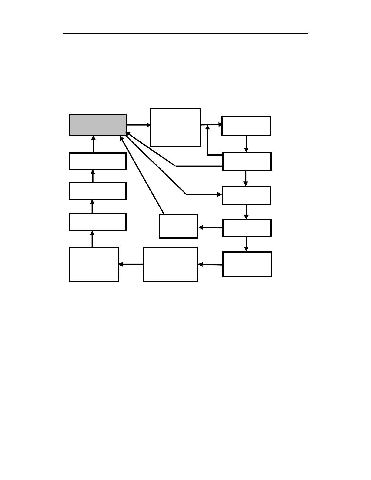
The displays are arranged in a “round robin” order:
To choose a specific display, press the [MODE] key one or
more times until the desired display appears.
SURVEY MODE MAIN MENU
Ready…
Survey
PC Comm?
Log On/Off?
11/18/98
10:30
T=70F
MODE
MODE
MODE
Y
MODE
Site ID = xx
Gas = xxxx
(Resets Peak
& Avera
Y
Reset
Peak?
Bat = 4.8V
Shut Down
at=4.2V
e
MODE
N
Y
Y
MODE
0.0 ppm
MODE
Stop?
MODE
Avg 0.0
MODE
Peak 0.0
MODE
Run time
00:00
Notes: The Site ID, Gas, Stop? ppm Reading and Stop?
screens are only shown after a measurement has been
started, not during idle operation. The Log On/Off? screen
is not shown when datalogging is disabled. The Ready
screen is skipped if the menu is cycled through while a
measurement is running.
More Details on the Main Operation Menu:
• READY: The monitor is ready to take a measurement.
Press the [MODE] key to advance to the next menu. Or
Press [Y/+] key to start a measurement (read “Taking a
Measurement” on page 2-11 for details).
2-9
Page 23

OPERATION
• AVERAGE READING: The TWA or running
average since the start of the measurement (see Section
4.6.5 to change). The average is recalculated every
minute.
• PEAK READING: The highest instantaneous reading
since the start of the measurement. If [Y/+] is pressed
while the peak reading is displayed, the unit will ask
“Reset Peak?” If [Y/+] is pressed again, the peak value
will be cleared and the display will return to the
“Ready” message or instantaneous reading. The peak
reading is automatically reset when a new measurement
is started by pressing [Y/+] from the “Ready…” screen.
• RUN TIME: The current measurement has been last.
• CURRENT BATTERY VOLTAGE and SHUT
DOWN VOLTAGE: The present battery voltage is
displayed.
Note: A fully charged battery pack should show 4.8 volts
or higher. When the battery voltage falls below 4.4 volts, a
flashing “Bat” will appear as a warning message. There are
about 20-30 minutes of run time left before the monitor
turns off automatically, when the battery voltage falls
below 4.2 volts.
• DATE, TIME, TEMPERATURE: This menu
displays the current date (month/day/year), time (24hour format), and internal unit temperature in degrees
Fahrenheit.
• LOG ON/OFF? Allows the user to start datalogging of
the current measurement. A superscript “L” flashes in
the ppm measurement display when datalogging is on.
2-10
Page 24

OPERATION
Note: Before datalogging can be turned on, this function
must be enabled as described in Section 4.6.4.
• PC COMMUNICATION: Allows the user to upload
data from the MiniRAE 2000 to a Personal Computer
(PC) or send/receive configuration information between
a PC and the MiniRAE 2000. Connect the monitor to a
serial port of a PC, and start the MiniRAE 2000
application software. Press the [Y/+] key and the LCD
displays “pause monitor, ok?” Press the [Y/+] key one
more time, the display shows “Comm...” The monitor
is now ready to receive commands from the PC.
• CURRENT OPERATING MODE: The monitor
displays the current operating mode e.g.; “Survey”, the
site ID, gas name and then returns to “Ready..”
To choose a specific display, press the [MODE] key one or
more times until the desired display appears.
Taking a measurement:
There are two ways to start a measurement. 1) Operating in
Hygiene mode. 2) Manually start and stop measurement in
Survey mode. To start a measurement in Hygiene mode,
please refer to Section 4.7.1 on “Change Op mode”. To
start a measurement in Survey mode, the MiniRAE 2000
monitor must first be in the “Ready…” mode. This is the
mode to which the monitor normally powers up.
Measurement phases:
• Ready
• Start measurement
• Measurement Display and datalogging
• Stop measurement
2-11
Page 25

OPERATION
Ready
The unit is ready to start a measurement.
Start Measurement
Press the [Y/+] key to start the measurement cycle.
The display will show the site ID and then the gas selected
for measurement.
The pump will start and the reading will
be displayed. The peak and average values will be
automatically reset to zero.
Measurement Display and Datalog
Instantaneous readings of the gas concentration in parts per
million (ppm) are updated every second. A flashing
superscript “L” is displayed when datalogging is on.
Datalog information is saved only after one full datalog
period is completed (see Section 4.6.5).
Stop Measurement
Press the [MODE] key and the display shows “ STOP?”
Press [N/-] to continue measurement and [Y/+] to stop the
measurement and datalog event. The pump stops
automatically when measurement is stopped. Peak and
average values for the current measurement can be read in
idle mode until a new measurement is started.
Automatic Increment of Site ID
Every time a measurement is taken, the site ID will be
incremented by one automatically in Survey mode.
Variable Alarm Signal
If the measurement exceeds the low limit, the buzzer and
flashing alarm are activated. The frequency of the alarm is
proportional to the measurement value. At values above
the low alarm, the buzzer and LED will beep and flash
twice per second and above the high alarm limit, three
times per second (See Section 2.5).
2-12
Page 26

OPERATION
2.4.2 Hygiene Mode
In Hygiene Mode, the unit will continuously taking
measurements, once the power is turned on. After the
initial start-up sequence displaying the current monitor
settings, the LCD displays the instantaneous readings.
The Hygiene operation menu displays include:
• Real time readings in ppm
• Current TWA/Avg, STEL and Peak values (see
Section 4.6.6)
• Run time
• Current battery voltage
• Date, time and temperature
• Log on/off?
• Gas name
• PC communication?
• Hygiene
Detailed description of most of these displays are the same
as Section 2.4.1.
2-13
Page 27
OPERATION
HYGIENE MODE MAIN MENU
Hygiene
MODE
PC Comm?
MODE
Gas =
XXXXXXXX
MODE
Log On/Off?
XX.X ppm
Y
Reset
Peak?
MODE
TWA 0.0
MODE
STEL 0.0
MODE
Y
Peak 0.0
MODE
Run time
00:00
MODE
11/18/98
11:20
MODE
Bat = 4.8V
MODE
T=70F
To choose a specific display, press the [MODE] key one or
more times until the desired display appears, or the [Y/+]
key where indicated with a Y.
Note: To get back to instantaneous reading from any of
the above display, press [MODE] key repeatedly until the
“XX.X ppm” display appears.
2-14
Page 28

OPERATION
2.5 Alarm Signals
During each measurement period, the gas concentration is
compared with the programmed alarm limits (gas
concentration alarm limit settings: Low, High, TWA and
STEL). If the concentration exceeds any of the preset
limits, the loud buzzer and red flashing LED are activated
immediately to warn the user of the alarm condition.
In addition, the MiniRAE 2000 will alarm if one of the
following conditions occurs: battery voltage falls below a
pre-set voltage level (4.4 V), failure of UV lamp, pump
stall, or when the datalog memory is full. When the low
battery alarm occurs, there will be approximately 20-30
minutes of operating time remaining. When the battery
voltage falls below 4.2 V, the monitor will turn off
automatically.
Alarm Signal Summary:
Condition Alarm Signal
Gas exceeds “High Alarm”
limit
Gas exceeds “Low Alarm”
limit
Gas exceeds “TWA” limit 1 Beeps/flashes per seconds
Gas exceeds “STEL” limit 1 Beeps/flashes per seconds
Pump failure 3 beeps/flashes per second plus
PID lamp failure 3 beeps/flashes per second plus
Low battery 1 flash per second, 1 beep per minute
Memory full 1 flash per second plus “Mem”
3 beeps/flashes per second
2 beeps/flashes per second
“Pump” message on LCD
“Lamp” message on LCD
plus “Bat” message on LCD
message on LCD
2-15
Page 29

OPERATION
Alarm Signal Testing:
Under normal non-alarm conditions, it is possible to test
the MiniRAE 2000 LED and buzzer in Special Diagnostic
Mode (see Section 8 for details).
2-16
Page 30
OPERATION
2.6 Preset Alarm Limits and Calibration
The MiniRAE 2000 portable VOC monitor is factory
calibrated with standard calibration gas, and is
programmed with default alarm limits. There are 102 gas
settings stored in the library. Some examples of
calibration and alarm limits are shown below. Refer to
Section 4 on programming procedures for selecting a
different gas, perform a calibration or set new alarm limits.
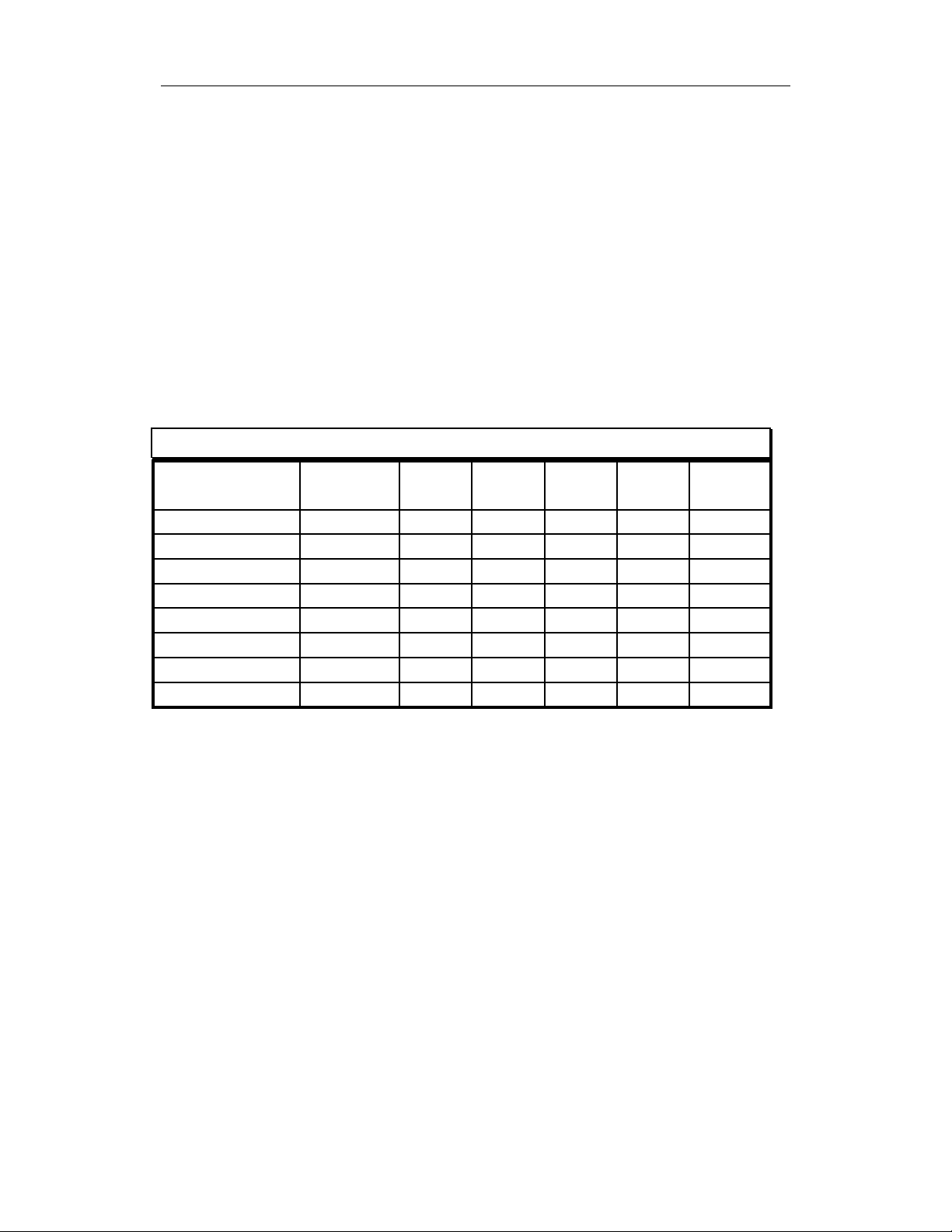
Factory Calibration and Preset Alarm Limits
Cal Gas Cal
Span
Isobutylene
Hexane, nXylene, mBenzene
Styrene
Toluene
Vinyl Chloride
Custom
unit
100 ppm 50 100 100 250
100 ppm 500 750 500 750
100 ppm 100 150 100 150
5 ppm 2 5 5 2
50 ppm 20 40 20 40
100 ppm 50 100 50 100
10 ppm 5 10 5 10
100 ppm 50 100 50 100
Low High TWA STEL
2-17
Page 31

OPERATION
2.7 Integrated Sampling Pump
The MiniRAE 2000 portable VOC monitor includes an
integrated sampling pump. This is a diaphragm type pump
that provides a 500-600 cc per minute flow rate.
Connecting a Teflon or metal tubing with 1/8 inch inside
diameter to the gas inlet port of the MiniRAE 2000, this
pump can pull in air samples from 200 feet away
horizontally, or 90 feet vertically, at about 3 feet per
second flow speed.
The pump turns on when a measurement is started, and
turns off when the sample is manually stopped in Survey
mode or when the unit is turned off from Hygiene Mode.
If liquid or other objects are pulled into the inlet port filter,
the monitor will detect the obstruction and shut down the
pump immediately. The alarm will be activated and a
flashing error message “Pump” will be also displayed on
the LCD display.
The user should acknowledge the pump shut off condition
by clearing the obstruction and pressing the [Y/+] key to
re-start the pump.
The pump stall threshold is set in the special Diagnostic
Mode (Section 8).
2-18
Page 32

OPERATION
2.8 Back Light
The LCD display is equipped with an LED back light to
assist in reading the display under poor lighting conditions.
Pressing and holding the [N/-] key for one second in
normal operation can turn on the backlight. The backlight
can be turned off by pressing [N/-] a second time. If the
[N/-] key is not pressed, the back light will be turned off
automatically after a pre-programmed time-out period to
save power.
In addition, the ambient light is sensed and the back light
will be turned on automatically if the ambient light is
below a threshold level. The back light is turned off
automatically when the ambient light exceeds the threshold
level.
See Section 8 for instructions on how to set the light
threshold level.
Note: The LED backlight consumes about 20-30% of the
total average current, when the instrument is idle or not
taking a measurement.
2-19
Page 33

OPERATION
2.9 Datalogging
During datalogging, the MiniRAE 2000 Portable VOC
monitor flashes a superscript “L”, on the display to
indicate that datalogging is enabled. The monitor stores the
time stamp, sample number, and measured gas
concentration at the end of every sample period (when data
logging is enabled). In addition, the following information
are stored: user ID, site ID, serial number, last calibration
date, and alarm limits. All data are retained (even after the
unit is turned off) in non-volatile memory so that it can be
down loaded at a later time to a PC.
Datalogging event
When Datalogging is enabled, measurement readings are
being saved. These data are stored in “groups” or “events.
A new event is created and stored each time the monitor is
turned on, or a configuration parameter is changed, or
datalogging is interrupted (e.g. Communication with PC
during Hygiene mode). Information, such as start time,
user ID, site ID, gas name, serial number, last calibration
date, and alarm limits will be recorded.
Datalogging sample
After an event is recorded, the unit records a shorter form
of the data. This data contains: the sample number, time
(hour/minute) and gas concentration.
2-20
Page 34

OPERATION OF ACCESSORIES
3. OPERATION OF ACCESSORIES
The accessories for the MiniRAE 2000 include:
• An AC Adapter (Battery Charger)
• Alkaline battery holder
• Water Trap Filter
Optional Accessories:
• Dilution Fitting
• Calibration adapter
• Calibration regulator and Flow controller
• Organic Vapor Zeroing kit
3-1
Page 35

OPERATION OF ACCESSORIES
3.1 Standard Kit and Accessories
1) AC Adapter (Battery Charger)
WARNING:
To reduce the risk of ignition of hazardous atmospheres,
recharge battery only in area known to be non-hazardous.
Remove and replace battery only in area known to be nonhazardous.
Ne charger les batteries que dans emplacements designés
non-dangereuses.
A battery charging circuit is built into the MiniRAE 2000
monitor. It only needs a regular AC to 12 V DC adapter
(wall mount transformer) to charge the monitor.
To charge the battery inside the MiniRAE 2000 monitor:
1. Power off the Monitor.
2. Connect the AC adapter (or the optional automotive
charging adapter) to the DC jack on the MiniRAE 2000
monitor. If the unit was off, it will automatically turn
on.
3. The first message displayed will be “Deep discharge?”
The unit will ask this question for three times. If the
user wants to discharge the battery pack, affirm this
query with the [Y/+] key, otherwise the unit will move
on to the charge mode directly.
3-2
Page 36

OPERATION OF ACCESSORIES
4. While charging, the display message will alternate
between “Charging” and “Bat=x.xV” (x.x is the present
battery voltage). The LED should be red in color when
charging.
Charging
5. When the battery is fully charged, the LED will change
from red to green and the message “Fully charged” will
appear on the display. After the battery is fully charged,
the unit will enter the “trickle charge” mode. In which,
the red LED will turn on for several seconds every
minute, to maintain the full charge.
A completely discharged MiniRAE 2000 monitor will be
charged to full capacity within 10 hours. The battery will
be drained slowly even if the monitor is turned off. If the
monitor has not been charged for 7-10 days, the battery
voltage will be low.
The factory-supplied battery is designed to last for 10
hours of normal operation (no alarm, no back light
condition), for a new battery under the best condition. As
the battery becomes older or is subject to adverse
conditions (such as cold ambient temperature), the battery
capacity will be reduced significantly.
3-3
Page 37

OPERATION OF ACCESSORIES
2) Alkaline Battery Holder
An alkaline battery holder is supplied with each MiniRAE
2000. It accepts four AA size alkaline batteries and can be
used in place of the Ni-MH or Ni-Cd battery pack to
provide approximately 12-14 hours of operation. The
adapter is intended to be used in emergency situations
when there is no time to charge the Ni-Cd or Ni-MH
battery pack.
To install the adapter, remove the cover of the battery
compartment. Remove the Ni-Cd or Ni-MH battery pack
from the battery compartment and replace with the alkaline
battery adapter. Replace the battery compartment cover.
The internal charging circuit is designed to prevent damage
to alkaline batteries and the charging circuit when alkaline
batteries are installed inside the monitor.
Note: The AA Alkaline battery adapter supplied by RAE
Systems Inc. is intrinsically safe!
3) Water Trap Filter
The water trap filter is made of PTFE (Teflon
) membrane
with a 0.45 micron pore size to prevent water from being
sucked into the sensor manifold, which would cause
extensive damage to the monitor. It will also remove any
dust and other particles from entering the monitor and
prolong the operating life of the sensor. To install the
water trap, simply insert it to the front of the inlet tube of
the MiniRAE 2000 monitor.
3-4
Page 38

OPERATION OF ACCESSORIES
3.2 Optional Accessories
1) Dilution Fitting
The user may wish to install a dilution fitting on the inlet
to dilute the gas samples. One application for a dilution
fitting is to measure organic gas when the concentration
exceeds the upper limit of the sensor range.
Make sure to set the dilution ratio in the programming
mode (see Section 4.7.9) so that the correct gas reading
will be displayed when the dilution fitting is used.
WARNING: To use a dilution fitting, the user
must have the monitor located in a clean
atmosphere outside the confined space and use a
remote access probe or Tygon tubing to measure
the gas concentration inside the confined space.
2) Calibration Adapter
The calibration adapter for the MiniRAE 2000 is a simple
6-inch Tygon tubing with a metal adapter on one end.
During calibration, simply insert the metal adapter into the
regular gas inlet probe of the MiniRAE 2000 and the
tubing to the gas regulator on the gas bottle.
3) Calibration Regulator and Flow Controller
The Calibration Regulator and Flow controller is used in
the calibration process. It regulates the gas flow rate from
the Span gas cylinder into the gas inlet of the MiniRAE
2000 monitor during calibration process. The maximum
flow rate allowed by the flow controller is about 0.5L/min
3-5
Page 39

OPERATION OF ACCESSORIES
(500 cc per min.). Alternatively, a Demand-flow
Regulator or a Tedlar gas bag may be used to match the
pump flow precisely.
4) Organic Vapor Zeroing kit (Charcoal filter)
The Organic Vapor Zeroing Kit is used for filtering
organic air contaminants that may affect the zero
calibration reading. To use the Organic Vapor Zeroing Kit,
simply connect the filter to the inlet port of the MiniRAE
2000.
3-6
Page 40

PROGRAMMING
4. PROGRAMMING OF MINIRAE 2000
The MiniRAE 2000 Monitor is built with a microcomputer
to provide programming flexibility. Authorized users can
re-calibrate the monitor, change the alarm limits, change
site ID, user ID, lamp type, and real time clock, etc.
Programming is menu-driven to provide intuitive end-user
operation. The display shows the menu options and the
key pad used for menu selection and data entry.
4-1
Page 41

PROGRAMMING
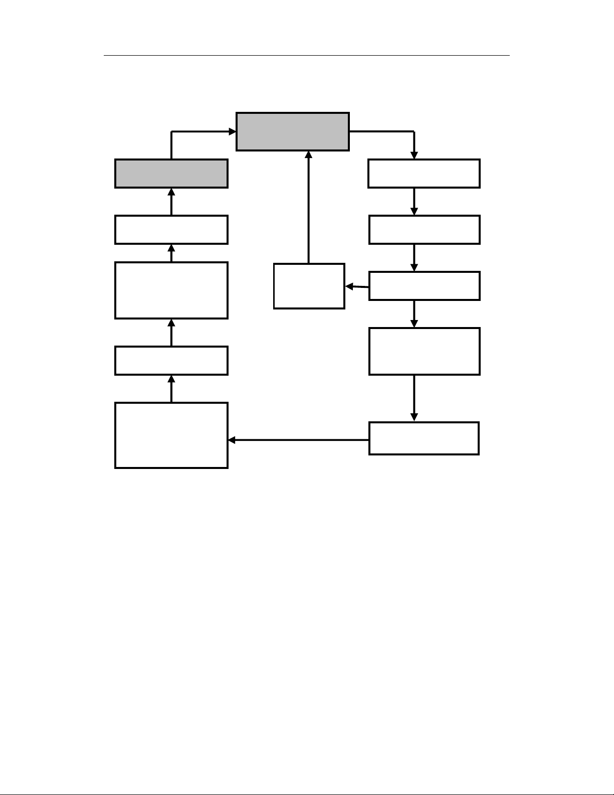
4.1 Programming Mode
The programming mode allows the users to change the
setups in the monitor, calibrate the monitor, modify the
sensor configuration and enter user information, etc. The
programming mode has four menu items. Each menu item
includes several sub-menus to perform additional
programming functions. Appendix A shows a more
detailed menu tree structure.
Calibrate/Select Gas?
Change Alarm Limits?
View or Change Datalog?
Change Monitor Setup?
Programming Menu
Once inside the programming mode, the LCD will display
the first menu. Each subsequent menu item can be viewed
by pressing the [N/-] repeatedly until the desired menu is
displayed. To enter the sub-menu of a particular menu,
press [Y/+] key, the sub-menu will be displayed.
Return to Operation mode: To exit the programming
mode and return to operation, press the [MODE] key once
at any of the programming menu displays.
4-2
Page 42

PROGRAMMING
4.2 Keys for Programming Mode
The three keys perform a different set of functions during
the programming mode as summarized below.
Key Function in Programming Mode
[MODE]: Exit menu when pressed momentarily or
exit data entry mode when pressed and
held for 1 second
[Y/+]: Increase alphanumerical value for data
entry or confirm (yes) for a question
[N/-]: Decrease alphanumerical value for data
entry or deny (no) for a question
4-3
Page 43

PROGRAMMING
4.3 Entering into Programming Mode
1. Turn on the MiniRAE 2000 monitor and wait for the
“Ready..” message or the instantaneous reading
display “0.0 ppm” message displayed.
2. Press and hold down both [N/-] and [MODE] keys for
three seconds to enter programming mode. This delay
is to prevent the user from entering programming mode
by accident.
3. The first menu item “Calibrate/select Gas?” will be
displayed.
4. Release both [MODE] and [N/-] keys simultaneously
to start the programming mode
5. Press [N/-] key to scroll to the next menu item of the
programming menu. Press [Y/+] key to select the
displayed menu item.
The following Sections 4.4 - 4.7 describe the details of
each menu options.
4-4
Page 44

PROGRAMMING
4.4 Calibrate and Select Gas
CAUTION WARNINGS:
The calibration of all newly purchased RAE Systems
instruments should be tested by exposing the sensor(s)
to known concentration calibration gas before the
instrument is put into service for the first time.
For maximum safety, the accuracy of the MiniRAE
2000 should be checked by exposing it to known
concentration calibration gas before each day’s use.
In the first menu of the programming mode, the user can
perform functions such as calibration of the MiniRAE
2000 Monitor, select default cal memories, and modify cal
memories (see Table 4.4).
Table 4.4
Calibrate/Select Gas Sub-Menu
Fresh Air Cal?
Span Cal?
Select Cal Memory?
Change Span Value?
Modify Cal Memory?
Change Correction Factor?
Calibrating the MiniRAE 2000 monitor is a two-point
process using “fresh air “ and the standard reference gas
(also known as span gas). First a “Fresh air” calibration,
which contains no detectable VOC (0.0 ppm), is used to set
the zero point for the sensor. Then a standard reference
4-5
Page 45

PROGRAMMING
gas that contains a known concentration of a given gas is
used to set the second point of reference.
Note: The span value must be set prior to calibrating for
fresh air or span.
The user can store calibrations for up to 8 different
measurement gases. The default gas selections are as
follows:
Cal Memory #0……Isobutylene
Cal Memory #1……Hexane
Cal Memory #2……Xylene
Cal Memory #3……Benzene
Cal Memory #4……Styrene
Cal Memory #5……Toluene
Cal Memory #6……Vinyl Chloride
Cal Memory #7……Custom?
Memory #0 functions differently than the other 7
memories. For Memory #0, isobutylene is always the
calibration gas. When the gas is changed in Memory #0 to
one of 100 other preprogrammed chemicals or to a userdefined custom gas, a correction factor is applied to all the
readings. During calibration, the unit requests isobutylene
gas and displays the isobutylene concentration
immediately following calibration, but when the unit is
returned to the normal reading mode, it displays the
selected gas and applies the correction factor.
The other 7 cal memories require the same calibration gas
as the measurement gas. These memories may also be
modified to a preprogrammed chemical or to a userdefined custom gas. In the gas library, only the gases that
4-6
Page 46

PROGRAMMING
can be detected by the installed UV lamp will actually be
displayed. Note that although the correction factor for the
new gas will be displayed and can be modified, this factor
is not applied when Memories #1-7 are used. Therefore
the factor will not affect the readings in these memories.
Once each of the memories has been calibrated, the user
can switch between the calibrated gases by changing the
cal memory without the need to recalibrate. Or the user
can switch the measurement gas in Memory #0 and the
appropriate correction factor will automatically be applied
without the need to recalibrate. If the gas is changed in
Memories #1-7, it is necessary to recalibrate.
To change a default gas from the list above to a library or
custom gas, first go to Select Cal Memory (Section 4.4.3)
and then proceed to Modify Cal Memory (Section 4.4.5) to
enter the desired gas. If the desired compound does not
appear in the preprogrammed library, the user can use the
Custom_VOC entry in the library, or the name and
correction factor of any of the existing compounds can be
changed as described in Section 4.4.5. A list of some 300
correction factors is given in Technical Note 106, available
at the website www.raesystems.com.
4-7
Page 47

PROGRAMMING
4.4.1 Fresh Air Calibration
This procedure determines the zero point of the sensor
calibration curve. To perform a fresh air calibration, use
the calibration adapter to connect the MiniRAE 2000 to a
“fresh” air source such as from a cylinder or Tedlar bag
(option accessory). The “fresh” air is clean dry air without
any organic impurities. If such an air cylinder is not
available, any clean ambient air without detectable
contaminant or a charcoal filter can be used.
1. The first sub-menu shows: “Fresh air Cal?”
2. Make sure that the MiniRAE 2000 is connected to one
of the “fresh” air sources described above.
3. Press the [Y/+] key, the display shows “zero in
progress” followed by “wait..” and a countdown timer.
4. After about 15 seconds pause, the display will show the
message “zeroed… reading = X.X ppm…” Press any
key or wait about 20 seconds, the monitor will return
back to “Fresh air Calibration?” submenu.
Note: The charcoal filter has a check box so that user can
mark off a box each time the filter has been used. The
charcoal filter should be replaced after 20 calibrations.
4-8
Page 48

PROGRAMMING
4.4.2 Span Calibration
This procedure determines the second point of the sensor
calibration curve for the sensor. A cylinder of standard
reference gas (span gas) fitted with a 500 cc/min. flowlimiting regulator or a flow-matching regulator is the
simplest way to perform this procedure. Choose the 500
cc/min. regulator only if the flow rate matches or slightly
exceeds the flow rate of the instrument pump.
Alternatively, the span gas can first be filled into a Tedlar
Bag, or delivered through a demand-flow regulator.
Connect the calibration adapter to the inlet port of the
MiniRAE 2000 Monitor, and connect the tubing to the
regulator or Tedlar bag.
Another alternative is to use a regulator with >500 cc/min
flow but allow the excess flow to escape through a T or an
open tube. In the latter method, the span gas flows out
through an open tube slightly wider than the probe, and
the probe is inserted into the calibration tube.
Before executing a span calibration, make sure the span
value has been set correctly (see next sub-menu).
1. Make sure the monitor is connected to one of the span
gas sources described above.
2. Press the [Y/+] key at the “Span Cal?” to start the
calibration. The display shows the gas name and the
span value of the corresponding gas.
3. The display shows “Apply gas now!” Turn on the
valve of the span gas supply.
4-9
Page 49

PROGRAMMING
4. Display shows “wait.... 30” with a count down timer
showing the number of remaining seconds while the
monitor performs the calibration.
5. To abort the calibration, press any key during the count
down. The display shows “Aborted!” and return to
“Span Cal?” sub-menu.
6. When the count down timer reaches 0, the display
shows the calibrated value.
Note: The reading should be very close to the span gas
value.
7. During calibration, the monitor waits for an increased
signal before starting the countdown timer. If a minimal
response is not obtained after 35 seconds, the monitor
displays “No Gas!” Check the span gas valve is on and
for lamp or sensor failure before trying again.
8. The calibration can be started manually by pressing any
key while the “Apply gas now!” is displayed.
9. After a span calibration is completed, the display will
show the message “Span Cal Done! Turn Off Gas.”
10. Turn off the flow of gas. Disconnect the calibration
adapter or Tedlar bag from the MiniRAE 2000
Monitor.
11. Press any key and it returns back to “Span Gas Cal?”
4-10
Page 50

PROGRAMMING
4.4.3 Select Cal Memory
This function allows the user to select one of eight
different memories for gas calibration and measurement.
For Memories #1-7, the calibration and measurement gas is
the same and no correction factor is applied. For Memory
#0, the calibration gas is always isobutylene and the
measurement gas may be different, in which case the
correction factor for that gas is automatically applied. The
default gas selections are listed in Section 4.4
1. “Select Cal Memory?” is the third sub-menu item in the
Calibration sub-menu. Pressing the [Y/+] key, the
display will show “Gas =” gas name followed by “Mem
# x?”
2. Press [N/-] to scroll through all the memory numbers
and the gas selections respectively. Press [Y/+] to
accept the displayed Cal Memory number.
3. After the [Y/+] key is pressed, the display shows
“Save?” Press [Y/+] key to save and proceed. Press
[N/-] to discard the entry and advance to the next submenu.
4. If the gas in a newly selected Cal Memory number is
not calibrated, the display shows “CF= x.xx”. A
correction factor with the value “x.xx” will be applied.
5. If the gas of a newly selected cal memory number has
been calibrated previously, the display shows “Last
calibrated xx/xx/xx”.
4-11
Page 51

PROGRAMMING
4.4.4 Change Span Value
This function allows the user to change the span values of
the calibration gases.
1. “Change Span Value?” is the fourth sub-menu item in
the Calibration sub-menu
2. Press [Y/+], display shows the gas name and the span
value. A cursor will blink at the first digit of the Span
value. To modify the span gas value, go to Step 3.
Otherwise, press and hold the [MODE] key for 1
second to accept the previously stored span gas value
and move to the next sub-menu.
3. Starting from the left-most digit of the span gas value,
use the [Y/+] or [N/-] key to change the digit value and
press [MODE] key momentarily to advance to next
digit. Repeat this process until all digits are entered.
Press and hold the [MODE] for 1 second to exit.
4. The display shows “Save?” To accept the new value,
press the [Y/+] key. Press the [N/-] key or the
[MODE] key to discard the change and move to the
next sub-menu.
4-12
Page 52

PROGRAMMING
4.4.5 Modify Cal Memory
If the current cal memory number selected is not memory
0, users will be prompted whether to modify the settings of
the selected cal memory. Press [Y/+] to modify the cal
memory and [N/-] to go to the next sub-menu.
Once [Y/+] is pressed the LCD display will show the
current memory number, current Gas selected and prompt
user for acceptance of current gas selected.
1. Press [N/-] to modify the gas selection if desired. Or
press [Y/+] key to skip the change of gas selection, and
proceed to the next sub-menu.
2. After pressing [N/-], display shows “Copy gas from
library?” Press [Y/+] to accept or [N/-] for the next
sub-menu, “Enter Custom gas?”
3. In the “Copy gas from library” submenu, use [Y/+] and
[N/-] keys to scroll through the selections in the library.
Press [MODE] key momentarily to select the gas. The
display shows ”Save?” Press [Y/+] to save or [N/-] to
discard the changes and proceed to next sub-menu.
4. In the Custom gas sub-menu, the user can enter the gas
name. Press the [Y/+] or [N/-] key to cycle through all
26 letters and 10 numerals. Press the [MODE] key
momentarily to advance to the next digit. The flashing
digit will move to the next digit to the right. Repeat
this process until all digits (up to 8 digits) of the custom
gas name is entered.
4-13
Page 53

PROGRAMMING
Press and hold the [MODE] key for 1 second to exit the
name entry mode. The display will show “Save?“ Press
[Y/+] to save the entry, or [N/-] to discard the changes.
4-14
Page 54

PROGRAMMING
4.4.6 Change Correction Factor
This function allows the user to change the Correction
Factor of the standard calibration gas (only for Cal
Memory #0).
1. “Change Correction Factor?” is the sixth sub-menu in
the Calibration sub-menu.
2. Press [Y/+] key. Display shows the gas name, then the
correction factor.
A cursor blinks at the left-most digit of the correction
factor. If user wants to modify the correction factor, go
to Step 3. Otherwise, press and hold the [MODE] key
for 1 second to accept the previously stored correction
factor value and return to the first sub-menu of the
calibrate/select gas menu.
3. Starting from the left-most digit of the correction
factor, use [Y/+] or [N/-] key to change the digit value
and press [MODE] key momentarily to advance to the
next digit, the cursor will move to the next digit to the
right. Repeat this process until all digits are entered.
Press and hold the [MODE] for 1 second to exit.
4. The display shows “Save?” To confirm the new value,
press [Y/+] to accept the change. Press [N/-] or
[MODE] to discard the change and return to the first
sub-menu, Calibrate and Select Gas.
4-15
Page 55

PROGRAMMING
4.5 Change Alarm Limits
In this menu, the user can change the high and low alarm
limits, the STEL limit and the TWA limit (see Table 4.5
below). Press the [Y/+] key and the display shows the
current gas selected followed by the first sub-menu item
below.
Table 4.5
Alarm Limit Sub-Menu
Change High Alarm limit?
Change Low Alarm limit?
Change STEL limit?
Change TWA limit?
1. Scroll through the Alarm Limit sub-menu using the
[N/-] key until the display shows the desired limit to be
changed, e.g.,”High limit?”, “STEL limit?”, etc.
2. Press the [Y/+] key to select the desired limit and the
display shows a flashing cursor on the left-most digit of
the previously stored alarm limit.
4-16
Page 56

PROGRAMMING
0010.0
3. To modify this limit value, use the [Y/+] or [N/-] key to
change the digit value and press the [MODE] key
momentarily to advance to the next digit. The flashing
digit will move to the next digit to its right. Repeat this
process until the new limit value is entered. Press and
hold the [MODE] key for 1 second to exit data entry
mode.
4. If there is any change to the existing value, the display
shows “Save?” Press [Y/+] to accept the new value
and move to the next sub-menu. Press [N/-] to discard
the changes and move to the next sub-menu.
4-17
Page 57

PROGRAMMING
4.5.1 Change Low Alarm Limit
The second sub-menu item in the Alarm Limit sub-menu
allows the user to change the Low Alarm limit. The LCD
displays “Low limit?” To change Low Alarm limit, press
[Y/+] key, or Press [N/-] key advance to next sub-menu in
Table 4.5.
1. Press [Y/+] and the display will show a flashing cursor
on the left-most digit of the previously stored Low
alarm limit.
2. To modify this limit value, use the [Y/+] or [N/-] key
to change the digit value and press the [MODE] key
momentarily to advance to the next digit. The flashing
digit will move to the next digit to its right. Repeat
this process until the new limit values is entered. Press
and hold the [MODE] key for 1 second to exit data
entry mode.
3. If there is any change to the existing value, the display
shows “Save?” Press [Y/+] to accept the new value
and move to the next sub-menu. Press [N/-] to discard
the changes and move to the next sub-menu.
4-18
Page 58

PROGRAMMING
4.5.2 Change STEL Limit
This sub-menu item allows the user to change the STEL
limit. The display shows “STEL limit?”
1. Press the [Y/+] key and the display will show a
flashing cursor on the left-most digit of the previously
stored STEL limit.
2. To modify this limit value, use the [Y/+] or [N/-] key
to change the digit value and press the [MODE] key
momentarily to advance to the next digit. The flashing
digit will move on to next digit to its right. Repeat this
process until the new limit values is entered. Press and
hold the [MODE] key for 1 second to exit data entry
mode.
3. If there is any change to the existing value, the display
shows “Save?” Press [Y/+] to accept the new value
and move to the next sub-menu. Press [N/-] to discard
the changes and move to the next sub-menu.
4-19
Page 59

PROGRAMMING
4.5.3 Change TWA Limit
This sub-menu item allows the user to change the TWA
limit. The LCD displays “TWA limit?”
1. Press [Y/+] and the display will show a flashing cursor
on the left-most digit of the previously stored TWA
limit.
2. To modify this limit value, use the [Y/+] or [N/-] key
to change the digit value and press the [MODE] key
momentarily to advance to the next digit. The flashing
digit will move on to next digit to its right. Repeat this
process until the new limit values is entered. Press and
hold the [MODE] key for 1 second to exit data entry
mode.
3. If there is any change to the existing value, the display
shows “Save?” Press [Y/+] to accept the new value
and move to the next sub-menu. Press [N/-] to discard
the changes and move to the next sub-menu.
4-20
Page 60

PROGRAMMING
4.6 View or Change Datalog
The MiniRAE 2000 monitor calculates and stores the
concentration and ID of each sample taken. In the datalog
sub-menu, a user can perform the tasks and functions
shown in Table 4.6.
Table 4.6
Datalog Sub-Menu
Reset Peak/Minimum?
View Data?
Clear Data?
Change Data Period?
Change Average Type?
4-21
Page 61

PROGRAMMING
4.6.1 Reset Peak/Minimum
This function will reset the peak and minimum stored in
the data memory. Note: this function will not clear the
STEL or TWA data.
1. “Reset Peak/Minimum?” is the first sub-menu item in
the Datalog sub-menu (Table 4.6).
2. Press the [Y/+] key to reset the Peak/Minimum Values.
The display shows “Are You Sure?”
3. Pressing the [Y/+] key again will reset the values. The
display shows “Peak/Minimum Cleared” and moves to
the next submenu.
4. Press the [N/-] or [MODE] key to exit without resetting
the values and move to the next sub-menu.
4-22
Page 62

PROGRAMMING
4.6.2 View Data (Datalog)
This function allows the user to review all the data that is
stored in the non-volatile datalog memory.
Data are stored in groups, or “events”. Each event consists
of event time (hour:minute:seconds), and measurement
values. For example:
Event/Log #1
Data #1 (10/01/97, 14:35:05, Avg., 0.2 PPM, Max 4.0)
Data #2 (14:35:10, Avg. 0.4, Max 11.0)
Data #3 (14:35:15, Avg. 0.4, Max 11.0)
Event/Log #2
Data #1 (10/03/98, 07:20:30 ,Avg. 3.4, Max 20.0)
Data #2 (07:20:40, Avg. 0.7, Max 20.0)
1. “View Data?” is the second sub-menu item in the
Datalog sub-menu.
2. Press the [Y/+] key and the display shows “Event..”
Log # 1?
and “Log #1?” Press the [Y/+] key to view the data of
the displayed event. Or press the [N/-] key to scroll to
next event. If there are no more events, the message
“No more events! Start from event #1?” will appear.
4-23
Page 63

PROGRAMMING
Press [Y/+] and the monitor will return to the first
event. Press [N/-] and the monitor will remain in the
last event.
3. Press [Y/+] to review the first data of the selected
event. The display shows the stored data including the
time stamp in hours and minutes, and measurement
values.
Action Display
Event, Log# 1?
[Y/+] 10/01/97, 14:20:07, Avg. 2.0, Max 3.3
[Y/+] 14:20:08, Avg. 2.0, Max 3.4
4. Press the [Y/+] or [N/-] key to move forward or
backward to view other data from this event. When the
beginning or the end of the event is reached, the
message “1st data” or “End data” will appear. Press the
[MODE] key to exit the current event.
4-24
Page 64

PROGRAMMING
4.6.3 Clear Data
This function will erase all data stored in the non-volatile
datalog memory. Note: This function does not change
STEL, TWA, Peak, Minimum and run time values, which
are stored in the regular data memory.
1. “Clear Data?” is the third sub-menu item in the Datalog
sub-menu.
2. Press the [Y/+] key to clear the datalog memory. The
display shows “Are you sure?”
3. Press the [Y/+] key again to confirm erasure of all the
datalog memory.
4. Press the [N/-] or [MODE] key to exit without
clearing the datalog memory and move to the next datalog
sub-menu.
4-25
Page 65

PROGRAMMING
Change Data Period
The datalog period can be programmed from 1 to 3,600
seconds (1 hour).
1. “Change Data Period?” is the fifth sub-menu item in
the Datalog sub-menu.
2. Press the [Y/+] key and the display shows “Datalog
Period = XXXX” with the left-most digit flashing,
where “XXXX” is the previously stored data log
period.
4. To modify this period, starting from the left-most digit,
use the [Y/+] or [N/-] key to change the digit value and
press the [MODE] key momentarily to advance to the
next digit. The flashing digit will move to the next
digit to the right. Repeat this process until all 4 digits
of the new period are entered. Press and hold the
[MODE] key for 1 second to exit data entry mode.
5. If there is any change to the existing value, the display
will show “Save?” Press [Y/+] to accept the new value
or [N/-] to discard the changes and move to the next
sub-menu.
4-26
Page 66

PROGRAMMING
4.6.5 Change Average Type
The user can select either an 8-hour Time Weighted
Average (TWA) or a running Average. The running
average is simply the average of all instantaneous (1second) readings since the measurement was started. This
average may increase or decrease with time depending on
the readings. The TWA is a cumulative value used to
estimate the fraction of the 8-hour limit to which the user
has been exposed since the start of the measurement. This
value can only increase or remain constant, never decrease.
Refer to Technical Note 119 for more information on how
TWA is calculated.
1. “Change Average Type?” is the sixth sub-menu in the
Datalog sub-menu.
2. Press the [Y/+] key to enter the function.
3. The display will show “Running Average?” or “ Time
Weighted Average?” depending on the current average
type.
4. Press [N/-] key to toggle between the average types.
Press [Y/+] key to select the displayed average type.
5. If there is any change to the existing setting, the display
shows “Save?” Press [Y/+] to save the change. Press
[N/-] or [MODE] to discard the change and return to
the first sub-menu.
4-27
Page 67

PROGRAMMING
4.7 Change Monitor Setup
Several monitor specific variables can be changed in this
menu. The following is a list of configuration data that can
be modified by the user.
Table 4.7
Monitor Setup Sub-Menu
Change Operation Mode?
Change Site ID?
Change User ID?
Change Alarm Mode?
Change User Mode?
Change Date?
Change Time?
Change Lamp?
Change Unit?
Change Dilution Ratio?
Change Output?
Change DAC Range?
Set Temperature Unit?
4-28
Page 68

PROGRAMMING
4.7.1 Change Operation Mode
MiniRAE 2000 supports two operation modes: Survey and
Hygiene mode.
Survey mode: Manual start/stop of measurements and
display of certain exposure values.
Hygiene mode: Automatic measurements, running and
datalogging continuously and calculates additional
exposure values.
1. “Change Op Mode?” is the first sub-menu item in the
Monitor Setup menu (Table 4.7).
2. Press the [Y/+] key and the display shows the current
user mode: “Op Mode = current mode?”
3. Press the [Y/+] key to accept the currently displayed
operation (Op) mode. Press [N/-] to toggle to the other
operation mode. Press [MODE] to exit this sub-menu
and move to the next monitor setup sub-menu.
4. When changing Op mode from Hygiene to Survey, the
display shows the additional message “Warning! Exit
Hygiene?” to prevent accidental exit from Hygiene
mode. Press the [Y/+] key to acknowledge.
5. If there is any change to the existing setting, the display
will show “Save?” Press the [Y/+] key to accept or the
[N/-] key to discard and move to the next sub-menu.
Note: If a new Op Mode is saved, the display shows “Op
Mode changed!!” when exiting the programming mode.
4-29
Page 69

PROGRAMMING
4.7.2 Change Site ID
The user can enter an 8-digit alphanumeric site ID in the
programming mode. This site ID will be included in the
datalog report.
1. “Change Site ID?” is the second sub-menu item in the
Monitor Setup menu (Table 4.7).
2. Press the [Y/+] key and the display shows the current
site ID: “Site ID = xxxxxxx” with the left most digit
flashing.
3. Press the [Y/+] or [N/-] key to cycle through all 26
letters and 10 numerals. Press [MODE] momentarily
to advance to the next digit. The flashing digit will
move to the next digit to the right. Repeat this process
until all 8 digits of the new site ID are entered.
4. Press and hold the [MODE] key for 1 second to exit the
data entry mode.
5. If there is any change to the existing site ID, the display
shows “Save?” Press the [Y/+] key to accept the new
site ID. Press the [N/-] key to discard the change and
move to the next sub-menu.
4-30
Page 70

PROGRAMMING
4.7.3 Change User ID
The user can enter an 8-digit alphanumeric user ID in the
programming mode. This user ID will be included in the
datalog report.
1. “Change User ID?” is the third sub-menu item the
Monitor Setup menu.
2. Press the [Y/+] key and the display shows the current
user ID: “User ID = xxxxxxxx” with the left most digit
flashing.
3. Press the [Y/+] or [N/-] key to cycle through all 26
letters and 10 numerals. Press [MODE] momentarily
to advance to the next digit. The flashing digit will
move to the next digit to the right. Repeat this process
until all 8 digits of the new user ID are entered.
4. Press and hold the [MODE] key for 1 second to exit the
data entry mode.
5. If there is any change to the existing user ID, the
display shows “Save?” Press the [Y/+] key to accept
the new user ID. Or press the [N/-] key to discard the
changes and move to the next sub-menu.
4-31
Page 71

PROGRAMMING
4.7.4 Change Alarm Mode?
There are two different alarm modes: Latched and
Automatic Reset (Auto Reset) in the MiniRAE 2000 that
can be selected from the programming menu.
1. “Change Alarm Mode?” is the fourth sub-menu item in
the Monitor Setup menu.
2. Press the
mode.
3. Press the [Y/+] key to accept the currently displayed
alarm mode. Press [N/-] key to toggle to the other
alarm mode. Press [MODE] to exit this sub-menu and
move to the next monitor setup sub-menu.
4. If there is any change to the existing setting, the display
will show “Save?” Press [Y/+] to save the change.
Press [N/-] or [MODE]
to the next sub-menu.
[Y/+] key; the display shows the current alarm
to discard the change and move
4-32
Page 72

PROGRAMMING
4.7.5 Change User Mode
There are two different user modes: Display and Program
that can be selected from the programming menu.
1. “Change User Mode?” is the fifth sub-menu item in the
Monitor Setup menu (Table 4.7).
2. Press the [Y/+] key; the display shows the current user
mode selected.
3. Press the [Y/+] key to accept the currently displayed
user mode. Press [N/-] key to toggle to the alternate
user modes. Press [MODE] to exit this sub-menu and
move to the next monitor setup sub-menu.
4. If there is any change to the existing selection, the
display shows messages “Program change” and “Are
you sure?” Press [Y/+] to confirm the change or press
[N/-] or [MODE] to discard the changes and move to
the next sub-menu.
CAUTION: If the user mode is changed to Display mode,
the user can no longer enter the programming mode.
Therefore, the user can not change the user mode back to
Program mode in normal mode.
To restore the user mode back to Program mode, turn the
unit off and back on in Diagnostic Mode. Next enter
Program mode by holding the [MODE] and [N/-] keys for
three seconds. Enter the password at the prompt (the
default is 0000). Once program mode is entered, go to the
“Change Monitor Setup” / “Change User Mode” and
change the mode back to Program.
An alternative way to change Display mode back to
Program mode is through the PC and the ProRAE-Suite
software (see Section 5.5.1).
4-33
Page 73

PROGRAMMING
4.7.6 Change Date
The MiniRAE 2000 monitor is equipped with a real time
clock (RTC). The user can enter the correct date and time
(see 4.7.7) for the real time clock.
1. “Change Date?” is the sixth sub-menu item in the
Monitor Setup menu.
2. Press [Y/+] and the display shows the current date
“mm / dd / yy” with the left most digit of the date
flashing.
5. To modify this value, use the [Y/+] or [N/-] key to
change the digit value and press the [MODE] key
momentarily to advance to the next digit. The flashing
digit will move on to next digit to its right. Repeat this
process until the new date and time values are entered.
Press and hold the [MODE] key for 1 second to exit
data entry mode.
4. If there is any change to the existing value, the display
shows “Save?” Press [Y/+] to confirm the new value or
press [N/-] or [MODE] to discard the changes and
move to the next sub-menu.
4-34
Page 74

PROGRAMMING
4.7.7 Change Time
To change the time in the RTC of the MiniRAE 2000:
1. “Change Time?” is the seventh sub-menu item in the
Monitor Setup menu.
2. Press [Y/+] and the display shows the current time in
the 24-hour format “hh : mm” with the left most digit
of the time flashing.
3. To modify this value, use the [Y/+] or [N/-] key to
change the digit value and press the [MODE] key
momentarily to advance to the next digit. The flashing
digit will move on to next digit to its right. Repeat this
process until the new date and time values are entered.
Press and hold the [MODE] key for 1 second to exit
data entry mode.
4. If there is any change to the existing value, the display
shows “Save?” Press [Y/+] to confirm the new value or
press [N/-] or [MODE] to discard the changes and
move to the next sub-menu.
4-35
Page 75

PROGRAMMING
4.7.8 Change Lamp
There are three UV lamps with different photon energies
available for the PID sensor: 9.8 eV, 10.6 eV and 11.7
eV. The user can select any one of the lamps from the
programming mode.
1. “Change Lamp Type?” is the eighth sub-menu item in
the Monitor Setup menu (Table 4.7).
2. Press the
[Y/+] key; the display shows the current PID
lamp selection.
3. Press the [Y/+] key to accept the currently displayed
lamp. Press [N/-] key to scroll through the sub-menu
for other lamp selections. Press [MODE] to exit this
sub-menu and return to the next sub-menu in Table 4.7.
4. If there is any change to the existing selection, the
display will show “Save?” Press
selection or press
[N/-] or [MODE] to discard the
[Y/+] to save the new
change and return to the next sub-menu in Table 4.7.
4-36
Page 76

PROGRAMMING
4.7.9 Change Unit
User can change the display and datalog unit from parts
per million (ppm) to milli-gram per cubic meter (mg/m
1. “Change Unit?” is the ninth sub-menu item in the
Monitor Setup sub-menu.
2. Press the [Y/+] key, the display should show the current
unit “Display Unit = ppm?” or “Display Unit = mg?”
3. Press [Y/+] key to accept the currently displayed unit.
Press [N/-] key to toggle to the other unit. Press
[MODE] key to exit this sub-menu.
4. If there is any change to the existing selection, press
3
).
[Y/+] to confirm the new selection or press [N/-] or
[MODE] to discard the changes and move to the next
sub-menu.
Caution:
1. The correction factor in the gas library is calculated
based on “ppm” unit. If “mg” unit is selected, the
built-in correction factor library is not valid.
2. No automatic conversion between “ppm” and
3
“mg/m
” reading is performed by the monitor.
3. When the unit name is changed from “ppm” to
“mg”, the unit must be recalibrated with the span
3
gas concentration entered in mg/m
. The converse
rule applies when the unit is changed from “mg” to
“ppm”.
4-37
Page 77

PROGRAMMING
4.7.10 Change Dilution Ratio
If a dilution system is used upstream of the MiniRAE 2000
inlet port, the user can enter the dilution ratio (from 1 to
10) to compensate the readings. The unit will then display
the actual concentration of the gas before dilution. The
dilution ratio should be 1 in normal operation where no
dilution gas is applied to the sample gas. Dilution
improves accuracy and linearity when the concentrations
are above a few thousand ppm.
1. “Change Dilution Ratio?” is the tenth sub-menu item in
the Monitor Setup menu.
2. Press the
[Y/+] key; the display shows the current
dilution ratio: “Dilution Ratio = xx” with the left most
digit flashing.
3. Press the [Y/+] or [N/-] key to increase or decrease the
value of the digit. Press [MODE] momentarily to
advance to the next digit. The flashing digit will move
to the next digit to the right. Repeat this process until
both digits of the new dilution ratio are entered.
4. Press and hold the [MODE] key for 1 second to exit the
data entry mode and move to the next sub-menu.
5. If there is any change to the existing dilution ratio, the
display shows “Save?” Press [Y/+] to confirm the new
value or press [N/-] or [MODE] to discard the changes
and move to the next sub-menu.
4-38
Page 78

PROGRAMMING
4.7.11 Change Output?
There are two different external output options: DAC
(Analog output) and Alarm in the MiniRAE 2000 that can
be selected from the programming menu. The alarm output
can be used to connect to the optional vibration alarm
(vibrator) only. The analog output, which is proportional
to the gas concentration, can be connected a chart recorder
or can be queried by a computer to download data in real
time (see Technical Note 141).
1. “Change External Output?” is the eleventh sub-menu
item in the Monitor Setup menu.
2. Press the
[Y/+] key and the display shows the current
output option selection: “Output = DAC?”
3. Press the [Y/+] key to accept the currently displayed
output option. Press [N/-] to change to the other
external option: “Output = Alarm?” Press [MODE] to
exit this sub-menu and move to the next monitor setup
sub-menu.
4. If there is any change to the existing selection the
display will show “Save?” Then, press [Y/+] to save
the change, press [N/-] to go back to Step 2, or press
[MODE] to exit this sub-menu and move to the next
monitor setup sub-menu.
4-39
Page 79

PROGRAMMING
4.7.12 Change DAC Range?
There are four different DAC (Digital-to-Analog
Conversion) range values available in the MiniRAE 2000:
20, 200, 2000 and 10K ppm. The maximum 2.5V DC
analog signal output from the unit will represent the range
value chosen. (See Figure 8-1 Communication/Alarm
Connector for analog signal output connection.)
1. “Change DAC Range?” is the twelfth sub-menu item in
the Monitor Setup menu.
2. Press the
[Y/+] key, the display shows the current DAC
Range value: “DAC Range = 2000 ppm?”
3. Press the [Y/+] key to accept the currently displayed
value. Press [N/-] to scroll through the sub-menu for
other range values. Press [MODE] to exit this submenu and return to the first sub-menu in Table 4.7.
4. If there is any change to the existing selection, press the
[Y/+] key and the display will show “Save?” Press the
[Y/+] key to save the change or press the [N/-] key to
discard and return to the first sub-menu in Table 4.7.
4-40
Page 80

PROGRAMMING
4.7.13 Set Temperature Unit?
The temperature display can be switched between
Fahrenheit and Celsius units.
1. “Set Temperature Unit?” is the thirteenth sub-menu
item in the Monitor Setup menu.
2. Press the
[Y/+] key, and the display shows the current
setting: “Temperature Unit = Fahrenheit?”
3. Press the [Y/+] key to accept the currently displayed
value. Press [N/-] to select the sub-menu “Temperature
Unit = Celsius?” Press [MODE] to exit this sub-menu
and return to the first sub-menu in Table 4.7.
4. If there is any change to the existing selection, press the
[Y/+] key and the display will show “Save?” Press the
[Y/+] key to save the change and return to the first sub-
menu in Table 4.7 or press the
[N/-] key to discard and
return to Step 3..
4-41
Page 81

PROGRAMMING
4.8 Exit Programming Mode
1. To exit programming mode from the first tier menu
level, press the [MODE] key once.
2. To exit programming mode from 2nd tier sub-menu,
press the [MODE] key twice.
3. To return to programming mode, press and hold down
both the [MODE] and [N/-] keys for 3 seconds.
4-42
Page 82

COMPUTER INTERFACE
5. COMPUTER INTERFACE
Each MiniRAE 2000 is shipped with a software package,
called ProRAE-Suite, and a serial computer interface
cable.
This software package runs on any IBM compatible
Personal Computer (PC) under Windows 95
98
, Windows 2000, Windows NT 4.0, Windows ME,
and later environments. It allows the user to configure
the MiniRAE 2000 through a user-friendly interface and
send the configuration information from the PC to the
, Windows
MiniRAE 2000 monitor. Collected data can also be
extracted from the MiniRAE 2000 to the PC in order to
perform data analysis, report generation or record
keeping. Installation and operation of this software
package is described in the following Sections.
Note: The monitor does not need to be equipped with
datalogging capability to use the ProRAE-Suite computer
interface package.
5-1
Page 83

COMPUTER INTERFACE
5.1 Installing ProRAE-Suite Software
The ProRAE-Suite software package is available on 3.5”
setup diskettes or can be downloaded from the website
www.raesystems.com. To install the ProRAE-Suite
software from a diskette, insert the first setup diskette into
the “A” or “B” floppy disk drive. Click the Start button
on the taskbar to display the start menu, then click the
Run from the start menu to display the Run dialog box.
If the setup diskette is in disk drive A, type A:\Setup.exe
in the Open field, as shown in Figure 5-1.
Figure 5-1 Run Dialog Box
Press the Enter key on the keyboard or click the OK
button on the Run datalog box to start the setup process.
If the user chooses the default settings in every step of the
process, the ProRAE-Suite software will be installed
under the default directory: C:\Program Files\RAE
Systems Inc\ProRAE-Suite. After the software is
installed successfully, a new menu item ProRAE-Suite is
added to the Programs menu. To start the ProRAE-Suite
software, click the Start button on the taskbar to display
the Start menu, click the Programs menu item to display
5-2
Page 84

COMPUTER INTERFACE
the Programs submenu, then click the ProRAE-Suite
menu item to display the ProRAE-Suite submenu. There
are two submenu items under the ProRAE-Suite
submenu: ProRAE-Suite and Readme, as shown in
Figure 5-2. Click the ProRAE-Suite submenu item to
start the ProRAE-Suite software.
Figure 5-2 Start Menu
5-3
Page 85

COMPUTER INTERFACE
5.2 Connect MiniRAE 2000 to PC
The basic kit of the MiniRAE 2000 is supplied with a
serial interface cable. Connect the DB-9 connector side of
the cable to the serial port of the PC, and connect another
side of the cable to the MiniRAE 2000 monitor.
Turn on the power to the MiniRAE 2000 monitor. Press
the [MODE] key several times until the LCD shows “PC
comm?” Press the [Y/+] key and the display shows
“Pause monitor, OK?” Press [Y/+] to confirm and the
display shows “Comm....” to indicate that the MiniRAE
2000 monitor is ready and waiting for communication
with the PC. During the communication session, the PC
will directly control the MiniRAE 2000 monitor through
the serial link. There is no need to press any key on the
MiniRAE 2000 monitor during the communication
session.
If no data transfer has occurred within two minutes, the
MiniRAE 2000 monitor will return to instantaneous
reading display.
Note: Do not connect to the parallel port of the PC by
mistake. The parallel port is usually a 25 pin female D
connector on the back of the PC, the serial port is usually
a 25 or 9 pin male D connector. If the serial port on the
PC is a 25-pin connector, the user needs to use a 25 pin to
9-pin adapter in order to accept the serial cable.
5-4
Page 86

COMPUTER INTERFACE
5.3 Start ProRAE-Suite Software
To start the ProRAE-Suite software, click the Start
button on the taskbar to display the Start menu, then
click the Programs -> ProRAE-Suite -> ProRAE-Suite
submenu item to start the ProRAE-Suite software. Figure
5-3 shows the main window of the ProRAE-Suite
software
Figure 5-3 ProRAE-Suite Main Window
.
The functions of the ProRAE-Suite software can be
divided into three categories:
1) Configuration data category. This category includes
editing the configuration data file, sending the
configuration data to the MiniRAE 2000 monitor and
receiving the configuration data from the MiniRAE
2000 monitor, etc.
2) Logged data category. This category includes
receiving logged data from the MiniRAE 2000
monitor, displaying logged data in different format,
5-5
Page 87

COMPUTER INTERFACE
and exporting logged data to a tab delimited text file
so that it can be read by a spreadsheet program such as
Microsoft Excel, etc.
3) Upgrade category. This category includes upgrading
the monitor to datalogging capability, and upgrading
the firmware in the monitor.
There is a tool bar beneath the menu bar. The frequently
used functions are represented in this tool bar in the form
of a small icon. For example, the Receive data function
in the Communication sub-menu is represented as a
small arrow with the letters “RECV”. When the mouse
cursor (a small arrow) is positioned near each icon in the
tool bar, a short text will also appear at the bottom of the
Window to describe the function of this icon.
This tool bar allows the user to invoke a function
conveniently by clicking on the icon without going
through the sub-menus.
5-6
Page 88

COMPUTER INTERFACE
5.4 Setup Communication Port
It is necessary to setup the communication port on the
ProRAE-Suite software so that the MiniRAE 2000
monitor can communicate with the PC correctly. Figure
5-4 shows the Setup Port dialog box. Choose the
appropriate port according to the PC’s serial port setup.
Figure 5-4 Setup Port Dialog
Note: In most PC's, there are two serial ports. Make sure
that the serial port selected in the Setup Port dialog box
matches the actual serial port connected to the MiniRAE
2000 monitor. The default serial port for ProRAE-Suite
is COM1. If the incorrect serial port is selected, an error
message of “error occur during serial port initialization”
will appear when a user tries to communicate between the
PC and the MiniRAE 2000 monitor.
5-7
Page 89

COMPUTER INTERFACE
5.5 Processing the Configuration Data
The ProRAE-Suite software allows the user to edit the
configuration data, send the configuration data to the
MiniRAE 2000 monitor, and receive the configuration
data from the MiniRAE 2000 monitor. The following
sub-sections describe the details of each operation.
5-8
Page 90

COMPUTER INTERFACE
5.5.1 Editing the Configuration Data
There are two different sources of the configuration files.
One is loaded from the unit, the other is from a
configuration file previously saved on the PC.
To load and review the configuration of the monitor:
From the main menu of the ProRAE-Suite software,
select the Receive Configuration… menu item from the
Communication dropdown menu, then click the OK if
the unit is connected to the communication port and
ready.
To load a saved configuration file: From the main
menu, select Open from the File… dropdown menu, a
dialog box appears. Select the “Files of type:” to Config
Files[ *.cfg], as shown in Figure 5-5.
Figure 5-5 Open Dialog Box
5-9
Page 91

COMPUTER INTERFACE
There should be one or more configuration files in the file
list. Each configuration file has a file extension of
“.CFG”. There is one generic MiniRAE 2000
configuration file supplied with ProRAE-Suite software:
Default_MiniRAE2000_V###.CFG, where ### is the
version number of the default configuration file. For
example, Default_MiniRAE2000_V200.cfg means this
file is for MiniRAE 2000 monitor and its version is
V2.00. Choose a configuration file by highlighting the file
name and press the Enter key or click the Open button
on the dialog box.
Once the configuration file is open, the configuration data
are displayed in the newly opened client window, as
shown in Figure 5-6.
Figure 5-6 Displayed Configuration Data
5-10
Page 92

COMPUTER INTERFACE
To edit the opened configuration data file, click the Edit -
> Configuration menu item or the Configuration toolbar
button to open the Edit Configuration File dialog box,
as shown in Figure 5-7. After editing the settings, click
the OK button to close the Edit Configuration File
dialog box. The new values of the configuration settings
will be reflected in the client window.
Figure 5-7 Edit Configuration File Dialog Box
The General tab page, which is shown in Figure 5-7,
allows the user to change the general configuration
settings. The following is the description of each field in
the General tab page of the Edit Configuration File
dialog:
5-11
Page 93

COMPUTER INTERFACE
ID:
This Section sets the identification that is used throughout
the datalog process. Both editing fields, Site and User,
can hold up to eight alphanumeric letters.
Security Level:
There are three levels of security. Use security level to
provide protection against unauthorized changes to the
monitor settings in the programming mode.
Level 0 allows the user to enter the programming menu
without password checking, but does not allow changes to
alarm limits, real time clock, correction factor, or user and
site information, etc. The user can still perform
calibrations.
If Level 1 is selected, a four-digit password is required to
enter the programming menu.
If Level 2 is selected, the programming menu may be
entered without restriction. Any changes made in the
programming menu can be saved.
Password:
Entry to the programming menu requires the four-digit
password be punched in if Level 1 is selected as the
security level.
User Mode:
In the Display mode, the user can view several readings
in the normal operation, but can not enter the
programming menu. In the Program mode, the user can
enter the programming mode to calibrate the monitor or
change various setups in the monitor.
5-12
Page 94

COMPUTER INTERFACE
Operation Mode:
There are two operation modes the user can set: Hygiene
and Survey mode. Hygiene mode is a continuous
measurement mode. Survey mode is a manual start and
stop measure mode. See chapter 2 for more details on the
Hygiene and Survey mode.
Warm-up Time:
This option allows the user to choose the warm-up time of
the instrument, in seconds.
Comfort Beep:
This option allows the user to specify a time interval that
the buzzer will beep once to remind the user that the
monitor is on. If zero is entered for the time interval, then
the comfort beep feature is disabled.
Back Light:
This option allows the user to enter a time out period so
that the back light will be turned off automatically after
the time out period.
Clock from PC:
This option allows the PC clock to be downloaded to the
MiniRAE 2000 monitor so that the user does not need to
manually set the clock in the MiniRAE 2000 monitor.
Alarm Mode:
This option allows the alarm to be either latched or autoreset. Selecting the auto-reset option allows the monitor
to turn off alarms when the alarm situation is no longer
exist. The latched option allows the alarm to stay on as
long as the alarm situation is no longer exist and a key is
pressed to acknowledge the alarm situation.
5-13
Page 95

COMPUTER INTERFACE
Power On Zero:
This option allows the monitor to perform a fresh air
calibration automatically when the monitor is turned on.
Care must be taken, when using this mode, to ensure that
the monitor is in a fresh air environment and the unit has
been warmed up when turned on.
Datalog Interval:
The datalog interval is the rate at which datalog samples
are recorded while the datalog is running. The unit of
datalog interval is second. The datalog interval
determines how often a new sample is calculated and
stored to the datalog.
Datalog Selection:
User can choose one or more values for datalogging
purpose. User can choose to datalog the minimum,
average, and maximum values, or any combinations of
the three values.
Datalog Mode:
This may be set to either of four choices:
-- With Automatic start/stop, the datalogging begins
when the monitor is turned on and ends when it is turned
off.
-- With Manual start/stop, the datalog can begin by a
series of key presses in the menu of normal operation.
The maximum run time determines an automatic end to
the datalog or it can be stopped manually.
-- If Periodic start /stop (or daily) mode is chosen, the
user must specify the start and stop hour and minute. The
interval between start and stop is the period of time the
monitor will datalog (at “datalogging period” rate).
5-14
Page 96

COMPUTER INTERFACE
-- With Scheduled start/stop, all the entry boxes for
year, month, day, hour and minute for both start and stop
time must be entered to specify when the datalog is to
occur.
Run Time:
If manual start/stop mode for datalogging is chosen, the
user needs to specify a maximum run time. After the
monitor has been on for the specified run time,
datalogging will be turned off automatically.
Start Time and Stop Time:
If scheduled start/stop mode is chosen for datalogging,
all entry boxes must be completed for start and stop year,
month, day, hour and minute. The monitor must already
be turned on. Then once the start date/time is reached,
the monitor will start datalogging. When the stop
date/time is reached, the datalogging will stop
automatically. With periodic start/stop mode, the hours
and minutes are used for the datalog period to be run each
day.
OK/Cancel:
When the configuration changes are completed, click on
the OK button to save the configuration and return to the
client window, or click on the Cancel button to abort the
configuration changes.
In the Gas Parameters tap, the user can change alarm
limits, correction factors, etc. To perform the same
function as in Section 4.4.3 to 4.4.5.
In the Others tap, the user can put in a power-oncustomized name. The name will be displayed when the
unit is powered on.
5-15
Page 97

COMPUTER INTERFACE
5.5.2 Send Configuration to the
MiniRAE 2000
After the configuration data file is opened by the
ProRAE-Suite software, the user can send the
configuration settings to the MiniRAE 2000 monitor. To
send the configuration settings to the instrument, click
Communication->Send Config menu item or click the
Send toolbar icon (right arrow with “Send” letters), a
message box will appear to remind the user to connect the
instrument to the PC through the serial port. After making
sure that the instrument is connected to the PC and ready
for communication, click the OK button to start the data
transfer.
After the configuration information is sent successfully, a
message box will appear to indicate that the configuration
sending process is completed. Click the OK button to
close the message box.
If the communication is not successful, an error message
indicating that there is no response from the instrument
will appear. Check the cable to make sure that the
connectors on both ends of the cable are securely seated
in the sockets and the unit is set to communication ready
mode, then try to send the configuration again. If the
error message still appears after repeated attempts, call an
authorized service center for help.
5-16
Page 98

COMPUTER INTERFACE
5.5.3 Saving Configuration Data
In order to save the configuration information for future
use, click File->Save or File->Save As menu item to save
the opened configuration data to a file. Once the
configuration file is saved on disk, it can be opened at a
later time for further modification or can be sent to the
MiniRAE 2000 monitor.
5-17
Page 99

COMPUTER INTERFACE
5.5.4 Configuring All Settings
A user can use this function to update the entire
configuration settings (except the instrument ID, serial
number and the datalog option) in the MiniRAE 2000
monitor. To configure all the settings in the instrument,
click the Option->Config All menu item, and a message
box will appear to remind the user to connect the
instrument to the PC through the serial port. After making
sure that the instrument is connected to the PC, click the
OK button. Another message box will appear to warn the
user that this operation will erase all the current
configuration settings in the monitor. If the user does not
want this to happen, click the Cancel button, otherwise
click the OK button to start the data transfer.
After the information is sent successfully, a message box
will appear to indicate that the sending configuration
process is completed. Click the OK button to close the
message box.
Warning: The Config All option is mainly used to
restore the MiniRAE 2000 monitor’s default operational
settings when the configuration of the unit is nonrecoverable and the unit is malfunctioning. Because the
default parameters are not normally fit a specific unit, a
user will need to re-calibrate, re-set lamp and pump
thresholds, re-set LCD contrast, etc. Try not to use this
function if possible.
5-18
Page 100

COMPUTER INTERFACE
5.6 Processing the Logged Data
The ProRAE-Suite software allows the user to retrieve the
logged data from the MiniRAE 2000 monitor and display
the data in many different formats. The user can also
export the displayed text to a tab delimited text file so that
a spreadsheet program such as Microsoft Excel can read it
directly.
5-19
 Loading...