


Product Registration
Register your product online by visiting:
www.raesystems.com/support/product-registration
By registering your product, you can:
Receive notification of product upgrades or enhancements
Be alerted to Training classes in your area
Take advantage of RAE Systems special offers and promotions

Contents |
|
Read Before Operating ....................................................................................................... |
4 |
1. AutoRAE 2 Automatic Test and Calibration System - General Information ..................... |
5 |
2. Specifications...................................................................................................................... |
7 |
3. Overview............................................................................................................................. |
9 |
3.1. Standard Package Contents...................................................................................... |
15 |
4. Installing End Caps For Stand-Alone Use ........................................................................ |
16 |
5. Powering The AutoRAE 2 Cradle .................................................................................... |
17 |
6. Preparing For Bump Testing & Calibration ..................................................................... |
18 |
6.1. Installing An External Filter .................................................................................... |
18 |
6.2. Installing An External Charcoal Filter..................................................................... |
18 |
6.3. Connecting An AC Adapter..................................................................................... |
19 |
6.4. Connecting Calibration Gas..................................................................................... |
20 |
6.5. Placing A MultiRAE Monitor In The Cradle .......................................................... |
22 |
6.6. Placing A ToxiRAE Pro Monitor In The Cradle ..................................................... |
23 |
6.6.1. Installing Adapters In The ToxiRAE Pro Cradle ............................................... |
23 |
6.6.2. Placing A ToxiRAE Pro Monitor In The Cradle ............................................... |
24 |
6.7. Placing A QRAE 3 Monitor In The Cradle ............................................................. |
25 |
6.8. Placing A Handheld PID Monitor In The Cradle .................................................... |
27 |
6.8.1. Installing A Quick Connector ............................................................................ |
27 |
6.8.2. Installing The Instrument In the Cradle ............................................................. |
28 |
6.9. Warm-Up ................................................................................................................. |
29 |
7. Performing A Bump Test.................................................................................................. |
30 |
8. Performing A Calibration ................................................................................................. |
31 |
9. Bump And Cal Error And Status Messages...................................................................... |
32 |
10. Charging An Instrument’s Battery.................................................................................. |
34 |
11. Removing An Instrument From A Cradle ...................................................................... |
34 |
11.1. AutoRAE 2 Reports................................................................................................. |
35 |
12. Programming A Stand-Alone AutoRAE 2 Cradle.......................................................... |
37 |
12.1. Gas Inlet Configuration Settings ............................................................................. |
40 |
12.2. Selectable Gas Index Values For Gas Config 8....................................................... |
43 |
12.3. Gas Name ................................................................................................................ |
43 |
12.4. Concentration [Value] ............................................................................................. |
44 |
12.5. Concentration Unit................................................................................................... |
44 |
12.6. Purge Time (Sec.) .................................................................................................... |
44 |
12.7. Soak Time (Sec.) ..................................................................................................... |
44 |
12.8. Uploading Settings To The AutoRAE 2 Cradle ...................................................... |
45 |
12.9. Downloading & Uploading Individual Gas Inlet Settings ....................................... |
45 |
12.10. Saving The Settings File........................................................................................ |
45 |
12.11. Recalling Stored Settings ...................................................................................... |
46 |
12.12. Uploading Settings To Multiple AutoRAE 2 Cradles ........................................... |
46 |
12.13. Exiting Programming ............................................................................................ |
46 |
13. Upgrading Firmware On The AutoRAE 2 Cradle .......................................................... |
47 |
14. Using A Stand-Alone AutoRAE 2 Cradle For Datalog Transfer, |
|
Monitor Configuration, and Firmware Upgrades ............................................................ |
50 |
15. Overview......................................................................................................................... |
51 |
15.1. Standard Package Contents...................................................................................... |
52 |
16. Operation of an AutoRAE 2 Controller-based System................................................... |
53 |
17. Setting Up an AutoRAE 2 Controller-based System ...................................................... |
54 |
17.1. Installing Batteries For The Real-Time Clock......................................................... |
55 |

17.2. Attaching An External Filter ................................................................................... |
56 |
17.2.1. Active Carbon Filter For Removing VOC ....................................................... |
56 |
18. Powering an AutoRAE 2 Controller-Based System ....................................................... |
57 |
19. Operating A Controller And Attached Cradles............................................................... |
58 |
19.1. Turning The AutoRAE 2 Controller On .................................................................. |
58 |
19.2. Turning The AutoRAE 2 Controller Off ................................................................. |
58 |
19.3. Startup Routine ........................................................................................................ |
58 |
19.4. User Interface .......................................................................................................... |
60 |
19.5. Display Status Messages and Color Coding ............................................................ |
61 |
19.6. Warm-Up ................................................................................................................. |
61 |
19.7. Testing ..................................................................................................................... |
62 |
19.7.1. Compatibility Testing ...................................................................................... |
62 |
20. Preparing For Bump Testing & Calibration ................................................................... |
64 |
20.1. SD Memory Card..................................................................................................... |
64 |
20.1.1. Installing An SD Card...................................................................................... |
66 |
20.1.2. Removing An SD Card .................................................................................... |
66 |
20.2. Connecting Calibration Gas..................................................................................... |
67 |
20.3. Placing Monitors In Cradles .................................................................................... |
68 |
20.4. Performing A Bump Test......................................................................................... |
68 |
20.4.1. Interrupting A Bump Test ................................................................................ |
72 |
20.5. Performing Calibration ............................................................................................ |
75 |
20.5.1. Interrupting A Calibration................................................................................ |
77 |
20.6. Direct Bump Testing And Calibrating Via The Cradles’ Buttons ........................... |
79 |
20.7. Configuration Settings ............................................................................................. |
81 |
20.8. Settings .................................................................................................................... |
82 |
20.8.1. Gas Settings...................................................................................................... |
85 |
20.8.2. System Settings ................................................................................................ |
86 |
20.8.3. Network Settings.............................................................................................. |
87 |
21. Programming An AutoRAE 2 Controller-based System on the Computer .................... |
89 |
21.1. Gas Inlet Settings..................................................................................................... |
94 |
21.2. Configuring A Gas Inlet .......................................................................................... |
94 |
21.2.1. Gas Number ..................................................................................................... |
94 |
21.2.2. Gas Lot Number............................................................................................... |
95 |
21.2.3. Expiration Date ................................................................................................ |
95 |
21.2.4. Gas Index ......................................................................................................... |
95 |
21.2.5. Gas Name......................................................................................................... |
95 |
21.2.6. Concentration [Value]...................................................................................... |
95 |
21.2.7. Concentration Unit ........................................................................................... |
96 |
21.2.8. Purge Time (Sec.) ............................................................................................ |
96 |
21.2.9. Soak Time (Sec.).............................................................................................. |
96 |
21.3. Uploading Settings To The AutoRAE 2 .................................................................. |
97 |
21.4. Downloading & Uploading Individual Gas Bottle Settings .................................... |
97 |
21.5. Saving The Settings File.......................................................................................... |
97 |
21.6. Recalling Stored Settings......................................................................................... |
98 |
21.7. Uploading Settings To Multiple AutoRAE 2 Systems ............................................ |
98 |
21.8. Exiting Programming............................................................................................... |
98 |
22. Updating Firmware On The AutoRAE 2 Controller....................................................... |
99 |
23. Transferring AutoRAE 2 Controller Data To A Computer .......................................... |
103 |
23.1. Exporting Reports.................................................................................................. |
108 |
23.2. Saving A Configuration Upon Exit ....................................................................... |
109 |
24. Wireless Operation ....................................................................................................... |
110 |

24.1. Part One: Configure The AutoRAE 2 Network Interface...................................... |
110 |
|
24.2. Part Two: Configure The WiFi Adapter & Test The Network .............................. |
111 |
|
25. |
Wall Mounting A Controller & Cradles ....................................................................... |
116 |
26. |
Transferring Bump And Calibration Data .................................................................... |
117 |
27. |
Maintenance.................................................................................................................. |
117 |
28. |
Technical Support ......................................................................................................... |
118 |
29. |
RAE Systems Contacts ................................................................................................. |
118 |
WARNINGS
Read Before Operating
This manual must be carefully read by all individuals who have or will have the responsibility of using, maintaining, or servicing this product. The product will perform as designed only if it is used, maintained, and serviced in accordance with the manufacturer’s instructions.
Proper Product Disposal At End Of Life
The Waste Electrical and Electronic Equipment (WEEE) directive (2002/96/EC) is intended to promote recycling of electrical and electronic equipment and their components at end of life. This symbol (crossed-out wheeled bin) indicates separate collection of waste electrical and electronic equipment in the EU countries. This product may contain one or more Nickel-metal hydride (NiMH), Lithium-ion, or Alkaline batteries. Specific battery information is given in this user guide. Batteries must be recycled or disposed of properly.
At the end of its life, this product must undergo separate collection and recycling from general or household waste. Please use the return and collection system available in your country for the disposal of this product.
Sensor Specifications, Cross-Sensitivities, And Calibration Information
The AutoRAE 2 can be used to calibrate a wide variety of sensors. For calibration information and specifications and cross-sensitivities of various sensors refer to RAE Systems Technical Note TN-114: Sensor Specifications And Cross-Sensitivities (available for free download from www.raesystems.com). All specifications presented in this Technical Note reflect the performance of standalone sensors. Actual sensor characteristics may differ when the sensor is installed in different instruments. As sensor performance may change over time, specifications provided are for brand-new sensors.
Make Sure Firmware Is Up To Date
For best operation, make sure your monitors, AutoRAE 2 Controller and AutoRAE 2 Cradles are running the latest firmware.
1.Controller firmware.
2.Cradle firmware.
3.Instrument firmware.

1. AutoRAE 2 Automatic Test and Calibration System - General Information
The AutoRAE 2 Automatic Test and Calibration System for new RAE Systems portable gas monitors makes compliance with monitor test and calibration requirements as easy as pressing a button. Simply cradle the monitor and the system will take care of all calibration, testing, and recharging.
The AutoRAE 2 is a flexible, modular system that can be configured to meet your calibration requirements effectively and efficiently. An AutoRAE 2 system can be as simple as a single cradle deployed in standalone mode to calibrate one instrument at a time, or as powerful as a networked1, controller-based system supporting ten monitors and five distinct calibration gas cylinders.
Key Features
Automatic testing, calibration, charging, and reports management
Deployable as a standalone cradle or a controller-based system with up to 10 cradles
Controller with a large, color LCD display
Up to 5 calibration gas cylinders can be connected at the same time*
Data storage on a standard SD card2
Bench-top or wall-mounted use
Instruments supported: MultiRAE Lite (Pumped), MultiRAE, and MultiRAE Pro, MicroRAE, ToxiRAE Pro, ToxiRAE Pro PID, ToxiRAE Pro LEL, and ToxiRAE Pro CO2, QRAE 3 (pumped and diffusion models), and MiniRAE Lite, MiniRAE 3000, ppbRAE 3000, and UltraRAE 3000
Unique cradle for all ToxiRAE Pro family (cradle supplied with adapters)
Networking capability (optional)
Wireless networking capability using external Wi-Fi module for AutoRAE 2 (optional)
Benefits
Easy, one-touch bump testing, calibration, charging, and reports management
Supports a wide variety of gases, including exotics
Optimized for field use—does not require a computer to operate
Firmware-upgradeable to protect your investment
______________
* Supported only on AutoRAE 2 Controller-based systems

Summary Of Differences Between An AutoRAE 2 Controller-Based System And A Stand-alone Cradle
|
Controller-Based System |
Standalone Cradle |
|
|
|
|
|
Monitors calibrated simultaneously |
Up to 10 |
1 |
|
Number of gas inlets (distinct |
5 dedicated gas inlets plus |
2 dedicated gas inlets |
|
calibration gas cylinders) |
fresh air with dedicated |
plus fresh air with |
|
|
exhaust port on the |
dedicated exhaust port |
|
|
Controller |
|
|
Display |
5.7" TFT (320 x 240) |
2 seven-segment LED |
|
|
graphical backlit color |
displays |
|
|
LCD on the Controller + |
|
|
|
2 seven-segment LED |
|
|
|
displays on each Cradle |
|
|
Buttons |
3 buttons ([Mode], [Y/+], |
2 buttons ([Bump] and |
|
|
and [N/-]) on the |
[Cal]) |
|
|
Controller + 2 buttons |
|
|
|
([Bump] and [Cal]) on |
|
|
|
each Cradle |
|
|
Power supply |
12V, 7.5A output |
|
12V, 1.25A output |
|
Charges up to 10 |
|
Charges one |
|
instruments at a time |
|
instrument at a time |
Printer support |
|
Direct printing on |
|
|
|
Serial (RS-232) |
|
|
|
printers |
|
Printing |
|
Automatic |
|
Built-in pump |
Built-in pump |
MultiRAE Cradle relies |
|
|
(500 ml/min) in the |
on MultiRAE’s pump |
|
|
Controller |
to pull in air. |
|
|
|
ToxiRAE Pro Cradle |
|
|
|
has 300cc/min internal |
|
|
|
pump |
|
|
|
AutoRAE Cradle For |
|
|
|
Handheld PID relies on |
|
|
|
the instrument’s pump |
|
|
|
to pull in air. |
|
Data storage |
Standard 2 GB SD card |
None. Data stored only |
|
|
with security lock on the |
on the PC |
|
|
Controller |
|
|
Networking |
RJ-45 10/100 Base-T port |
None |
|
|
on the Controller |
|
|
|
Wireless connectivity via |
|
|
|
external WiFi adapter |
|
|

2. Specifications
Size
AutoRAE 2 Controller |
5.63" W x 10.43" L x 1.73" H (143 x 265 x 44 mm) |
MultiRAE Cradle |
6.50" W x 12.68" L x 4.37" H (165 x 322 x 111 mm) |
ToxiRAE Pro Cradle |
6.50" W x 11.61" L x 3.91" H (165 x 295 x 99 mm) |
QRAE 3 Cradle |
6.50" W x 12.60" L x 4.65" H (165 x 320 x 118 mm) |
Handheld PID Cradle |
6.50" W x 16.80" L x 4.43" H (165 x 427 x 112.6 mm) |
Handheld PID Cradle |
6.50" W x 20.31" L x 4.43" H (165 x 516 x 112.6 mm) |
extended for UltraRAE 3000 |
|
MicroRAE Cradle |
6.5" W x 11" L x 3.93" H (165 x 180 x 100 mm) |
Terminal Adapter |
2.17" W x 8.86" L x 1.65" H (55 x 225 x 42 mm) |
|
|
Weight |
|
AutoRAE 2 Controller |
1.9 lbs. (0.86 kg) |
MultiRAE Cradle |
1.9 lbs. (0.86 kg) |
ToxiRAE Pro Cradle |
1.96 lbs. (0.89 kg) |
QRAE 3 Cradle |
2.16 lbs. (0.98 kg) |
Handheld PID Cradle |
2.79 lbs. (1.27 kg) |
MicroRAE Cradle |
1.9 lbs. (0.86 kg) |
Terminal Adapter |
0.33 lbs. (0.15 kg) |
|
|
Power Supply |
|
AutoRAE 2 Controller: |
AC adapter (110V to 240V input, 12V, 7.5A output) |
|
Charges up to 10 instruments at a time |
Cradle: |
AC adapter (110V to 240V input, 12V, 1.25A output) |
|
Charges one instrument at a time |
|
|
Cradles Supported |
|
AutoRAE 2 Controller |
Up to 10 cradles total (any mix) |
Cradle |
No additional cradles supported |
|
|
Display |
|
AutoRAE 2 Controller |
5.7" TFT (320 x 240) graphical backlit color LCD |
Cradle |
2 seven-segment LEDs |
|
|
Buttons |
|
AutoRAE 2 Controller |
3 buttons ([Mode], [Y/+], and [N/-]) |
Cradle |
2 buttons ([Bump] and [Cal]) |
|
|
Real-time Clock |
|
AutoRAE 2 Controller |
Yes |
Cradle |
Yes |
|
|
Visible Alarm/ Indicators |
|
AutoRAE 2 Controller |
Color graphical LCD display |
Cradle |
Tri-color (red/green/yellow) LED lights |
|
|
Audible Alarm |
|
AutoRAE 2 Controller |
90dB @ 12" (30 cm) |
Cradle |
Same as above |

Specifications
continued
Gas Inlet/Outlet Ports
AutoRAE 2 Controller |
6 inlets (1 dedicated fresh air inlet and 5 configurable |
|
calibration gas inlets); 1 exhaust port |
Cradle |
3 inlets (1 dedicated fresh air inlet and 2 configurable |
|
calibration gas inlets); 1 exhaust port |
|
|
Gas Port Connectors |
|
AutoRAE 2 Controller |
Connectors with 200-series barbs, 1/8" (3.18 mm) ID tubing |
Cradle: |
Same as above |
|
|
Gas Regulator |
|
AutoRAE 2 Controller |
Demand-flow regulator (0 to 1,000 psig/70 bar) |
Cradle |
Same as above |
|
|
Pump Flow Rate |
|
AutoRAE 2 Controller |
Built-in pump (500 ml/min) |
MultiRAE Cradle |
None; relies on instrument’s pump to pull in air |
ToxiRAE Pro Cradle |
400cc/min pump (typical) |
QRAE 3 Cradle |
400cc/min pump (typical) |
Handheld PID Cradle |
None; relies on instrument’s pump to pull in air |
|
|
Data Storage |
|
AutoRAE 2 Controller |
Standard 2 GB SD card with security lock |
Cradle |
None. Data stored only on PC |
|
|
PC Communications |
|
AutoRAE 2 Controller |
USB (Type B) port for direct connection to PC |
Cradle |
Same as above |
AUTORAE 2 CRADLE
3. Overview
An AutoRAE 2 Cradle can be deployed as a stand-alone station for automatic charging, bump testing, and calibrating monitors and printing certificates on a serial printer, or as part of an AutoRAE 2 Controller-based system, which can accommodate up to 10 AutoRAE 2 Cradles. These can be all the same or a mix of MultiRAE, MicroRAE, QRAE 3, and ToxiRAE Pro models, as well as MiniRAE Lite, MiniRAE 3000, ppbRAE 3000, and UltraRAE 3000.
When an AutoRAE 2 Cradle is connected to the AutoRAE 2 Controller, all electrical, electronic, and gas connections are automatically internally connected. A controllerbased system can accommodate up to five distinct gas sources for multi-sensor calibration and bump testing.
An AutoRAE 2 Cradle can be used on a tabletop (or other flat surface) or mounted on a wall. Wall-mounting instructions are included in this guide.
MultiRAE Cradle
Filter |
|
Air inlet |
|
Exhaust port |
|
(not shown) |
|
2 gas inlets |
|
(not shown) |
|
End cap, left |
|
USB port |
|
(not shown) |
|
DC input |
|
from AC |
|
adapter |
|
2-character |
|
LED display Bump/Status |
Bump Cal |
LED |
key key |
Capture mechanism
Release mechanism
Sensors for testing MultiRAE LED alarms
End cap, right
Sensor for testing MultiRAE buzzer
Sensors for testing MultiRAE LED alarms
Charge contacts
Charging status LED
Cal/Status LED

ToxiRAE Pro Cradle
Filter (hidden)
Air inlet  (hidden)
Exhaust port (not shown)
2 gas inlets (not shown)
USB port (not shown)
DC input from AC adapter
2-character |
|
|
|
LED display Bump/Status |
Bump |
Cal |
|
LED |
|||
key |
key |
||
|
Capture mechanism
Release mechanism
Sensors for testing
ToxiRAE Pro
LED alarms
End cap, right
Sensor for testing ToxiRAE Pro buzzer
Charge contacts (hidden)
Charging status LED
Cal/Status LED
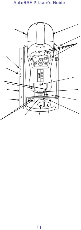
QRAE 3 Cradle
Filter
Air inlet 
Exhaust port
2 gas inlets
Sensors for testing QRAE 3
LED alarms
USB port (not shown)
DC input from AC adapter
|
Bump/Status |
Bump |
Cal |
|
|
key |
|||
2-character |
key |
|||
LED |
|
|||
LED display |
|
|
|
Capture mechanism
Release mechanism
Sensors for testing QRAE 3
LED alarms
Sensor for testing QRAE 3 buzzer
Charge contacts
Charging status LED
Cal/Status
LED
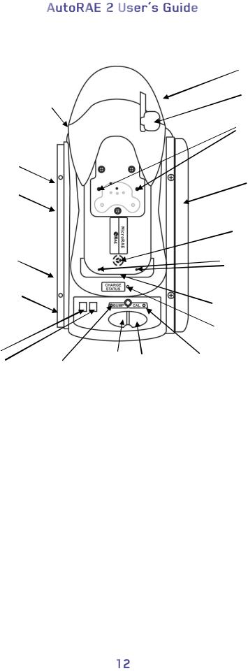
MicroRAE Cradle
Filter (hidden)
Air inlet (hidden) 
Exhaust port (not shown)
2 gas inlets (not shown)
USB port (not shown)
DC input from AC adapter
2-character |
Bump |
Cal |
LED display Bump/Status |
key |
key |
LED |
|
|
Capture mechanism
Release mechanism
Sensors for testing
LED alarms
End cap, right
Sensor for testing buzzer
Sensors for testing
LED alarms
Charge contacts (hidden)
Charging status LED
Cal/Status
LED
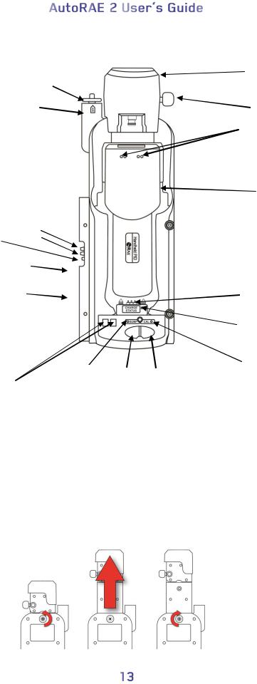
Handheld PID Cradle
|
Capture |
|
mechanism |
Filter |
|
|
Release |
Air inlet |
mechanism |
|
Sensors for testing |
|
LED alarms |
|
|
|
|
Sensor for |
|
|
|
|
|
testing |
|
|
|
|
|
buzzer |
|
2 gas inlets |
|
|
|
||
Exhaust port |
|
|
|
|
|
USB port |
|
|
|
|
|
(not shown) |
|
|
|
|
|
DC input |
|
|
|
Charge contacts |
|
from AC |
|
|
|
|
|
adapter |
|
|
|
|
|
|
|
|
|
Charging status |
|
|
|
|
|
LED |
|
|
Bump/Status |
Bump |
Cal |
Cal/Status |
|
|
key |
LED |
|||
2-character |
key |
||||
LED |
|
|
|||
LED display
Extending the Handheld PID Cradle to accommodate an UltraRAE 3000
The UltraRAE 3000 has a gas separation tube holder that extends the length of the instrument. In order to accommodate the extra length, the Handheld PID Cradle is designed so that it extends.
1.Turn the Handheld PID Cradle over.
2.Remove the screw with the red washer.
3.Pull out the capture mechanism until it is fully extended.
4.Replace the screw.
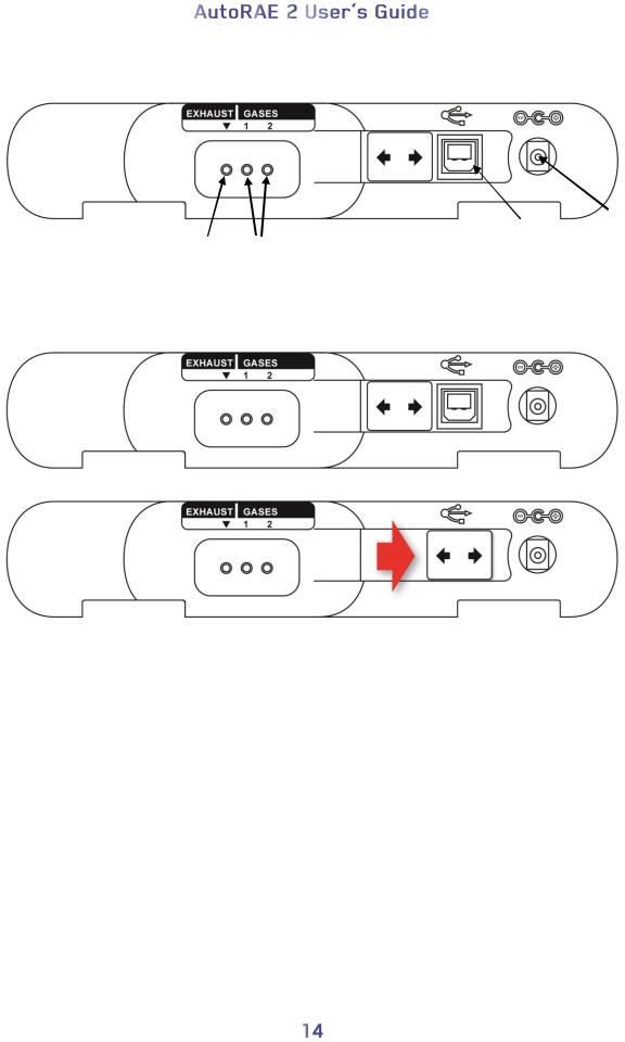
End Cap With Ports, All Models
|
|
USB |
12V DC |
|
Exhaust |
Gas |
power |
||
port |
||||
Input |
||||
port |
ports |
|||
|
||||
|
|
The USB port has a sliding cover that protects the contacts from contamination when it is not in use. Simply slide the cover over the port.

3.1. Standard Package Contents
The AutoRAE 2 Cradle for MultiRAE Pumped Monitors (P/N T02-0103-000), QRAE 3 Pumped Monitors (P/N T02-0203-000), AutoRAE 2 Handheld PID Cradle (T02-0403- 000), AutoRAE 2 Cradle for MicroRAE (P/N T02-0503-000), and AutoRAE 2 Cradle for ToxiRAE Pro Monitors (P/N T02-0003-000) are shipped with the following:
AutoRAE 2 Cradle for MultiRAE Pumped Monitors, AutoRAE 2 Cradle for QRAE 3 Pumped Monitors, AutoRAE 2 Cradle for Handheld PID (MiniRAE Lite, MiniRAE 3000, ppbRAE 3000, and UltraRAE 3000), AutoRAE 2 Cradle for MicroRAE, or AutoRAE 2 Cradle for ToxiRAE Pro Monitors
Left and right end caps (for deployment in stand-alone mode)
For ToxiRAE Pro Cradle only: Cradle comes with ToxiRAE Pro Cradle adapters and stickers for different ToxiRAE Pro models
Handheld PID Cradle only comes with 1 Quick Connector (P/N: T02-3301-000).
4 screws and 4 screw covers to attach the right end cap to the Cradle if deployed in stand-alone mode or Cradle to a controller-based system
12-volt, 1.25A power supply with interchangeable plugs, P/N 500-0114-000
External inlet filters (except Handheld PID): 1 installed, three spare (P/N 008-3022- 003, pack of 3)
Active Carbon Filter (Handheld PID only), P/N: 490-0006-000
AutoRAE 2 Handheld PID Cradle comes with 1 Quick Connector (P/N: T02-3301- 000)
Tygon tubing (1/8" I.D., 15mm long), pack of 5, P/N 411-0018-037-05
PC Communications Cable, USB Type A (Male) to Type B (Male), P/N 410-0086-000
Quick Start Guide, P/N T02-4014-000
AutoRAE 2 Resource CD-ROM, P/N T02-4012-000
This disc includes:
User’s Guide
QuickStart Guide
ProRAE Studio II Instrument Configuration and Data Management Software CDROM, P/N 000-5007-001
Product registration card
Quality inspection and test certificate
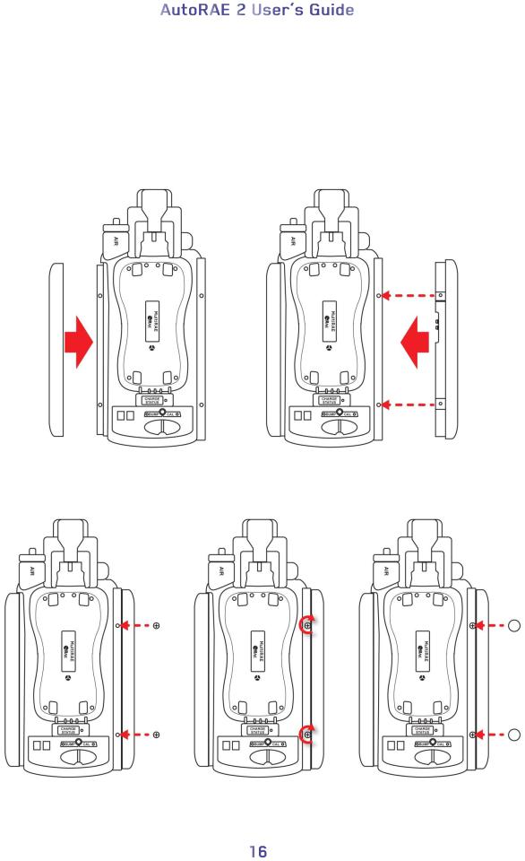
4. Installing End Caps For Stand-Alone Use
The AutoRAE 2 Cradle is shipped with left and right end caps, which are intended to protect and label the ports on both sides of the AutoRAE 2 Cradle. The one for the “input” side (left end cap) snaps on, while the one on the other side (right end cap) gets slipped into its position and is then secured with two screws (plastic caps are included, to hide the screws).
Note: The same end caps fit all cradle models.
Slide the cap over the end and snap it into place.
Slide the second cap into place.
Insert the two screws. |
Tighten the screws. |
Press the caps over the |
|
Do not overtighten! |
screws. |
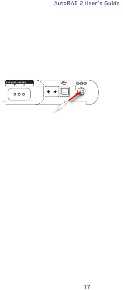
5. Powering The AutoRAE 2 Cradle
When used as a stand-alone unit, the AutoRAE 2 Cradle is powered by its own AC adapter. (When an AutoRAE 2 Cradle is attached to an AutoRAE 2 Controller, it receives its power from the AutoRAE 2 Controller, and therefore does not need a separate AC adapter.) The jack for the AC adapter connection is in the recess of the left end cap. Plug the barrel end of the AC adapter into the AutoRAE 2 Cradle and the transformer into an AC outlet.
Caution: Never use the AutoRAE 2 Cradle or its AC adapter in wet or damp environments or hazardous locations.
Plug barrel from AC adapter into jack
6. Preparing For Bump Testing & Calibration
Before performing a bump test or calibration, the AutoRAE 2 Cradle must be set up, filter installed, and power applied. In addition, it must be configured using ProRAE Studio II software to set the gas types and concentrations, as well as the time and date. See page 37 for details.
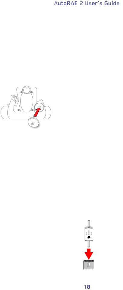
6.1. Installing An External Filter
In order to ensure that fresh air is uncontaminated by dust or other materials, use a filter on the AutoRAE 2 Cradle’s fresh air inlet. The inlet is located on the top end, to the left of the locking mechanism. Inspect the filter periodically and replace it as necessary if dirty, damaged, or contaminated.
Press filter onto receptacle
6.2. Installing An External Charcoal Filter
When zeroing the ppbRAE 3000, it is necessary to use an external charcoal filter for the truest zero readings (alternatively, you can use ultra-pure zero air). It is also a good idea to use a charcoal filter anywhere that the ambient air has VOC (volatile organic compounds). The Active Carbon Filter (P/N: 490-0006-000) filters out VOC from the air. To install the charcoal filter on the cradle, remove the plastic filter adapter by twisting the plastic filter clockwise while gently pulling outward. The Active Carbon Filter is designed for 20 uses. To help you keep track of how many calibrations are performed, there are 20 small boxes painted on the surface of the filter that you can mark with a pen after each use.
Simply press it into the receptacle on the AutoRAE 2 cradle.
Note: Make sure the arrow on the side of the filter points toward the cradle.
6.3. Connecting An AC Adapter
The AutoRAE 2 Cradle uses a 12V, 1.25A DC adapter. Plug the barrel end into the port on the side of the AutoRAE 2 Cradle and the transformer end into an AC power source. There is no power switch, so when power is applied to the AC adapter, the AutoRAE 2 Cradle is powered.
Caution: Never use the AutoRAE 2 Cradle or its AC adapter in wet or damp environments or hazardous locations.
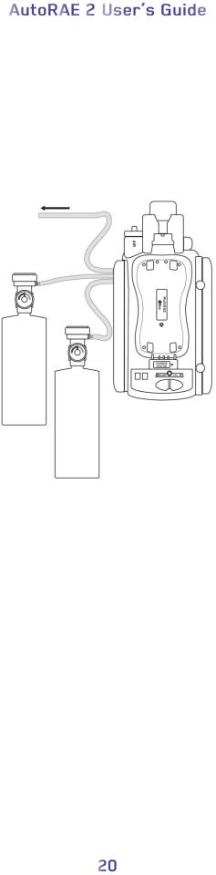
6.4. Connecting Calibration Gas
The AutoRAE 2 Cradle can accommodate two gas calibration gas cylinders (mixture or single gas in each). In addition, there is a connection labeled “Exhaust,” for venting the gas after it has gone through the AutoRAE 2 Cradle. All three connections are barbed to secure the hoses to them. All gas connections are barbed to secure the hoses to them.
Appropriately non-reactive/non-adsorptive tubing with a 1/8" I.D. should be used (Teflon for PID or corrosive or reactive gases, Tygon for others). The cylinders must have demand-flow regulators (0 to 1,000 psig/70 bar) installed.
Exhaust
Calibration gas cylinder 1
Calibration gas cylinder 2
IMPORTANT!
Always check that the active gas configuration on the AutoRAE 2 Cradle and the type/concentration of the actual calibration gases connected to the Cradle match before you begin any bump test or calibration.
Cross-Sensitivities Determine The Order In Which Sensors Should Be
Calibrated
Gases used for calibration should be configured and connected to inlet 1 and then inlet 2 in the order in which the sensors should be calibrated. This applies to both a standalone cradle and controller-based systems. Information on the order of calibration is available in RAE Systems Technical Note TN-114.
If MultiRAE sensors have cross-sensitivities to the target gas(es) of other sensors installed in the same instrument, the order in which such sensors are calibrated is important, as time is required between calibrations to allow the sensors to clear after exposure to cross-sensitive gas. To shorten the time required to perform calibration,

calibrate the most cross-sensitive sensor first, followed by the least cross-sensitive. Wait for both sensors to recover to zero, and then expose both to gas again with most cross sensitive first and least cross sensitive second.
For example, 50 ppm of NH3 produces 0 ppm response on a Cl2 (less cross-sensitive) sensor and 1 ppm of Cl2 produces about -0.5 ppm of response on a NH3 (more crosssensitive) sensor. So calibrate the NH3 sensor first with 50 ppm of NH3. This should have no effect on the Cl2 sensor. Then calibrate the Cl2 sensor with 10 ppm Cl2. This will send the NH3 sensor negative for some period of time.
After calibrating the Cl2 sensor, return the instrument to clean air and wait until the most cross-sensitive sensor (NH3) fully recovers and/or stabilizes (if it stabilizes to a number other than zero, then re-zero the instrument).
After both sensors return to zero, expose both to calibration gas in the same order (NH3 first, and then Cl2.) Note the sensor response. If both sensors are within 10% of the value shown on the gas cylinder, then the calibration of the cross-sensitive sensors was successful.
This same logic applies to the order of performing a bump test on an instrument that has cross-sensitive sensors. For more information on cross-sensitivities for select sensors, consult RAE Systems Technical Note TN-114.
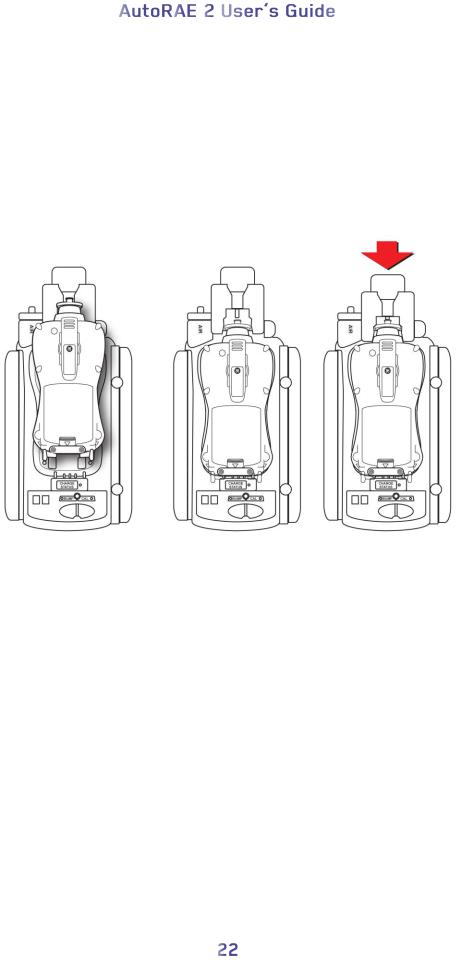
6.5.Placing A MultiRAE Monitor In The Cradle
1.Make sure the external filter on the instrument is not dirty or clogged and screwed onto the instrument inlet tightly.
2.Make sure the monitor is either turned off or is in AutoRAE 2 Communications Mode.
3.Place the instrument into the cradle face-down, making sure that it is aligned correctly with the contacts on the AutoRAE 2 Cradle’s charging port. There are two alignment points on one side and one alignment point on the other side, designed to mate with matching points on the bottom of the MultiRAE.
4.Press in on the capture mechanism to lock the MultiRAE in place.
Note: there is no need to remove the external filter, rubber boot, belt clip or wrist strap from the monitor to use it with the AutoRAE 2.
6.6. Placing A ToxiRAE Pro Monitor In The Cradle
The ToxiRAE Pro cradle requires one of two different adapters, and each is specific to the type of ToxiRAE Pro. They click into place and can be easily removed, in case you want to use one cradle for bump testing/calibrating/managing different types of ToxiRAE Pro monitors.
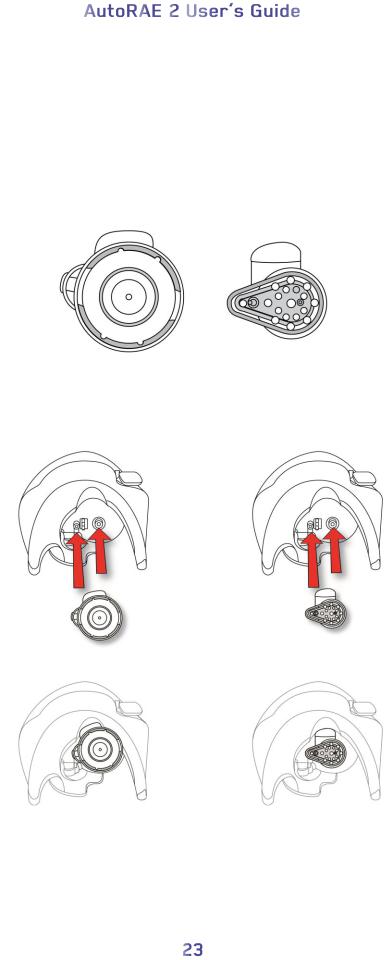
6.6.1. Installing Adapters In The ToxiRAE Pro Cradle
The two types of ToxiRAE Pro adapters are shown here:
Adapter for ToxiRAE Pro, |
Adapter for |
|
ToxiRAE Pro CO2 and |
||
ToxiRAE Pro PID |
||
ToxiRAE Pro LEL |
||
|
Align the two holes in the appropriate adapter with the two matching ports inside the Capture Mechanism.
Adapter for ToxiRAE Pro, |
Adapter for |
ToxiRAE Pro CO2 and |
ToxiRAE Pro PID |
ToxiRAE Pro LEL |
|
Note: The adapters can be removed by pulling on the “thumb tab” at the top of each one
(it fits into a niche in the capture mechanism).
Each adapter comes with a sticker for the inside of the cradle. It is especially recommended that you install these stickers, particularly if both types of adapters are being used in multiple cradles connected to an AutoRAE 2 Controller.
Place self-adhesive sticker here
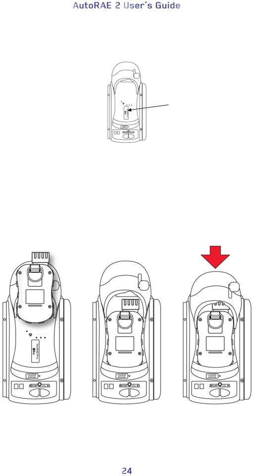
6.6.2. Placing A ToxiRAE Pro Monitor In The Cradle
1.Make sure the correct adapter is located in the cradle’s capture mechanism.
2.Make sure the external filter on the instrument is not dirty or clogged and screwed onto the instrument inlet tightly.
3.Make sure the monitor is either turned off or is in AutoRAE 2 Communications Mode.
4.Place the instrument into the cradle face-down, making check that it is aligned correctly with the contacts on the AutoRAE 2 Cradle’s charging port.
5.Press in on the capture mechanism to lock the ToxiRAE Pro in place.
Note: There is no need to remove the external filter, rubber boot, belt clip or wrist strap from the monitor to use it with the AutoRAE 2.
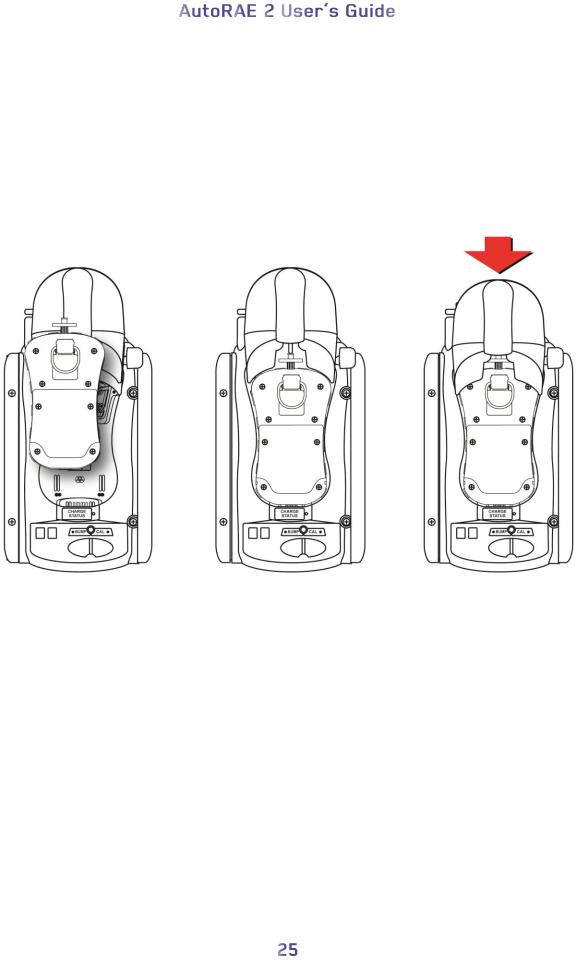
6.7. Placing A QRAE 3 Monitor In The Cradle
1.Make sure the external filter on the instrument is not dirty or clogged and screwed onto the instrument inlet tightly.
2.Make sure the monitor is either turned off or is in AutoRAE 2 Communications Mode.
3.Place the instrument into the cradle face-down, making sure that it is aligned correctly with the contacts on the AutoRAE 2 Cradle’s charging port. There are two alignment points on one side and one alignment point on the other side, designed to mate with matching points on the bottom of the QRAE 3.
4.Press in on the capture mechanism to lock the QRAE 3 in place.
Note: There is no need to remove the external filter, belt clip or wrist strap from the monitor to use it with the AutoRAE 2.
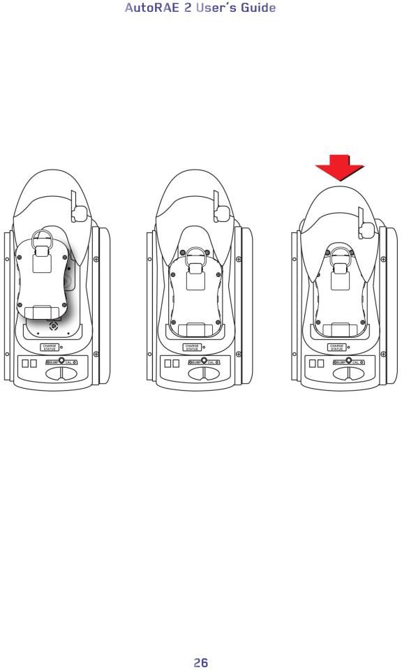
6.8. Placing A MicroRAE Monitor In The Cradle
1.Remove the external filter from the instrument.
2.Make sure the monitor is either turned off or is in AutoRAE 2 Communications Mode.
3.Place the instrument into the cradle face-down, making sure that it is aligned correctly with the contacts on the AutoRAE 2 Cradle’s charging port. There are two alignment points on one side and one alignment point on the other side, designed to mate with matching points on the bottom of the MicroRAE.
4.Press in on the capture mechanism to lock the MicroRAE in place.
Note: There is no need to remove the belt clip or wrist strap from the monitor to use it with the AutoRAE 2.
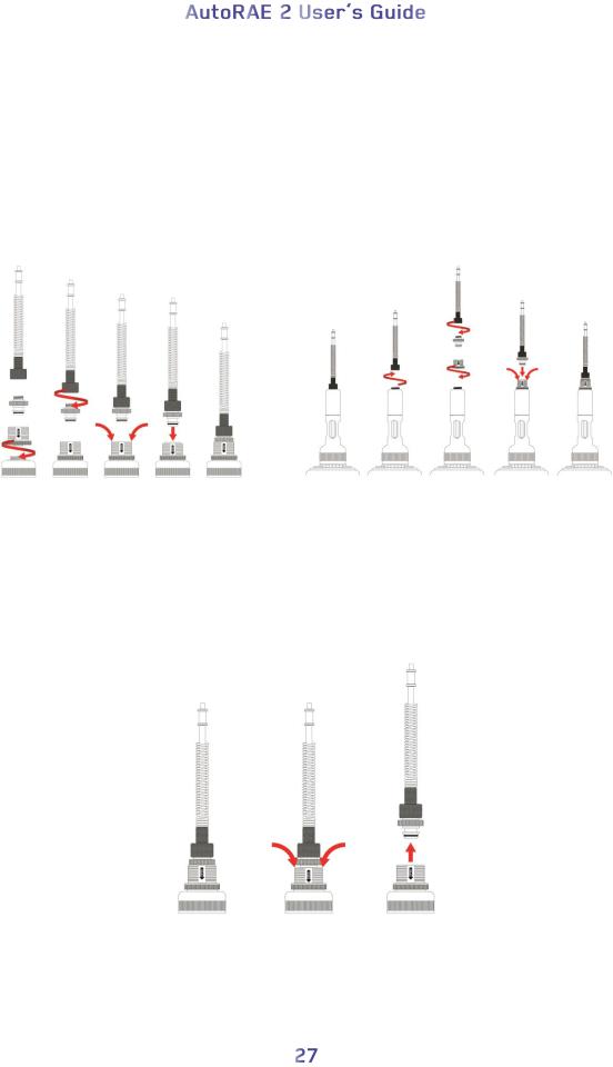
6.9. Placing A Handheld PID Monitor In The Cradle
You must remove the inlet probe before placing a handheld PID instrument (MiniRAE Lite, MiniRAE 3000, ppbRAE 3000, or UltraRAE 3000) into the cradle. If the instrument does not have a Quick Connector (P/N: T02-3301-000) already installed, you must install one.
6.9.1. Installing A Quick Connector
MiniRAE Lite, MiniRAE 3000, |
UltraRAE 3000: |
or ppbRAE 3000: |
|
To remove the inlet:
1.Press down on the collar of the Quick Connector base.
2.Lift the inlet probe off of the base.
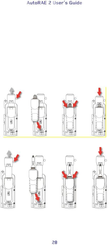
6.9.2. Installing The Instrument In the Cradle
If the instrument is equipped with a Quick Connector, install the instrument in the cradle:
1.Remove the inlet probe by pressing down on both sides of the base and releasing the probe.
2.Make sure the monitor is either turned off or is in AutoRAE 2 Communications Mode.
3.Place the instrument into the cradle face-down, making sure that it is aligned correctly with the contacts on the AutoRAE 2 Cradle’s charging port. There are two alignment points on one side and one alignment point on the other side, designed to mate with matching points on the bottom of the instrument.
4.Press in on the capture mechanism to lock the instrument in place.
For MiniRAE Lite, MiniRAE 3000, or ppbRAE 3000:
For UltraRAE 3000:
 Loading...