

Page 1
M - 12C
Detector Card Rack
®
Card rack designed to hold a power
supply and ten (10) two or four
channel, single width (1.12” wide)
detectors or twelve (12) two or four
channel, single width detectors
Reno A&E Model MH wiring harnesses
simplify installation
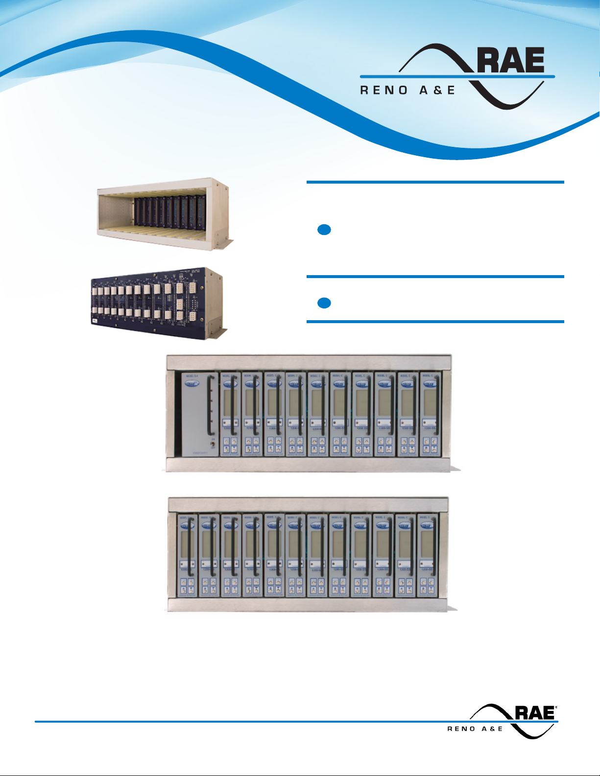
Reno A&E M-12C Detector Card Rack with a Q-4 Power Supply and Ten C-1200 Two Channel Detectors
Reno A&E M-12C Detector Card Rack with Twelve C-1200 Two Channel Detectors
The M-12C detector card rack has been designed for NEMA TS 1 applications where a shelf mounted detector
rack is needed. This rack is capable of housing a power supply and ten single width (1.12 inch), two or four
channel detectors. The M-12C may be congured to accept, in place of the power supply, two additional single
width detectors.
3510 E. ATLANTA AVENUE, PHOENIX AZ 85040 +1.480.968.6407 EDITRAFFIC.COM
Page 2
M - 12C Specications
This is a Performance Specication. It is not intended to be used as Operating
Instructions.
General Description: The Model M-12C detector card rack is designed to hold a Reno
A&E Model Q-4 power supply and ten (10) Reno A&E single width, two or four channel
detectors or twelve (12) Reno A&E single width, two or four channel detectors. Reno
A&E MH series wiring harnesses are available to simplify connections between the
M-12C and other components in the cabinet.
Card Rack Connectors (Power Supply and Detectors): PC board mounted 2 x 22
contact edge card connectors with 0.156 inch (0.396 cm.) contact centers. Connector
pin assignments are per NEMA TS1.
Back Plane Connector (Power Supply Input): 10 pin, dual row, female header, 0.165
inch (0.420 cm.) pitch with gold plated contacts. (Molex p/n 39-31-0108 or equivalent).
Mates with Molex p/n 39-01-2105 or equivalent. (See Pin Assignments - Power Supply
Inputs table.)
Back Plane Connectors (Detector Inputs and Outputs): 10 pin / 8 pin, dual row,
female header, 0.165 inch (0.420 cm.) pitch with gold plated contacts (Molex p/n 3931-0108 / 39-31-0088 or equivalent). Mates with Molex p/n 39-01-2105 / 39-01-2085 or
equivalent. (See Pin Assignments - Detector Inputs and Outputs tables.)
Back Plane Connector (Communications): 10 pin, dual row, female header, 0.165 inch
(0.420 cm.) pitch with gold plated contacts (Molex p/n 39-31-0108 or equivalent). Mates
with Molex p/n 39-01-2105 or equivalent. (See Pin Assignments - Communications
table.)
Ruggedized Construction: The M-12C housing is fabricated from 0.062 inch thick
aluminum. The printed circuit board is 0.062 inch thick FR4 material with 2 oz. copper
on both sides and plated through holes. Circuit board components are conformal coated
with polyurethane.
Operating Temperature: -40º F to +180º F (-40º C to +82º C).
Weight: 4.38 lb (1.987 kg).
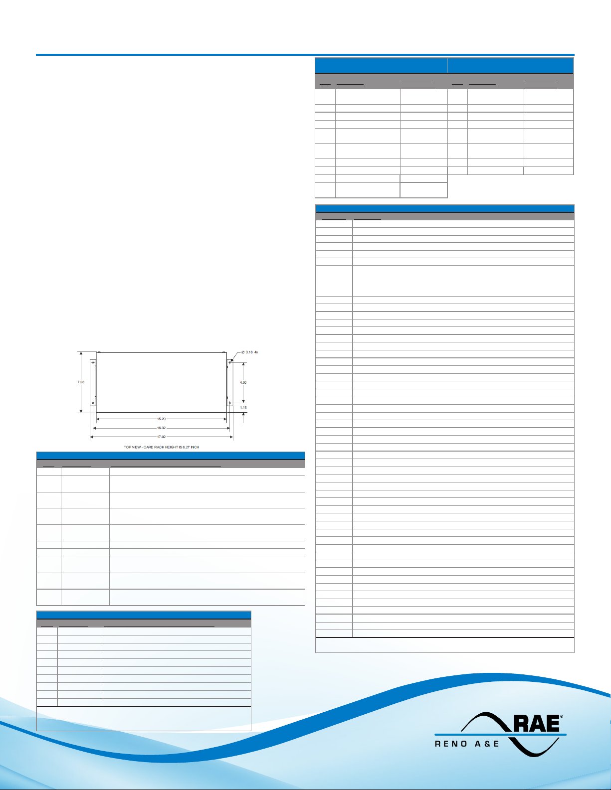
Size: 6.27 inches (15.93 cm) high x 15.20 inches (38.61 cm) wide x 7.58 inches (19.25
cm) deep (excluding mounting anges). Mounting anges add 1.50 inches (3.81 cm.) to
the width measurement.
PIN Function Edge Card Connector Termination
1 Earth Ground Pin L - Slots 1 - 12
2 Bussed Reset Pin C - Slots 1-12 (optionally congured on a per slot basis
3 DC + 3 Pins 17 & U - Slot 2 (optionally congured for internal power
4 DC + 4 Pins 18 & V - Slot 2 (optionally congured for internal power
5 DC Common Pin A - Slots 1-12 (optionally connected on a per slot basis
6 AC Neutral Pin M - Slots 1 - 12
7 AC Line Pin N - Slots 1 - 12
8 DC + 1 Pins 2 & B - Slot 2 (optionally congured for internal power
9 DC + 2 Pins 3 & C - Slot 2 (optionally congured for internal power
10 DC + DC + 1, DC + 2, DC + 3, DC + 4 tied together (optionally
PIN Function Edge Card Connector Termination
1 Rx Pin 21 - Slots 10 - 12
2 Rx Pin 21 - Slots 7 - 9
3 Rx Pin 21 - Slots 4 - 6
4 Rx Pin 21 - Slots 1 - 3
5 DC Common Pin A - Slots 1 - 12
6 Tx Pin 19 - Slots 10 - 12
7 Tx Pin 19 - Slots 7 - 9
8 Tx Pin 19 - Slots 4 - 6
9 Tx Pin 19 - Slots 1 - 3
10 DC Common Pin A - Slots 1 - 12
Note: Jumpers J44 through J65 are used to bus the communication lines. When all jumpers are installed, Rx and Tx functions may
be accessed at any of the four pairs of pins.
Power Supply Inputs
using jumpers J92 - J103)
supply) and Pin B - Slot 7, 8, 12
supply) and Pin B - Slot 9, 10, 11
using jumpers J67-J78)
supply) and Pin B - Slot 2, 3, 4
supply) and Pin B - Slot 1, 5, 6
congured using jumpers J140 - J143)
Communications
Detector Inputs & Outputs
(Channel 1 and 2)
PIN Function
1 Phase Green Input
- Ch 2
2 Loop Input - Ch 1 Pins 5 & E 2 Loop Input - Ch 3 Pins 14 & R
3 Loop Input - Ch 2 Pins 9 & K 3 Loop Input - Ch 4 Pins 18 & V
4 Call Output - Ch 2 Pin W 4 Call Output - Ch 4 Pin Y
5 DC Common Pin A 5 Phase Green
6 Phase Green Input
- Ch 1
7 Loop Input - Ch 1 Pins 4 & D 7 Loop Input - Ch 4 Pins 17 & U
8 Loop Input - Ch 2 Pins 8 & J 8 Call Output - Ch 3 Pin S
9 Call Output - Ch 1 Pin F
10 Output Emit.
Commons
Jumper Function
J38 Installed with Power Supply in Slot 2 - Pin 1 to Pin A
J39 Installed with Power Supply in Slot 2 - Pin 2 to Pin B
J40 Installed with Power Supply in Slot 2 - Pin C as DC + 2
J41 Installed with Power Supply in Slot 2 - Pin 3 to Pin C
J42 Installed with Power Supply in Slot 2 - Pins 17&U as DC + 3
J43 Installed with Power Supply in Slot 2 - Pins 18&V as DC + 4
J44-J65 Jumpers J44 through J65 are used to bus the communication lines. Even
J57-J78 Slots 1-12 DC Common (Pin A) to DC Common Bus (J25 Pin 5)
J79-J90 Slots 1-12 Output Commons (Pins H, T, X, & Z) - Output Commons Bus *
J92-J103 Slots 1 through 12 Reset (Pin C) to External Reset Bus (J25 Pin 2)
numbered jumpers bus the Tx functions on Pin 19 of each slot to the next
slot. Odd numbered jumpers bus the Rx functions on Pin 21 of each slot to
the next slot.
J91 DC Common Bus (J25 Pin 5) to Output Commons Bus *
J104 Slot 1-Ch 1 Phase Green Input (Pin 1) - Ch 2 Phase Green Input (Pin 2)
J105 Slot 1-Ch 3 Phase Green Input (Pin 3) - Ch 4 Phase Green Input (Pin 10)
J106 Slot 1-Ch 2 Phase Green Input (Pin 2) - Ch 3 Phase Green Input (Pin 3)
J107 Slot 1-Ch 1 Phase Green Input (Pin 1) - Ch 2 Phase Green Input (Pin 2)
J108 Slot 2-Ch 3 Phase Green Input (Pin 3) - Ch 4 Phase Green Input (Pin 10)
J109 Slot 2-Ch 2 Phase Green Input (Pin 2) - Ch 3 Phase Green Input (Pin 3)
J110 Slot 2-Ch 1 Phase Green Input (Pin 1) - Ch 2 Phase Green Input (Pin 2)
J111 Slot 3-Ch 3 Phase Green Input (Pin 3) - Ch 4 Phase Green Input (Pin 10)
J112 Slot 3-Ch 2 Phase Green Input (Pin 2) - Ch 3 Phase Green Input (Pin 3)
J113 Slot 3-Ch 1 Phase Green Input (Pin 1) - Ch 2 Phase Green Input (Pin 2)
J114 Slot 4-Ch 3 Phase Green Input (Pin 3) - Ch 4 Phase Green Input (Pin 10)
J115 Slot 4-Ch 2 Phase Green Input (Pin 2) - Ch 3 Phase Green Input (Pin 3)
J116 Slot 4-Ch 1 Phase Green Input (Pin 1) - Ch 2 Phase Green Input (Pin 2)
J117 Slot 5-Ch 3 Phase Green Input (Pin 3) - Ch 4 Phase Green Input (Pin 10)
J118 Slot 5-Ch 2 Phase Green Input (Pin 2) - Ch 3 Phase Green Input (Pin 3)
J119 Slot 5-Ch 1 Phase Green Input (Pin 1) - Ch 2 Phase Green Input (Pin 2)
J120 Slot 6-Ch 3 Phase Green Input (Pin 3) - Ch 4 Phase Green Input (Pin 10)
J121 Slot 6-Ch 2 Phase Green Input (Pin 2) - Ch 3 Phase Green Input (Pin 3)
J122 Slot 6-Ch 1 Phase Green Input (Pin 1) - Ch 2 Phase Green Input (Pin 2)
J123 Slot 7-Ch 3 Phase Green Input (Pin 3) - Ch 4 Phase Green Input (Pin 10)
J124 Slot 7-Ch 2 Phase Green Input (Pin 2) - Ch 3 Phase Green Input (Pin 3)
J125 Slot 7-Ch 1 Phase Green Input (Pin 1) - Ch 2 Phase Green Input (Pin 2)
J126 Slot 8-Ch 3 Phase Green Input (Pin 3) - Ch 4 Phase Green Input (Pin 10)
J127 Slot 8-Ch 2 Phase Green Input (Pin 2) - Ch 3 Phase Green Input (Pin 3)
J128 Slot 8-Ch 1 Phase Green Input (Pin 1) - Ch 2 Phase Green Input (Pin 2)
J129 Slot 9-Ch 3 Phase Green Input (Pin 3) - Ch 4 Phase Green Input (Pin 10)
J130 Slot 9-Ch 2 Phase Green Input (Pin 2) - Ch 3 Phase Green Input (Pin 3)
J131 Slot 9-Ch 1 Phase Green Input (Pin 1) - Ch 2 Phase Green Input (Pin 2)
J132 Slot 10-Ch 3 Phase Green Input (Pin 3) - Ch 4 Phase Green Input (Pin 10)
J133 Slot 10-Ch 2 Phase Green Input (Pin 2) - Ch 3 Phase Green Input (Pin 3)
J134 Slot 10-Ch 1 Phase Green Input (Pin 1) - Ch 2 Phase Green Input (Pin 2)
J135 Slot 11-Ch 3 Phase Green Input (Pin 3) - Ch 4 Phase Green Input (Pin 10)
J136 Slot 11-Ch 2 Phase Green Input (Pin 2) - Ch 3 Phase Green Input (Pin 3)
J137 Slot 11-Ch 1 Phase Green Input (Pin 1) - Ch 2 Phase Green Input (Pin 2)
J138 Slot 12-Ch 3 Phase Green Input (Pin 3) - Ch 4 Phase Green Input (Pin 10)
J139 Slot 12-Ch 2 Phase Green Input (Pin 2) - Ch 3 Phase Green Input (Pin 3)
J140 Connect DC + 1 to J25 Pin 10
J141 Connect DC + 2 to J25 Pin 10
J142 Connect DC + 3 to J25 Pin 10
J143 Connect DC + 4 to J25 Pin 10
Note: The Output Commons bus is accessible on Pin 10 of one or more of the
connectors at J13 through J24 when the jumpers for those slots are installed.
Edge Card
Connector Connector
Pin 2 1 Phase Green
Pin 1 6 Loop Input - Ch 3 Pins 13 & P
Pins H, T, X,
& Z
Jumpers
Detector Inputs & Outputs
(Channel 3 and 4)
PIN Function
Input - Ch 4
Input - Ch 3
Edge Card
Pin 10
Pin 3
M - 12C (551-1305-00) 03/23/2020
© COPYRIGHT 2020. Eberle Design, Inc. All Rights Reserved.
 Loading...