

Page 1
L - 1200 Series
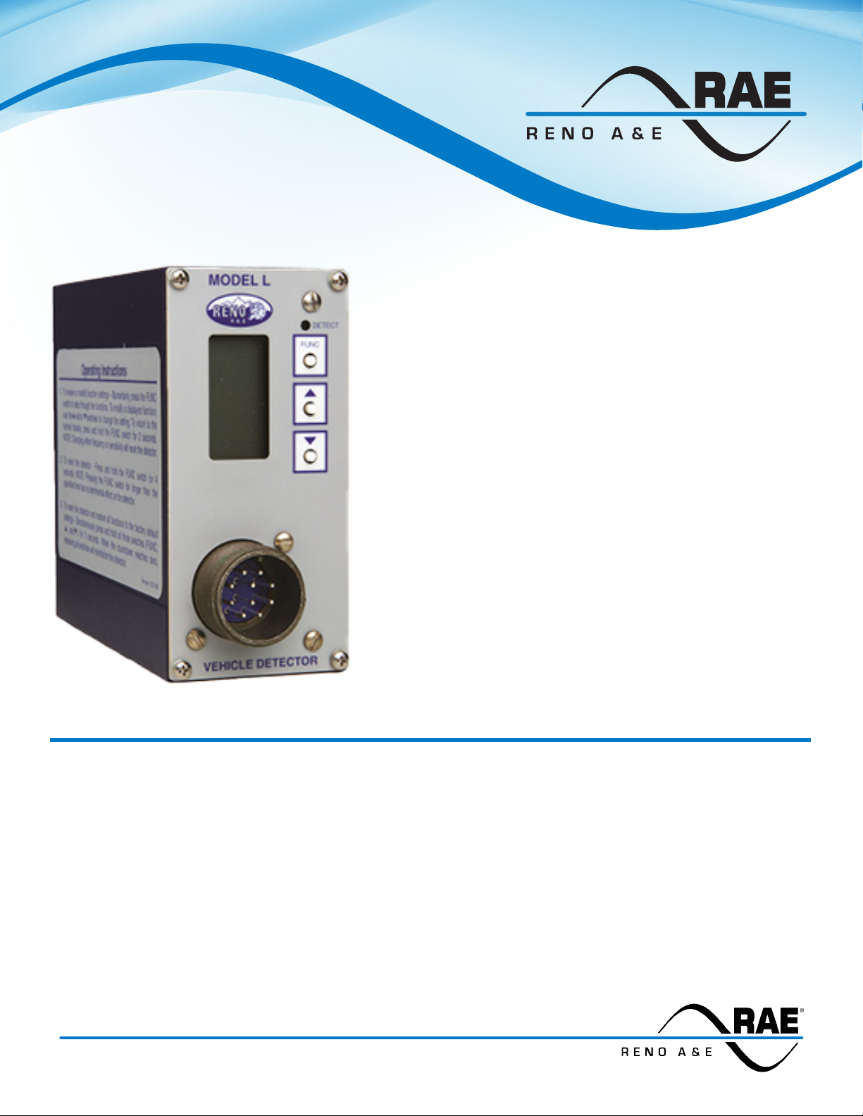
Single Channel Shelf Mount Detector
• Back-lit LCD screen displays complete detector status and
function settings:
• Eliminates guess work and provides critical information
• Provides accurate, direct visual feedback of channel
• Allows easy access to built-in detector diagnostic
• TrueCount versions provide 97% to 99% count accuracy
when used with either a single long loop or multiple 6’ x 6’
®
necessary for proper detector setup.
frequency and sensitivity settings.
features.
loops connected together.
• Audible detect signal (buzzer) facilitates loop and / or
detector troubleshooting.
• Upgrades or addition of user specic options are easily
accomplished by changing the socket mounted processor.
• Push button programming ensures long term reliability by
eliminating switch contacts.
• All programmed detector parameters are stored in non-
volatile memory.
• Directional logic capability.
The Model L-1200 series consists of detectors designed to meet or exceed NEMA Standards TS 1-1989. The L
- 1200 detector is a singe channel, shelf mount type loop detector with detect and loop fail indications provided
via a high intensity red LED and an easy to read LCD screen. All detector settings and parameters are congured
using a set of three push-buttons and the LCD screen. The L-1200 offers advanced features providing builtin diagnostic capabilities all of which are viewable by means of the LCD screen. These include: 1.) real-time
loop frequency, 2.) loop inductance and -∆L/L%, 3.) a bar-graph indication of relative inductance change (which
ensures proper selection of sensitivity level), 4.) a record of accumulated loop failures, and 5.) a timer countdown
of programmed timing functions.
Page 1
3510 E. ATLANTA AVENUE, PHOENIX AZ 85040 +1.480.968.6407 EDITRAFFIC.COM
Page 2

L - 1200 Series Specications
This is a basic performance specication and is not intended to be used as operating
instructions.
GENERAL CHARACTERISTICS:
Loop Frequency: The LCD screen displays the actual loop operating frequency which
makes it easy to quickly identify and eliminate crosstalk in the most difcult to congure
intersections. There are eight (8) selectable loop frequency settings (normally in the
range of 20 to 100 kilohertz). The actual loop operating frequency is a function of the loop
/ lead-in network and the components of the loop oscillator circuit.
Sensitivity: A unique bar graph displayed on the LCD makes it easy to quickly set
sensitivity at the ideal level for any loop / lead-in network situation. There are nine (9)
selectable sensitivity levels, plus settings for Continuous-Call and Channel-Off. See
“SENSITIVITY, - ∆L/L, & RESPONSE TIME” table.
Continuous-Call: When set to the Continuous-Call state, the detector output is
continuously in the Call state regardless of the presence or absence of vehicles over
the loop. The loop oscillator is disabled when in the Continuous-Call state. This state
is indicated by “CALL” ashing on the LCD. This option is selected from the Sensitivity
menu in Program Mode and is useful for checking controller response and other
troubleshooting activities.
Channel-Off: When set to the Channel-Off state, the detector output is continuously in
the No-Call state regardless of the presence or absence of vehicles over the loop. The
loop oscillator is disabled when in the Channel-Off state. This state is indicated by “OFF”
ashing on the LCD. This option is selected from the Sensitivity menu in Program Mode
and is useful for checking controller response and other troubleshooting activities.
Call Delay: Call Delay is adjustable from 0 to 255 seconds in 1-second steps. Call Delay
time begins when a vehicle enters the loop detection zone. The remaining Call Delay
time is continuously displayed on the LCD. Whenever a Phase Green Input (call delay
override) signal (pin J of the front panel mounted connector) is active (high state), the Call
Delay function is aborted and the Call Delay time is forced to zero.
Call Extension: Call Extension is adjustable from 0 to 25.5 seconds in 0.1-second steps.
Extension time begins when the last vehicle clears the loop detection zone. The
remaining Extension time is continuously displayed on the LCD. Any vehicle entering the
loop detection zone during the Extension time returns the detector to the Detect state,
and later, when the last vehicle clears the loop detection zone, the full Extension time
starts counting down again. NOTE: See Option 3, Call Extension Control for an alternate
mode of operation for Call Extension.
Presence / Pulse: One of two mutually exclusive modes of operation can be selected
in Program Mode:
Presence Mode: Provides a minimum Call hold time of at least 4 minutes (regardless
of vehicle size) and typically 1 to 3 hours for an automobile or truck.
Pulse Mode: An output Pulse of 125 ±10 milliseconds duration is generated for each
vehicle entering the loop detection zone. Each detected vehicle is instantly tuned out
if it remains in the loop detection zone longer than 2 seconds. This enables detection
of subsequent vehicles entering the loop detection zone. After each vehicle leaves
the loop detection zone, the detector resumes full sensitivity within 0.5 seconds.
Max Presence Timer: The Max Presence timer is adjustable from 1 to 999 seconds
in 1- second steps, plus OFF. The Max Presence function is used to limit presence
time by automatically resetting the detector. If this function is enabled (on), the Max
Presence timer begins counting down when a Call is initiated and the remaining time
is continuously displayed on the LCD. If the loop becomes vacant before the Max
Presence timer reaches zero, the Call is dropped and no automatic reset occurs. If
the End-Of Green (EOG) function is not enabled (off) and the Call is still present when
the Max Presence timer reaches zero, the detector is then automatically reset. If the
EOG function is enabled (on) and the Call is still present when the Max Presence timer
reaches zero, the detector enters a Wait state. The Wait state continues until the loop
becomes vacant; or the Phase Green Input signal for the detector (pin J of the front
panel mounted connector) transitions from green to not green with the Call still present.
If the loop becomes vacant rst, the Call is dropped and no automatic reset occurs. If
the Phase Green Input transitions from green to not green while the detector is in a Wait
state, the detector is automatically reset. The phase green signal on pin J is also called
Call Delay Override.
End-Of-Green (EOG): The EOG function is used to synchronize a detector reset with
the termination of the associated phase green. The EOG function is only available when
the Max Presence function is set between 1 and 999 seconds. It is not available when
the Max Presence function is OFF. When the EOG function is enabled (on), the detector
will automatically reset at the time the phase green input signal (pin J of the front panel
mounted connector) transitions from the ON state to the OFF state if the Max Presence
Time has counted down to zero and is resting in the Wait state. The phase green signal
on pin J is also called Call Delay Override. If an out of range loop failure condition exists
and is identied (i.e. channel will not be reset at End-of Green and the channel will
remain in the failed state.
Option 1, Loop Inductance Display: When this option is enabled (on), the LCD
screen displays the total loop inductance (actual loop inductance plus actual lead-in
inductance) in microhenries for loop inductance values in the range of 20 to 2500
microhenries. NOTE: This option is automatically disabled 15 minutes after activation
or on loss of power.
Option 2, Loop Inductance -∆L/L Display: When this option is enabled (on), the
LCD screen displays the percentage of inductance change (-∆L/L value) during the
Call state. To facilitate viewing of the maximum change in the -∆L/L value while trafc
is in motion over the detection zone, the detector will hold the peak -∆L/L value for
a period of 2 seconds. NOTE: his option is automatically disabled 15 minutes after
activation or on loss of power.
Option 3, Call Extension Control: When this option is enabled (on), the detector will
extend calls for the programmed extension time only when the Phase Green Input
signal (pin J of the front panel mounted connector) is active for the detector. When
this option is off, the detector extends ALL calls for the programmed extension time.
The signal on pin J is also called Call Delay Override.
Option 4, Noise Filter Disable: When Option 4 is enabled (on), internal noise ltering
is disabled thus providing a faster response time. When this option is off, internal noise
ltering is utilized. It is recommended that this option not be activated. The factory
default setting of “Off” provides stable operation in high crosstalk environments.
NOTE: Changing the setting of this feature will reset the detector. See “SENSITIVITY,
-∆L/L, & RESPONSE TIME” table.
Option 5, Phase Green Loop Compensation: When Option 5 is enabled (on), normal
loop compensation is used until the Phase Green Input signal (pin J of the front panel
mounted connector) becomes active. Once the Phase Green Input signal is active,
concurrent with a call output, the detector desensitizes the loop by 0.05% (-∆L/L)
over a 15 second period. This desensitization “tunes out” small changes, such as
adjacent lane pickup, therefore minimizing the chance of max timing an empty lane.
A small motorcycle may also be tuned out following the start of Phase Green. This
option is useful in minimizing the effects of false detection from adjacent lane pickup
when the detector must be run with a high sensitivity setting to ensure detection of
motorcycles. When Option 5 is not enabled (off), normal loop compensation is used.
Option 6.0, Vehicle Counting Display (TrueCount Models - See “Model Numbers”
Table): When Option 6.0 is enabled (on), the normal operating display is replaced
with the accumulated vehicle count display. The unit is capable of accumulating
65,535 counts before rolling over to 0. The LCD display will show just the hundreds,
tens, and ones digits until the accumulated count exceeds 999. At this point the
LCD display will alternate between the ten thousands and thousands digits and the
remaining three digits for hundreds, tens, and ones.
Option 6.1, Counter Reset: This setting is used to reset the accumulated count
for the detector. When Option 6.1 is changed from the off state to the on state,
the accumulated count for the detector is reset to zero. Option 6.1 will always be
in the off state when rst viewed.
Option 7.00, Vehicle Counting Loop Conguration (TrueCount Models - See
“Model Numbers” Table): The detector’s Vehicle Counting Loop Conguration
setting can be set from 7.01 to 7.05. This setting indicates the number of loops
installed in a single lane. Option 7.01 would indicate a single 6’ x 6’ loop or a long loop
such as a 6’ x 50’ Quadrupole™. The remaining four settings indicate the number of 6’
x 6’ loops installed in a single lane of trafc. NOTE: Refer to the Model L-1200 Series
Operation Manual for complete installation and operation details.
Option 11, Audible Detect Signal: When this option is enabled (on), an audible signal
will be activated whenever the detection zone is occupied. The audible signal indicates
actual occupancy of the loop detection zone. Timing and disconnect functions have
no affect on the audible signal. This feature allows a technician to watch the detection
zone on the street and conrm correct detector operation without having to look at
the detector display as well. NOTE: This option is automatically disabled 15 minutes
after activation or on loss of power.
Page 2
Page 3

C - 1000 Series Specications
Option 12.0, Detector Disconnect: The Detector Disconnect feature requires that the
Phase Green Input for the detector be connected to the proper controller phase. When
the Phase Green Input is not active (low), the detector shall operate normally. When the
Phase Green Input is active (high), at the end of each detection, the extension timer will
start to count down. If this timer reaches zero before the next detection, the detector will
no longer output a Call until the phase green input is not active. Because the extension
timer is used as a disconnect timer while in this mode, two different disconnect types
are available:
Option 12.1 OFF: Extension timing occurs and the extension timer also serves as
the disconnect timer during phase green. This will cause the Call output to remain
in the Call state until disconnect occurs. This may allow the user to use gap times
appropriate for the advanced loops without considering the effects on the stop bar
loops.
Option 12.1 ON: Extension timing is disabled and the extension timer is used as the
disconnect timer. This will cause the Call output to follow the occupancy of the loop
detection zone until disconnect occurs.
The intent of this feature is for use in applications where a loop at the stop bar is not
needed after any waiting queue in the associated trafc lane is moving during the green.
Note: Refer to the Model L-1200 Series Operation Manual for complete installation and
operation details.
SPECIFICATIONS (PHYSICAL):
Weight: 24 oz (680 gm).
Size: 4.70 inches (11.94 cm) high x 2.25 inches (5.72 cm) wide x 5.30 inches (13.46 cm)
deep (excluding connector). Connector add .675 inch (1.71 cm) to depth measurement.
Operating Temperature: -40°F to +180°F (-40°C to +82°C).
Circuit Board: Printed circuit boards are 0.062 inch thick FR4 material with 2 oz. copper
on both sides and plated through holes. Circuit boards and components are conformal
coated with polyurethane.
Connector: MS 3102A-18-1P 10 pin male. See “PIN ASSIGNMENTS” table.
Loop Feeder Length: Up to 5000 feet (1500 m) maximum with proper feeder cable and
appropriate loops.
SPECIFICATIONS (ELECTRICAL):
Power: 89 to 135 VAC, 50/60 Hz, 4 Watts maximum.
Loop Inductance Range: 20 to 2500 microhenries with a Q factor of 5 or greater.
Loop Input: Transformer isolated. The minimum capacitance added by the detector is
0.068 microfarads.
Lightning Protection: The detector can tolerate, without damage, a 10 microfarad
capacitor charged to 2,000 volts being discharged directly into the loop input terminals,
or a 10 microfarad capacitor charged to 2,000 volts being discharged between either loop
terminal and earth ground.
Reset: Meets and/or exceeds NEMA TS 1 detector specications. The detector can
be reset by removing and reapplying power or by changing the setting of Option 4
(Noise Filter Disable). The detector can also be reset by pressing the FUNC button for 3
seconds or by changing the sensitivity or loop frequency. NOTE: Resetting the detector
by pressing the FUNC button or changing the setting of Option 4 does not disable any
selectable diagnostic functions. If any diagnostic option(s) (Option 1, Option 2, or Option
11) has (have) been activated, it (they) will remain activated following the detector reset
or change of Option 4 setting. Resetting the detector by removing and reapplying power
disables all selectable diagnostic features.
Phase Green Input: Also known as Call Delay Override. Meets and/or exceeds all NEMA
TS 1 requirements. Application of a high state voltage (89 to 135 VAC) to pin J of the front
panel mounted connector causes the delay timer to abort the delay timing function and
also provides control for Phase Green Loop Compensation, Max Presence Timing (Endof-Green), Extension Timing, and Detector Disconnect, if the features are programmed.
Solid State Output Ratings: Optically coupled eld effect transistors. 30 VDC maximum
drain to source. 50 mA maximum current. 1.2 VDC maximum transistor saturation
voltage. The output transistor is protected with a 33-volt zener diode connected between
the drain and source.
Relay Ratings: The relay contacts are rated for 6 Amps maximum, 150 VDC maximum,
and 180 Watts maximum switched power.
SPECIFICATIONS (OPERATIONAL):
Display: The LCD back-lighting illuminates whenever any push-button is pressed. The
back-lighting will extinguish 15 minutes after the last actuation of any push-button.
Detect Indicators: The detector has a super-high-intensity, red, light-emitting-diode
(LED) to indicate a Call output, Delay Timing, Extension Timing, or failed loop.
Response Time: Meets or exceeds NEMA TS 1 response time specications. See
“SENSITIVITY, -∆L/L, & RESPONSE TIME” table for actual response times.
Self-Tuning: The detector automatically tunes and is operational within 2 seconds
after application of power or after being reset. Full sensitivity and hold time require
30 seconds of operation.
Environmental & Tracking: The detector is fully self-compensating for environmental
changes and loop drift over the full temperature range and the entire loop inductance
range.
Grounded Loop Operation: The loop isolation transformer allows operation with
poor quality loops (which may include one short to ground at a single point).
Loop (Fail) Monitor: If the total inductance of the detector’s loop input network
goes out of the range specied for the detector, or rapidly changes by more than
±25%, the detector will immediately enter the Fail-Safe mode and display “LOOP
FAIL” on the LCD screen. The type of loop failure will also be displayed as “L lo”
(for -25% change or shorted loop conditions) or “L hi” (for +25% change or open
loop conditions). This will continue as long as the loop fault exists. However, if the
detector is reset, or power is momentarily lost, the detector will retune if the loop
inductance is within the acceptable range. If any type of loop failure occurs in one (or
more) loop(s) in a group of two or more loops wired in parallel, the detector will not
respond with a fail-safe output following any type of reset. It is essential that multiple
loops wired to the detector always be wired in series to ensure fail-safe operation
under all circumstances. The Fail-Safe mode generates a continuous call in Presence
Mode or in Pulse Mode. At the time of a loop failure, the LED will begin repeating a
burst of three ashes each one second. The LED will continue these bursts until the
detector is manually reset or power is removed. If the loop “self heals”, the “LOOP
FAIL” message on the LCD will extinguish and the detector will resume operation
in a normal manner; except the LED will continue the bursts thus providing an alert
that a Loop Fail condition occurred. Each loop failure for the detector is counted and
accumulated into the Loop Fail Memory. The total number of loop failures written into
the Loop Fail Memory (since the last power interruption or manual reset) is viewed
by stepping through the detector’s functions in Program Mode to the “LOOP FAIL”
message.
Full Restore To Factory Defaults: Pressing all three front panel switches
simultaneously and continuously for 5 seconds resets the detector and restores all
the factory default settings. The countdown of the 5-second period is displayed on
the LCD screen. Releasing any of the switches before the countdown ends will abort
the Full Restore operation. See “FACTORY DEFAULT SETTINGS” table.
Display Test: Pressing any two of the front panel switches simultaneously will display
all possible symbols and messages on the LCD screen.
Page 3
Page 4

L - 1200 Series Specications
Sensitivity, -∆L/L, & Response Time
Response Time
Sensitivity -∆L/L
OFF --- --- ---
1 0.64% 96 ±16 milliseconds 12 ±2 milliseconds
2 0.32% 96 ±16 milliseconds 12 ±2 milliseconds
3 0.16% 96 ±16 milliseconds 12 ±2 milliseconds
4 0.08% 96 ±16 milliseconds 12 ±2 milliseconds
5 0.04% 96 ±16 milliseconds 12 ±2 milliseconds
6* 0.02% 96 ±16 milliseconds 15 ±3 milliseconds
7 0.01% 96 ±16 milliseconds 23 ±5 milliseconds
8 0.005% 96 ±16 milliseconds 38 ±8 milliseconds
9 0.0025% 96 ±16 milliseconds 68 ±14 milliseconds
CALL --- --- ---
Function Setting
Frequency 3
Sensitivity 6
Delay Time 0
Extension Time 0
Max Presence Time OFF
Presence/Pulse Mode Presence
End-of-Green (EOG) OFF
Option 1 - Loop Inductance Display OFF
Option 2 - Loop Inductance -∆L/L Display OFF
Option 3 - Call Extension Control OFF
Option 4 - Noise Filter Disable OFF
Option 5 - Phase Green Loop Compensation OFF
Option 6.0 - Vehicle Counting Display OFF
Option 6.1 - Counter Reset OFF
Option 7 - Vehicle Counting Loop Conguration 04
Option 11 - Audible Detect Signal OFF
Option 12.0 - Detector Disconnect OFF
Option 12.1 - Detector Disconnect Type OFF
Noise Filter Enabled
(Option 4 Off)
* Denotes Factory Default
Factory Default Settings
Response Time
Noise Filter Disabled
(Option 4 On)
Pin Assignments:
PIN Function
A Power, Neutral, 120 VAC
B Output, Relay Common
C Power, Line, 120 VAC
D Loop Input
E Loop Input
F Output, Relay Normally Open
G Output, Relay Normally Closed
H Chassis Ground
I No Connection
J Phase Green Input
Model L-1200-R
Pin Assignments:
PIN Function
A Power, Neutral, 120 VAC
B Output, Source
C Power, Line, 120 VAC
D Loop Input
E Loop Input
F Output, Drain
G No Connection
H Chassis Ground
I No Connection
J Phase Green Input
Model L-1200-SS
Pin Assignments:
PIN Function
A Power, Neutral, 120 VAC
B Output, Source
C Power, Line, 120 VAC
D Loop Input
E Loop Input
F No Connection
G No Connection
H Chassis Ground
I Output, Drain
J Phase Green Input
Model L-1200-SSTX
Pin Assignments:
PIN Function
A Power, Neutral, 120 VAC
B Output, Relay Common
C Power, Line, 120 VAC
D Loop Input
E Loop Input
F Output, Relay Normally Open
G
True Count Output
H Chassis Ground
I
True Count Output
J Phase Green Input
Model L-1201-R
, Relay Normally Closed
, Relay Common
Pin Assignments:
PIN Function
A Power, Neutral, 120 VAC
B Output, Source
C Power, Line, 120 VAC
D Loop Input
E Loop Input
F Output, Drain
G
True Count Output
H Chassis Ground
I
True Count Output
J Phase Green Input
Model Description
L -1200 - R TS 1 Type, Relay Outputs
L - 1200 - SS TS 1 Type, Solid State Outputs
L - 1200 - SSTX TS 1 Type, Solid State Outputs, TX DOT Specication
L - 1201 - R TS 1 Type, Relay Outputs with
L - 1201 - SS TS 1 Type, Solid State Outputs with
Model L-1201-SS
, Drain
, Source
Model Numbers
TrueCount Outputs
True Count Outputs
Distributed By:
Page 4
Model L-1200 (P/N 551-1204-00) 3/31/2020
© COPYRIGHT 2020. Eberle Design, Inc. All Rights Reserved.
 Loading...