

Page 1

046-4001-000, Revision C, June 2005
Page 2

b
This manual must be carefully read by all individuals who have
or will have the responsibility of using, maintaining, or servicing
this product. The product will perform as designed only if
manufacturer’s instructions.
Caution!
To reduce the risk of electric shock, turn off power before removing the
monitor cover. Disconnect the battery before removing sensor modules for
service. Never operate this monitor while the cover is removed. Remove
monitor cover and sensor modules only in an area known to be non-
hazardous.
Special Note
When the EntryRAE monitor is removed from the transport case and is
turned on for the first time, there may be residual vapors trapped inside the
monitor, and the initial toxic gas sensors values may indicate a few ppm.
After running the monitor for several minutes in clean air, the residual vapors
should clear and readings should return to near zero.
Attention! For European Applications
A. Recharge batteries in non-hazardous locations.
C. Use RAE Systems Charging cradle (P/N 046-3059-000) for connection to
communication port and charging jack only in a non hazardous area.
Only the combustible gas detection portion of this instrument has been
assessed for performance in accordance with C22.2 No.152-M1984.
Seulement la partie combustible de détection de gaz de cet instrument a été
evaluée pour l’exécution selon C22.2 No. 152-M1984.
5,393,979 , 5,561,344 , 5,773,833 , 6,225,633 ,
6,313,638 , 6,333,632 , 6,320,388
WARNING
To prevent ignition of flammable or combustible atmospheres, disconnect
power before servicing.
WARNING
manufacturers.
WARNING
Substitution of components may impair intrinsic safety.
!
!
!
!
!
!
!
Page 3

c
Warnings
serviced by qualified personnel only. Read and understand the
instrument has not been tested in an explosive gas/air atmosphere having an
oxygen concentration greater than 21%. Substitution of components may impair
intrinsic safety. Recharge/replace batteries only in non-hazardous atmospheres.
Computer Interface
atmospheres.
Static Hazard
Clean only with a damp cloth.
Calibration
While the EntryRAE has been factory calibrated prior to shipment, transport
and storage after leaving the factory can affect the sensors. Therefore, any
newly purchased RAE Systems Instrument should be fully calibrated by
exposing it to known concentration calibration gases before the instrument
is put into service for the first time. For safety, check the accuracy of the
monitor by exposing the sensors to calibration gas(es) before each day’s
use. (Refer to “Calibration” on page 10.)
Caution!
concentration of methane gas equivalent to 20% to 50% of full-scale
concentration. Accuracy must be within 0% to +20% of actual. Accuracy may
be corrected by calibration. Refer to “Calibration” on page 10.)
use after long storage requires installation of the batteries and a warm-up
period of at least 10 minutes for the sensors to equilibrate. The user should
recognize that sensor life is based upon the purchase date.
Any rapid up-scale reading followed by a declining or erratic reading may indicate
a gas concentration beyond the upper scale limit, which may be hazardous.
CAUTION:
HIGH OFF-SCALE READINGS MAY INDICATE AN EXPLOSIVE
CONCENTRATION!
!
!
!
!
!
!
!
!
!
Page 4

d
Avertissements
entretenu et réparé uniquement par un personnel qualifié.
d’entretenir ou de réparer l’équipement.
046-3007-000 ou 046-3051-000). Cet instrument n’a pas été essayé dans une
atmosphère de gaz/air explosive ayant une concentration d’oxygène plus élevée
que 21%. La substitution de composants peut compromettre la sécurité intrinsèque.
Câble de Computer
Connecter pas le câble externe que dans environnements non dangereux.
exposant l’instrument à une concentration de gaz connue par une procédure
diétalonnage avant de mettre en service l’instrument pour la première fois.
exposant l’instrument. (Référez la Calibration à la page 10.)
Attention!
Avant chaque utilisation journalière verifier la sensibilité avec une concentration
connue de methane equivalante a 20% à 50% de la pleine échelle. La precision
doit être comprise entre 0% à +20% de la valeur vraie et peut être corrigée par
une procédure diétalonnage. (Référez la Calibration à la page 10.)
Stockage à Long Term
utilisation régulière de celui ci. Lors d’un stockage à long terme, la batterie
doit être déconnectée. Le rédémarrage aprés une longue période d’arrêt,
nécessite la réinstallation de la batterie, et une période de chauffage de 10 mn
afin que les capteurs se mettent à l’équilibre. L’utilisateur doit être conscient
que la durée de vie indiquée pour le capteur démarre à sa date d’achat.
Toute lecture rapide et positive, suivie d’une baisse subite au erratique de la
valeur, peut indiquer une concentration de gaz hors gamme de détection qui
peut être dangereuse.
ATTENTION:
DES LECTURES SUPÉRIEURES A L’ÉCHELLE PEUVENT
!
!
!
!
!
!
!
!
Page 5

e
Warnings
c
Avertissements
d
General Information
2
4
5
Operating the EntryRAE
6
Turning the Monitor On
6
Warm-up Sequence
6
Turning the Monitor Off
7
8
The Pump Cycle
8
Continuous Operation of the Pump
88Calibration
Calibration Equipment
Calibration Procedure
Optional Step: Zero Calibration for the Oxygen Sensor
4
Calibration Period
5
6
Alarm Signals
7
Testing Alarm Signals
7
Alarm Conditions
888
Sampling Pump
9
9
Charging the EntryRAE
9
Table of Contents
Page 6

f
T2121
Security
21
22
23
Change Monitor Setup
2327272
9
Sensor Replacement
30
CO Sensor Charcoal Filter
32
Cleaning the PID
33
Setting Pump Stall Threshold
34
Specifications
35 Certifications
36
Sensor Range and Resolution
3
6
Service and Repair Record
3
7
SPECIAL NOTE:
The
where the monitor was purchased; they will
return the monitor on your behalf,
or
The
monitor for service or repair, obtain a Returned Material Authorization (RMA)
number for proper tracking of your equipment. This number needs to be on
all documentation and posted on the outside of the box in which the monitor
is returned for service or upgrade.
Packages without RMA Numbers will be
refused at the factory.
Page 7

1
The EntryRAE is a 4-gas plus PID (photoionization detector) gas moni-
available today.
Also includes CO, H
2
S, LEL and O
2
sensors
Visual alarm with bright red flashing LEDs
tor. Reliable, easy to operate and simple to calibrate, the EntryRAE
delivers added protection without added complexity.
Simple, Modular, Durable PID
Page 8

2
Photo Item
Number
Part Name
Part Number
Monitor Only
*Shipping case
Monitor
701-3040-000
Sensors
Photoionization Detector
023-0102-000
Oxygen (O
)
046-1161-000
Combustible (%LEL, %Vol)
014-0212-000
Carbon Monoxide (CO)
032-0200-000
2
S)
032-0202-000
Rechargeable Li-Ion Battery
046-3007-000
3
Charging Cradle
- 120 V AC to 12 V DC wall charger, US plug or
- 230 V AC to 12 V DC wall charger, Euro plug
046-3059-000
500-0036-000
500-0036-001
4
Alkaline Battery Adapter
046-3051-000
5
Calibration Adapter/Tubing Assembly
046-3040-000
7
External Filters (5-pack)
046-3022-005
Charcoal Filters (for the CO Sensor)
008-3006-005
8
User Manual
046-4001-000
EntryRAE Resource CD
046-4013-000
Computer Interface Cable - RS232 to RS232 with USB
adapter
002-3009-000
9
Remote Sampling Probe with 15 feet (5 meters) of
self-coiling Teflon (tm) tubing
008-3015-002
5
Tool Kit
081-0005-000
O
S, 50 ppm CO)
600-0050-004
600-0002-000
6
Regulator (male) with tubing
007-3021-000
6
Regulator (female) with tubing
002-3011-000
4-year repair and replacement guarantee
SVC-PTC4-046
not shown
AutoRAE Docking Station Starter Kit
048-5900-000
not shown
Additional AutoRAE Cradle
048-0154-000
not shown
PID Cleaning Kit
500-0014-010
* Different shipping cases are used for monitor-only and calibration kits.
Optional Confined Space Kit II (CSK II) 046-0911-000
Optional Guaranteed Cost of Ownership
Optional Accessories (items sold separately)
Page 9

3
8
5
5, 6
9
3
Page 10
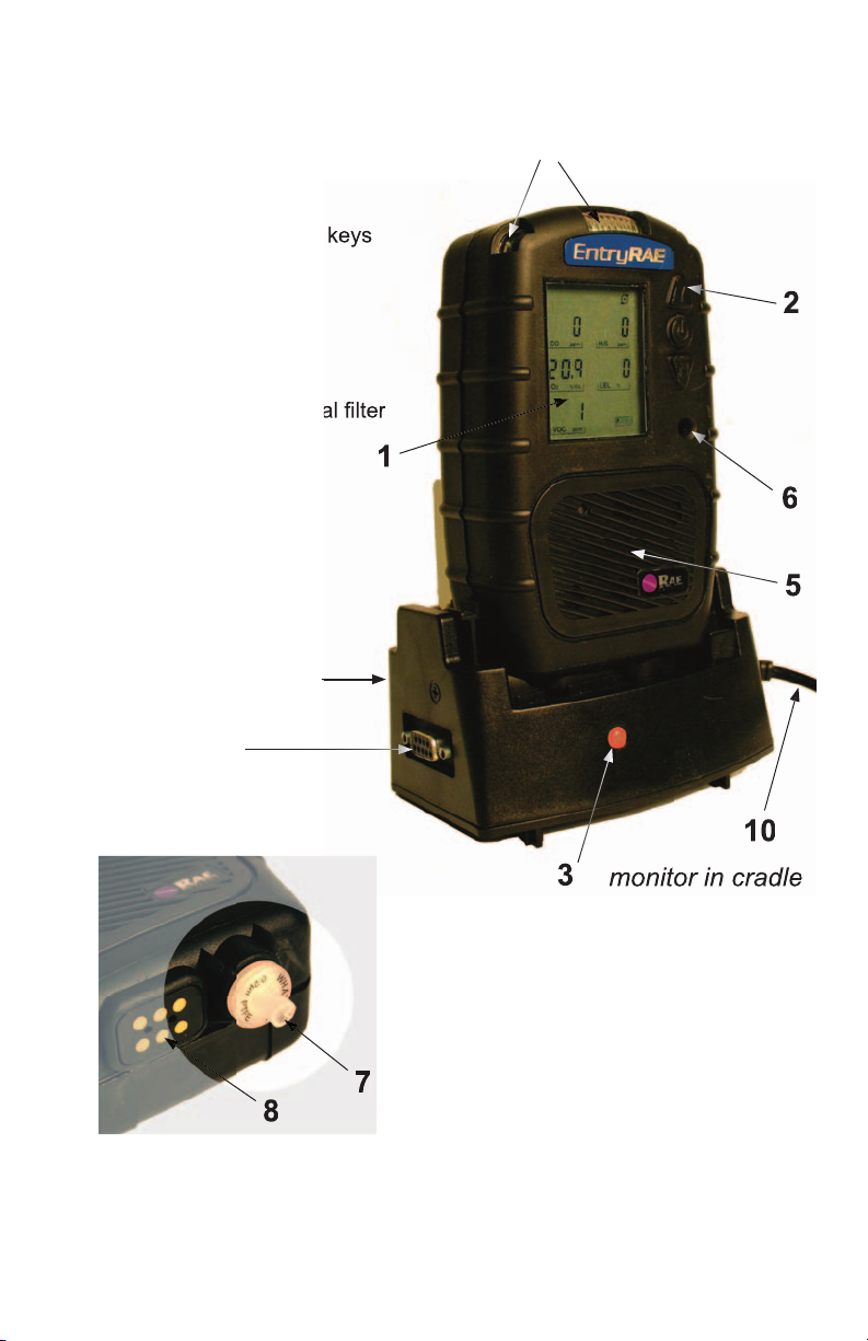
4
2. Operation / Program keys
3. Charge status
4. Visual alarm
5. Gas plate
6. Buzzer
7. Gas inlet with external filter
8. Charging contacts
9. Charging cradle
9
5
6
8
3
bottom of monitor
monitor in cradle
Page 11

5
2. Alarm conditions (
page 18
)
3. Pump on (
page 19
)
4. Pump off
5. Time (
page 25
)
6. Date (Day, Month, Year)
7. Apply calibration gas (
page 12
)
8. Battery charge status (
page 19
)
9. Password protected (
page 11, 26
)
HIGHLOW TWA STEL
D1
D2
D3
D4
D5
D6
D7
D8
D9
D10
D11
D12
D13
D14
D15
D16
D17
A
B
C
D
E
F
G
ALARM
H S
2 ppm
CO ppm
VOC
ppm
LEL %VOL
O
2 %VOL
.
D M Y
:
HIGHLOW TWA STEL
HIGHLOW TWA STEL
HIGHLOW HIGHLOW
.
?
S
PAN
O
OVER
D8
D9
D10
D11
D12
D13
D M Y
7
5
6
3
D4
D5
D6
D7
:
9
8
Page 12

6
3.1
The time is shown in 24-hour format, and the
date is shown in “ddmmyy” format.
3.2 If the monitor has never been programmed, you
will see a “date error” message. Press @ to
acknowledge the error. (Refer to “Adjust Date?”
on page 20 to reset the time and date.)
3.0 The
Time and Date settings are checked:
The external filter must always be used with the monitor.
Turning the Monitor On
!
2.1 The EntryRAE firmware version displays.
2.2 All of the display segments appear.
2.3 The buzzer sounds twice (if the unit has not
off.
2.4 The preset alarm limits appear in order:
To turn the monitor on
2.0 The warm-up sequence begins:
4.0 PID Warm-up:
4.1 If the monitor has not been used recently, PID
warm-up of up to three minutes (180 seconds)
occurs. During this time, the PID lamp icon
appears, as well as a countdown from 180 to 1.
Page 13
7
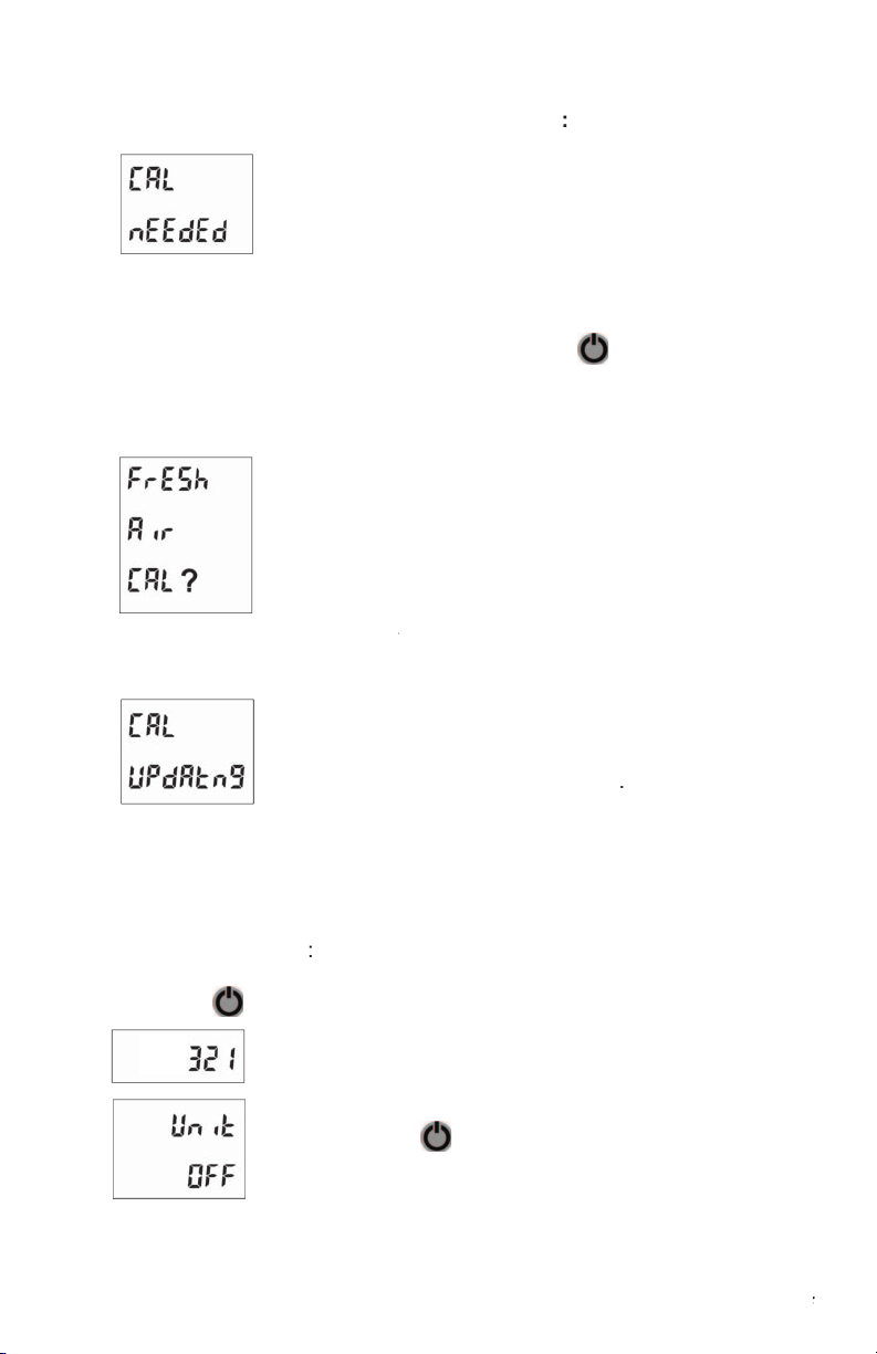
5.1
Calibration Needed
This message appears if the number of days
since the last calibration is greater than the “Cal
If the Time and Date are invalid or
were recently updated, then calibration is
automatically due. Press @ to acknowledge
the message.
6.1
6.2 The monitor must be in clean ambient air during
fresh air calibration.
6.3 Press
and the calibration begins. The display
counts down from 5 to 0 (6 seconds), at which
time the process is complete.
6.4 “Cal Updating.” The calibration data is updated,
the monitor warm-up is complete, and the
5.0 The date of the last calibration is checked
6.0 A
is requested
Press the @ button for 5 seconds.
Turning the Monitor Off
The monitor cannot be turned off until after the warm-up sequence is
completed.
To
turn the monitor off
The display counts down from 3 to 1
(3 seconds), and flashes the LED for each
count.
display.
Page 14

8
The Pump Cycle
state, the pump cycles on and off about every 8 seconds. This on/off cycle
The pump runs continuously when:
condition.
2.0 When the concentration of VOCs is nearing an alarm condition.
Continuous Operation of the Pump
Y
N
continuously for 5 minutes. This value can be changed using the ProRAE
Studio software.
CAUTION:
HIGH OFF-SCALE READINGS MAY INDICATE AN
ATTENTION:
LES LECTURES HORS ÉCHELLE ÉLEVÉES PEUVENT
Page 15

9
the current measured readings for each enabled sensor.
sensors. Press @ to scroll through these readings:
STEL
- The Short Term Exposure Limit for CO, H
S,
and VOC gases only; the average reading of the
gas concentration for the last 15 minutes, which is
updated every minute. Dashes (“- - -”) appear for the
first 15 minutes.
- The Time Weighted Average for CO, H
S, and
VOC gases only; the accumulated reading of the
gas concentration since the monitor was turned on,
divided by 8 hours. Updated every minute.
– The lowest reading for each gas
concentration since the monitor was turned on;
updated every second. Press
Y
to reset the
- The highest reading for each gas
concentration since the monitor was turned on;
updated every second. Press
Y
to reset the high
values.
LOW
LOW
LOW
LOW
Page 16

for calibration.
for 3 seconds to
enter Programming.
While EntryRAEs are calibrated prior to leaving the factory, temperature
extremes and/or shocks during shipment can cause sensor drift. Therefore,
the accuracy of any newly purchased RAE Systems monitor should be
tested by exposing the sensor(s) to known concentration calibration gas
before the monitor is used or put into service. For maximum safety, the
accuracy of the monitor should be checked by exposing the sensor(s) to
known concentration calibration gas before each day’s use.
en exposant l’instrument à une concentration de gaz connue par une
procédure dietalonnage avant metre en service l’instrument pour la
première fois. Pour une sécurité maximale, la sensibilité du EntreRAE doit
être vérifie en exposant l’instrument à une concentration de gaz connue
par une procédure diétalonnage avant chaque utilisation journaliere.
Information regarding sensor expiration is listed in Technical Note TN-
Calibration Equipment
The sensors are calibrated using both fresh air and calibration (span)
gas. The EntryRAE span gas mixtures are xed. To calibrate an
A. A cylinder of four-gas mix containing:
50% LEL methane
s
20.9% O
2
s
10 ppm H
2
S
50 ppm CO
C. A calibration adapter to connect the monitor to the outlet of the gas
cylinder.
Calibration Procedure
The calibration procedure is broken down into three steps. All steps
should be performed whenever calibration is needed.
Step One: Enter Programming Mode
!
!
Page 17

11
If a password is enabled
to increase the digit and
to
decrease the digit.
Y
to enter the password.
2.1 Press
Y
and the calibration begins. The display
counts down from 5 to 1 (5 seconds), at which
time the process is complete.
Calibration Updating
The monitor is in the process of calibrating the
sensors. As it completes, the display shows
the sensors registering zero (or 20.9% for O
),
ambient air may be contaminated with hydrocarbons. Attach the filter
to the EntryRAE during fresh air calibration. The filter can be used up
to 20 times before disposing. This filter removes most heavier organic
and inorganic compounds, but may not completely remove lighter
compounds such as methane, propane and CO. Note that the filter
should be attached to the EntryRAE before the calibration adapter.
Step Three: Span Gas Calibration for Multiple Sensors
3.0 For this calibration step, the LEL, CO and H
2
S sensors are calibrated
using the 4-gas mix (P/N 600-0050-004).
Step Two: Fresh Air Calibration
The monitor must be in clean ambient air during fresh air calibration.
Page 18

3.1 Connect the calibration adapter to the EntryRAE and put a regulator
(500 cc per minute flow rate) on the 4-gas mix cylinder.
3.2 After “Span Cal?” appears on the display with the
CO, H
S, and LEL sensors indicated, press
3.3 Turn the gas all the way on.
3.3 Connect the open end of the calibration
adapter to the regulator.
The monitor starts to
countdown from 70 seconds.
3.4
When the countdown timer reaches zero, turn
off the gas, and disconnect the calibration
adapter from the regulator.
3.5 Compare the readings displayed to the span
gas values indicated on the gas cylinder. The
values.
Page 19

13
Step Four: Span Gas Calibration for the PID Sensor
4.1 The final step is to calibrate the PID sensor.
4.2 Connect the EntryRAE calibration adapter to the monitor (see Figure
6) and put a regulator (500 cc per minute flow rate) on the cylinder of
4.3 Connect the open end of the calibration adapter to the regulator.
3.6 If calibration fails, the monitor briefly displays “Err”
above each failed sensor.
Stop calibration in the event that the
gas runs out or is disconnected. To interrupt
calibration, press @ . When calibration stops, the
sensors revert to their previous calibration values.
3.7 After briefly displaying the concentration, the
4.4 When “Span Cal?” appears on the display
with the VOC sensor indicated, press
Y
and turn the gas all the way on. The
4.5 Turn off the gas, dicsconnect from the
adapter, and remove the calibration
adapter from the monitor.
displays “Err” above the failed sensor.
Stop calibration if the gas runs out
or is disconnected. To interrupt calibration,
sensors revert to their previous calibration
values.
Page 20

Optional Step: Zero Calibration for the
Oxygen Sensor
Zero calibration for the oxygen sensor is not required
under normal use. A span calibration using ambient
air (20.9% O
) is usually sufficient to establish its
for special applications. Zero gas (100% nitrogen) is
ordered separately (P/N 600-0062-000).
Zeroing the O
Sensor
Connect the calibration adapter to the EntryRAE and
cylinder of nitrogen.
Connect the open end of the calibration adapter to
the regulator.
The display reads “Zero Cal?” and only the O
segment
appears.
and turn on the gas.
above the failed sensor.
Stop calibration in the event that gas runs out
or is disconnected. To interrupt calibration, press @ .
When calibration stops, the sensors will revert back to
their previous calibration values.
gases, sensor sensitivity, and other sensor specifications are listed in
Technical Note TN-114, Sensor Specifications And Cross-Sensitivities,
available at www.raesystems.com. Information regarding LEL sensor
Page 21

15
After the optional zero calibration for the O
2
sensor, “Calib due day?” is
displayed. Press
to set a new date, or N to skip.
When setting a new day,
increases the digit,
decreases the digit,
and @ moves to the next digit. After the third digit is set, the question
to accept the changes. Press
to discard the
changes. Press @ to change the due date.
The EntryRAE should have a fresh air calibration before each use and
should be fully calibrated:
no less than every 30 days
if it does not pass a fresh air reading
if it does not pass a field calibration.
Page 22

Confined Space Pre-Entry Test
entering. Be aware of any hazardous chemicals you may be bringing into
the space. Remember that many cleaners, paints, adhesives, degreasers
and other modern industrial products (even treated wood) contain volatile
organic compounds that may be hazardous to your health and safety.
Test the atmosphere in the confined space by sampling air at three levels
(top, middle and bottom) in the confined space. Give the instrument time
to sample the gas at each level - the correct sampling time is 60 seconds
Alarms
ALARMS
at any level in the confined space, that
space is not safe.
Identify the alarm condition and then
start your preventive actions according to your company’s confined space
entry procedures.
the tubing before carrying the EntryRAE into the confined space. If
continue to monitor while you enter the area. If the monitor alarms and
“BAT” is displayed, the battery needs to be charged: There are 15 minutes
Storage
Always keep the EntryRAE on its charging
cradle in a dry indoor area when it is not in use.
See page c for long-term storage warnings and
After the EntryRAE is warmed up, calibrated, and charged, it is ready for
use to enhance your personal safety.
CAUTION:
HIGH OFF-SCALE READINGS MAY INDICATE AN
Page 23

17
Alarm Signals
When an alarm condition occurs, the monitor provides audible, visible
and vibration alarms to alert users of unsafe conditions.
Auto Reset and Latched Alarm
The EntryRAE comes from the factory with “Auto Reset Alarm” turned
on. This means that the alarms cease when the alarm condition is no
longer present. Alternatively, this feature can be changed and set up as a
“Latched Alarm.” When the alarm system is “Latched,”
to acknowledge the alarm condition and to reset the alarms.
The Auto Reset function does not automatically reset if a sensor fails
calibration and goes into alarm. The sensor must be successfully
calibrated in order to clear this alarm.
Testing Alarm Signals
Y
while in monitoring mode
If the alarm is functional, the buzzer
not
set to run silently; see page 24), the
alarm LED ashes once, and the vibration alarm turns on and off.
The display counts down from 3 to 1
(3 seconds).
display.
area and put it in its charger.
or less of run time remaining.
Leave the Confined Space immediately!
(Refer to
the Applications and Technical Notes Guide, P/N 000-4001-000,
for more information regarding confined space entry and other applications.)
After Usage
Page 24

Alarm Conditions
Alarm
Condition
Beep/sec
Flash/sec
Vibration
Alarm
Screen Message
Reset Alarm
Pump
Failure
3
Yes
alarm symbol on, pump
symbol blinks
unblock inlet, press Y
to restart pump
Lamp
Failure
3
Yes
alarm symbol on, lamp
symbol blinks
turn off/on or wait
Over Range
3
Yes
alarm symbol on, OVER
symbol on, blink “999”
move away from gas
Max
3
Yes
alarm symbol on, OVER
symbol on, blink reading
possible sensor failure;
cal sensor to verify
High
3
Yes
alarm and HIGH symbol
on, sensor name blinks
move away from gas
Low
2
Yes
alarm and LOW symbol
on, sensor name blinks
move away from gas
Yes
alarm and TWA symbol
on, sensor name blinks
move away from gas &
turn unit off/on
STEL
Yes
alarm and STEL symbol
on, sensor name blinks
move away from gas &
wait 15 min.
Negative
Yes
alarm symbol on, blink
“nEg”
perform zero
calibration
Battery Low
No
battery symbol blinks
charge battery
Gas
Cal Gas/
STEL
CO
50/Air
3535200
S
20
O220.9/N
2
%Vol
23.5
50/Air
%LEL
20
VOC
The back light makes it easy to read the display in poor lighting conditions.
Heavy back light usage can shorten battery life 20% to 30%.
Page 25

19
Sampling Pump
state, the pump cycles on and off about every eight seconds. This on/off
cycle improves the reliability of the PID and saves battery life. Press the
Y
N
ve minutes. The pump also runs continuously when:
condition.
2.0 The concentration of VOCs approaches alarm conditions.
The monitor can detect any obstructions in the external lter that causes
a pump stall. The alarm activates and the pump symbol blinks in the
upper right corner of the display. Clear the obstruction.
to start the pump again.
the storage memory is reached, the monitor automatically wraps around
to the beginning of the log and overwrites the oldest stored data.
Datalogging pauses when the monitor goes into Programming
Charging the EntryRAE
The battery charge is indicated on the EntryRAE screen by the battery
charge status icon on the monitor’s LCD. When the icon’s segments are
lled in, the battery is charged. As the battery is discharged, the segments
disappear, indicating that the unit should be charged before use. Refer to
“Maintenance” for instructions on changing/removing the battery.
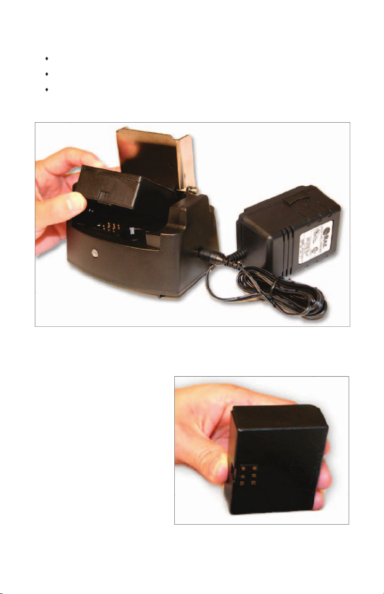
The Li-Ion battery pack can be charged alone or while it is installed in
the monitor. To charge an installed battery, simply plug the transformer
cradle. The monitor (or battery) is fully charged when:
The LED on the charging cradle is green
The “Fully Charged” message appears on the display
The segments of the battery icon are blinking.
Page 26
20
To charge the battery pack
alone, place the battery
on the charging cradle.
The monitor (or battery) is still in charging mode when:
The LED on the charging cradle is red
The “Monitor Charging” message appears on the display
The segments of the battery icon are scrolling.
Page 27

Programming Mode
21
The Li-Ion Battery Pack
The factory-supplied Li-ion battery pack is designed to last for 16 hours
of normal operation between charges (without alarm or back light
conditions). The rechargeable batteries have a 1-year warranty. Age,
ambient temperature, and heavy usage may impact battery life.
cradle. The battery can trickle-charge when not in use.
voltage will be low. Fully charge battery packs before going into the eld,
and recharge them upon returning from the eld.
To reduce the risk of ignition of hazardous atmospheres, recharge
battery only in areas known to be non-hazardous. Remove and replace
battery only in areas known to be non-hazardous.
dangereux.
settings to their requirements using the Programming Mode.
Monitoring gas concentrations pauses during Programming Mode
and during calibration. Datalogging also pauses during Programming
Security
access Programming Mode. The default password is “0000.” To enable
“Change Pass?” on page 26.)
!
Page 28

22
Programming Mode
Fresh Air Calibration? Must be in clean ambient air.
Span Calibration? Must use four-gas calibration mix (CO, H
2
S, O
2
and LEL).
Span Calibration? Must use 100 ppm Isobutylene gas (PID).
Zero Calibration? Must use Nitrogen 100%.
Calibration Due Day? Sets a reminder. Default: 30 days, Max: 365 days
Set Type? Auto Alarm Reset or Latch. Default: Auto
Set Run Silent? Runs in Silent Mode. Default: No
Adjust HIGH? Adjusts High Alarm presets.
Adjust LOW? Adjusts Low Alarm presets.
Adjust TWA? Adjusts TWA presets.
Adjust STEL? Adjusts STEL presets.
Enable Sensor? Enable or disable sensor.
Adjust Date? Adjust date and time.
Set LEL Unit? (This function is not available.)
Change Password? Change the password. Default: 0000
Secure Beep? Lets user know monitor is on. If on, beeps once per minute.
Monitor Mode (Sensor Reading Display)
Press
Y or N
Press
MODE & N
Press
MODE
Page 29

Programming Mode
23
together until the first program
to cycle through the submenu options.
3.
to enter a submenu.
4.
To modify a value, use
Y
to increase and
N
to
decrease.
5.
from sensor to sensor.
6.
When the “?” appears at the bottom of the display,
to save changes (or
to cancel changes)
and exit the submenu.
To discard changes or exit the Programming Mode,
Change Monitor Setup
The following submenus represent the programmable setup of the
Refer to
on page 11.
Span Calibration CO, H
S, LEL?
Refer to “Span
Gas Calibration for Multiple Sensors” on page 11 to
calibrate the CO, H
2
S and LEL sensors.
Page 30

24
Programming Mode
Span Calibration VOC?
Refer to “Span Gas Calibration
for the PID Sensor” on page 13.
Zero Calibration?
Oxygen Sensor” on page 14.
Calib Due Day?
calibrate regularly. Enter the number of days between
calibrations per your company’s standards. After 30 days
of no calibration, the monitor sounds. Once the monitor
Set Type?
Choose either automatic alarm reset or
latched (constant) alarm. To acknowledge and reset a
latched alarm, press
Y.
Set Run Silent?
Y
to let the monitor run in silent
during alarm conditions.
N
to let the audible alarm sound during alarm
conditions.
Adjust Alarm Limits?
- The highest reading for each gas concentration
since the monitor was turned on; updated every second.
to reset the high values.
Page 31

Programming Mode
25
– The lowest reading for each gas concentration
since the monitor was turned on, updated every second.
Y
to reset the minimum values.
TWA
- The Time Weighted Average for CO, H
2
S, and
VOC gases only; the accumulated reading of the gas
concentration, divided by 8 hours, since the monitor was
turned on. Updated every minute.
STEL
- The Short Term Exposure Limit for CO, H
2
S,
and VOC gases only; the average reading of the gas
concentration for the last 15 minutes, which is updated
every minute. Dashes “- - -” appear in the display for the
first 15 minutes.
a disabled sensor does not measure or display the
gas concentration. Use this if a sensor has failed or is
sensor to sensor. “Yes” means the sensor is enabled;
likewise, “No” means the sensor is disabled. Press
Y
to
enable or press
N
to disable.
Adjust Date?
Set the date and time using the standard
24-hour format.
Page 32

26
Programming Mode
Change Pass? (Password)
Set a four-digit password,
which is used to access Programming Mode. (Refer to
“Security” on page 21.)
Secure Beep?
Set LEL Unit?
The EntryRAE provides the option of
displaying the concentration of combustibles gases in
%LEL or %Vol.
Page 33

Maintenance
27
To reduce the risk of ignition of hazardous atmospheres, recharge the
battery only in areas known to be non-hazardous. Remove and replace
the battery only in areas known to be non-hazardous.
dangereux.
température de fonctionnement entre -4º à 122º F (-20º à 50º C).
(-20º to 50º C).
-4º à 122º F (-20º à 50º C).
The battery compartment is located on the back of the monitor.
screws with a screwdriver or a coin.
case screws for battery compartment
!
!
!
Page 34

28
Maintenance
The spent battery pack may be charged on the charging cradle by itself.
(Refer to “Charging the Li-Ion Battery Pack” on page 19.)
Page 35

Maintenance
29
the Li-Ion battery pack. The adapter (P/N 046-
3051-000) accepts four AA alkaline batteries (use
only Duracell MN1500 or Energizer 91) to provide
approximately 12 to 14 hours of operation.
adapter, making sure the battery polarity is correct.
The monitor automatically detects the alkaline batteries.
Page 36

30
Maintenance
Sensor Replacement
sensitivity after the expected operating life and need to be replaced.
Warranties: The oxygen (O
), combustible gas (LEL), hydrogen sul de
(H
S) and carbon monoxide (CO) sensors all have a 2-year warranty.
The PID sensor has 1 year warranty.
The sensors are located inside the front of the monitor.
See Technical Note TN-114, Sensor Speci cations And
Cross-Sensitivities, for additional information, available at
www.raesystems.com.
2
S
O
2
CO
Page 37

Maintenance
31
To replace a sensor
2. Remove the front sensor cover by
loosening the two screws on the
back
of the monitor below the battery cover.
See Figure 13.
3. Push the screws from the back of the
(Figure 14).
4. Using the sensor puller, remove the
sensor by carefully pulling straight out
(Figure 15).
The colored dots marked next to each
sensor socket should match the color
of the sensors.
5. To install new sensors, re-align the
dots on the sensors with the dots on
the monitor.
6. Press the sensors all the way into the
socket.
7. Replace the monitor cover and tighten
the screws in the back.
screws.
sensor puller to
Page 38

32
Maintenance
8. Turn the monitor on and the newly installed sensors should be
9.
Calibrate all sensors prior to use.
CO Sensor Charcoal Filter
The carbon monoxide (CO) sensor may be sensitive to hydrocarbons, so
use a charcoal lter (P/N 008-3006-005) to reduce or eliminate organic
vapor contamination or cross-sensitivity. The charcoal lter is installed in
the gas plate above the CO sensor. Under normal operation conditions,
the charcoal lter lasts from four to six weeks before it needs to be
VOC gases for a prolonged period of time, the carbon lter needs to be
The CO charcoal lter lowers the reading if it is accidentally used
on other sensors.
Page 39

Maintenance
33
Cleaning the PID
If the PID does not calibrate, it may need to be cleaned. Be sure to use
The pump in the EntryRAE is not eld replaceable. Call RAE Systems
Technical Support or an authorized service center when the pump needs
to be replaced.
the specially shaped swab included in the PID Cleaning Kit (p/n 5000014-010), shown in the Equipment List, to clean the PID.
1. Open the sensor compartment.
2. Remove sensor with sensor puller (follow procedure on page 31).
3. Using a swab, drip a little bit methanol on the lamp window through
the openings on the top of the PID.
4. Use the swab to carefully clean the lamp window through the two
openings.
5. Leave the PID to dry by itself for ve minutes.
the PID.
Page 40

34
Maintenance
Setting Pump Stall Threshold
This section should only be used by authorized technical users.
only be done if your EntryRAE is going into a pump alarm when the
when you block the pump inlet by holding your nger over it.
diagnostic screen blanks. Then release the keys
and the values reappear.
2. Press @ 7 times to cycle through the diagnostic
screens until you reach the pump diagnostic
screen. The rst, CO, H
2
S, O
2
time screens are used for factory operation and
testing only. The pump diagnostic screen displays
a high and low pump rate. The rst digit of the last
3. To set the pump stall alarm, write down the “Hi”
value as found, and then block the pump inlet
while the pump is running (about 5 seconds), until
the “Hi” reading stabilizes.
4. Write down the new “Hi” value. Add the two “Hi”
values together, and then divide by two to get the
average value.
5. Enter the average into the bottom number on the
screen using the Y and N keys to increase and
decrease the digits, and @ to move between
digits.
6. Once the average is entered, press @ until you
see the blinking “?”. Press Y to save the pump
stall threshold value.
7. Exit the diagnostic mode by pressing @ and Y
together until the screen changes. Gas readings
Page 41

Specifications
35
Speci cations
Size
5.9" L x 3.3" W x 1.9" H (15 x 8.5 x 1.9 cm) without clip
Weight
20 oz with battery (567 g) and clip
Sensors (5)
Protected catalytic bead for combustible gases
Electrochemical sensors for oxygen and toxic gases
Photoionization detector for VOC broadband detection using 10.6 eV lamp
Battery
Drop-in rechargeable Li-ion battery pack
Standard alkaline battery adapter
Charging cradle doubles as external battery changer
Operating Hours
Battery Operation
Temperature
-4º to 113º F (-20º to 45º C)
Battery Storage
Temperature
-4º to 122º F (-20º to 50º C)
Display
Large 1.4" x 1.8" (3.5 x 4.5 cm) segmented display with LED back light
Keypad
Three-button operation
Direct Readout
Oxygen as percentage by volume
Combustible gas as %LEL or %Vol
VOCs, CO and H
2
S as parts per million
TWA and STEL values for VOCs, CO and H
2
S
Battery life displayed as icon in 1/4 increments
Alarms
Audible: 95dB at 30 cm
Visible: Bright LED bar visible from top, front and sides
Sensory: Built-in vibration alarm
Low: 2 beeps and ashes per second
STEL and TWA: 1 beep and ash per second
Low battery displays empty battery symbol, beep per second
EMI/RFI
IP Rating
water from all directions
Datalogging
Wrapping 120 hours ( ve days) of data at one minute intervals for all
ve sensors
Communication
PC-to-EntryRAE via RS-232 through charging cradle, with USB adapter
Calibration
Two-point eld calibration for zero and span gas
Sampling Pump
Low Flow Alarm
Auto shut-off at low- ow condition
Minimum Pump
Flow
Operation
Temperature
-4
o
to 122
o
o
to 50
o
C)
Storage
Temperature
o
to 126
o
o
to 47
o
C)
Humidity
0% to 95% relative humidity (non-condensing)
Pressure
Attachments
Stainless steel alligator clip (installed), wrist strap
Warranty
Lifetime on non-consuming components (per RAE Standard Warranty),
2 years for O
2
2
S sensors, 1 year for PID, 1 year for
pump, 1 year for battery
Page 42

36
Specifications
Certification
UL: Class I, Groups A, B, C, D, T3C
CE 0575
DEMKO 04 ATEX 0419092X
Eex ia d IIC T4
Monitor label (enlarged).
Sensor Range and Resolution
Sensor
Range
Resolution
PID
0-999 ppm VOC
Oxygen (O
2
)
0-30.0%
0.1
Combustible Gas (LEL)
0-100% LEL
Carbon Monoxide (CO)
0-500 ppm
2
S)
0-100 ppm
Note that each sensor has cross-sensitivities to multiple gases. Information on
these sensitivities is available in Technical Notes TN-114 and TN-144, available at
www.raesystems.com. Additional information about sensor calibration and expiration is also
available in these Technical Notes.
Page 43

Specifications
37
Service and Repair Record
Service / Repair Type
Page 44

RAE Systems World Headquarters
www.raesystems.com
3775 N. First St.
San Jose, CA 95134-1708 USA
Phone: 408.952.8200
Fax: 408.952.8480
E-mail: customerserv@raesystems.com
Web Site: www.raesystems.com
RAE Systems Technical Support
Monday through Friday, 7:00AM to 5:00PM Paci c Time
+1.888.723.4800 (toll-free)
email: tech@raesystems.com
RAE Systems Tubes
RAE Systems Europe ApS
Orestads Boulevard 69
DK-2300 Copenhagen, DENMARK
Phone: +45.8652.5155
Fax: +45.8652.5177
RAE Systems (Hong Kong) Ltd.
Room 8, 6/F, Hong Leong Plaza
33 Lok Yip Road
Fanling, N.T. HONG KONG
Phone: +852.2669.0828
Fax: +852.2669.0803
: 888.RAE.TUBE (888.723.8823)
P/N 046-4001-000
Rev C, June 2005
 Loading...