

Page 1

User Manual
Scales of Y series
Manual number:
ITKU-43-13-01-13-A
• WLY Scales
• WPY Scales
MANUFACTURER OF ELECTRONIC
WEIGHING INSTRUMENTS
RADWAG Wagi Elektroniczne, 26–600 Radom, Bracka 28, POLAND
Phone +48 48 38 48 800, fax. +48 48 385 00 10
export@radwag.com
www.radwag.com
Page 2

2
JANUARY 2013
Page 3

3
Table OF CONTENTS
1. INTENDED USE .................................................................................................................................................. 8
2. PRECAUTIONARY MEASURES ....................................................................................................................... 8
3. WARRANTY CONDITIONS ................................................................................................................................ 8
4. UNPACKING AND MOUNTING ......................................................................................................................... 9
4.1. Scales of Y/C series ..................................................................................................................................... 9
4.2. Scales of Y/2/D2 series ..............................................................................................................................10
5. SCALE STRUCTURE .......................................................................................................................................10
5.1. Main dimensions .........................................................................................................................................10
5.1.1. Scales of Y/C series ........................................................................................................................10
5.1.2. Scales of Y/2/D2 series ...................................................................................................................12
5.2. Description of connectors ...........................................................................................................................13
5.2.1. Connectors’ description in PUE 7 ...................................................................................................13
5.2.2. Connectors’ description in PUE 7P.................................................................................................13
5.2.3. Description of glands PUE 7P ........................................................................................................13
5.2.4. Connector with RS232 and I/O .......................................................................................................14
6. GETTING STARTED ........................................................................................................................................14
7. KEYPAD OVERLAY .........................................................................................................................................15
8. FUNCTIONS OF KEYS .....................................................................................................................................15
9. PROGRAM STRUCTURE ................................................................................................................................16
9.1. Main menu items.........................................................................................................................................16
9.2. Inventory of parameters ..............................................................................................................................17
9.2.1. Scale parameters - weighing ..........................................................................................................17
9.2.2. Working modes ...............................................................................................................................17
9.2.3. Communication ...............................................................................................................................23
9.2.4. Devices............................................................................................................................................24
9.2.5. Display.............................................................................................................................................26
9.2.6. Inputs / Outputs ...............................................................................................................................28
9.2.7. Authorization ...................................................................................................................................28
9.2.8. Units ................................................................................................................................................29
9.2.9. Other ...............................................................................................................................................30
9.2.10. User Adjustment ............................................................................................................................30
9.2.11. Info .................................................................................................................................................30
9.2.12. Update ...........................................................................................................................................31
10. INDICATING WINDOW ..................................................................................................................................31
10.1. Upper bar ..................................................................................................................................................32
10.2. Weighing window ......................................................................................................................................32
10.3. Workspace ................................................................................................................................................32
10.4. Function keys............................................................................................................................................33
11. LOGGING IN ...................................................................................................................................................33
11.1. Logging in procedure ................................................................................................................................33
11.2. Logging out procedure..............................................................................................................................34
11.3. Authorization access levels ......................................................................................................................34
12. NAVIGATING WITHIN THE MENU ................................................................................................................36
12.1. Keys ..........................................................................................................................................................36
12.2. Return to weighing ....................................................................................................................................37
13. WEIGHING ......................................................................................................................................................37
13.1. Conditions of operational use ...................................................................................................................37
13.2. Zeroing ......................................................................................................................................................39
13.3. Tarring ......................................................................................................................................................39
13.4. Inscribing tare ...........................................................................................................................................39
13.5. Weighing for dual range scales ................................................................................................................40
13.6. Toggling between weighing units .............................................................................................................40
14. SCALE PARAMETERS ..................................................................................................................................41
14.1. Median filter ..............................................................................................................................................41
Page 4

4
14.2. Filter ..........................................................................................................................................................42
14.3. Autozero ...................................................................................................................................................42
14.4. Minimum weight for different functions (LO) ............................................................................................43
14.5. Last digit ...................................................................................................................................................43
15. COMMUNICATION .........................................................................................................................................44
15.1. RS 232 settings ........................................................................................................................................44
15.2. ETHERNET setting ...................................................................................................................................45
15.3. TCP protocol setting .................................................................................................................................45
16. DEVICES .........................................................................................................................................................46
16.1. Computer ..................................................................................................................................................46
16.1.1. Computer port ................................................................................................................................46
16.1.2. Computer address .........................................................................................................................47
16.1.3. Continuous transmission ...............................................................................................................47
16.1.4. Weighing printout template ............................................................................................................47
16.1.5. Cooperation with “E2R System” ....................................................................................................48
16.2. Printer .......................................................................................................................................................49
16.2.1. Printer port .....................................................................................................................................50
16.2.2. Printer code page ..........................................................................................................................50
16.2.3. Templates for printouts ..................................................................................................................50
16.3. Barcode scanner ......................................................................................................................................52
16.3.1. Port for barcode scanner ...............................................................................................................53
16.3.2. Prefix / Suffix .................................................................................................................................53
16.3.3. Field selection ................................................................................................................................53
16.3.4. Test ................................................................................................................................................55
16.4. Transponder card reader ..........................................................................................................................56
16.4.1. Com port for transponder card readers .........................................................................................56
16.4.2. Procedure of attributing the card number to an operator ..............................................................57
16.5. Additional display ......................................................................................................................................57
16.5.1. Additional displ ay port ...................................................................................................................57
16.5.2. Communication protocol frame .....................................................................................................58
17. DISPLAY .........................................................................................................................................................59
17.1. Text strings ...............................................................................................................................................59
17.1.1. Display templates ..........................................................................................................................60
17.2. Function keys............................................................................................................................................62
17.3. Displaying platforms .................................................................................................................................66
17.4. Bargraph ...................................................................................................................................................67
17.4.1. Bargraph type ................................................................................................................................67
17.4.2. Bargraph “Quick weighing” ............................................................................................................67
17.4.3. Bargraph “Signalling of checkweighing ranges”............................................................................69
17.4.4. Bargraph type: „Linear” .................................................................................................................70
17.4.5. “Control” bargraph .........................................................................................................................71
18. INPUTS / OUTPUTS .......................................................................................................................................72
18.1. Configuration of inputs..............................................................................................................................72
18.2. Configuration of outputs ...........................................................................................................................73
19. AUTHORIZATION...........................................................................................................................................74
19.1. Anonymous Operator ...............................................................................................................................74
19.2. Date and time ...........................................................................................................................................74
19.3. Printouts ....................................................................................................................................................75
19.4. Databases .................................................................................................................................................75
19.5. Delete older data ......................................................................................................................................76
20. UNITS ..............................................................................................................................................................77
20.1. Units accessibility .....................................................................................................................................77
20.2. Start unit ...................................................................................................................................................77
20.3. User defined units .....................................................................................................................................78
20.4. Accelerati on of gravity ..............................................................................................................................79
21. OTHER PARAMETERS .................................................................................................................................79
21.1. Languages ................................................................................................................................................79
21.2. Setting date and time ................................................................................................................................80
21.3. Sound signal .............................................................................................................................................80
Page 5

5
21.4. Touch panel calibration ............................................................................................................................80
21.5. Screen brightness .....................................................................................................................................81
21.6. Cursor .......................................................................................................................................................81
22. USER ADJUSTMENT .....................................................................................................................................82
22.1. Adjusting procedure ..................................................................................................................................82
22.2. Start mass adjustment ..............................................................................................................................83
22.3. Report from adjustment process ..............................................................................................................84
22.4. Adjustment track record............................................................................................................................85
23. SOFTWARE UPDATE ....................................................................................................................................85
23.1. ON-LINE updating ....................................................................................................................................85
23.2. Update from pendrive ...............................................................................................................................87
23.3. Changes in software .................................................................................................................................88
24. SPECIAL FUNCTIONS OF WORKING MODES ...........................................................................................88
24.1. Working modes accessibility ....................................................................................................................90
24.2. Recording mode .......................................................................................................................................90
24.3. Down-weighing .........................................................................................................................................91
24.4. Checkweighing .........................................................................................................................................91
24.5. Tare mode ................................................................................................................................................91
24.6. Labelling mode .........................................................................................................................................92
24.6.1. Setting of the number of labels to print .........................................................................................93
24.6.2. Setting of the number of cum ulative labels to print .......................................................................93
24.6.3. Setting of the number of CC labels to print ...................................................................................93
24.6.4. Automatic triggering of cum ulative labels......................................................................................94
24.6.5. Automatic triggering cumulative labels of cumulative labels.........................................................95
24.7. Statistics ...................................................................................................................................................97
24.8. Peak hold ..................................................................................................................................................97
25. WORKING MODE - WEIGHING .....................................................................................................................98
25.1. Starting the working mode ........................................................................................................................98
25.2. Local setting of a working mode ...............................................................................................................99
26. WORKING MODES – PARTS COUNTING ...................................................................................................99
26.1. Starting the working mode ........................................................................................................................99
26.2. Local settings of the working mode ........................................................................................................100
26.2.1. Automatic correction of reference mass......................................................................................100
26.2.2. Minimum reference mass ............................................................................................................101
26.3. Setting a reference unit by entering known piece mass ........................................................................102
26.4. Setting a reference unit by weighing a sample ......................................................................................102
26.5. Setting the reference mass by entering single piece mass directly to the database .............................103
26.6. Inscribing the unit mass to the database ................................................................................................104
27. WORKING MODES – PERCENT SETUP (DEVIATIONS) ..........................................................................104
27.1. Starting the operating mode ...................................................................................................................104
27.2. Local settings of the working mode ........................................................................................................105
27.3. Reference unit mass estimated by weighing..........................................................................................105
27.4. Rederence unit mass inscribing into the memory ..................................................................................105
28. WORKING MODES - DOSING .....................................................................................................................106
28.1. Starting the working mode ......................................................................................................................106
28.2. Dosing process structure ........................................................................................................................107
28.3. Local setting of a working mode .............................................................................................................107
28.4. Description of functions and setting dosing process ..............................................................................108
28.5. Creating a new dosing process ..............................................................................................................110
28.6. Instances of dosing processes ...............................................................................................................111
28.6.1. Instance 1 – Manual dosing process of 4 ingredients on 2 weighing platforms .........................111
28.6.2. Instance 2 – Automatic dosing of 2 ingredients on 2 weighing platforms ...................................114
28.6.3. Instance 3 – Mixed dosing process .............................................................................................116
28.7. Reporting of completed dosing processes .............................................................................................118
29. WORKING MODES – FORMULATION .......................................................................................................119
29.1. Starting the working mode ......................................................................................................................119
29.2. Local setting of a working mode .............................................................................................................120
29.3. Creating a new formulation ....................................................................................................................121
Page 6

6
29.4. Formula making process ........................................................................................................................124
29.5. Reporting from completed formula making processes...........................................................................126
30. WORKING MODE – CPG (CONTROL OF PREPACKED GOODS) ...........................................................127
30.1. Starting the working mode ......................................................................................................................128
30.2. Control settings mode window ...............................................................................................................129
30.3. Local setting of a working mode .............................................................................................................130
30.4. Editing a product to be controlled ...........................................................................................................130
30.5. Control start procedure ...........................................................................................................................132
30.6. Control aborting procedure .....................................................................................................................133
30.7. Logging out from a control process in progress .....................................................................................134
30.8. Non-destructive average tare control mode ...........................................................................................135
30.9. Performing non-distructive testing in mode Empty-Full .........................................................................142
30.10. Performing distructive testing in modes Empty-Full and Full-Empty ....................................................144
30.11. Control in accordance with internal criteria ...........................................................................................144
30.12. Simultaneous carrying out two control processes ................................................................................146
30.13. Report from estimating average tare ....................................................................................................148
30.14. Report from product testing ..................................................................................................................149
31. WORKING MODES – DENSITY ..................................................................................................................152
31.1. Starting the working mode ......................................................................................................................152
31.2. Local setting of a working mode .............................................................................................................152
31.3. Carrying out density determination procedure .......................................................................................153
31.3.1. Determining density of liquids .....................................................................................................153
31.3.2. Determining density of solids ......................................................................................................155
31.3.3. Determining density of pycnometer .............................................................................................156
31.3.4. Determining density of a porous body .........................................................................................158
31.4. Reporting from completed density determination processes .................................................................160
31.5. Table of density parameter for water .....................................................................................................161
31.6. Table of density parameter for ethyl alcohol ..........................................................................................161
32. WORKING MODES – ANIMAL WEIGHING ................................................................................................162
32.1. Starting the operating mode ...................................................................................................................162
32.2. Local setting of a working mode .............................................................................................................162
32.3. Carrying out animals weighing procedure ..............................................................................................163
33. DATABASES ................................................................................................................................................163
33.1. Searching databases ..............................................................................................................................164
33.1.1. Quick name search......................................................................................................................165
33.1.2. Quick code search .......................................................................................................................165
33.1.3. Weighing date search ..................................................................................................................165
33.2. Adding new items in databases..............................................................................................................166
33.3. Deleting items in databases ...................................................................................................................166
33.4. Deleting older data .................................................................................................................................166
33.5. Printing items from databases ................................................................................................................167
33.6. Export a database to a file ......................................................................................................................168
33.7. Database edition .....................................................................................................................................170
33.7.1. Operators’ database ....................................................................................................................170
33.7.2. Database of products ..................................................................................................................170
33.7.3. Database of Weighings / Alibi .....................................................................................................172
33.7.4. Database of clients ......................................................................................................................173
33.7.5. Databse of dosing processes ......................................................................................................174
33.7.6. Database of reports from dosing .................................................................................................175
33.7.7. Database of formulations ............................................................................................................175
33.7.8. Database of reports from formulation ..........................................................................................176
33.7.9. Database of density .....................................................................................................................176
33.7.10. Database of controls .................................................................................................................178
33.7.11. Database of average tares ........................................................................................................179
33.7.12. Database of packages ..............................................................................................................180
33.7.13. Database of warehouses ..........................................................................................................180
33.7.14. Database of labels .....................................................................................................................181
33.7.15. Database of universal variables ................................................................................................181
33.7.16. Counter of weighing records .....................................................................................................182
Page 7

7
34. COMMUNICATION PROTOCOL .................................................................................................................183
34.1. General information ................................................................................................................................183
34.2. List of RS commands .............................................................................................................................183
34.3. Respond message format ......................................................................................................................184
34.4. Command’s description ..........................................................................................................................184
34.4.1. Zeroing .........................................................................................................................................184
34.4.2. Tarring .........................................................................................................................................185
34.4.3. Get tare value ..............................................................................................................................185
34.4.4. Set tare value ..............................................................................................................................185
34.4.5. Send the stable result in basic unit .............................................................................................186
34.4.6. Send the result immediatel y in basic unit ....................................................................................186
34.4.7. Send immediate results from all platforms in basic units ............................................................187
34.4.8. Send the stable result in current unit ...........................................................................................187
34.4.9. Send the result immediatel y in current unit .................................................................................188
34.4.10. Switch on continuous transmission in basic unit .......................................................................189
34.4.11. Switch off continuous transmission in basic unit .......................................................................189
34.4.12. Switch on continuous transmission in current unit ....................................................................189
34.4.13. Switch off continuous transmission in current unit ....................................................................190
34.4.14. Set lower threshold ....................................................................................................................190
34.4.15. Set upper threshold ...................................................................................................................190
34.4.16. Read lower threshold ................................................................................................................190
34.4.17. Read upper threshold ................................................................................................................191
34.4.18. Simulation of pressing ENTER/PRINT key ...............................................................................191
34.4.19. Change platform ........................................................................................................................191
34.4.20. Send all implemented commands .............................................................................................192
34.5. Manual printouts / automatic printouts ...................................................................................................192
35. COOPERATION WITH PERIPHERAL DEVICES ........................................................................................193
36. DIAGRAMS OF CONNECTION CABLES ...................................................................................................193
37. TECHNICAL PARAMETERS .......................................................................................................................195
37.1. Scales of WLY series .............................................................................................................................195
37.2. Scales of WPY series .............................................................................................................................196
37.3. Scales of WLY/KTP series .....................................................................................................................197
37.4. Scales of WPY/KTP series .....................................................................................................................198
38. ERROR MESSAGES ....................................................................................................................................200
39. ADDITIONAL EQUIPMENT..........................................................................................................................200
40. APPENDIX A – Variables for printouts......................................................................................................201
40.1. Inventory of variables .............................................................................................................................201
40.2. Formatting variables ...............................................................................................................................206
40.3. Mathematical function .............................................................................................................................208
41. APPENDIX B – Functions of programmable buttons ..............................................................................210
42. APPENDIX C – Label template ...................................................................................................................214
42.1. Designing a label from the terminal level ...............................................................................................214
42.2. Designing a label on a computer ............................................................................................................215
42.3. Saving label templates in the scale ........................................................................................................219
42.4. Attributing a label to a product ................................................................................................................219
42.5. Attributing a label to a client ...................................................................................................................220
42.6. Printing labels .........................................................................................................................................220
43. APPENDIX D - CITIZEN printer setting .....................................................................................................220
44. APPENDIX E - ZEBRA printer setting .......................................................................................................221
45. APPENDIX F - Communicatio n wi t h bar c ode scanners ..........................................................................221
46. APPENDIX G – Computer Program „ViewerKTP” ...................................................................................222
Page 8

8
1. INTENDED US E
Scales are the response for the market demands concerning simplicity
of operation and high functionality. They are intended for quick and precise
weighing in industrial and laboratory conditions. The state-of-the-art
weighing terminal with TFT 5.7” colourful graphic displays with touch
panels allows for intuitive operation without using keys.
Scales are equipped with 2 USB interfaces, 2 RS232 connectors, port
Ethernet and 4 inputs/4 outputs (digital). They can cooperate with barcode
scanners, receipt printers, label printers, transponder card readers (RFID)
and standard PC equipment: mouse, keyboard, pendrives (limited use).
2. PREC AUTIONARY MEASURES
A. Please, read carefully this user manual before and use the device
according to its intended use;
B. Weighed loads should be placed in possibly central part of scale pan;
C. Do not clean the device with agents causing corrosion;
D. Weighing pan should be loaded with goods having gross mass lower
than maximal capacity of the scale;
E. Do not leave loads on the pan for longer period of time ;
F. In case of failure, immediately disconnect scale power supply;
G. Devices that are to be withdrawn from usage should be utilized
according to the law.
3. W ARRANTY CO NDITIONS
A. RADWAG is obliged to repair or change those elements that appears
to be faulty because of production and construction reason,
B. Defining defects of unclear origin and outlining methods of elimination
can be settled only in participation of a user and the manufacturer
representatives,
C. RADWAG does not take any responsibility connected with destructions
or losses derives from non-authorized or inappropriate (not adequate
to manuals) production or service procedures,
Page 9
9
D. Warranty does not cover:
• Mechanical failures caused by inappropriate maintenance of
the device or failures of thermal or chemical origin or caused
by atmospheric discharge, overvoltage in mains or other
random event,
• Inappropriate cleaning.
E. Forfeiture of warranty appears after:
• Access by an unauthorized service,
• Intrusion into mechanical or electronic construction
of unauthorized people,
• Installing another operating system,
• Removing or destroying protection stickers.
F. The detailed warranty conditions one can find in warranty certificate.
G. Contact with the central authorized service:
+48 48 384 88 00 ext. 106 or 107.
4. UNP ACKING AND MOUNTING
4.1. Scales of Y/C series
A. Take the device out of the package,
B. Put the scale on an even stiff ground,
C. Remove transport protection:
D. Scale should be levelled by turning regulation feet. Levelling is correct
if air bubble is situated in the central position:
Page 10
10
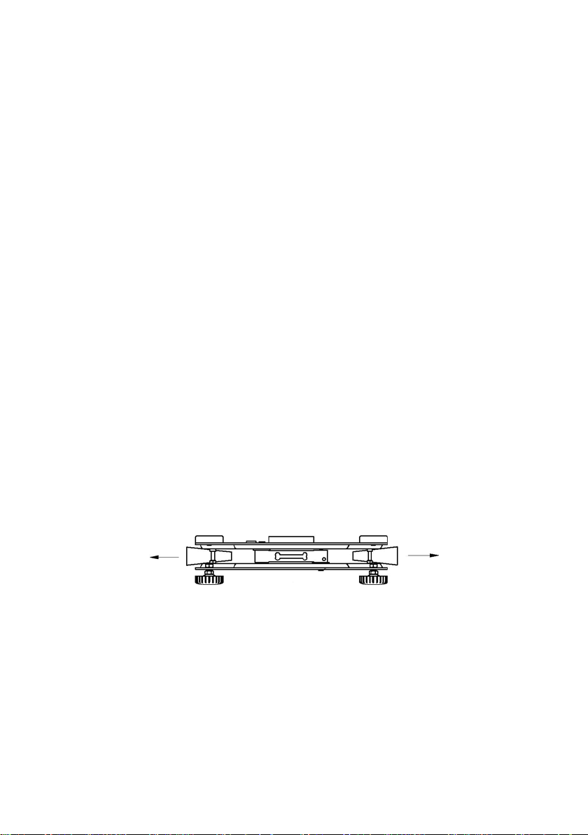
4.2. Scales of Y/2/D2 series
A. Take the device out of the package,
B. Put the scale on an even stiff ground,
C. Fit the pan and the bracket under the device according to the drawing:
E. Scale should be levelled by turning regulation feet. Levelling is correct
if air bubble is situated in the central position:
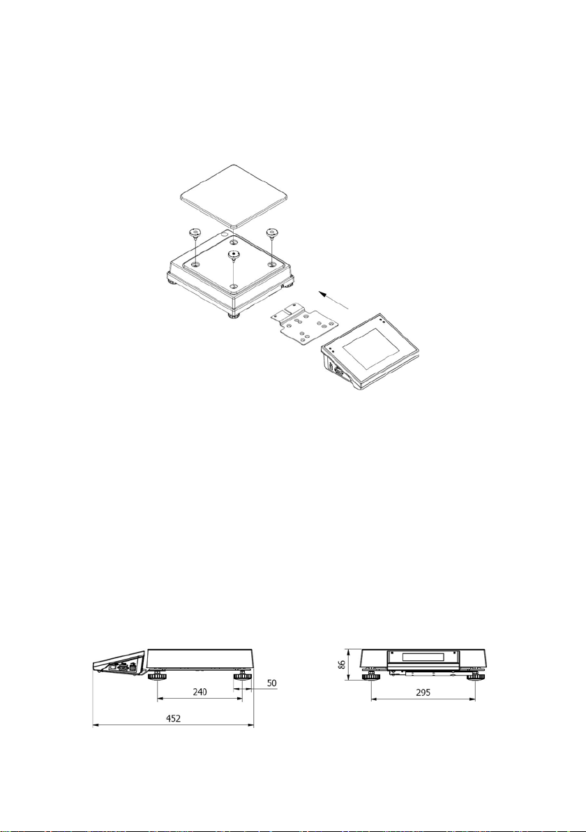
5. SCALE STRUCTURE
5.1. Main dimensions
5.1.1. Scales of Y/C series
Page 11
11
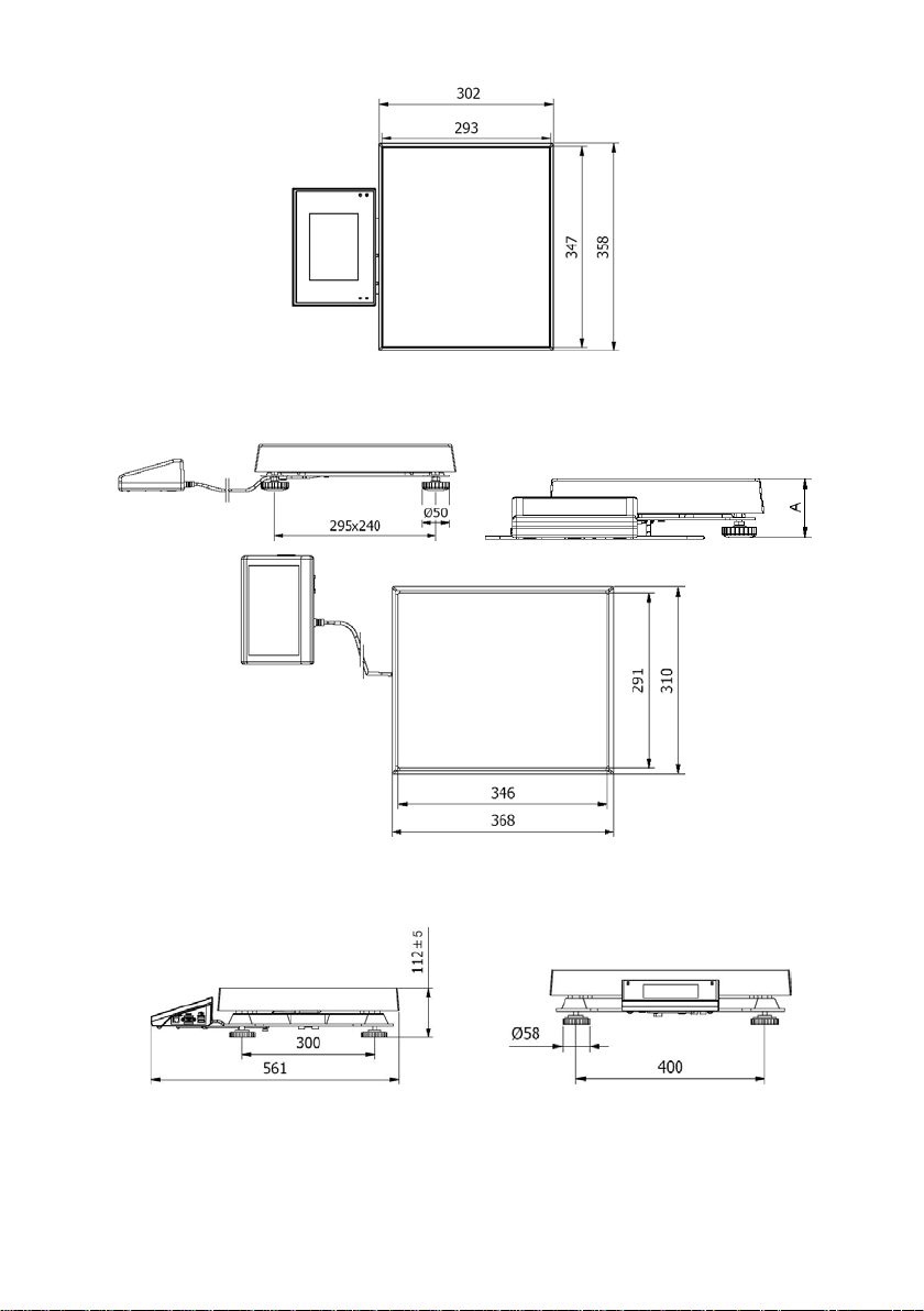
Y/C1/R series – main dimensions
Y/C1/K series – main dimensions
Page 12
12
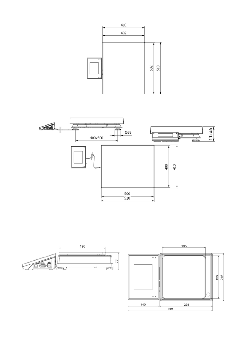
Y/C2/R series – main dimensions
Y/C2/K series – main dimensions
5.1.2. Scales of Y/2/D2 series
Page 13
13
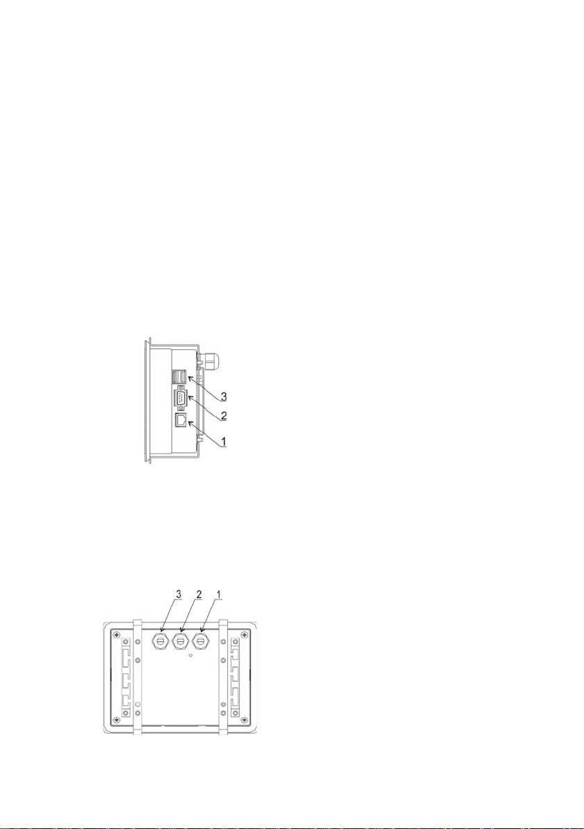
3 – USB
3 – USB
5.2. Description of connectors
5.2.1. Connectors’ description in PUE 7
1 – Ethernet RJ45
2 – RS232 (COM1)
5.2.2. Connectors’ description in PUE 7P
1 – Ethernet RJ45
2 – RS232 (COM1)
5.2.3. Description of glands PUE 7P
1 – power supply socket
2 – I/O, RS232 (COM2)
1 – I/O, RS232 (COM2)
1 – Supply cord gland
2 – Gland for platforms 1, 2
3 – Gland for platforms 3, 4
Page 14

14
5.2.4. Connector with RS232 and I/O
RS232 - DB9/M (male),
top view:
Pin2 - RxD
Pin3 - TxD
Pin5 - GND
I/O, RS232 DSUB15/F (female),
top view:
Pin1 - GNDW E
Pin2 - OUT1
Pin3 - OUT2
Pin4 - COMM
Pin5 - 6÷9VDC
Pin6 - IN4
Pin7 - IN3
Pin8 - TxD2
Pin9 - 5VDC
Pin10 - GNDRS
Pin11 - IN2
Pin12 - IN1
Pin13 - RxD2
Pin14 - OUT4
Pin15 - OUT3
6. GETTING ST ARTED
• After the terminal is connected to power the ON/LOAD
diode starts to light.
• Press
Windows CE together with RADWAG software loading is signalled
by blinking the red diode ON/LOAD.
• When the loading procedure is completed the main software
window appears.
to start the operating system loading procedure.
Page 15

15
7. KEYP AD OVERLAY
8. FUNCTIONS OF KEYS
Key Description
Turning on/off the scale
Zeroing
Tarring
Printing out the result or confirming some entered data
Function key (entering the menu)
Programmable key
Programmable key
Programmable key
Page 16

16
9. PROG RAM STRUCTURE
The main menu has been divided into twelve functional groups.
In every group there are parameters of similar use.
9.1. Main menu items
Pictogram Description
Scale
Databases
Working Modes
Communication
Devices
Display
Inputs / Outputs
Authorization
Units
Other
User Adjustment
Info
Update
Page 17
17
Manual, each
stable
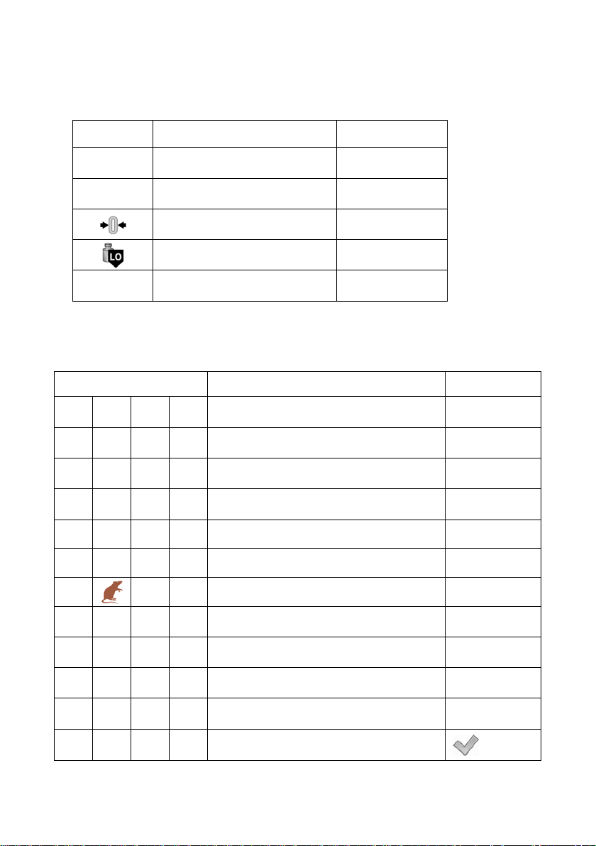
9.2. Inventory of parameters
9.2.1. Scale parameters - weighing
Pictogram Description Value
Median Filter 0.5
Filter Fast
Autozero
LO threshold 0.1
Last digit Always
9.2.2. Working modes
Pictogram Description Value
Accessibility -
Weighing
Parts counting
Percent setup
Dosing
Formulation
Animal weighing
Density
CPG
Weighing -
Save Mode
Down-weighing
Page 18
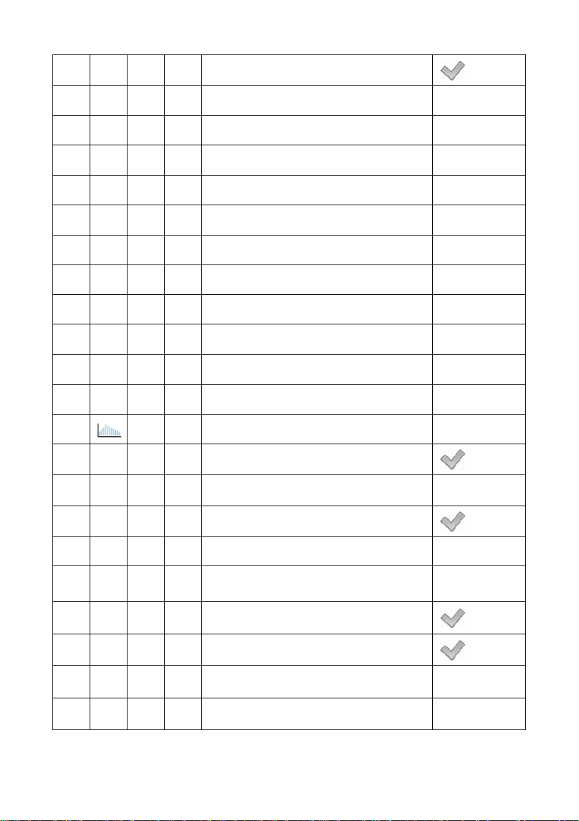
18
Checkweighing
Tare mode Single
Labelling mode -
Number of labels 1
No. of cumulative labels 1
No. of CC labels 1
C label automatic triggering -
Mode None
Threshold 100
CC label automatic triggering -
Mode None
Threshold 100
Statistics Global
Peak hold
Parts counting -
Automatic correction of reference mass
Minimum reference mass 10d
Save Mode
Down-weighing
Checkweighing
Manual, each
stable
Tare mode Single
Labelling mode -
Page 19

19
Manual, each
stable
Number of labels 1
No. of cumulative labels 1
No. of CC labels 1
C label automatic triggering -
Mode None
Threshold 100
CC label automatic triggering -
Mode None
Threshold 100
Statistics Global
Percent setup -
Save Mode
Down-weighing
Checkweighing
Tare mode Single
Labelling mode -
Number of labels 1
No. of cumulative labels 1
No. of CC labels 1
C label automatic triggering -
Mode None
Threshold 100
Page 20
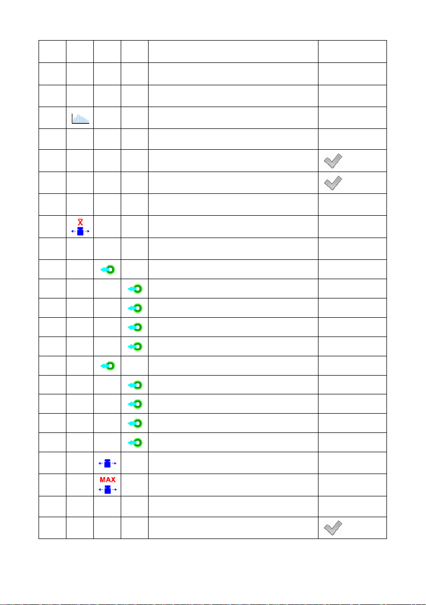
20
No. of weighings for calculating the
correction
CC label automatic triggering -
Statistics Global
Mode None
Threshold 100
Dosing -
Ask for multiplier
Ask for number of cycles
Confirm batching ingredients manually
Global -
Batching outputs -
Output 1 0
Output 2 0
Output 3 0
Output 4 0
Bulk batching output -
0
Formulation -
Ask for multiplier
Output 1 0
Output 2 0
Output 3 0
Output 4 0
Correction 0
Maximum correctional value 0
Page 21
21
Ask for number of cycles
Confirm batching ingredients manually
Automatic tare
Ingredient control
Portion weighing
Report printout
Animal weighing -
Averaging time 5
Automatic mode
Checkweighing
Tare mode Single
Labelling mode -
Number of labels 1
No. of cumulative labels 1
No. of CC labels 1
C label automatic triggering -
Mode None
Threshold 100
CC label automatic triggering -
Mode None
Threshold 100
Statistics Global
Page 22
22
Density -
Standard liquid Water
Temperature 21
Standard liquid density 1
Sinker volume 0
Ask abort sample number
Pycnometer mass 0
Pycnometer density 0
Unit g/cm
Save Mode
Checkweighing
Tare mode Single
Statistics Global
CPG -
3
Manual, each
stable
Save Mode
Number of accessible controls 1
Ask for batch number
Password required
Manual, each
stable
Page 23
23
9.2.3. Communication
Pictogram Description Value
RS 232 (1) -
Baud Rate 9600
Data bits 8
Stop bits 1
Parity None
RS 232 (2) -
Baud Rate 9600
Data bits 8
Stop bits 1
Parity None
Ethernet -
DHCP
IP Address 192.168.0.2
Subnet mask 255.255.255.0
Gateway 192.168.0.1
DNS 192.168.0.1
MAC Address -
Tcp -
Port 4001
Page 24
24
9.2.4. Devices
Pictogram Description Value
Computer
Port None
Address 1
Continuous transmission
Weighing Printout Template -
E2R System -
System is active
Lock selecting products
Printer -
Port RS 232 (1)
Code page 1250
Printouts -
Weighing printout template See ch. 16.2.3
Cumulative printout template See ch. 16.2.3
Cumulative printout template
for cumulative data
See ch. 16.2.3
Adjustment report printout template See ch. 22.3
Dosing report printout template See ch. 28.7
Formulation report printout template See ch. 29.5
Printout Template of an Ingredient
in a Formulation
See ch. 16.2.3
Page 25

25
CPG report printout pattern
(Control of Packacked Goods)
Average tare report printout pattern
(Control of Packacked Goods)
See ch. 30.14
See ch. 30.13
Density printout template See ch. 31.4
Product printout template See ch. 16.2.3
Operator printout template See ch. 16.2.3
Client printout template See ch. 16.2.3
Warehouse printout template See ch. 16.2.3
Package printout template See ch. 16.2.3
Barcode reader -
Port None
Prefix 01
Suffix 0d
Field selection See ch. 16.3.3
Test See ch. 16.3.4
Transponder card reader -
Port None
Additional display -
Port None
Template See ch. 16.5.2
Page 26

26
9.2.5. Display
Pictogram Description Value
Text information -
Displaying template See ch. 17.1.1
Left displaying template See ch. 17.1.1
Right displaying template See ch. 17.1.1
Font -
Type Courier
Font size Small
Bold
Tilt
Colour Black
Background colour Light grey
Set Default -
Button functions See ch. 17.2
Show all platforms
Bargraph -
Bargraph type None
Fast weighing -
MIN, MAX thresholds working mode Unstable
OK threshold working mode Unstable
Min threshold signalling colour Red
OK threshold signalling colour Intense green
Page 27

27
Max threshold signalling colour Red
Gradient
Background colour Black
Frame colour White
Signalling checkweighing ranges -
MIN, MAX thresholds working mode Unstable
OK threshold working mode Unstable
Min threshold signalling colour Red
OK threshold signalling colour Intense green
Max threshold signalling colour Red
Gradient
Background colour Black
Frame colour White
Linear -
Min threshold signalling colour Red
OK threshold signalling colour Green
Max threshold signalling colour Red
Min Max range background colour Turquoise
OK range signalling colour Turquoise
Gradient
Page 28

28
9.2.6. Inputs / Outputs
Pictogram Description Value
Inputs -
9.2.7. Authorization
Pictogram Description Value
Input 1 None
Input 2 None
Input 3 None
Input 4 None
Outputs -
Output 1 None
Output 2 None
Output 3 None
Output 4 None
Anonymous operator Operator
Date & Time Administrator
Printouts Administrator
Databases
Products Administrator
Clients Administrator
Dosing processes Administrator
Page 29

29
Formulations Administrator
9.2.8. Units
Pictogram Description Value
Packages Administrator
Warehouses Administrator
Labels Administrator
Weighing counter Administrator
Delete older data Advanced Operator
Accessibility -
g
ct
lb
oz
N
Start unit None
Defined unit 1 -
Multiplier 0
Name -
Defined unit 1 -
Multiplier 0
Name -
Acceleration of gravity 9.80665
Page 30
30
9.2.9. Other
Pictogram Description Value
Language Polish
Date & Time -
Beep Yes
Touch screen calibration -
Screen brightness -
Cursor
9.2.10. User Adjustment
An option only for non-verified scale
Pictogram Description Value
Setting of start mass -
Adjustment -
Report printout
Adjustment track record -
9.2.11. Info
Submenu < Info> is for viewing information:
• Scale factory number,
• Program version,
• Scale program version.
Page 31

31
9.2.12. Update
Pictogram Description Value
Software version on server Check version
Update from server -
Update from pendrive -
Changes in software -
10. INDICATING WINDOW
Main view:
In the main application window one can see four separate parts:
• Upper bar,
• Weighing window,
• Workspace,
• Function keys.
Page 32

32
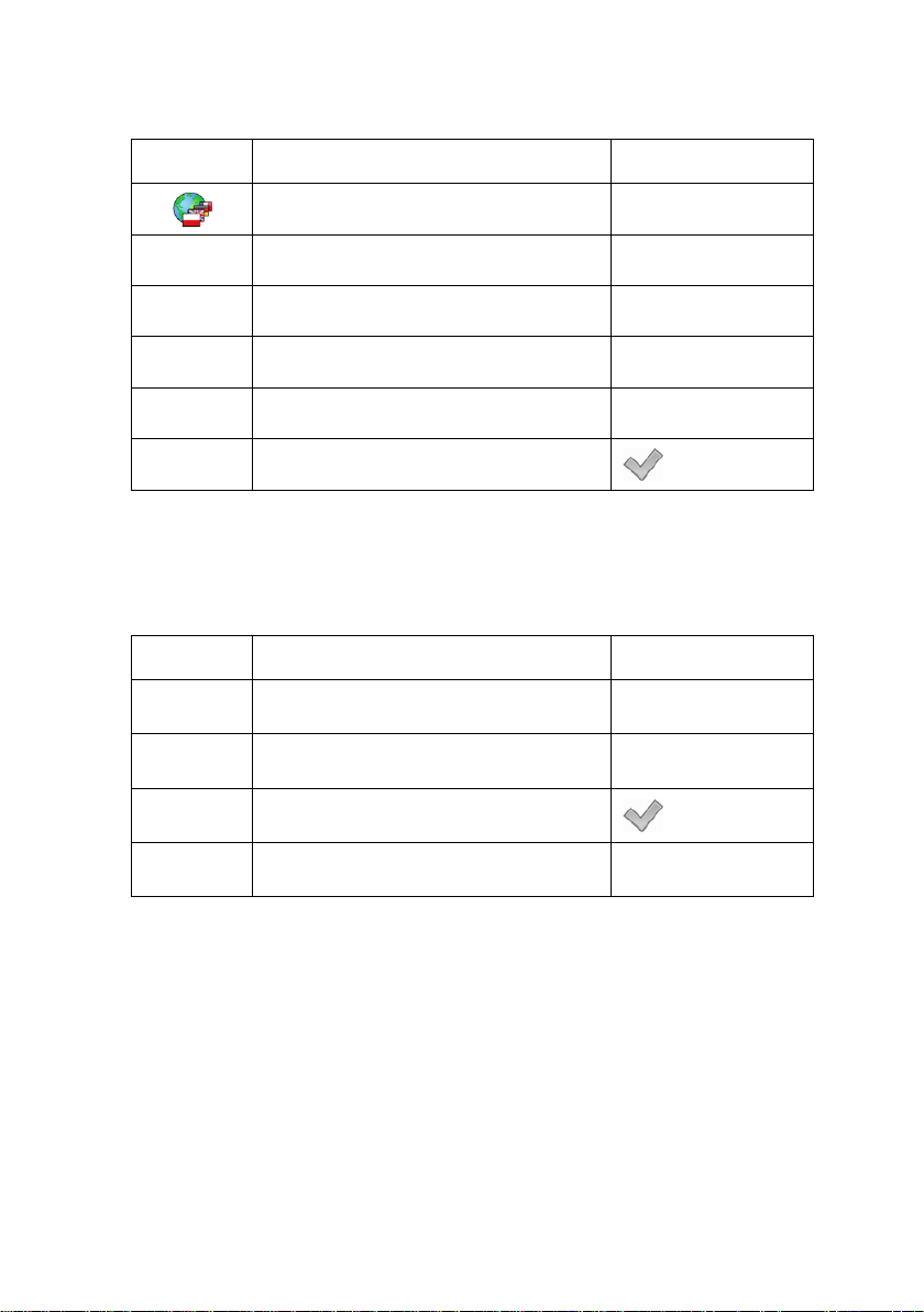
10.1. Upper bar
The upper bar on the display contains the following data:
Pictogram and name of an active working mode
Logged user
Pictogram of an active connection with a computer
Date and time
10.2. Weighing window
The weighing window contains data on carried out weighing process:
10.3. Workspace
The workspace is located under the weighing window:
The workspace features three displaying templates. The upper section of the
workspace comprises a graphic information on which of the three templates
is enabled. Changing of the template is carried out by draging the workspace
to the right or left.
Page 33

33
The data conatined in the workspace is optionally programmable for each of
the working modes. The default template format is described in point 17.1.1
of this user manual.
Notice:
An exception is an “initial workspace window” in the CPG mode, containing a
logo and non-editable anvigating line:
10.4. Function keys
Below the workspace area there is a set of on-screen function keys:
The on-screen function keys are editable in each of the wavailable working
modes. The procedure of enabling/disabling function keys is desribed in
point 17.2 of this user manual.
11. LOGGING IN
In order to have full access to user parameters and databases, the user
should log in as an <Administrator>.
11.1. Logging in procedure
• While in the main window press <log in> text located in the upper bar
of the display and the window with operators attributed to <
will appear,
Admin>
Page 34

34
None
No access to user parameters. No weighing can be confirmed.
• After entering < Admin> a screen keyboard runs with editing
window for inscribing a password,
• Type password „1111” and confirm by pressing
,
• The program returns to the main window and in the title bar you will
see <Admin> instead of <log in>.
11.2. Logging out procedure
• While in the main applilcation window press the name of a logged
in operator in the upper bar on the screen to open the database of
operators,
• Press logging out button situated in the top bar of the operators’
database window:
• The program returns to the main window and in the upper bar the
operators name is substituted by <Log in>.
11.3. Authorization access levels
Weighing software uses four access levels: administrator, advanced
operator, operator, none. Every user with any attributed access level
can perform weighings and select data from in databases to be used
during weighing.
Access to user parameters, databases and working modes depending
on the authorization access level attributed:
Operator type Access level description
Cannot start procedure „CPG”. Cannot enter the reference mass
unit and estimate the reference mase unit by weiging in „Counting
Pieces” and „Deviations”, density determination, carrying out
dosing and formulation making processes. No access to <Export
the weighing database to a file> in menu <Databases>
2)
.
Page 35

35
Operator
Access to parameters in submenu: <Weighing>, <Display>1)
Advanced
Access to parameters in submenus: <Weighing>, <Working
Administrator
Access to all user parameters, functions and databases2).
(excluding the group <Actions>), <Others>1). Can start and
perform all weighing procedures. Access to <Export the
weighing database to a file> in menu <Databases>
2)
.
Operator
modes>, <Communication>, <Devices>1), <Display>1),
<Others>
Access to <Export the weighing database to a file> in menu
<Databases>
1)
. Can start and perform all weighing procedures.
2)
.
Can start and perform all weighing procedures.
1. Authorization level for editing functions:
• < Printouts> in submenu „ Devices / Printer”,
• <
• <
Sample> in submenu „ Devices /
Additional display”,
Displaying template> in submenu „ Display /
Text information”,
• <
Date and Time> in submenu < Others>,
The functions are declared in submenu < Authorizations>, which
is accessable only for users with the <Administrator> authorization
level (see ch. 19 of this manual).
2. A user logged in as <Administrator> in submenu
Authorizations> (see ch. 19 of this manual) can change
<
authorization levels for accessing different databases and functions:
Delete older data>, < Weighing counter>. The exception
<
are database <
Weighings / Alibi>, that have the status „Read
only”.
Page 36

36
12. NAVIGATING WITHIN THE MENU
Owing to the colour display with the touch panel navigating within the menu
is simple and intuitive.
12.1. Keys
Entering the main menu
Menu list „up”
Menu list „down”
Scrolling „up-down”
Enter (OK)
Abort
Add a new item in a database
Disabeling the formerly selected record e.g. logging out the
operator
Searching a database by date
Searching a database by name
Searching a database by code
Printing on item from a database
Exporting reports from testing and average tare
(for testing prepackages mode CPG)
Clearing an editing field
Screen keyboard on / off
Reading a printout template from a *.lb file
(active after connecting a pendrive)
Page 37

37
Saving printout template in a file format *.lb (option enabled
on plugging a portable data storage devic e to scale port )
Variables for a printout template
One level up
Immediate exit to the main window
12.2. Return to weighing
Changes made to the scale’s settings are automatically saved in the memory
on returning to the main software window. The scale provides two ways of
returning to the main window:
• By pressing key for a few times until returning to the main window,
• By pressing
key in the upper bar, which causes immediate returning
to displaying the main window.
13. WEIGHING
Put a load on the weight pan. When pictogram
indication is ready to read.
Notice:
A weighing can be saved after stabilising a measurement (pictogram
13.1. Conditions of operational use
In order to assure a long term operating period with appropriate
measurements following principles should be adhered to:
• Avoid applying mechanical shocks to the weight pan:
is displayed the
).
Page 38

38
• Loads should be placed in the centre of the pan (eccentric errors
are outlined in PN-EN 45501 chapter 3.5 and 3.6.2):
• Do not apply concentrated forces (all load in one point):
• Avoid side loads, particularly side strokes:
Page 39

39
13.2. Zeroing
In order to zero the indication choose a platform on the touch panel and
press
following symbols usually appear:
. After zeroing is performed the indication is equal zero and
and .
Zeroing is possible only when the indication is stable.
Notice:
Zeroing is possible only within ±2% of full range arou n d zero. If the
zeroed value is beyond the interval of ±2%, Err2 is displayed.
13.3. Tarring
In order to tare the scale choose a platform on the touch panel if necessary,
put a package on the pan and press
equal zero and following symbols usually appear: Net and
. You will see the indication
.
After placing a load on the weight pan net mass will be shown. Tarring is
possible within the whole range of the scale. After unloading the pan the
display shows the tarred value with minus sign.
You can also inscribe tare values to the product database. Every product has
a field “Tare”. In that case tare is automatically set to this value after selecting
the product.
Notice:
Tarring cannot be performer when a negative or zero value is being
displayed. In such case Err3 appears on the display.
13.4. Inscribing tare
It is possible to inscribe a tare value.
Procedure:
• While in any work mode press , then the screen keyboard
is displayed,
• Inscribe tare and press
,
Page 40

40
• The program returns to weighing and the and the display shows
the entered value with the „–” sign provided there was zero before
on the display.
13.5. Weighing for dual range scales
Switching between the I range and the II range happens automatically
(exceeding Max of the I range).
Weighings in the second range is signalled by a pictogram in the top left
corner of the display
of the II range to the moment of returning to zero (autozero range
. Then weighings is done with the accuracy
)
where the scale switches back to the I range.
Switching between the II range and I range is automatic both in the
switching point the autozero zone. While in AUTOZERO
appears. Then pictogram
is off and a scale returns to weighing in the
– pictogram
I range.
13.6. Toggling between weighing units
Operators can change the weight unit in two ways:
• Pressing the unit symbol on the screen,
• Pressing formerly defined button <
Change unit>.
Possible selection:
• gram [g]
• kilogram [kg]
• carat [ct]
• pound [lb]
• ounce [oz] *
• Newton [N] *
*) – weighing unit inaccessible in a verified scale
Page 41

41
Notice:
1. The user can also declare the start unit and determine two custom
weighing units (user defined) – see point 20 of this user manual;
2. The procedure of attributing functions to buttons is described in ch.
17.2 of this manual.
14. SCALE PARAMETERS
Users can set the scale according to the ambient conditions (filtering level)
or own needs (autozero) and set the LO threshold for minimum load that
enables operation of some functions. This parameters are placed in
Weighing>.
<
In order to enter submenu < Weighing>, press and then:
„ Weighing”.
Notice:
Weighing parameters are directly related to a specific weighing platform,
so at the beginning the weighing platform should be selected for which
we want to set parameters.
Inventory of scale parameters:
Median Filter
Filter
Autozero
LO Threshold
Last digit
14.1. Median filter
The median filter is intended for eliminating short-lasting mechanical shocks.
Page 42

42
Procedure:
• Enter < Weighing> according to ch. 14 of the manual, select
Median Filter> and then set an appropriate value.
<
Accessible settings:
None - median filter is off
0.5, 1, 1.5, 2, 2.5 - filtering level to choose
14.2. Filter
This filter is intended to suppress continuous mechanical vibrations at the
cost of stabilization time.
Procedure:
• Enter < Weighing> according to ch. 14 of the manual, select
<
Filter> and then set an appropriate value.
Accessible settings:
None, V.Fast, Fast, Average, Slow.
Notice:
The higher filtering level the longer stabilization time.
14.3. Autozero
The autozero function has been implemented in order to assure precise
indications. This function controls and corrects „0” indication.
While the function is active it compares the results continuously with
constant frequency. If two sequentional results differ less than the declared
value of autozero range, so the scale will be automatically zeroed and the
pictograms
and will be displayed.
If AUTOZERO is disabled zero is not corrected automatically. However,
in particular cases, this function can disrupt the measurement process e.g.
slow pouring of liquid or powder on the weighing pan. In this case, it is
advisable to disable the autozero function.
Page 43

43
-
Autozero off
Procedure:
• Enter < Weighing> according to ch. 14 of the manual, select
Autozero> and then set an appropriate value.
<
Accessible settings:
- Autozero on
14.4. Minimum weight for different functions (LO)
Parameter <LO THRESHOLD> is associated with automatic weighing.
Next weighing will not be saved until the indication goes under the
THRESHOLD LO (net).
Procedure:
• After entering < Threshold Lo> according to ch. 14 of this manual
a keyboard is displayed,
• Inscribe LO and confirm by pressing
14.5. Last digit
.
The last digit option < Last digit> is to switch off the last digit of
measured mass indication – the measurement is carried out with decreased
accuracy.
Procedure:
• Enter group of parameters < Weighing> in accordance with ch.
14 of this user manual, select parameter <
Last digit> and set
its desired value.
Page 44

44
Always
-
Last digit always visible
Never
-
Last digit always switched off
When stable
-
Last digit visible only on stable indication of mass
Accessible settings:
15. COMMUNICATION
The scale can communicate with external devices via different ports:
• RS232 (1),
•
•
•
The communication can be configured in parameters’ group
Communication>.
<
In order to enter <
„ Communication”.
15.1. RS 232 settings Procedure:
• Enter < Communication> according to ch.15 of the manual, select
<
value.
For RS 232 following parameters are accessible:
• Baud Rate - 4800, 9600, 19200, 38400, 57600, 115200 bit/s
• Data bits - 5, 6, 7, 8
• Stop Bit - No, 1, 1.5, 2
• Parity - No – Odd – Even – Mark – Space
RS232 (2),
Ethernet,
Tcp.
Communication>, press and then:
RS232 (1)> or < RS232 (1)>, and then set an appropriate
Page 45

45
15.2. ETHERNET setting Procedure:
• Enter < Communication> according to ch.15 of the manual,
select <
Ethernet> and then set an appropriate value.
Following settings are accessible for Ethernet:
• DHCP - Yes – No
• IP Address - 192.168.0.2
• Subnet Mask - 255.255.255.0
• Default gateway - 192.168.0.1
• DNS - 192.168.0.1
• MAC Address - ---
Notice:
1. The above settings are presented for information purpose only.
Transmission parameters have to be selected in accordance with
client’s local network settings.
2. Parameter <MAC Address> is automatical ly assig ned to a device
and it is has <Read only> Attribute.
3. In case of declaring the <DHCP> parameter to value and on device
restart, the other transmission parameters have <Read only> attribute.
• After making changes press key, then a new message is displayed:
<Restart to apply the changes>,
• Go back to weighing and restart the device.
15.3. TCP protocol setting
TCP (Transmission Control Protocol) is a protocol for communication
between two computers. It operates in mode client-server. Server awaits
on connection iniciation on a specified port while client initiates connection
to the server. Scale software allows setting the port for the „Tcp” protocol.
Page 46

46
Procedure:
• Enter < Communication> parameter group as described
in chapter 16 of the manual,
• Select: „
Tcp / Port” then you will see window <Port>
with the screen keyboard,
• Enter the required number and press
.
Notice:
The number of TCP port in RADWAG instruments is set to default value:
4001.
16. DEVICES
16.1. Computer
The scale can cooperate with a computer. Active connection scale-computer
is signalled by icon
<
Computer> some settings needs to be configured for cooperation
with computers.
in the top bar of the main window. In submenu
Enter submenu < Computer>, press and then:
„ Devices / Computer”.
16.1.1. Computer port Procedure:
• Enter parameters’ group < Devices> according to ch.
16 of this manual,
• Select „
Computer / Port” and then set the appropriate option.
The scale can communicate with a computer via following ports:
• RS232 (1),
• RS232 (2),
• Tcp.
Page 47

47
-
Continuous transmission off
16.1.2. Computer address Procedure:
• Enter < Devices> parameter group as described in chapter
16 of the manual,
• Choose „
Computer / Address” then the window <Address>
with the screen keyboard appears,
• Enter the required address and confirm it by pressing
.
16.1.3. Continuous transmission
Users can enable continuous transmission from the scale to a computer.
Setting parameter <
sending data from <
„Setup /
Devices / Computer / Weighing Pr intout
Continuous transmission> starts subsequent
Weighing Printout Template> set in submenu:
Template”.
Procedure:
• Enter parameters’ group < Devices> according to ch. 16 of this
manual,
• Choose „
Computer / Continuous transmission” and then
set an appropriate value.
Accessible settings:
- Continuous transmission on
16.1.4. Weighing printout template
Users in parameter < Weighing Printout Template> can define
variables included in the printout from the scale to a computer.
Page 48

48
Procedure:
• Enter < Devices> parameter group as described in chapter
16 of the manual,
• Choose „
Computer / Weighing Printout Template” then
the editing field <Weighing Printout Template> with the screen
keyboard appears,
• Modify the template if necessary and confirm the changes by pressing
.
Notice:
There are additional buttons in the bottom line of the screen keyboard.
They can be used while modifying a printout template.:
Screen keyboard on/off
Reading a printout template from a *.lb file (button active while
connecting a USB pendrive)
Saving printout template in a file format *.lb (option enabled
on plugging a portable data storage device to scale port)
List of variables for printout templates (see the list in APPENDIX A
of this manual)
Clear the editing field
16.1.5. Cooperation with “E2R System”
Scales can cooperate with computer software „E2R System” that is
a modular system for complex production supervising by monitoring
of weighings processes. In order to allow the cooperation with
„E2R System” enable parameter <
Notice:
The parameter <
E2R System> can be activated by an authorized
service or the manufacturer.
E2R System>.
Page 49

49
-
System is not active
-
System is active
- parameter active < System is active>
Procedure:
• Enter < Devices> parameter group as described in chapter
16 of the manual,
• Choose „ Computer / E2R System / System is active”
and then set an appropriate value.
Accessible settings:
• If during cooperation with <
is required for operators, go to parameter <
products> and set its value to
E2R System> product selection lock
Lock selecting
.
• Active connection with the computer software is indicated by additional
information displayed in the upper bar of the software:
Where:
- active connection with a computer software
16.2. Printer
In < Printer> submenu users can:
• Setting communication with a printer,
• Setting code page of a printer,
• Setting templates of printouts.
To enter <
Printer>, press and then: „ Printer”
Page 50

50
16.2.1. Printer port Procedure:
• Enter < Devices> parameter group as described in chapter 16
of the manual, choose „
Printer / Port” and then select an
appropriate option.
Printers can be attached to:
• RS232 (1),
• RS232 (2),
• USB,
• Tcp.
16.2.2. Printer code page Procedure:
• Enter parameters < Devices> as described in chapter 16
of the manual,
• Choose „
Printer / Code Page” then the screen keyboard
will be displayed,
• Write the required code page and confirm by pressing
Notice:
The default value is 1250 – code page for Middle-East Europ e.
16.2.3. Templates for printouts
.
Enter < Printouts> to define printout templates.
Procedure:
• Enter parameter group < Devices> as described in chapter
16 of the manual, then choose „
Printer / Printouts”,
Page 51

51
Weighing Printout Template
{0}
Cumulative Printout Template
N={15} SUM={16}
Cumulative of Cumulative Printout Template
N2={20} SUM2={21}
Dosing report printout template
See ch. 28.7
Formulation report printout template
See ch. 29.5
Printout Template of an Ingredient in a
-
CPG report printout pattern
See ch. 30.14
Average tare report printout pattern
See ch. 30.13
Density printout template
See ch. 31.4
• After editing a template a memo box with the default content and the
screen keyboard,
• Modify the template according to your requirements and confirm it by
pressing
Notice:
.
There are additional buttons in the bottom line of the screen keyboard.
They can be used while modifying a printout template.:
Screen keyboard on/off
Reading a printout template from a *.lb file (button active while
connecting a USB pendrive)
Saving printout template in a file format *.lb (option enabled
on plugging a portable data st or age dev ic e to scale port)
List of variables for printout templates (see the list in APPENDIX A
of this manual)
Clear the editing field
Default printouts’ settings:
Formulation
(Control of Packaed Goods)
(Control of Packaed Goods)
Page 52

52
Product Printout Template
{50}
Operator Printout Template
{75}
Client Printout Template
{85}
Warehouse Printout Template
{130}
Package Printout Template
{80}
Adjustment report printout template
See ch. 22.3
{51}
16.3. Barcode scanner
The balance allows for cooperation with a barcode scanner. The scanner
can be used for quick search of:
• Products,
• Clients,
• Packages,
• Warehouses,
• Dosing process,
• Formulation,
• Universal variables,
• Lot number,
• Batch number.
Configuration of communication can be configured in:
{76}
{86}
{131}
{81}
{82}
“
Notice:
In submenu <
The detailed description of cooperation scale – barcode scanner can be
found in APPENDIX F in this manual.
/ Devices / Barcode reader”.
Communication> set the baud rate (default 9600b/sec).
Page 53

53
16.3.1. Port for barcode scanner Procedure:
• Enter < Devices> according to ch.16 of the manual, choose
„
Barcode reader / Port” and then set the appropriate value.
Barcode scanners can be connected to:
• RS232 (1),
• RS232 (2).
16.3.2. Prefix / Suffix
Users can edit a prefix < Prefix> or / and suffix < Suffix> in order
to adjust the program to accept transmission frames from the scanner.
Notice:
A special protocol is required in order the code be received by RADWAG
equipment. It is required to program an appropriate prefix and suffix.
Prefix – one byte 01 hexadecimally, suffix one byte 0D hexadecimally.
The detailed description of cooperation scale – barcode scanner can
be found in APPENDIX F in this manual.
Procedure:
• Enter < Barcode Scanner> according to ch.16.3 of the manual,
• Chose parameter <
Prefix> and then enter, using the screen
keyboard, a required value (hexadecimal) and confirm it by pressing
.
• Chose parameter <
Suffix> and then enter, using the screen
keyboard, a required value (hexadecimal) and confirm it by pressing
.
16.3.3. Field selection
This option is connected with selecting data which the program will search
after reading a barcode.
Page 54

54
Procedure:
• Enter < Devices> according to ch.16 of the manual,
• Chose „
Barcode Scanner / Field selection” and then
the following list will be displayed:
Product
Client
Package
Source warehouse
Destination warehouse
Dosing process
Formulation
Universal variable
Lot number
Batch number
• Select an item and then you can edit following parameters:
Filtering
Offset
Code length
Declaring an item, according to which searching
is supposed to be performed
Setting the first significant character in code from
which the comparison with items is performed during
searching. All preceding characters are skipped
Setting the number of characters to be taken for
the search procedure counting form Offset
Start marker
End marker
Start marker declaration
End marker declaration
Page 55

55
searching. All preceding characters are skipped
Destination
warehouse
No, Yes
No, Yes
Notice:
An exception from the above is <
additional submenu <
Ingredient> containing the following parameters:
Formulation>, which features an
Filtering
Offset
Code length
Start marker
End marker
Declaring an item, according to which searching
is supposed to be performed (options: None, Code)
Setting the first significant character in code from
which the comparison with items is performed during
Setting the number of characters to be taken for
the search procedure counting form Offset
Start marker declaration
End marker declaration
Inventory of items to be selected for filtering:
Record Item for filtering
Product None, Name, Code, EAN Code
Client None, Name, Code
Package None, Name, Code
Source warehouse None, Name, Code
None, Name, Code
Dosing process None, Name, Code
Formulation None, Name, Code
Universal variable None, Code
Lot number
Batch number
16.3.4. Test
Operators, using parameter < Test>, can verify if a barcode connected
to the scale works properly.
Page 56

56
Procedure:
• Enter submenu < Barcode Scanner> according to ch. 16.3 of this
manual,
• After entering parameter <
with an ASCII text box and HEX (hexadecimal) field,
Test> window <Test> is opened
• After scanning the code is entered to the ASCII field and HEX filed
and at the bottom of the window a test result is displayed.
When:
• <Prefix> and <Suffix> declared in settings are the same as
<Prefix> and <Suffix> in the read code then the test result is
<Positive>,
• <Prefix> and <Suffix> declared in settings are not the same as
<Prefix> and <Suffix> in the read code then the test result is
<Negative>.
16.4. Transponder card reader
Selecting operator (logging in) can be done in two ways:
• Typing a password on a keyboard,
• Approaching a transponder card to the reader.
The card needs to be registerd first.
Notice:
In case of problems with reading transponder cards check the submenu
Communication> and set appropriate baud rate (default 9600b/s).
<
16.4.1. Com port for transponder card re aders Procedure:
• Enter group of parameters < Devices> according to ch. 16
of this manula, select „
Transponder cards reader / Port”
and set appropriate option.
Page 57

57
The scale can communicate with the reader via following ports:
• RS232 (1),
• RS232 (2).
16.4.2. Procedure of attributing the card number to an operator
To use a transponder card to log on an operator the card needs to be
ascribed to the operator in the database of operators.
Procedure:
• Connect the transponder card reader to the required communication
port (RS 232 (1) or RS 232 (2)),
• Choose a communication port for the reader (see ch. 16.4.1 in this
manual),
• In submenu <
as in the reader (default 9600b/s),
Communication> set the baud rate to the same
• Enter the database of operators and edit the selected operator going
to the field <
• After entering the field <
field <Card Number> with the screen keyboard,
Card Number>,
Card Number> you will see the editing
• Having approached the card to the reader the program automatically
displays in editing field <Card Number> the number of read card,
• Confirm the number by pressing
and return to weighing.
16.5. Additional display
16.5.1. Additional display port Procedure:
• Enter parameters group < Devices> according to ch. 16
of this manual, select „
Additional display / Port”
and then choose an appropriate option from the list.
Page 58

58
{141}
-
Protocol template for WD displays
{142}
-
Protocol template for WWG display
Communication with additional displays can be performed via following
ports:
• RS232 (1),
• RS232 (2),
• Tcp.
16.5.2. Communication protocol frame
Scale with following displays:
• WD display,
• WWG display.
To start cooperation of scale with displays go to parameter
Sample> and define an appropriate communication protocol.
<
Procedure:
• Enter parameters’ group < Devices> according to ch. 16 of this
manual,
• Choose „
<Sample> with the screen keyboard appears,
Additional display / Sample” then the editing field
• Inscribe the required frame template using the screen keyboard or
choose the it from the list after pressing
Specified templates for displays:
• Confirm the changes by pressing
Notice:
In default settings parameter <
(display WD series).
.
.
Sample> has ascribed {141}
Page 59

59
17. DISPLAY
Users can adapt the main display and visible information to their needs.
All parameters of the display can be found in the parameters’ group
Display>. Entering < Display> can be made in two ways:
<
• Pressing and then: „ Display”,
• Direct pressing the workspace area of the main display (does not apply
to the “home screen” and “settings display” of the CPG (Control of
Prepacked Goods mode).
Inventory of parameters of the main disp lay:
Text information
Buton functions *
Show all platforms
Bargraph
*) – In case of the working mode CPG, the function keys are separately defined for:
• Home screen,
• Settings screen,
• Process screen.
17.1. Text strings
In < Text information> users can set:
Display template
Left displaying template
Right displaying template
Font
Data displayed in the workspace.
Detailed description in point 17.1.1.
Submenu on font settings.
Page 60

60
Small, Medium, Large
Available in 18 colours palette.
Default settings for “Text data”
Changing font type for text data
Type
Font size
Bold font
displayed in the workspace. Available
fonts: Arial, Courier.
Declaring font size of text data displayed
in the workspace. Available font size:
.
Bolded font for text data displayed in the
worspace.
Tilt
Colour
Background colour
Set Default
Text data in the workspace in italics.
Font colour for text data in the
workspace. Available in 18 colours
palette.
Colour of the workspace background.
submenu.
17.1.1. Display templates
The main window contains a workspace which displays optionally configured
data specified for each working mode.
The workspace comprises three displaying templates:
• Displaying template,
• Left displaying template,
• Right displaying template.
The upper section of the workspace comprises a graphic information on which
of the three templates is enabled. Changing of the template is carried out by
draging the workspace to the right or left.
Change of the displaying template is carried out in submenu:
“
Procedure:
/ Display / Text information”.
• While in an optional weighing mode enter submenu < Display>
in accordance with point 17 of this user manual,
Page 61

61
CPG
Product: {50} Code: {51}
Weighing:
{40:Product:,-15}{50}
Parts counting:
{40:Product:,-15}{50}
Percent setup:
{40:Product:,-15}{50}
• Seelct option < Text information> and then a desired displaying
template, which is followed by displaying an editing field with is default
content and an on-screen keyboard,
• Edit the content of the selected displaying template and accept it by
pressing
key.
Notice:
There are additional buttons in the bottom line of the screen keyboard.
They can be used while modifying a display template. :
Screen keyboard on/off
Reading a template from a file with format *.lb (option enabled
on plugging a portable data storage device to scale port)
Saving printout template in a file format *.lb (option enabled
on plugging a portable data storage device to scale port)
Selecting variables for a template from a list (l ist of var i able s
is provided in the APPENDIX A of this user manual)
Clear the editing field
Default settings of a displaying template in each of the working
modes:
{40:Tare:,-15}{9}{11}
{40:Gross:,-15}{8}{11}
{40:Number:,-15}{15}
{40:Total:,-15}{16}{11}
{40:Sample weight:,-15}{35}{11}
{40:Net:,-15}{7}{11}
{40:Tare:,-15}{9}{11}
{40:Sample weight:,-15}{36}{11}
{40:Net:,-15}{7}{11}
{40:Tare:,-15}{9}{11}
Page 62

62
Dosing:
Dosing process: {175}
Formulation:
{220}
Density:
Product: {50}
Animal weighing:
{40:Tare:,-15}{9}{11}
{40:Gross:,-15}{8}{11}
{40:Ingredient:,-12}{230}/{231}[{226}]
{40:Portion:,-12}{228}{11}/{227}{11}
{40:Charge:,-12}{232}/{233}
{40:Completed:,-12}{225:F0}
17.2. Function keys
In submenu < Actions> users can set actions following keys:
function keys,
screen keys,
proximity sensors.
Function keys and proximity sensors are programmable specifically for each
working mode. If a button has been attributed then it is equal to activating a
function. If no function is assigned to a button or sensor then it remains
inactive.
Procedure:
• While in optional working mode go to submenu < Display>
in accordance with point 17 of this user manual,
• Choose <
a choosen button: F1, F2, F3, 9 screen buttons or proximity sensors.
Default functions of buttons for worki n g mode CPG:
Home screen
Buton functions> and choose a required setting for
F1 Button - Choose product
F2 Button - Choose client
F3 Button - Set tare
Page 63

63
Screen button 1 - Set control
Settings screen
Process screen
F1 Button - Choose product
F2 Button - Choose client
F3 Button - Set tare
Screen button 1 - Local parameters
Screen button 7 - Return to home screen
Screen button 8 - Start
Screen button 9 - Start
F1 Button - Choose product
F2 Button - Choose client
F3 Button - Set tare
Screen button 6
Screen button 7
- Data on control in
progress
- Change: Workspace /
chart
Screen button 8 - Stop
Screen button 9 - Stop
Default functions of buttons for other working modes:
Weighing:
F1 Button - Choose product
F2 Button - Choose client
F3 Button - Set tare
Screen button 1 - Local parameters
Screen button 2 - Set MIN and MAX
Screen button 3 - Choose package
Page 64

64
Screen button 4 - Edit lot number
Parts counting:
Percent setup:
Screen button 5 - Edit batch number
Screen button 6 - C Statistics : Zero
F1 Button - Choose product
F2 Button - Choose client
F3 Button - Set tare
Screen button 1 - Local parameters
Screen button 2 - Choose package
Screen button 3 - Insert unit mass
Screen button 4 - Estimate unit mass
Screen button 5 - Ascribe standard
F1 Button - Choose product
F2 Button - Choose client
F3 Button - Set tare
Screen button 1 - Local parameters
Dosing:
Screen button 2 - Choose package
Screen button 3 - Insert mass of sample
Screen button 4 - Estimate mass of sample
F1 Button - Select dosing process
F2 Button - Choose client
F3 Button - Set tare
Screen button 1 - Local parameters
Screen button 2 - Select dosing process
Page 65

65
Screen button 3 - Start
Recipes:
Screen button 4 - Stop
Screen button 5 - Emergency stop
F1 Button - Select formulation
F2 Button - Choose client
F3 Button - Set tare
Screen button 1 - Local parameters
Screen button 2 - Select formulation
Screen button 3 - Start
Screen button 4 - Stop
Screen button 5 - Emergency stop
Screen button 6
Screen button 7
Screen button 8 - Give mass
- Previous component
- Next component
Density:
Screen button 9 - Edit lot number
F1 Button - Choose product
F2 Button - Choose client
F3 Button - Set tare
Screen button 1 - Local parameters
Screen button 2 - Determine liquid density
Screen button 3 - Determine solid density
Screen button 4 - Stop
Page 66

66
Animal
weighing:
-
Displaying all platforms disabled
F1 Button - Choose product
F2 Button - Choose client
F3 Button - Set tare
Screen button 1 - Local parameters
Screen button 2 - Start
Notice:
The list of functions that can be attributed to keys or buttons is listed
in APPENDIX B of this manual.
17.3. Displaying platforms
If a scale is equipped with two platforms users can switch between platforms
in three ways:
• By pressing the platform number on the scale screen,
• By pressing a formerly defined button <
Change platform>.
• By activating in parameters all platforms that will be separately
placed in the main window of the program. In that case platforms
can be activated by pressing the area of this platform.
Notice:
The procedure of attributing functions to buttons is described in ch. 17.2
of this manual.
To activate all platforms press , choose: „ Parameters /
Display / Show all platforms”, and set appropriately.
- Displaying all platforms enabled
Page 67

67
Stable – signalling of OK thresholds is
previewed on exceeding LO threshold
17.4. Bargraph
A bargraph is a typical visualisation procedure. It helps in quick weighing.
It requires less concentration to read if a weighing is between minimum
and maximum thresholds.
17.4.1. Bargraph type
To see the bargraph on the screen enable it in parameters.
Procedure:
• Enter submenu “ Display / Bargraph” in accordance with
point 17 of this user manual,
• Seelct option <
Accessible bargraphs:
Bargraph type> and set desired bargraph type.
• Quick weighing,
• None (Bargraph is not displayed),
• Signalling checkweighing ranges,
• Linear,
• Control *.
*) – Applies to the CPG mode only. In the CPG mode other bargraph types
are not accessible.
17.4.2. Bargraph “Quick weighing” Setting of bargraph type “Quick weighing” are accessible in submenu
Display / Bargraph / Quick weighing”:
„
Stable – signalling of MIN, MAX thresholds is
MIN, MAX thresholds working
mode
previewed on exceeding LO threshold and
reaching stable measurment result;
Unstable – signalling of MIN, MAX thresholds
is previewed on exceeding LO threshold
OK threshold working mode
previewed on exceeding LO threshold and
reaching stable measurment result;
Unstable – signalling of OK thresholds is
Page 68

68
Min threshold signalling colour
OK threshold signalling colour
Max threshold signalling colour
Gradient
Background colour
Frame colour
Colour selection for signaling MIN threshold.
18 colours palette available.
Colour selection for signaling OK threshold.
18 colours palette available.
Colour selection for signaling MAX threshold.
18 colours palette available.
Enabling / Disabling filling effect “Gradient”
type.
Colour selection of a bargraph background.
18 colours palette available.
Colour selection of bargraph frame.
18 colours palette available.
Means of operation:
• The bargraph consists of 8 red fields and three green fields.
• The green fields signal weighings between MIN and MAX
threshold, where:
MIN = the minimum threshold of acceptable weighing - LO
MAX = the maximum threshold of acceptable weighing - HI
• If a measurement is over the MIN (to the value of 1/3 of MIN-MAX) the
green field with a triangle on the left is visible. If the measurement is
between 1/3 and 2/3 of MIN-MAX the rectangular green field is visible.
If the measurement is between 2/3 of MIN-MAX and MAX a green field
with a triangle on the right is visible.
• If the mass value is below the MIN threshold red fields with red arrows
on the left are visible. The lower mass value the more red arrows are
visible.
• If the mass value is over the MAX threshold red fields with red arrows
on the right are visible. The higher mass value the more red arrows
are visible.
Thresholds MIN and MAX are on the borders between red and green
fields.
Page 69

69
Stable – signalling of MIN, MAX thresholds is
17.4.3. Bargraph “Signalling of checkweighing ranges”
Settings of “Signalling checkweighing ranges” bargraph are accessible
in submenu “
Display / Bargraph / “Signalling
checkweighing ranges”:
MIN, MAX thresholds working
mode
OK threshold working mode
Min threshold signalling colour
OK threshold signalling colour
Max threshold signalling colour
Gradient
Background colour
Frame colour
previewed on exceeding LO threshold and
reaching stable measurment result;
Unstable – signalling of MIN, MAX thresholds
is previewed on exceeding LO threshold
Stable – signalling of OK thresholds is
previewed on exceeding LO threshold and
reaching stable measurment result;
Unstable – signalling of OK thresholds is
previewed on exceeding LO threshold
Colour selection for signaling MIN threshold.
18 colours palette available.
Colour selection for signaling OK threshold.
18 colours palette available.
Colour selection for signaling MAX threshold.
18 colours palette available.
Enabling / Disabling filling effect “Gradient”
type.
Colour selection of a bargraph background.
18 colours palette available.
Colour selection of bargraph frame.
18 colours palette available.
Means of operation:
• This type of bargraph comprises one green and 2 red fields.
• The left red field – signals that the load on the pan is lower than
the minimum weighing threshold (Min threshold);
• The central green field – signals that the load on the pan is within the
set required interval for the weighed product (OK value between Min
and Max thresholds);
Page 70

70
Background colour selection for MIN,
17 colours palette available.
• The right red field – signals that the load on the pan is greater than
the maximum weighing threshold (Max threshold).
17.4.4. Bargraph type: „Linear”
Settings of “Linear” bargraph are accessible in submenu
Display / Bargraph / Linear”:
“
Min threshold signalling colour
OK threshold signalling colour
Max threshold signalling colour
Colour selection for signaling MIN
threshold. 18 colours palette available.
Colour selection for signaling OK
threshold. 18 colours palette available.
Colour selection for signaling MAX
threshold. 18 colours palette available.
Min Max range background colour
OK range signalling colour
Gradient
MAX range of the bargraph.
Background colour selection for OK
range of the bargraph.
18 colours palette available.
Enabling / Disabling filling effect
“Gradient” type.
Means of operation:
The bar graph represents in a linear way the measuring range of a scale.
In addition, the bar graph can indicate weighing thresholds MIN, MAX,
if they have been determined:
• Signalization of mass below the value set in MIN threshold:
• Signalization of mass within MIN and MAX values of thresholds:
Page 71

71
• Signalization of mass exceeding the value set in MAX threshold:
17.4.5. “Control” bargraph
The “Control” bargraph is operated only in the working mode < CPG>.
Means of operation:
The bargraph features signalization points of:
• Nominal mass Qn declated for a product,
• MIN, MAX thresholds – if such are declared,
• Mass value for Qn-T,
• Mass value for Qn-2T,
• Mass value for Qn+T,
• Mass value for Qn+2T.
Where:
Qn – nominal mass
T – T error
2T – double T error
• Signalling mass below set value of Qn-2T:
• Signalling mass between the values of Qn-2T and Qn-T:
• Signaling mass between the value of Qn-T and Qn+T:
Page 72

72
Qn
MIN
MAX
The bargraph field between the above values gets automatically rescaled
and it is additonally marked by a “magnifier” pictogram visible in graph’s
left corner.
• Signaling mass btween the value of Qn+T and Qn-2T:
• Signalling mass above the set value of Qn+2T:
Caution:
In case of additional declaring the values for MIN, MAX limits, the “control”
bargraph refers to the MIN, MAX limits and the nominal mass, but without
displaying the errors for T and 2T.
18. INPUTS / OUTPUTS
Scale are equipped with 4 inputs / 4 outputs. To adjust software to the users
needs configure inputs outputs in the submenu
in the submenu <
Inputs / Outputs>:
• indicator inputs,
•
indicator outputs.
In order to enter submenu < Inputs / Outputs>, press
and then
: „ Inpu ts / Outputs”.
18.1. Configuration of inputs Procedure:
• Enter < Inputs / Outputs> according to ch. 18 of this manual,
Page 73

73
• Choose < Inputs> and enter the selected input you will see
a list of functions to ascribe,
• Choose the required function from the list and return to weighing
saving the changes according to ch. 12.2 of this manual.
Notice:
The list of functions to ascribe to inputs are described in APPENDIX B
of this manual. By default inputs have no ascribed functions <None>.
18.2. Configuration of outputs
Ascribing a function to the output enables the output at the same time.
If an output has no ascribed function it is disabled.
Procedure:
• Enter < Inputs / Outputs> according to ch. 18 of this manual,
• Choose <
will see the list of functions:
None
Outputs> and enter the required output, then you
Output disabled
Stabile
MIN stable
MIN non-stable
OK stable
OK non-stable
MAX stable
MAX non-stable
Zero
Confirmation of
cycle completion *
Stable weighing result over LO threshold value
Stable weighing result below the MIN threshold
Non-stable weighing result below the MIN threshold
Stable weighing result between MIN and MAX
thresholds
Non-stable weighing result between MIN and MAX
thresholds
Stable weighing result over the MAX threshold
Non-stable weighing result over the MAX threshold
Stable weighing result zero net
Signal that confirms that a cycle of dosing has been
completed (the defined amount)
*) Not applicable to „Standard” software.
Page 74

74
• Choose the required function from the list and return to weighing
saving the changes according to ch. 12.2 of this manual.
Notice:
By default all outputs have no function attributed – setting <None>.
19. AUTHORIZATION
The submenu < Authorization> is accessible only while being logged
in as the Administrator. In this group of parameters access levels can be
outlined.
To enter submenu < Authorization>, press and then:
„ Authorization”.
19.1. Anonymous Operator
The program allows to attribute the authorization access level to an operator
who does not perform the log-in procedure (anonymous operator).
Procedure:
• Enter < Authorization> according to ch. 19 of this manual,
choose <
Anonymous Operator>, and then set the
authorization access level.
Accessible authorization levels:
None, Operator, Advanced Operator, Administrator.
19.2. Date and time
Default settings allow a logged-in Administrator to change settings of date
and time. Software however allows to change the access level to this option:
Date and time>.
<
Page 75

75
Procedure:
• Enter parameters’ group < Authorization> according to ch.
19 of the manual, choose <
Date and time>, and then set
the parameter.
Accessible authorization levels:
None, Operator, Advanced Operator, Administrator.
Notice:
Setting <None> allows free access to settings of date and time
(without the need of logging in).
19.3. Printouts
Default settings of the scale allows a logged on Administrator to edit
printout templates. Software allows to change the access level to option
Printouts>.
<
Procedure:
• Enter parameter group < Authorization> according to ch. 19
of this manual, choose <
Printouts>, and set appropreately.
Access levels to printouts that c an be set:
None, Operator, Advanced Operator, Administrator.
Notice:
When you choose setting <None> printout templates can be changed
even without logging on.
19.4. Databases
It is possible to set the access levels to the following databases:
• Database of Products,
• Database of Clients,
Page 76

76
• Database of Formulations,
• Database of Dosing processes,
• Database of Packages,
• Database of Warehouses,
• Database of Labels,
• Weighing counter.
Procedure:
• Enter parameters’ group <
of the manual, choose <
Authorization> according to ch. 19
Databases>, and then set the parameter.
Accessible authorization levels:
None, Operator, Advanced Operator, Administrator.
Notice:
Setting <None> allows free access to settings of date and time
(without the need of logging in).
19.5. Delete older data
Default settings allow a logged-in Advanced Operator to delete older data
from the <
to change the access level to this option: <
Weighings / Alibi> database. Software however allows
Delete older data>.
Procedure:
• Enter parameters’ group <
of the manual, choose: „
Authorization> according to ch. 19
Databases / Delete older data”,
and then set the parameter.
Accessible authorization levels:
None, Operator, Advanced Operator, Administrator.
Page 77

77
-
Weighing unit disabled
20. UNITS
Scale, in submenu < Units> enables selecting:
• Declaring accessibility of the weighing untis,
• Declaring the start unit,
• Determining two user defined units (custom units),
• Changing the value of g-cor (the value of gravitational acceleration
force).
To enter submenu <
20.1. Units accessibility
Units>, press and then: „ Units”.
Submenu < Accessibility> enables declaring weighing units that should
be accessible for selecting in the weighing window after pressing the weighing
unit pictogram.
Procedure:
• Enter submenu <
Units> in accordance with ch. 20 of this user
manual,
• Select option <
Accessibility> which opens a window with a list of
available weighing units with their accessibility attribute.
where:
- Weighing unit enabled
• Set required accessibility criterion for the weighing units and exit to
weighing mode.
20.2. Start unit Procedure:
• Enter submenu < Units> in accordance with ch. 20 of this user
manual,
Page 78

78
• Select option < Start units> and choose a start unit from
displayed list of available weighing units.
Possible selection:
• none
• gram [g]
• kilogram [kg]
• carat [ct]
• pound [lb]
• ounce [oz] *
• Newton [N] *
*) – weighing unit inaccessible in a verified scale
• Exit to main manu with procedure of saving changes,
• On restarting the scale, the instrument operates with enabled start unit.
20.3. User defined units
Procedure:
An option only for non-verified scale
• Enter submenu < Units> in accordance with ch. 20 of this user
manual,
• Select option <
Defined unit 1> and determine the values of the
following parameters:
Multiplier
Multiplier of scale’s adjustment unit
Name
Unit name (Max 3 characters)
• Exit to main manu with procedure of saving changes,
• Press symbol of the new weighing unit visible in the weighing window,
which activates list of available weighing units with new custom unit
added at the end of the list.
Notice:
The procedure of defining the second custom unit <
Defined unit 2>
is equal to the procedure described above.
Page 79

79
20.4. Acceleration of gravity
Parameter < Acceleration of gravity> eliminates the changes of
gravitational acceleration force at different latitudes and altitudes in case
of weighing process with application of “Newton” [N] weighing unit.
Procedure:
• Enter submenu < Units> in accordance with ch. 20 of this user
manual,
• Select option <
window < Acceleration of gravity> with a numeric keyboard,
Acceleration of gravity> which opens an editing
• Insert the new value of acceleration of gravity for the place of use and
accept it by pressing
key,
• Exit to main manu.
21. OTHER PARAMETERS
There is a group of parameters different from others which influence the
operation of the scale. They are gathered in group <
language, beep etc. To enter <
Others”.
„
Others>, press and then:
Others> e.g.
21.1. Languages Procedure:
• Enter submenu < Others> according to ch. 21 of this manual,
choose <
Language> and set the parameter.
Accessible languages:
• Polish, English, German, French, Russian, Spanish, Czech,
Hungarian, Estonian, Latvian, Italian, Greek, Turkish, Thai, China.
Page 80

80
None
-
Sound for buttons and proximity sensors disabled
Buttons
-
Sound for buttons enabled
Sensors
-
Sound for proximity sensors enabled
All
-
Sound for buttons and proximity sensors enabled
21.2. Setting date and time
Users can set date and time that are visible in the main window of the
display. Entering the edition of date and time can be made in two ways:
• Pressing the field „date and time” in the top bar of the main screen,
• Pressing button
and then: „ Others / Date and Time”.
After entering the setting of date and time the screen keyboard appears.
Set year, month, day, hour, minutes and confirm by pressing
.
Notice:
Parameter <
Date and Time> is accessible in the scale menu depending
on the authorization access level set in the related parameter.
21.3. Sound signal Procedure:
• Enter < Others> according to ch. 21 of this manual, < Beep>
and set accordingly.
Settings:
21.4. Touch panel calibration
Touch panel calibration is required when inappropriate operation is
recognized. E.g. the reaction in a different place than the touching point.
Procedure:
• Enter submenu < Others> according to ch. 21 of this manual,
• Select <
Touch Screen Calibration> and then an editing field
appears,
Page 81

81
-
Cursor disabled
• Using a thin and soft pointer press (keep pressed for some time)
in the point where the cross appears, after indicating the 4
confirm changes by pressing
.
th
place
21.5. Screen brightness
Scale user can change brightness of the screen in the range between 0%
and 100%.
Notice:
The default screen brightness is set to 90%.
Procedure:
• Enter submenu < Other> in accordance with point 21 of this user
manual,
• Select parameter < Screen brightness> which opens an editing
window <Screen brightness> with a visible “slider” and percent value
of set brightness,
• Use the “slider” to set required brightness value and accept it by
pressing
key.
21.6. Cursor In order to start working with a computer mouse enable parameter <Cursor>. Procedure:
• Enter < Others> according to ch. 21 of this manual, choose
Settings:
parameter <
- Cursor enabled
Cursor> and set an option.
Page 82

82
22. USER ADJUSTMENT
An option only for non-verified scale
Scales require to recalculate internal divisions to more suitable ones (e.g.
g, kg etc.). In order to do this they require an adjustment factor. It is adjusted
during the adjustment procedure using a mass standard. Adjustment should
be carried out if weighing a standard mass shows a different mass value.
To enter < User Adjustment>, press key and then:
„ User Adjustment ”.
22.1. Adjusting procedure
• Enter submenu < User Adjustment > according to ch. 22
and select: “
Adjustment”,
• After entering the parameter the following message box appears:
• Take the load off the pan of platform 1,
• Press button . The following message appears during
adjusting start mass: „Evaluation of starting mass”,
• After the procedure has been completed the following message
box appears:
Page 83

83
• Place determined mass on pan of platform 1 and then select ,
• After the procedure of adjustment factor determination following
command appears:
• Accept the message box by pressing key and return to weighing
mode.
< Setting of start mass> parameter allows to adjust
start mass of platform 1.
Notice:
The factory adjustment process for platforms 2, 3, 4 is analogical to the one
described above.
22.2. Start mass adjustment
It is possible to adjust only a start mass, it helps to correct the start zero
when the span does not change.
Procedure:
• Enter submenu < User Adjustment > according to ch. 22
and select: “
Setting of start mass”,
• After entering the parameter the following message box appears:
Page 84

84
-
Automatic report printout switched off
-
Automatic report printout switched on
• Take the load off the pan of platform 1,
• Press button
start mass: „Evaluation of starting mass”,
. The following message appears during adjusting
• After the procedure has been completed the following message
box appears:
• Accept the message box by pressing key and return to weighing
mode.
22.3. Report from adjustment process
Parameter < Report printout> enables activating the function of
automatic printout of a report from adjustment process on a printer plugged
to the scale.
Procedure:
• Enter submenu < User Adjustment> in accordance with ch. 22
of this user manual, select parameter <
Report printout> and
set its appropriate value.
Where:
Notice:
Submenu: “
/
Adjustment report Printout template” enables optional modification
Devices / Printer / Printouts
of report template (see ch. 16.2.3 of this user manual).
Page 85

85
22.4. Adjustment track record
Each completed adjustment process is automatically saved in scale’s
database in submenu <
Adjustment track record>.
In order to enter submenu < Adjustment track record >, press
key, and
: „ User Adjustment / Adjustment track record”. Files
comprising reports have names with time and date when the process was
performed.
List of data for a carried out adjustment process:
Date
Data of carried out operation
Operator
Nominal Mass
Platform number
Operator name
Mass of adjustment weight
Platform number on which an operation was performed
The user can print data on a specific entry by pressing key, located
in the upper bar of software’s window.
23. SOFTWARE UPDATE
A user of the scale can carry out ON-LINE updating of the software version
using Ethernet network or an external data storage device connectable to
the USB port of the terminal.
Enter the submenu < Update> by pressing key, and next press
: “ Update”.
23.1. ON-LINE updating
Notice:
1. ON-LINE updating requires access to a global INTRANET network.
Page 86

86
2. Before updating the software, go to scale’s submenu:
Communication / Ethernet” and set transmission
“
parameters for compatible with the client’s local network.
Procedure:
• Enter submenu < Update> in accordance with point 23 of this user
manual,
• Select parameter <
software version and its availability date on RADWAG server.
Software version on server> which reads
Notice:
In case of no connection with the global network Intranet or incorrect
settings of Ethernet parameters, the scale displays the following
message: “
No connection”.
• Go to parameter < Update From server> which displays the
following message:
• Accept the message by pressing key which is followed by
displaying the updating progress window:
• After downloading the update press an active key which is
followed by displaying a message:
Page 87

87
• Accept the message by pressing key. The terminal shall restart
with update installing procedure.
23.2. Update from pendrive Procedure:
• Copy file “update.pue7” containing the current software version onto
the external data storage device (to the main catalogue),
• Connect the data storage device to terminal’s USB port,
• Go to submenu <
Update> in accordance with point 23 of this user
manual,
• Go to parameter <
Update From pendrive> which displays the
following message: “Update?”,
Notice:
In case the data storage device is not connected to the terminal’s USB
port and/or there is no „update.pue7” file in the main catalogue of the
pendrive, the software displays the following message “Update error”.
• Accept the message by pressing key which automatically starts
the updating process. On its completion the terminal displays the
following message:
Page 88

88
• Accept the message by pressing key. The terminal shall restart
with update installing procedure.
23.3. Changes in software
Parameter < Changes in software> enables acquiring data on changes
present in the updated software version.
Procedure:
On completing the software updating procedure go to parameter
Changes in software> which opens an information window
<
<Changes in software>:
24. SPECIAL FUNCTIONS OF WORKING MO DE S
Scale can operate in following work modes:
Weighing
Counting pieces
Deviations
Dosing
Page 89

89
Formulation
CPG
Weighing animals
Density
Work modes can be configured in <
To enter submenu <
„ Working Modes”.
Working Modes>, press and then:
Working Modes>.
The settings of specific working modes provide access to special functions
adjusting operation of the instruments to client’s individual needs.
Notice:
1. First left screen button
every working mode is ascribed to access settings of current mode.
(local settings) in the main window of
2. The change in on mode results in the same change for other working
modes working modes.
Part of the special functions have global effect, i.e. they are applicable
to most of accessible working modes (except for working modes: Formulation,
Dosing), as presented on below table:
Weighing
Save Mode + + + - + +
Down-weighing + + + - - -
Checkweighing + + + + + -
Tare mode + + + + + -
Labelling mode + + + + - -
Statistics + + + + + +
Peak hold + - - - - -
Parts
counting
Percent
setup
Weighing
animals
Density CPG
Other special funcions are related directly to a specific working mode, and
they are described in further part of this user manual.
Page 90

90
-
Working mode enabled
24.1. Working modes accessibility
Submenu < Accessibility> enables declaring presence of scale’s
working modes in the user menu after pressing a pictogram with a working
mode located in the left corner of the upper bar in the main window.
Procedure:
• Enter group of parameters <
Working modes> in accordance
with point 24 of the user manual,
• Select option <
Accessibility> which opens a list with available
working modes and their accessibility attribute.
Where:
- Working mode disabled
• Set accessibility attribute for each of the working modes and return
to weighing mode.
24.2. Recording mode
Depending on setting parameter < Save Mode> users can send data
from the scale to an external device.
Procedure:
• Enter parameters group < Working modes> according
to ch. 24 of this manual,
• Enter the required mode and choose <
Save Mode> then choose
the required mode.
Accessible options:
• Manual every stable,
• Manual first stable,
• Automatic first stable,
• Automatic last stable.
Page 91

91
-
Down-weighing mode
-
Only weighings between MIN, MAX are recorded.
24.3. Down-weighing
Software allows to weigh in the “down-weighing” mode. It consist in putting
the load on the pan and taking off/removing portions of it with concurrent
saving weighings equal to the portions taken off the pan.
Procedure:
• Enter parameters group < Working Modes> according
to ch. 24 of this manual,
• Enter the required working mode and choose <
Down-weighing>
and then set the required option.
Accessible options:
- Traditional weighing
24.4. Checkweighing
In case of enabling the checkweighing mode, printouts are performed only
when a weighing is between MIN and MAX thresholds that have been
defined before.
Procedure:
• Enter parameters group < Working Modes> according to ch. 24
of this manual,
• Enter the required working mode and choose <
Checkweighing>
then set the required option.
Options:
- Every weighing is recorded
24.5. Tare mode
This function enables users to set parameters for tarring.
Page 92

92
Single
-
Basic tare mode. The set (chooden) tare value is
Current sum
-
Summing up tare values of product and package together
Total sum
-
Summing up all subsequently entered tare values
Autotare
-
Automatic tare mode together with mode <Sum of all>
Each
measurement
-
Automatic tarring for each accepted measurement result.
Procedure:
• Enter parameters group < Working Modes> according to ch. 24
of this manual,
• Enter the required working mode and choose <
Tare mode>
and then set the required option.
Options:
overwritten after entering a new value
with manually inscribed tare. After next setting of product
or package tare the entered tare value is disabled
24.6. Labelling mode
Labelling mode can be initiated together with every working mode. The
labelling system is intended to print labels for marking weighed goods e.g. a
packing process. The program can print standard labels for single products,
cumulative labels for sticking to bulk containers and cumulative labels for
cumulative labels for sticking to the large transport containers holding bulk
containers.
In submenu < Labelling mode> there are accessible following special
functions:
Number of labels
No. of cumulative labels
No. of CC labels
C label automatic triggering
CC label automatic triggering
Page 93

93
24.6.1. Setting of the number of labels to p rin t
In the parameter < Number of labels> user defines the amount
of labels. They are printed on the printer connected to the weight.
Procedure:
• Enter parameters group < Working Modes> according
to ch. 24 of this manual,
• Enter the required working mode and choose: „
Labelling mode /
Number of labels” then the editing field <Number of labels>
with the screen keyboard is opened,
• Choose the required number of labels and confirm by pressing
24.6.2. Setting of the number of cumulative labels to print
In the parameter < No. of cumulative labels> define the amount
of sum labels. They are printed on connected printer.
Procedure:
• Enter parameters group <
Working Modes> according to ch. 24
of this manual,
• Enter the required working mode and choose: „
Labelling mode /
No. of cumulative labels”, then the editing field
<No. of cumulative labels> with the screen keyboard is opened,
• Enter the required number od cumularive labels and confirm by
pressing
.
24.6.3. Setting of the number of CC labels to print
.
In the parameter < No. of CC labels> define the amount of total sum
labels to print. They are printed on connected printer.
Page 94

94
None
-
Cumulative label printout is initiated by pressing
Mass
-
Cumulative label printout is initiated by exceeding the
Number
-
Cumulative label printout is initiated by exceeding the
is treated as the number of single weighings.
Procedure:
• Enter parameters group <
Working Modes> according to ch. 24
of this manual,
• Enter the required working mode and choose: „
Labelling mode /
No. of CC labels”, then the editing field <No. of CC labels>
with the screen keyboard is opened,
• Enter the required number od cumularive labels and confirm
by pressing
.
24.6.4. Automatic triggering of cumulati ve labels
Users have access to the function of automatic triggering of printing
cumulative labels after setting parameters <
<
Threshold>.
Mode> and
Procedure:
• Enter < Working modes> parameter group as described
in chapter 24 of the manual,
• Enter the required working mode and choose: „
C label automatic triggering / Mode” and then set the
Labelling mode /
required option:
*
or
,
value set in parameter < Threshold>. The value
is treated as the total from single weighings,
value set in parameter < Threshold>. The value
*) Manual printing of cumulative labels can be done in two ways
depending on the button used:
Page 95

95
Printing followed by zeroing label counter or the total mass
Printing without zeroing label counter or the total mass
By default setting button is accessible in the bottom part of the
display but activating the button
„
(see ch. 17.2 of the manual).
/ Display / Actions”
can be done in submenu:
For automatic printout of cumulative labels counters and total mass
variables are always zeroed.
• Confirm the changes by pressing
<
Threshold> then <Threshold> window appears with the screen
keyboard,
and go to parameter
• Set the appropriate value for automatic triggering cumulative labels:
− If parameter < Mode> is set to <Mass> then enter the required
value of total mass to exceed in order to print the C label,
− If parameter < Mode> is set to <Number> use the screen
keyboard to enter the required counter value as a threshold to
• Confirm the changes introduced by pressing .
24.6.5. Automatic triggering cumulative labels of cumulative labels
Users have access to the function of automatic triggering of printing
cumulative labels of cumulative labels after setting parameters
trigger off printing C labels.
Mode> and < Threshold>.
<
Procedure:
• Enter < Working modes> parameter group as described
in chapter 24 of the manual,
Page 96

96
None
-
Cumulative label of cumulative labels printout is initiated
Mass
-
Cumulative label of cumulative labels printout is initiated by
Number
-
Cumulative label of cumulative labels printout is initiated by
The value is treated as the number of single weighings,
• Enter the required working mode and choose: „ Labelling mode /
CC label automatic triggering / Mode” and then set the
required option:
*
by pressing or
exceeding the value set in parameter < Threshold>.
The value is treated as the total from single weighings,
exceeding the value set in parameter < Threshold>.
*) Manual printing of cumulative labels can be done in two ways depending
on the button used:
Printing followed by zeroing label counter or the total mass
Printing without zeroing label counter or the total mass
,
By default setting button is accessible in the bottom part of the
display but activating the button
„
/ Display / Actions” (see ch. 17.2).
can be done in submenu:
For automatic printout cumulative labels of cumulative (CC)
labels counters and total mass variables are always zeroed.
• Confirm the changes by pressing and go to parameter
<
Threshold> then <Threshold> window appears with
the screen keyboard,
• Set the appropriate value for automatic triggering CC labels:
− If parameter < Mode> is set to <Mass> then enter the required
value of total mass to exceed in order to print the CC label,
Page 97

97
Global
-
global statistics,
Product
-
statistics for every product.
− If parameter < Mode> is set to <Number> use the screen
keyboard to enter the required counter value as a threshold to
• Confirm the changes introduced by pressing .
24.7. Statistics
All statistics are continuously updated after each measurement is saved
in the scale memory. Statistics can be calculated globally (does not depend
on the selected product) or separately for every product from the product
database. It can be set in parameters <
Procedure:
• Enter < Working modes> parameter group as described
• Enter the required working mode and choose <
Options:
trigger off printing CC labels.
Statistics>.
in chapter 24 of the manual,
Statistics>
and then set the required option.
Notice:
In case of operation with <
that after restarting only statisics of the last weighed product are recovered.
24.8. Peak hold
The scale enables measuring the maximum force influencing the weighing
pan.
Procedure:
• Enter < Working modes> parameter group as described
in chapter 24 of the manual,
Statistics> set to <Product> bare in mind
Page 98

98
-
Scale operates in standard weighing mode
Scale operates with mode forcing lock of maximum indication
on the display, i.e. peak hold.
• Enter the required working mode and choose < Peak hold> and then
set the required option.
Where:
-
• On loading the weighing pan with changeable force, the displays locks
the indication of the maximum measured force. The locked value is
signalled by red colour of the displayed value.
• Remove load from the weighing pan.
• Before carrying out the following measurement press
button.
25. WORKING MODE - WEIGHING
The < Weighing> mode is the standard working mode allowing
to perform weighings and saving them in the database
<
Weighings / Alibi>.
25.1. Starting the working mode
The < Weighing> mode is the standard working mode. If a user
has changed the operating mode to another follow the actions below:
• While in the main window press the icon with mode name placed on
the top bar on the left then submenu comprising all accessible working
modes <Working Modes> opens,
• Choose <
window displaying icon
Weighing>, program automatically returns to the main
in the top bar.
Page 99

99
25.2. Local setting of a working mode
Local setting of a working mode < Weighing> are accessible on pressing
a hot key <
Local parameters>:
Save Mode
Detailed description in ch. 24.2 of the user manual
Down-weighing
Checkweighing
Tare mode
Labelling mode
Statistics
Peak hold
Detailed description in ch. 24.3 of the user manual
Detailed description in ch. 24.4 of the user manual
Detailed description in ch. 24.5 of the user manual
Detailed description in ch. 24.6 of the user manual
Detailed description in ch. 24.7 of the user manual
Detailed description in ch. 24.8 of the user manual
26. WORKING M ODES – PARTS COUNTING
Parts counting is working mode allowing to count pieces on the basis of the
standard unit mass of a single piece set on the scale or fetched from the
database.
Notice:
If parts counting is performed in an additional container it should be tarred.
26.1. Starting the working mode Procedure:
• While in the main window press in the top bar, then you will
see a submenu <Working Modes> comprising a list of modes,
• Choose <
to the main window displaying icon
Parts counting >, program automatically returns
in the top bar,
• The weight unit is automatically changed to „pcs” and two screen
buttons on the right side appear:
Page 100

100
Enter part mass
Estimate part mass
26.2. Local settings of the working mode
Local settings of the working mode < Parts counting > are accessible on
pressing a hot key <
Save Mode
Local parameters>:
Detailed description in ch. 24.2 of the user manual
Down-weighing
Checkweighing
Tare mode
Labelling mode
Statistics
Automatic correction
of reference mass
Minimum reference mass
Detailed description in ch. 24.3 of the user manual
Detailed description in ch. 24.4 of the user manual
Detailed description in ch. 24.5 of the user manual
Detailed description in ch. 24.6 of the user manual
Detailed description in ch. 24.7 of the user manual
Detailed description in ch. 25.2.1 of the user manual
Detailed description in ch. 25.2.2 of the user manual
26.2.1. Automatic correction of reference mass
It concerns the < Parts counting> working mode
Working mode < Parts counting> comprises a special function
Automatic correction of reference mass>, that can be used for
<
correcting the unit mass <SMP>. To enable the function in parameters you
need to:
• Enter parameter group < Working modes> according to ch.
24 of this manual, choose: „
Parts counting / Automatic
correction of reference mass” and set appropriate option.
 Loading...