


 Loading...
User Manual
Single load cell platform scales
Manual number:
ITKU-18-02-01-12-A
•Scales of WPT series
•Table scales of WPT/F series
•Waterproof scales of WPT/H series
•Waterproof scales of WPT/HR series
M A N U F A C T U R E R O F E L E C T R O N I C W E I G H I N G I N S T R U M E N T S
RADWAG Wagi Elektroniczne
26 – 600 Radom Bracka 28 Street - POLAND
Phone +48 48 38 48 800, phone/fax. +48 48 385 00 10 Selling department +48 48 366 80 06 www.radwag.com
JANUARY 2012
- 2 -
TABLE OF CONTENTS |
|
1. INTENDED USE ....................................................................................................................................... |
5 |
2. PRECAUTIONS ........................................................................................................................................ |
6 |
2.1. Maintenance..................................................................................................................................... |
6 |
2.2. Accumulator / battery pack ............................................................................................................... |
6 |
2.2.1. Power supply of weighing indicators in plastic casings ......................................................... |
7 |
2.2.2. Replacement of worn batteries.............................................................................................. |
7 |
2.3. Operation in a strong electrostatic field ............................................................................................ |
8 |
3. WARRANTY CONDITIONS ...................................................................................................................... |
9 |
4. MAIN DIMENSIONS ................................................................................................................................. |
9 |
4.1. Table scales WPT/F series............................................................................................................... |
9 |
4.2. Waterproof scales of WPT/H series................................................................................................ |
10 |
4.3. Waterproof scales of WPT/HR series ............................................................................................. |
12 |
4.4. Scales of WPT series ..................................................................................................................... |
12 |
5. UNPACKING AND ASSEMBLY ............................................................................................................. |
16 |
5.1. Table scales of WPT/F series......................................................................................................... |
16 |
5.2. Scales of WPT series ..................................................................................................................... |
17 |
5.3. Waterproof scales of WPT/H, WPT/HR series................................................................................ |
18 |
6. GETTING STARTED .............................................................................................................................. |
19 |
7. KEYPAD ................................................................................................................................................. |
20 |
8. KEYS’ FUNCTIONS ............................................................................................................................... |
20 |
9. INSCRIPTIONS ON THE DISPLAY........................................................................................................ |
21 |
10. USER MENU ........................................................................................................................................ |
22 |
10.1. Submenus .................................................................................................................................... |
22 |
10.2. Browsing user menu..................................................................................................................... |
23 |
10.2.1. Keypad.............................................................................................................................. |
23 |
10.2.2. Return to the weighing mode ............................................................................................ |
23 |
11. WEIGHING ........................................................................................................................................... |
24 |
11.1. Tarring.......................................................................................................................................... |
25 |
11.2. Inscribing tare value ..................................................................................................................... |
25 |
11.3. Zeroing ......................................................................................................................................... |
26 |
11.4. Weighings in two ranges .............................................................................................................. |
26 |
11.5. Selection of basic weight unit ....................................................................................................... |
27 |
11.6. Temporarily selected unit ............................................................................................................. |
28 |
12. MAIN PARAMETERS ........................................................................................................................... |
29 |
12.1. Setting a filtering level .................................................................................................................. |
29 |
12.2. Median filter.................................................................................................................................. |
30 |
12.3. Autozero function ......................................................................................................................... |
31 |
12.4. Tare function ................................................................................................................................ |
32 |
13. RS 232 PARAMETERS ........................................................................................................................ |
33 |
13.1. Printout type ................................................................................................................................. |
33 |
13.2. Minimal mass threshold................................................................................................................ |
34 |
13.3. Baud rate...................................................................................................................................... |
35 |
13.4. Serial transmission parameters .................................................................................................... |
36 |
14. OTHER PARAMETERS........................................................................................................................ |
37 |
14.1. Backlight function ......................................................................................................................... |
37 |
14.1.1. Backlight for supplying from mains ................................................................................... |
37 |
14.1.2. Backlight for supplying from batteries ............................................................................... |
38 |
14.2. “Beep” signal – after pressing a key ............................................................................................. |
39 |
14.3. Automatic switch-off ..................................................................................................................... |
39 |
14.4. Battery voltage level check........................................................................................................... |
40 |
14.4.1. Checking the batteries ...................................................................................................... |
40 |
14.4.2. Battery discharge pictogram ............................................................................................. |
41 |
14.4.3. Accumulator charging option............................................................................................. |
41 |
14.4.4. Formatting rechargeable battery packs............................................................................. |
42 |
- 3 -
15. WORK MODES .................................................................................................................................... |
43 |
15.1. Setting accessibility of operation modes....................................................................................... |
43 |
15.2. Selecting quantity of operation modes.......................................................................................... |
44 |
15.3. Counting pieces of the same mass .............................................................................................. |
45 |
15.4. +/- control referring to the inscribed standard mass ..................................................................... |
47 |
15.5. Control of % deviation referring to the inscribed standard mass................................................... |
49 |
15.5.1. Standard mass determined by its weighing....................................................................... |
49 |
15.5.2. Mass of standard inscribed to scale memory .................................................................... |
50 |
15.6. Automatic tare .............................................................................................................................. |
51 |
15.7. Measurement max force on the pan – latch.................................................................................. |
52 |
15.8. Totalizing...................................................................................................................................... |
52 |
15.8.1. Enabling the work mode.................................................................................................... |
53 |
15.8.2. Totalizing procedure ......................................................................................................... |
53 |
15.8.3. Memory of the last value of sum of weighed goods .......................................................... |
54 |
15.8.4. Return to weighing ............................................................................................................ |
55 |
15.9. Weighing animals ......................................................................................................................... |
56 |
15.10. Tare memory............................................................................................................................... |
57 |
15.10.1. Entering the tare value to the scale memory................................................................... |
57 |
15.10.2. Selecting a tare value from the memory.......................................................................... |
59 |
16. USER CALIBRATION........................................................................................................................... |
60 |
16.1. Calibration .................................................................................................................................... |
60 |
16.2. Start mass adjustment.................................................................................................................. |
62 |
17. COOPERATION WITH PRINTER......................................................................................................... |
63 |
18. COOPERATION WITH COMPUTER .................................................................................................... |
64 |
19. COMMUNICATION PROTOCOL.......................................................................................................... |
65 |
19.1. General information...................................................................................................................... |
65 |
19.2. A set of commands for RS interfaces ........................................................................................... |
66 |
19.3. Respond message format ............................................................................................................ |
66 |
19.4. Command’s description ................................................................................................................ |
67 |
19.4.1. Zeroing.............................................................................................................................. |
67 |
19.4.2. Tarring .............................................................................................................................. |
67 |
19.4.3. Get tare value ................................................................................................................... |
67 |
19.4.4. Send the stable result in basic unit ................................................................................... |
68 |
19.4.5. Send the result immediately in basic unit .......................................................................... |
68 |
19.4.6. Send the stable result in current unit................................................................................. |
69 |
19.4.7. Send the result immediately in current unit ....................................................................... |
70 |
19.4.8. Switch on continuous transmission in basic unit ............................................................... |
70 |
19.4.9. Switch off continuous transmission in basic unit ............................................................... |
70 |
19.4.10. Switch on continuous transmission in current unit .......................................................... |
71 |
19.4.11. Switch off continuous transmission in current unit .......................................................... |
71 |
19.4.12. Send all implemented commands ................................................................................... |
71 |
19.5. Manual printouts / automatic printouts.......................................................................................... |
72 |
19.6. Continuous transmission .............................................................................................................. |
73 |
19.7. Configuring printouts .................................................................................................................... |
73 |
20. ERROR COMMANDS........................................................................................................................... |
74 |
21. TECHNICAL PARAMETERS................................................................................................................ |
75 |
21.1. Scales of WPT series ................................................................................................................... |
75 |
21.2. Table scales of WPT/F series....................................................................................................... |
77 |
21.3. Waterproof scales of WPT/H series ............................................................................................. |
78 |
21.4. Waterproof scales of WPT/HR series........................................................................................... |
81 |
22. TROUBLE SHOOTING......................................................................................................................... |
83 |
23. ADDITIONAL EQUIPMENT.................................................................................................................. |
83 |
- 4 -
1. INTENDED USE
Scales are designed for fast and precise measurements of weighed loads masses and direct commercial settlements. Tarring in full weighing range enables to determine net mass of weighed loads.
Functions:
•backlight of display
•level of filtration
•autozero function
•setting baud rate of transmission
•continuous data transmission for RS 232
•automatic operation for RS 232
•designed printouts
•designation minimum mass for function operating
•counting pieces
•+/- mass control
•percentage deviation from standard mass
•latch of maximum scale indication
•automatic tare
•memory of tare
•Memory of 9 tare values
•inscribing tare value
•automatic scale switch-off
•user calibration
•Totalizing
•Weighing animals
User functions may have attribute of accessibility. For this reason it is possible to adjust scale to individual needs to provide access to only these functions which are currently needed. Attribute determination accessible / inaccessible is possible in user menu and described in further part of manual.
- 5 -

2. PRECAUTIONS
2.1. Maintenance
A.Please, read carefully this user manual before and use the device according to its intended use.
B.Devices that are to be withdrawn from usage should be sent back to the producer or in case of own utilization do it according to the law.
2.2. Accumulator / battery pack
The device connected to mains inteligently monitors the battery state and charges it if possible. After sudden lack of power supply from the mains the device automatically switches to accumulator without breaking operation.
•Scales aquipped with indicator PUE C/31 (plastic casing) are devices designed to be supplied from NiMH batteries (nickel-metal-hydrogen) with rated voltage of 1.2V, size R6 and capacities from 1800 to 2800mAh charged while connected to mains without stopping operation.
•Scales equipped with PUE C/31H and PUE C/31H/Z weighing indicators (stainless steal housing) are devices designed to be supplied from SLA accumulators (Sealed lead acid type) 6V o and capacity 3 to 4Ah charged while connected to mains without stopping operation.
In case of an elongated storage period in low temperatures, it is not allowed the full discharge of the accompanied batteries.
The equipment including accumulators does not belong to your regular household waste. The European legislation
requires that electric and electronic equipment be collected and disposed separately from other communal waste with the aim of being recycled.
- 6 -

Notice:
Some symbols on accumulators identify harmful elements/compounds: Pb = lead,
Cd = cadmium, Hg = mercury.
2.2.1. Power supply of weighing indicators in plastic casings
Indicators in plastic casing are intended to be supplied from a power adapter or from NiMH rechargeable battery pack (standard equipment). New rechargeable batteries should be formatted according to the description in the chapter 14.4.4. of this manual.
Alternatively, you can use to power the device R6 size standard nonrechargible batteries. If you want to use normal batteries instead of rechargeable ones, proceed as follows:
•Before installing non-rechargeable batteries turn on the device and set <5.5.CHr6> to <no>, to switch off charging.
•Then install the batteries.
Installing batteries without changing <5.5.CHr6> to <no> may cause damage of batteries and the indicator.
2.2.2. Replacement of worn batteries
Users have the ability to replace worn out batteries to new ones in weighing indicators PUE C/31 (plastic casing).
Procedure:
•Open the lid of the chamber for batteries placed in the bottom of the indicator casing:
- 7 -
•Remove discharged and then insert new batteries into the chamber, according to given polarity (+/-):
• Close the lid of the chamber for batteries:
In PUE C/31H and PUE C/31H/Z weighing indicators (stainless steel housing) the worn out accumulator can be exchanged to a new one by the authorized service of the manufacturer.
2.3. Operation in a strong electrostatic field
If the device is about to operate in a strong electrostatic field (e.g. printing houses etc.) it should be connected to the earthing.
Connect it to the clamp terminal signed  .
.
- 8 -
3.WARRANTY CONDITIONS
A.RADWAG is obliged to repair or change those elements that appears to be faulty because of production and construction reason,
B.Defining defects of unclear origin and outlining methods of elimination can be settled only in participation of a user and the manufacturer representatives,
C.RADWAG does not take any responsibility connected with destructions or losses derives from non-authorized or inappropriate (not adequate to manuals) production or service procedures,
D.Warranty does not cover:
•Mechanical failures caused by inappropriate maintenance of the device or failures of thermal or chemical origin or caused by atmospheric discharge, overvoltage in mains or other random event,
•Inappropriate cleaning.
E.Loss of warranty appears after:
•Access by an unauthorized service,
•Intrusion into mechanical or electronic construction of unauthorized people,
•Removing or destroying protection stickers.
F.Warranty conditions outline the warranty period for rechargeable batteries attached to the device for 12 months.
G.The detailed warranty conditions one can find in warranty certificate.
H.Contact with the central authorized service: +48 48 384 88 00 ext. 106 or 107.
4.MAIN DIMENSIONS
4.1. Table scales WPT/F series
WPT/F…/C series – main dimensions
- 9 -

WPT/F…/C/K series – main dimensions
WPT/F…/C/R series – main dimensions
4.2. Waterproof scales of WPT/H series
WPT…H1 series (pillar 24cm) –main dimensions
- 10 -

WPT…H1series (pillar 7cm) –main dimensions
WPT…H2 - WPT…H6 series – main dimensionS
- 11 -

4.3. Waterproof scales of WPT/HR series
WPT…HR2 - WPT…HR6 series – main dimensions
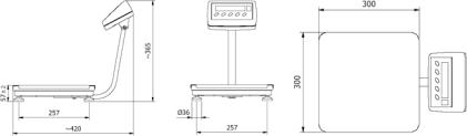
4.4. Scales of WPT series
WPT…C1/K series – main dimensions
- 12 -
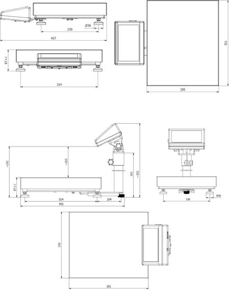
WPT…C1/R series - main dimensions
WPT…C1 series – main dimensions
- 13 -
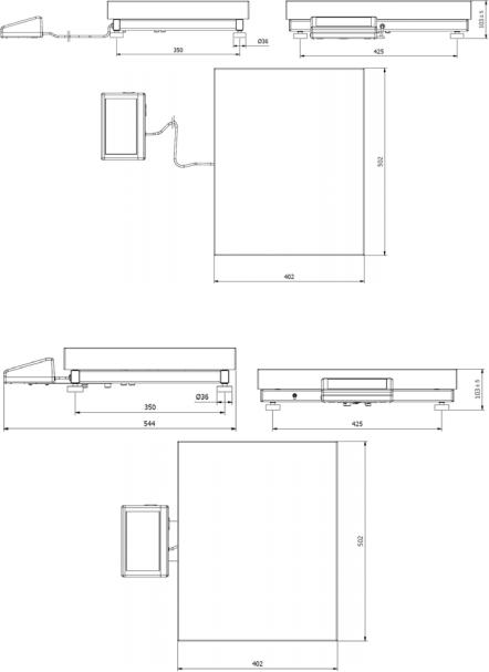
WPT…C2/K series – main dimensions
WPT…C2/R series – main dimensions
- 14 -

WPT…C2 series – main dimensions
WPT…C3/K series – main dimensions
- 15 -

WPT…C3 series – main dimensions
5. UNPACKING AND ASSEMBLY
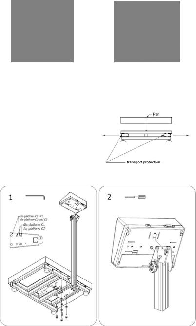
5.1. Table scales of WPT/F series
Unpack and put the scale on a flat even stable surface far away from sources of heat.
•maximally screw out the transport protection according to the drawing below:
•Install the pillar, be careful about the cable linking the indicator with the load cell:
-16 -
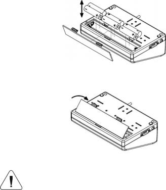
5.2. Scales of WPT series
Unpack and put the scale on a flat even stable surface far away from sources of heat and then:
- Remove transport protection:
For versions with an indicator on the pillar:
- 17 -
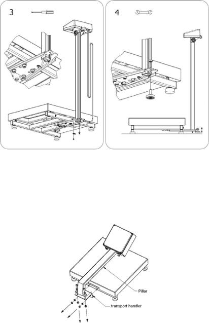
5.3. Waterproof scales of WPT/H, WPT/HR series
Unpack and put the scale on a flat even stable surface far away from sources of heat and then:
• Unscrew the pillar and the transport handler from the platform:
- 18 -
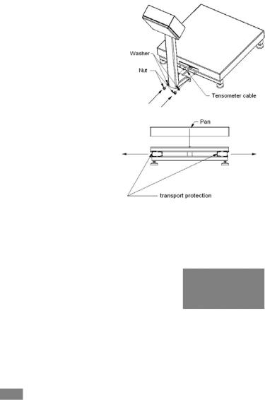
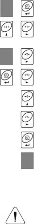
•Turn the pillar and mount it to the platform. The surplus cable place inside the pillar.
•Pick up the pan and remove the transport protection.
6.GETTING STARTED
•After unpacking and mounting the scale level it out. Use levelling legs and the level condition
indicator installed in the basis of the scale.
•Turn the device on using the  key – keep pressing the key for about 0.5 sec,
•Wait for the test completion,
•Then you will see zero indication and pictograms:
- zero indication
 - stable result kg - weight unit
•If the indication is not zero press zero key.
-19 -

7. KEYPAD
8. KEYS’ FUNCTIONS
Switching on/off
Function key (operation mode selection)
Sending a weighing result to RS232
Zeroing
Tarring
Notice:
After pressing  +
+  keys’ functions changes. The way of operation in this mode is described in details further in this manual.
- 20 -
9. INSCRIPTIONS ON THE DISPLAY
No |
Text string |
Description |
|
|
|
|
|
1. |
FIL |
Filter level |
|
|
|
|
|
2. |
bAud |
Transmission baud rate |
|
|
|
|
|
3. |
PCS |
Piece counting |
|
|
|
|
|
4. |
HiLo |
+/- control according to a standard mass |
|
|
|
|
|
5. |
rEPL |
Automatic printout |
|
|
|
|
|
6. |
StAb |
The condition of printing data |
|
|
|
|
|
7. |
Auto |
Autozero correction |
|
|
|
|
|
8. |
t1 |
Power save – time to switch off while no operation |
|
|
|
|
|
9. |
toP |
Latch of the max measurement |
|
|
|
|
|
10. |
Add |
Totalizing |
|
|
|
|
|
11. |
AnLS |
Weighing animals |
|
|
|
|
|
12. |
tArE |
Memory of 9 tare values |
|
|
|
|
|
13. |
|
Indication in autozero zone (indication = exact zero) |
|
|
|
|
|
14. |
|
Stable result (ready to read) |
|
|
|
|
|
15. |
PCS |
Operation mode – counting pieces |
|
|
|
|
|
16. |
kg (g) |
Operation mode – weighing |
|
|
|
|
|
17. |
|
Rechargeable battery pack or battery discharged (BAT-LO) |
|
|
|
|
|
18. |
Net |
Tare function has been used |
|
|
|
|
|
19. |
Min |
+/- control with reference to the standard mass: setting |
|
the lower threshold or mass below the first threshold |
|||
|
|
||
20. |
OK |
+/- control with reference to the standard mass: |
|
load mass between the thresholds |
|||
|
|
||
21. |
Max |
+/- control with reference to the standard mass: setting |
|
the upper threshold or mass over the second threshold |
|||
|
|
- 21 -
10. USER MENU
10.1. Submenus
User’s menu is divided into 6 basic submenus. Each group has its own characteristic name preceded by the letter P and a number.
P1 rEAd |
|
|
|
P 1.1 |
Fil |
| |
2 |
P 1.2 Auto |
| |
YES |
|
P 1.3 |
tArA |
| |
no |
P 1.4 Fnnd |
| |
no |
|
P2 Prnt |
|
|
|
P2.1 |
Pr_n |
| |
StAb |
P2.2 |
S_Lo |
| |
|
P2.3 |
bAud |
| |
9600 |
P2.4 |
S_rS |
| |
8d1SnP |
P3 Unit |
|
|
|
P3.1 |
StUn |
| |
kg |
P4 Func |
|
|
|
P4.1 |
FFun |
| |
ALL |
P4.2 |
Funi |
| |
no |
P4.3 |
PcS |
| |
no |
P4.4 |
HiLo |
| |
no |
P4.5 |
PrcA |
| |
no |
P4.6 |
Prcb |
| |
no |
P4.7 |
AtAr |
| |
no |
P4.8 |
toP |
| |
no |
P4.9 |
Add |
| |
no |
P4.A |
AnLS |
| |
no |
P4.b |
tArE |
| |
no |
P5 othr |
|
|
|
P5.1 |
bL |
| |
Auto |
P5.2 |
bLbt |
| |
70 |
P5.3 |
bEEP |
| |
YES |
P5.4 |
t1 |
| |
Auto |
P5.5 |
CHr6 |
| |
YES |
P6 CAL |
|
|
|
P6.1 |
St_u |
| |
* FUNCTION * |
P6.2 |
uCAL |
| |
* FUNCTION * |
- 22 -
10.2. Browsing user menu
Use scale’s keys to move inside the menu.
10.2.1. Keypad
Entering main menu
+
Inscribing tare value
+Increasing a digit value by „1” moving down in the menu
Battery / accumulator state monitoring
+
Toggling between gross / net values
+
Selecting the parameter or changing the value of a selected parameter
Entering the selected submenu or activating a parameter for changes
Confirmation (enter)
Leaving without changes or reaching a higher level of the menu
10.2.2. Return to the weighing mode
The changes that have been introduced should be saved in order to keep them in the memory for good.
While leaving parameters press  key until the text
<SAuE?> appears on the display. Then press: 
–to save changes or  – to leave without changes.
-23 -
11. WEIGHING
Put a load you want to weigh on the weighing pan. When the  pictogram appears it means that the result is stable and ready to read. In order to assure long-term operation and appropriate measurements of weighted loads following precautions should be taken into consideration:
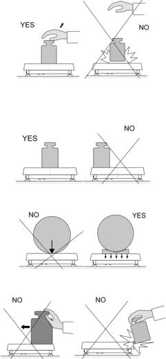
•Loads should be placed on the pan delicately and carefully in order to avoid mechanical shocks:
•Loads should be placed centrally on the pan (errors caused by eccentric weighing are outlined by standard PN-EN 45501 ch. 3.5 and 3.6.2):
•Do not load the pan with concentrated force:
•Avoid side loads, particularly side shocks should be avoided:
- 24 -
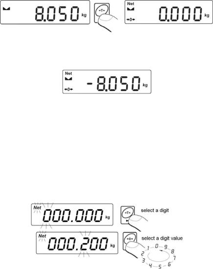
11.1. Tarring
In order to determine the net mass put the packaging on the pan.
After stabilising press -  (Net pictogram will be displayed in the left upper corner and zero will be indicated).
After placing a load on the weight pan net mass will be shown. Tarring is possible within the whole range of the scale. After unloading the pan the display shows the tarred value with minus sign.
Notice:
Tarring cannot be performer when a negative or zero value is being displayed. In such case <Err3> appears on the display and short audible signal will be emitted.
11.2. Inscribing tare value
You can also inscribe a tare value. While in weighings mode press:
•Press simultaneously  and
and  ,
,
•You will see :
- 25 -
•Using  and
and  set the tare value,
•Press  ,
,
•Program returns to weighings mode. The inscribed tare value can be seen on the display with „–” sign,
•Tare can be inscribed anytime in weighings mode.
Notice:
1.You cannot inscribe a new tare value when the tare value in memory is greater than zero. In the case of trying this the <Err3> message will be displayed and short audible signal will be emitted.
2.Users can also enter up to 9 tare values to the scale memory (see 15.10 of his manual).
11.3. Zeroing
To ZERO the scale press:  .
.
The scale will display zero and following pictograms:  and
and  . Zeroing is only possible within the scope of ±2% of full scale. While zeroing outside the scope of ±2% you will see <Err2>. Zeroing is possible only in stable state.
Notice:
Zeroing is possible only within the ±2% interval of the maximal range. If zeroing is performed beyond this range the <Err2> message and short audible signal will be emitted.
11.4. Weighings in two ranges
Switching between the I range and the II range happens automatically (exceeding Max of the I range). Weighings in the second range is signalled by a pictogram in the top left corner of the display.
Then weighings is done with the accuracy of the II range to the moment of returning to zero (autozero range  ) where the scale switches back to the I range.
- 26 -
Loading...