

Page 1
Manual number
PTI-12-03/01/07/A
Integrated system for counting pieces and labelling
WLT/L series
WLL series
MANUFACTURER OF ELECTRONIC WEIGHING INSTRUMENTS
RADWAG, 26 – 600 Radom, Bracka 28 Street
POLAND
phone +48 48 38 48 800, phone/fax. +48 48 385 00 10
Sales Department +48 48 366 80 06
www.radwag.com
Page 2

TABLE OF CONTENTS
1. UNPACKING OF THE MAIN BALANCE.......................................................5
2. INTENDED USE............................................................................................. 6
3. GETTING STARTED......................................................................................7
3.1 Conditions of appropriate use................................................................................7
3.2 Time of warming-up...............................................................................................7
3.3. Balance levelling...................................................................................................8
4. UNDER-FLOOR WEIGHING.......................................................................... 8
5. BALANCE DESCRIPTION............................................................................. 9
5.1. Graphic display.....................................................................................................9
5.2. Balance keyboard...............................................................................................10
5.3. PC keyboard.......................................................................................................11
5.4. Connecting sockets............................................................................................12
6. USER MENU ................................................................................................13
6.1. Menu view..........................................................................................................16
6.2. Menu navigating.................................................................................................17
6.3. Return to weighing..............................................................................................18
7. WEIGHING ................................................................................................... 18
7.1. Tarring................................................................................................................19
7.2. Inscribing tare value ...........................................................................................20
7.3. Automatic tare....................................................................................................20
7.4. Zeroing...............................................................................................................21
8. BALANCE CALIBRATION .......................................................................... 22
9. SETTING OF PRINTOUTS CONTENTS FOR GLP PROCEDURES..........23
10. TIME AND DATE SETTING....................................................................... 23
11. SETTING WORK PARAMETERS.............................................................. 26
11.1. Filter setting......................................................................................................26
11.2. Median filter setting ..........................................................................................26
11.3. Setting the time of display refreshment ............................................................27
11.4. Setting of autozero operating ...........................................................................27
11.5. Last digit...........................................................................................................27
11.6. Negative...........................................................................................................28
11.7. Two platforms...................................................................................................28
11.8. Automatic tare..................................................................................................28
12. FUNCTIONS CONNECTED WITH RS 232 USE.......................................28
13. PRINTOUTS............................................................................................... 29
14. SETTING ACCESSIBILITY OF WEIGHT UNITS ...................................... 30
15. SETTING ACCESSIBILITY OF WORK MODES.......................................31
16. OTHER PARAMETERS............................................................................. 31
2
Page 3

17. COUNTING PIECES...................................................................................34
17.1. Databases........................................................................................................34
17.1.1. Database of operators............................................................................................. 34
17.1.2. Database of labels...................................................................................................35
17.1.3. Assortment database ..............................................................................................41
17.1.4. Contractors database..............................................................................................42
17.2. Settings of operating for counting pieces..........................................................43
17.2.1. Configuration...........................................................................................................43
17.2.2. Printer settings ........................................................................................................ 44
18. COUNTING PIECES...................................................................................45
18.1. Description of graphic display for Counting pieces mode.................................45
18.2. Reference mass setting....................................................................................46
18.2.1. Inserting known mass of single piece .....................................................................46
18.2.2. Determining (weighing) by declared quantity of sample .........................................46
18.2.3. Wprowadzenie masy detalu z bazy danych wagi.................................................... 48
18.3. Introducing reference mass to balance memory...............................................49
18.4. Counting pieces with checkweighing................................................................49
19. LABELLING ...............................................................................................50
19.1. Quick database search.....................................................................................50
19.1.1. Quick assortment database search......................................................................... 50
19.2. Operator selection and logging in.....................................................................51
19.3. Article selection ................................................................................................51
19.4. Contractor selection..........................................................................................51
19.5. Deleting „n1” and n”2” counters and „sums” variable........................................51
20. REGULAR LABELLING ............................................................................ 52
20.1. Cumulative label printing..................................................................................52
20.2. Printing of “cc” label”.........................................................................................54
20.3. Initiating “cc label” by “n2” counter....................................................................54
20.4. Initiating “cc label” by “n2” counter....................................................................55
20.5. Initiating “c label” and “cc label” by determined quantity of pieces ...................56
20.6. Labelling with checkweighing...........................................................................56
20.7. Automatic printout.............................................................................................57
21. BARCODES ...............................................................................................57
21.1. General description ..........................................................................................57
21.2. EAN code.........................................................................................................58
21.3. Other barcodes.................................................................................................58
21.4. Advantages of using barcodes .........................................................................58
21.5 The usage of EAN-128 barcode in scales.........................................................59
21.6. Operating with barcode scanners.....................................................................61
22. STATISTICS...............................................................................................64
3
Page 4

23. PRINTOUTS............................................................................................... 65
23.1. Standard printout..............................................................................................65
23.2. Non-standard printouts.....................................................................................66
23.2.1. Inscribing texts ........................................................................................................69
23.2.2. Choice of non-standard printouts............................................................................ 73
23.2.3. Changing set of characters for EPSON TM-U220 series (Polish characters).......73
24. COOPERATION WITH PRINTER OR WITH COMPUTER........................74
24.1. Drawings of connection cables.........................................................................74
25. COOPERATION WITH COMPUTER PROGRAM „DB editor” ...............75
26. TRANSMISSION POTOCOL ..................................................................... 76
26.1. Some basic information....................................................................................76
26.2. Transmission parameters.................................................................................76
26.3. Transmission characteristics ............................................................................77
26.4. Continuous transmission/automatic printout.....................................................77
26.4.1. Types of printouts.................................................................................................... 77
26.4.2. Continuous transmission.........................................................................................78
26.4.3. Continuous transmission „with pauses”...................................................................78
26.4.4. Stable result transmission.......................................................................................78
26.4.5. Survey of automatic printouts.................................................................................. 79
26.5. Commands and responses syntax...................................................................80
26.5.1. Commands syntax...................................................................................................80
26.5.2. Response syntax..................................................................................................... 81
26.6. List of commands computer - balance..............................................................82
27. ERROR MESSAGES..................................................................................85
28. TECHNICAL PARAMETERS.....................................................................86
28.1. WLT/L series ....................................................................................................86
28.2. WLL series .......................................................................................................87
APPENDIX A....................................................................................................88
APPENDIX B....................................................................................................89
APPENDIX C....................................................................................................89
4
Page 5
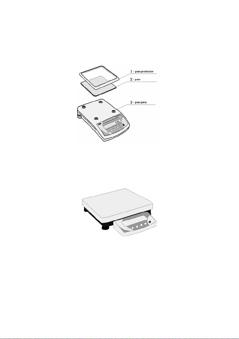
1. UNPACKING OF THE MAIN BALANCE
Cut open tape protecting the box. Take out the balance of factory package and
place it on a stable base. Take out all components and assemble them
according to below drawings:
Fig 1. The components installation for the balance with pan size 165 x 165mm
For balances 300 x 300mm or 410 x 410mm put on the pan and set the scale
working according to the chapter 2 of this manual.
Fig 1-1. The balance with pan size 300 x 300mm
5
Page 6

Fig 1-2. The balance with pan size 410 x 410mm
Balances are supplied from 230 V AC / 11 V AC adapters. Connect to the
power source and turn on the balance.
2. INTENDED USE
Counting – labelling balances are designed for COUNTING PIECES OF THE
SAME MASS. Connection with label printer enables labels printing.
Balances are equipped with data bases of operators, assortments, labels and
contractors. Connected with bar code scanner searching out assortment by bar
code is possible.
6
Page 7

Software of counting set makes possible:
- determining mass of single detail on main balance with highest
accuracy of weighing
- owing to application of graphic display, balance software is user-
friendly
- possibility of application PC type PS/2 keyboard simplifies moving in
software menu and data accessing
- printing basic labels, cumulative labels, „cc labels” (cumulative labels of
cumulative ones)
- cooperation with barcode scanner
- cooperation with additional balance platform
3. GETTING STARTED
3.1 Conditions of appropriate use
9 place balance on a stable and flat table or free from vibrations
9 balance should not be exposed to draughts and sudd en air movements
9 balance should be placed in room of stable temperature and humidity
9 balance should be placed far from heat sources
9 temperature of the room should be +15°C ÷ +30°C (for WLT balances)
9 if static electricity influence balances, indications, its base should be
earthed. Earthling clamp is in the back part of balance base
9 balances should be levelled according to a level condition indicator to
guarantee the appropriate weighing accuracy
3.2 Time of warming-up
Before performing measurements wait until balance reaches temperature
stabilization. It is so-called warm-up time. It takes about 15 minutes.
For weighing instruments that have been stored in low temperatures (e.g.
during winter) the warm-up time is about 2 hours.
The indications of display may change during temperature stabilization.
7
Page 8

3.3. Balance levelling
To do the measurements correctly level the scale. Take the pan off carefully
(without rapid pulls and hits) and turn the legs in order to level the balance, air
bubble should be place in the centre of level condition indicator.
Fig. 2. Balance levelling
1- correct levelling
2- incorrect levelling
4. UNDER-FLOOR WEIGHING
For scales with 165 x 165mm platforms can weigh underslinged loads (hanged
under the balance floor). In case of using this function:
− remove the hole plug made of plastic (placed in the balance floor),
− a suspension can be seen in the hole. It is standard equipment,
− Mount an appropriate hook for hanging loads (hook is non-standard
equipment).
1. The suspense cannot be rotated, revolved or tampered in any way,
because of direct connection with the weighing mechanism of the
balance.
2. All the additional elements like pan, string etc. should be tarred (TARE).
3. Balances with 300 x 300mm or 410 x 410mm platforms do not have the
under-floor weighing mechanism.
8
Page 9
5. BALANCE DESCRIPTION
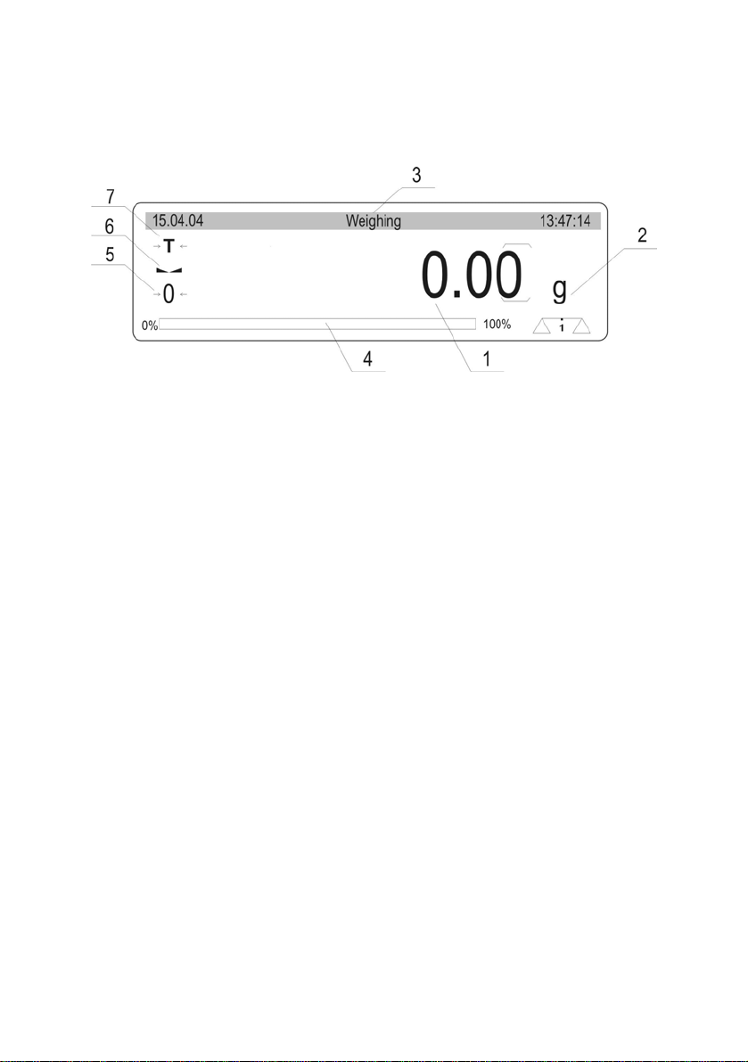
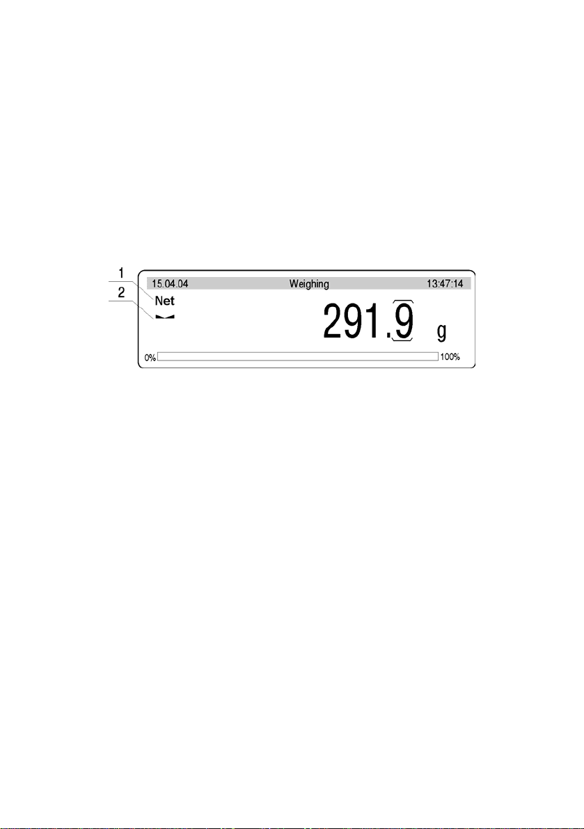
5.1. Graphic display
Fig. 3. Graphic display
1. displayed mass of currently weighed load
2. unit of mass
3. upper „bargraph” in which description of operating mode, date and time of
internal balance clock are displayed
4. lower „bargraph” in which part of mass from range of max capacity used
currently is displayed
5. symbol of precise zero
6. symbol indicating stable weighing result
7. symbol indicating weighing with tare
9
Page 10
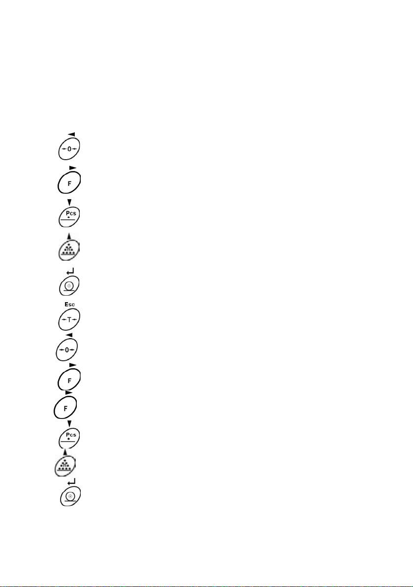
5.2. Balance keyboard
Each key on balance keyboard is dual-function key, its function depends on
balance operating mode.
Balance
keyboard
Function in weighing mode
zeroing zeroing
Enter to balance menu Enter to counting pieces menu
Function in Counting pieces
mode
Enter to choice of operating mode
Change of weighing unit
Sending display state to external
device (PRINT)
Balance tarring Balance tarring
+
Introducing Id codes
+
Introducing mass of single pcs
+
Change of weighing platform Change of weighing platform
Enter to choice of operating
mode
Determining mass of single
detail by weighing
Label printout
10
Page 11

5.3. PC keyboard
PC keyboard is necessary for correct balance operating (moving in balance
menu). Without PC keyboard access to some functions is impossible, above
that database edition is more convenient and efficient by using PC keyboard.
PC
keyboard
F1
Function in weighing
mode
Indication zeroing Indication zeroing
Function in Counting pieces mode
F2
F3
F4
F5
F6
F7
F8
F9
F10
F11
INSERT
HOME
PAGE UP
Enter to balance menu Enter to counting pieces menu
Enter to choice of
operating mode
Change of weighing unit Determining mass of single detail by
Sending display state to
external device (PRINT)
Balance tarring Balance tarring
- Operators base – choice of operator
- Assortments base – choice of assortment
- Contractors base – choice of contractor
- Cumulative printout with counters deleting
- Printout of “cc” label with counters deleting
- Setting N1, N2 counters, V1, V2 any text,
- Printout of cumulative label without counter
Id codes edition Id codes edition
Enter to choice of operating mode
weighing
Label printout
M1, M2 sums of details quantity and
starting point of counter n1
deleting
END
PAGE
DOWN
- Printout of “cc” label without counters
deleting
- Introducing mass of single detail
11
Page 12

DEL
- Deleting counters and statistics
TAB
ESC
Change of weighing
platform
Resignation from
introduced changes
5.4. Connecting sockets
1. Adaptor socket (11V AC 50Hz)
2. PC keyboard socket
3. RS 232 socket
4. additional display socket
5. earthling screw
6. RS 485 socket
7. main switch
Change of weighing platform
Resignation from introduced changes
Fig. 4. Sockets
12
Page 13

6. USER MENU
User’s menu comprises 9 groups of parameters signed by P. Below you can
see listed groups and parameters.
P1 Calibration
P2 GLP
P3 Date/Time
P4 Reading
01 Ext. calibration |
02 User calibration |
03 Report printout | * * * * * *0.1 | on
01 User | No wak Jan |
02 Project | AR – 65/04 |
03 Time printout | * * * * * *0.0 | off
04 Date printout | * * * * * *0.0 | off
05 User printout | * * * * * *0.0 | off
06 Proj. printout | * * * * * *0.0 | off
07 Id printout | * * * * * *0.0 | off
08 Calibr. printout | * * * * * *0.0 | off
* * * * * * * *
* * * * * * * *
01 Date format | * * * * * * * 0 | DA/MO/YR
02 Time format | * * * * * * * 0 | 24 hours
03 Time |
04 Date |
05 Display time | * * * * * * * 1 | on
06 Display date | * * * * * * * 1 | on
01 Filter | * * * * * * * 3 | average
02 II - / - / - / - | * * * * * * * 3 | average
03 Median filter | * * * * * * * 3 | average
04 II - / - / - / - | * * * * * * * 3 | average
05 Refreshing | 0 | 0,04s
06 Autozero | * * * * * * * 1 | on
07 II - / - / - / - | * * * * * * * 1 | on
08 Last digit | * * * * * * * 1 | always
09 II - / - / - / - | * * * * * * * 1 | always
10 Negative. | * * * * * * * 0 | off
11 Both platforms | 0 | off
12 Aut. tare | 0 | off
* * * * * * * *
* * * * * * * *
| function
| function
| function
| function
13
Page 14

P5 RS - 232
P6 Printouts
P7 Units
01 Trans. speed | * * * * * * * 1 | 4800
02 Parity | * * * * * * * 0 | non e
03 Data bits | * * * * * * * 2 | 8 bits
04 Stop bits | * * * * * * * 1 | 1 bit
05 Trans. control | * * * * * * * 0 | none
06 Aut. printout | * * * * * * * 0 | none
07 Interval | * * * * * * * 1 | * 0.1 s
08 Min. mass | * * * * * * * 4 | 10 d
09 Print stab | * * * * * * * 1 | on
10 Pause | 1 | *0,1s
11 Printer type | 1 | CitizenCLP
01 Prn. memory | * * *
02 Prn. destination |* * * * * * * 0 | RS
03 Printout no. | * * * * * * * 0 | standard
04 Print. 1 start | * * * * * * * 1 |
05 Print. 1 stop | * * * * * * * 1 |
06 Print. 2 start | * * * * * * * 1 |
07 Print. 2 stop | * * * * * * * 1 |
... . . . . . . . . . . | * * * * * * * 0 |
12 Text 1 | * * * * * * * 1 |
13 Text 2 | * * * * * * * 4 |
... . . . . . . . . . . | * * * * * * * 1 |
92 Tekst 80 | * * * * * * * 0 |
* * * * * | function
01 Grams | * * * * * * * 1 | on
02 Kilograms | * * * * * * * 1 | on
03 Pounds | * * * * * * * 0 | off
04 Ounces | * * * * * * * 0 | off
05 Ounces troy | * * * * * * * 0 | off
06 Carats | * * * * * * * 0 | off
07 Dwt | * * * * * * * 0 | off
08 Taele Hk. | * * * * * * * 0 | off
09 Taele S. | * * * * * * * 0 | off
10 Taele T. | * * * * * * * 0 | off
11 Mommes | * * * * * * * 0 | off
12 Grains | 0 | off
13 Newton | 0 | off
14 Tical | 0 | off
15 Custom | 0 | off
16 User Factor | 1.0 |
14
Page 15

P8 Operating modes
01 Counting pieces | * * * * * * * 1 | on
02 Statistic | 1 | on
03 Starting mode | 1 | counting
P9 Other
01 Address | 1 |
02 ID setting | * * *
03 ID autoprinting | 0| off
04 Signal | * * * * * * *1 | on
05 Language | * * *
06 Backlight | * * * * * *
07 Contrast |
08 Screensaver | * * * * * *
09 Balance number | 1144 93 *
10 Software number | MCB e.08 * |
11 Par. printout |
12 Par. receive |
13 Password | 0 |
14 Bar code reader | * * *
Parameters in user menu can be:
* * * * * | function
* * * * * | function
1 | on
* * * * * * * *
* * * * * * * *
* * * * * * * *
* * * * * | function
| function
* 0 | off
* * |
| function
| function
• functional – for particular activities e.g. balance calibration
• selectable – enable choice one of few values which are permanently
declared in balance memory e.g. refreshing, display screensaver,
declaring measuring units, declaring functions
• introduced – enabling change of some of setting saved in balance
memory e.g. date, time, user number, texts
15
Page 16
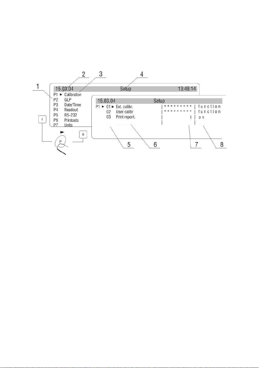
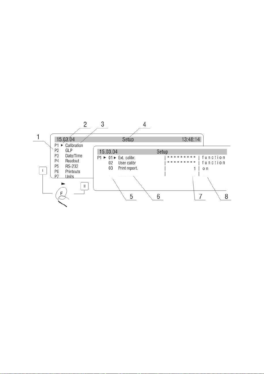
6.1. Menu view
While in weighing press F key, display shows main balance menu (display I).
Moving by marker up or down, set it next to submenu which contents you want
to see. Press → key, display will show contents of submenu (display II)
Fig. 5 View of balance menu
1 – number of main menu
2 – choice of function marker
3 – name of function
4 – name of currently performed activity
5 – number of submenu
6 – name of submenu
7 – attribute of submenu
8 – value referring to attribute
16
Page 17
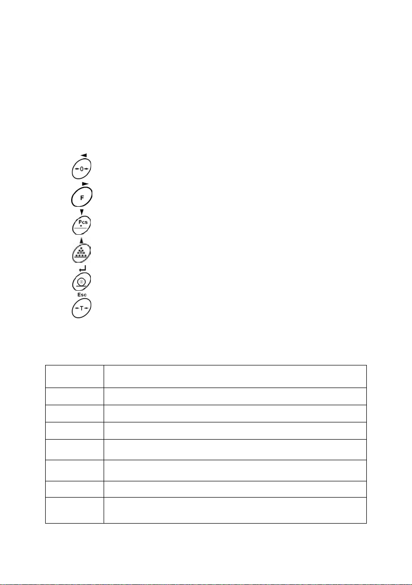
6.2. Menu navigating
Moving in user menu is possible by means of balance keyboard or attached PC
keyboard.
By means of balance keyboard
Balance keyboard Description
By means of PC keyboard
Key Description
F2
ESC
ENTER
↓
Exit to one step higher level to menu
Enter to parameter edition
Moving marker downwards
Moving marker upwards
Confirmation of introduced value
Cancellation of changes, exit from menu
Enter to balance menu
Cancellation of changes, exit from submenu
Confirmation of introduced value
Moving cursor downwards menu
↑
→
←
Moving cursor upwards menu
Enter to submenu, parameter edition
Exit to one step higher level e.g. from submenu to main
menu
17
Page 18
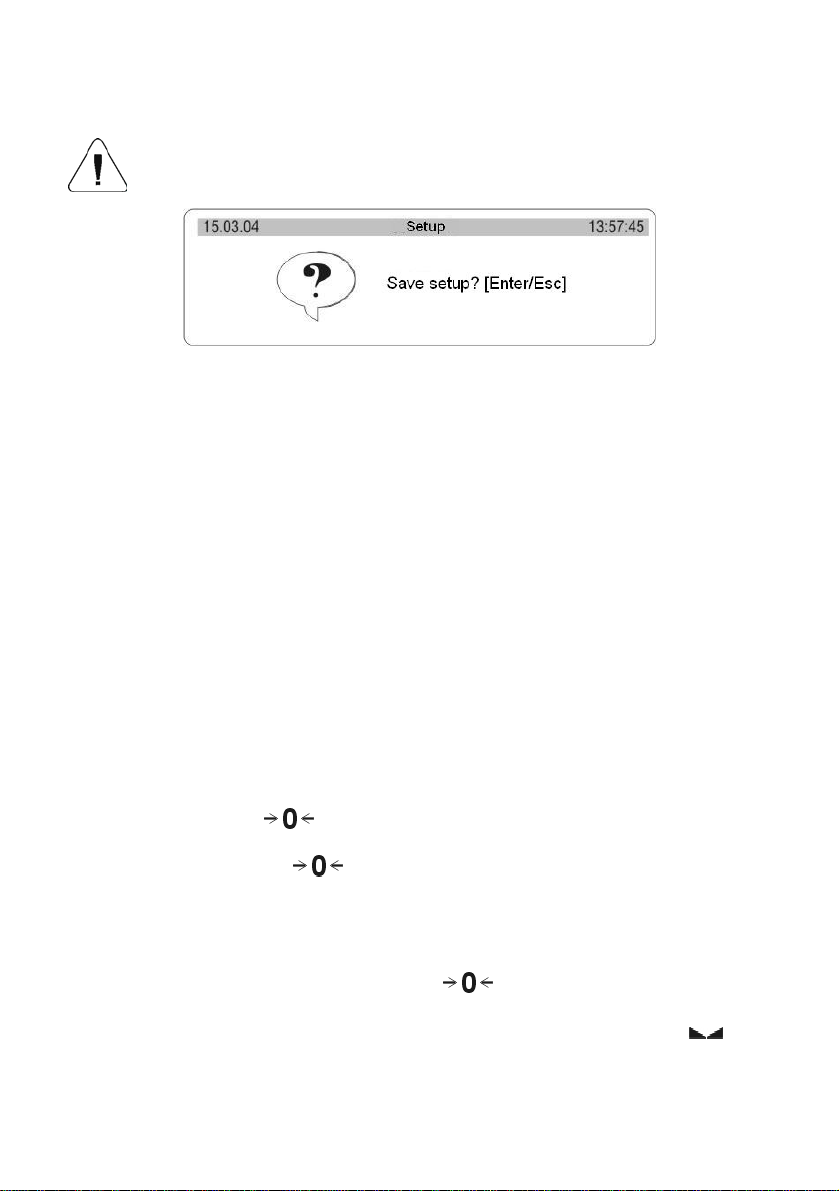
6.3. Return to weighing
Introduced changes in settings will be saved after return to weighing
mode with procedure of saving changes.
Fig. 6. Return to weighing
After introducing all changes in parameters settings press several times ESC
key. When display indicates message, choose one of two options:
ENTER – save changes
ESC – without saving
7. WEIGHING
Basic conditions which should be fulfilled to ensure reliability of measurements:
9 stable base for balance,
9 choice of appropriate parameters for existing external conditions
Before measurements or in case of essential changes of external conditions,
balance should be calibrated according to manual (for verified balances,
function of calibration is not accessible for user)
Before measurements check if unloaded balance indicates „precise zero” –
indicated pictogram -
parameter is set on 1: yes or P4 07 for second platform), if balance doesn’t
indicates zero press key:
If conditions for zeroing are unfavourable (lack of stable result), display
indicates horizontal lines. After exceeding set zeroing time of balance will
return to weighing without performing zeroing. In such case wait for
stabilization of conditions and press again
Place on the pan weighed load and when results are stable (indicated
read on the display result of weighing.
- in left lower corner (only when P4 06 Autozero
.
key.
)
18
Page 19
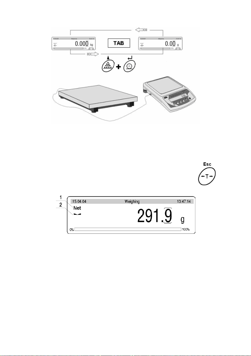
Fig. 7. Weighing- choice of weighing platform
TAB- by means of PC keyboard11
PRINT+n – by means of balance keyboard
7.1. Tarring
For determining net mass place on the pan package
of load and when indication is stable press T key.
Fig. 7a. Tarring – display view
1 –TARE signature (NET is being displayed)
2 –stable result signature
Tarring can be performed repeatedly in the whole balance weighing range.
Using tare function pay attention not to exceed the maximum weighing range.
After removing the load and package display will indicate mass equal to mass
of tare with minus sign.
Notice:
Tare value is not stored in balance memory and is deleted after disconnecting
from mains
19
Page 20
7.2. Inscribing tare value
It is possible to inscribe tare value.
To do it in weighing mode follow the below instructions:
• Select the platform for tarring,
• Using PC keyboard inscribe a tare value (in basic unit) according to
display format e.g.: if the basic unit is “kg” and 0,005kg is a scale division
and you want to inscribe 1.05kg as a tare value, enter it in the following
format: 1.050,
• In the bottom left corner the editing field appears for inscribing a tare
value,
Fig. 7b. Inscribing tare – display view
1 – tare designator
2 – stability designator
3 – tare value
• press T or F6 (PC keyboard),
• Tare can be inscribed any time.
Notice
Use “point” for decimal fractions.
7.3. Automatic tare
This function is useful for quick determining net mass of weighed goods when
tare values are different for each weighings. It is accessible in <P4 Readout>
parameters group.
20
Page 21
Enabling function:
Fig. 7c. Automatic tare – enabling
After setting an appropriate value of the parameter return to weighing 5.3. of
this manual.
The way of operation:
• Press ZERO button when the pan is empty,
• Put a package on the pan,
• After stabilizing tarring is performed (Net designator is displayed in the
top left corner of the display),
• Put an article on the pan,
• The display shows the net mass of the article,
• Unload the pan,
• Indication returns to zero,
• Put the next package … and the cycle repeats.
7.4. Zeroing
For zeroing display indication press
to zero and display will indicate a graphic signature in left lower
corner
.
Zeroing of indication is possible only in range of 2% of maximum capacity
currently displayed balance/platform. If zeroed value is bigger than 2% of
maximum capacity display will indicate error message and return to displaying
previous value – for main balance or displayed mass will not change.
key. Indication will return
21
Page 22
Notice:
Balance zeroing determines a new zero point treated by balance as precise
zero. Zeroing is possible only in stable states of the indication.
8. BALANCE CALIBRATION
To ensure very high accuracy of weighing, periodical entering to memory
correction factor of balance indication referring to standard mass is required; it
is so called balance calibration. In WLT balances it is inaccessible for user. The
procedure of calibration can be performed only by authorized services of the
manufacturer.
Fig. 8. Internal setting of calibration
1 – main menu number
2 – cursor
3 – group of parameters
4 – status bar
5 – parameter number
6 – parameter name
7 – parameter value
8 – parameter description
Notice:
In verified scales calibration can be accessed from the user’s menu. Calibration
should be performed with no load on the pan!
22
Page 23
9. SETTING OF PRINTOUTS CONTENTS FOR GLP PROCEDURES
P2 GLP his group of parameters allows to enable/disable printing some
variables on the standard printout and calibration report.
For variables:
User and project name (max 8 alphanumerical characters) enter names with
balance keyboard or with PS/2 keyboard.
For remaining fields, select digits:
- 0 no (do not print during report)
- 1 yes (print during report)
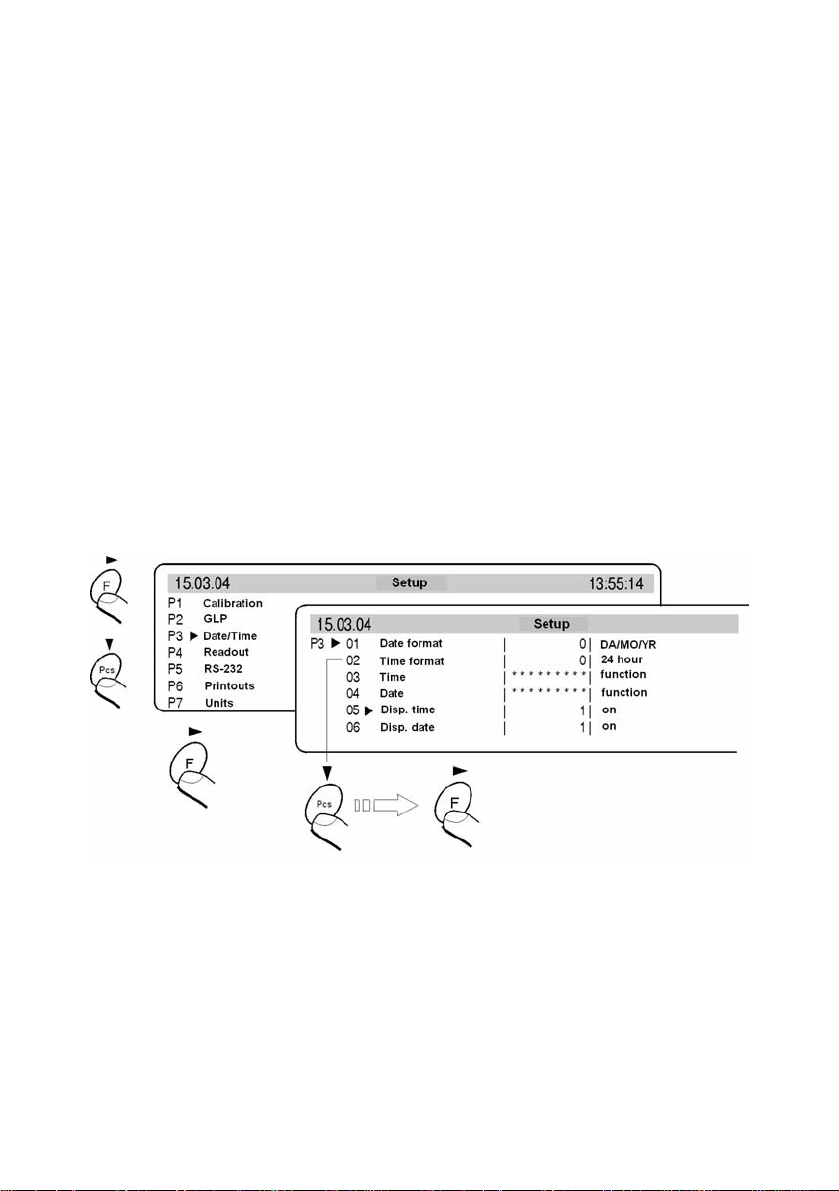
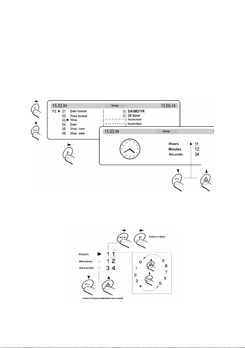
10. TIME AND DATE SETTING
Balances have a real time clock, which can be modified. Enter menu group P3
Date/Time according to the below scheme:
Fig. 9. Date/Time submenu
01 Date format
has doublestate choice according to below dependance
- 1 date format Month/Day/Year
- 0 date format Day/Month/Year
After choice of appropriate value confirm with ENTER key.
23
Page 24
02 Time format
has doublestate choice according to below dependance:
- 1 time format 12 hours
- 0 time format 24 hours
After choice of appropriate value confirm with ENTER key.
Format 12 hours. Is diffrentiated by placing letters PM or AM on printouts.
03 Time
With F key enter parameter 03 Time setting according to below scheme.
Fig. 10. Submenu Date / Time – time setting
Set cursor next to value which os to be changed (Hour, Minute, Second).
Confirm choice pressing F key. Using keys Pcs and n change values.
Fig. 11. Submenu Date / Time – time setting – steering keys
24
Page 25
Confirm set value (last changed digit will stop pulsing)
Above activities repeat for next values. After setting new values of time press
ENTER key. Balance will return to submenu P3 Date/Time and hour displayed
on upper bargraph will change.
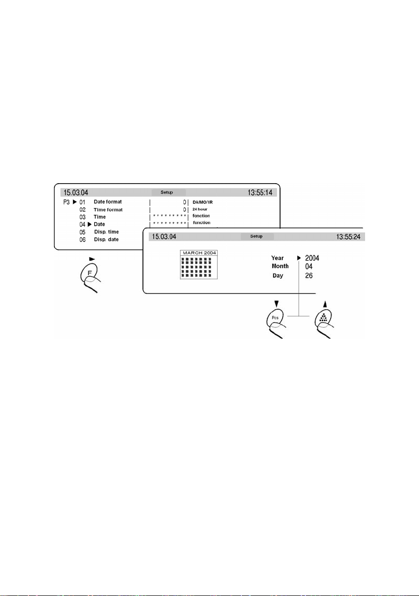
04 Date
With F key enter parameter 04 Date setting.. According to previous description
(03 Time) set current date. After date setting return to weighing mode with
changes saving in menu.
Fig. 12. Submenu Date / Time – date setting
05 Disp time
For setting 1 – YES on upper bargraph, time will be displayed, for setting 0-NO
time will not be displayed.
05 Disp date
For setting 1 – YES on upper bargraph, date will be displayed, for setting 0 –
NO date will not be displayed.
25
Page 26
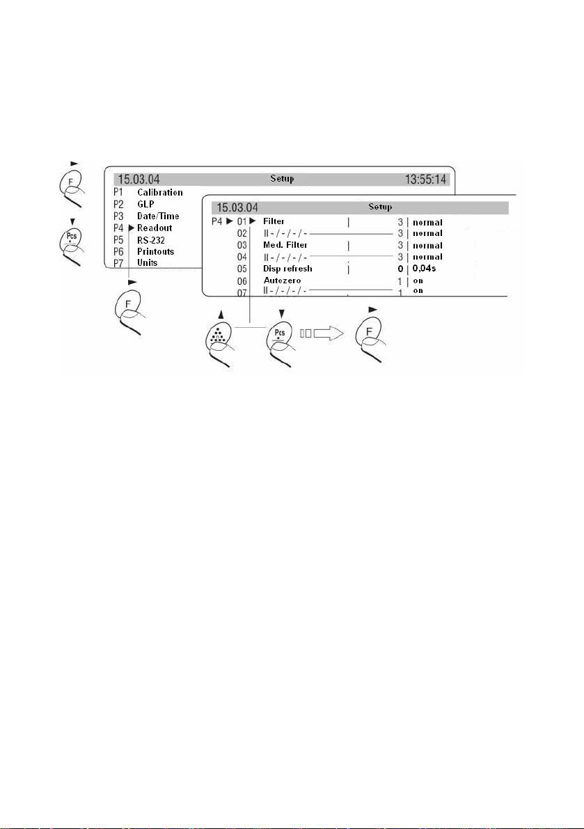
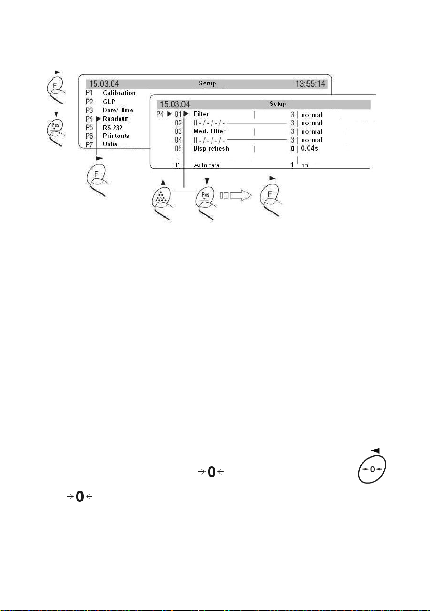
11. SETTING WORK PARAMETERS
User by means of appropriate setting of parameters from menu group <P4
Readout> can adjust the balance to existing operating conditions (filter) and
one’s expectations (refreshing, autozero, last digit displaying)
Fig. 13. Submenu Readout – internal settings
11.1. Filter setting
For perfect conditions filter can be set as very fast, however if conditions are
bad (vibrations, draughts) filter should be set as slow or as very slow.
Effectiveness of filter operating is different for weighing range. Filter works
slower in time of “reaching” the final result, however stronger when mass gets
to set range of filter operating (parameter range of filter operating available only
in service menu – user do not have access to it).
11.2. Median filter setting
Task of median filter is to eliminate single big disturbances. By setting digital
value determines speed of filter operating. For zero option filter operating is off.
26
Page 27

11.3. Setting the time of display refreshment
This parameter determines how often indication of display is refreshed. It is
realized by comparing what in given moment is on the display with information
sent by balance processor about state of weighed mass placed on the pan.
For higher refreshment parameters value display do not indicate intermediate
unstable mass indication by placing and removing the load on balance pan,
however for low values all changes of mass during weighing are visible – e.g.
this enables dosing loose or liquid materials. Time of refreshment is set in
seconds.
11.4. Setting of autozero operating
To ensure accurate balance indications software “AUTOZERO” function was
introduced. Task of this function is automatic control and correction of balance
zero indication.
When function is active comparison of successive results takes place in
declared distance of time e.g. every 1 s. If these result differ in value lower than
declared range of AUTOZERO e.g. 1 interval, balance will automatically zero
and markers of stable result –
and zero indication – will be
displayed.
When AUTOZERO function is on every measurement starts from precise zero.
There are some special cases when this function interrupts in measurem ents.
Example of it can be very slow placing the load on the pan (e.g. pouring the
load) in such case system of zero indication correction can also correct
indication of real mass of load. AUTOZERO can be switch on or off in
parameter P4 06 – main platform 07 – additional platform.
11.5. Last digit
To ensure appropriate comfort of operating with balance user determines
(depending on needs) if last digit of mass indication is to be displayed and in
which states of balance. One of below values can be set:
- 0 never
- 1 always
- 2 when stab
For verified balance option 1 – always is set (without possibility of changing)
27
Page 28

11.6. Negative
Possibility to change displaying mode – negative effect (dark background, light
signs).
11.7. Two platforms
Setting the parameter to YES causes displaying on the display results of
weighing from both platforms at the same time.
11.8. Automatic tare
This function is useful for quick determining net mass of weighed goods when
tare values are different for each weighings (see chapter 7.3. of this manual).
12. FUNCTIONS CONNECTED WITH RS 232 USE
User can set parameters needed for correct communication of balance with
computer or printer.
Fig. 14. Submenu RS 232 – setting
28
Page 29

No and name
parameters
01 Speed of
transmission
02 Parity
03 Data bits
04 Stop bits
05 Transmission
control
Value of
parameters
0 : 2400;
1 : 4800;
2 : 9600;
3 : 19200
0 : none;
1 : par;
2 : odd
1 : 7 bits;
2 : 8 bits
1 : 1 bit;
2 : 2 bits
0 : none;
1 : RTS/CTS;
2 : XON/XOFF
No and name
parameters
07 Interval
08 Min mass Give value
09 Print stab
10 Gap
Value of
parameters
Interval determines
stroke (how often)
balance sends
through RS232 joint
display indication. It
is determined
according to formula
value of parameter x
0.04 s = time of
strokeinterval.Values from
1 to 9999 can be
introduced
0 : no;
1 : yes
Determines gaps
between successive
variables sent
through RS 232 joint
06 Automatic
printout
0 : none;
1 : continuous;
2 : with gaps
3 : by stab
11 Printer type
0 : receipt(EPSON)
1 : Citizen CLP
2 : Zebra
After setting appropriate parameters return to weighing mode with saving
changes.
13. PRINTOUTS
This function is used to configure standard and non-standard printouts. (see
chapter 23).
29
Page 30

14. SETTING ACCESSIBILITY OF WEIGHT UNITS
In this group of parameters user declares measure units which are accessible
for operators directly after pressing the key
.
All units which value of the parameters is set up at 1: yes are accessible from
the level of toggling between units.
For units described as 09 Taele Hk., 10 Taele S., 11 Taele T. there are
following relations:
• If all of them have attribute 1: yes the balance sh ow only first of them
09 Taele Hk
• If the measurement is done in units 11 Taele T set the attribute 0 : no
for two previous
Enter group of the parameters P7 Units according to the figure below.
Fig. 15. Units of measure - setting
NOTICE:
For verified scales (DRH enabled) users can weigh in grams or in kilograms.
Pressing the Units key do not effect changing the unit although they are set to
YES in parameters.
30
Page 31

15. SETTING ACCESSIBILITY OF WORK MODES
In P8 parameters group users can declare work modes that are accessible
directly under the Mode key during operation.
Fig. 16. Work modes - setting
Every operation mode can be enabled/disabled separately.
16. OTHER PARAMETERS.
Users can set parameters influence the operation of the balance in group of the
parameters P9 Others e.g. beep signals etc
01 Address
(not active)
02 ID Setting
it includes 6 digits 6 codes which can be used during printouts for product
specification, operator, batch etc.
03 ID autoprint
for the option YES all digital codes are printed, for option NO the codes
are not printed.
31
Page 32

04 Beep
beep sound for pressing keys
05 Language
selection of languages
According to software versions (last letter in software version „e” or „w”)
following languages are accessible:
(e) language versions (w) language versions
Polish Polish
English English
Czech Italian
German German
Dutch Dutch
Russian French
06 Backlight
switch on/off the backlight
07 Contrast
changes contrast – after entering this function a window appears, by
means of keys on the balance the contrast on the display can be changed
08 Screen server
if the screen server is enabled displayed values disappear after settled
time and if measurement does not change.
09 Balance Id
the information about factory number of the balance
10 Software rev.
information about software version of the balance
11 Par. printout
if the function is active the balance parameters are printed. User can set
numbers of the parameters which should be printed.
32
Page 33

Fig. 17 Submenu others - printing settings
After a confirmation, parameters are printed via RS 232 port.
12 Reception parameters
If the functions are activated all parameters of the balance are received
through RS 232. After reception the balance informs user how many
parameters are accepted, how many are changed, how many were
declared incorrectly and how many were not accepted by the software.
Printing and reception of the parameters is very easy and fast procedure of
introducing new setting. After printing actual parameters to file in the
computer user changes the parameters very fast and without any
problems. User sends new corrected setting to the balance software. After
these changes the balance accepts new set up. User must know all
parameters and computer operation very well.
13 Password
Entering a password results in the necessity of inscribing it whenever you
will try to enter the menu using F or F2 (PC keyboard)
14 Barcode scanner
Settings for barcodes used for the assortment database searching and
variables for labelling.
33
Page 34

17. COUNTING PIECES
17.1. Databases
17.1.1. Database of operators
While in Counting pieces mode press F key on the balance keyboard or F2 on
the PC keyboard.
Choice of operator is done by arrows up and down, enter to edition by arrow to
the right fig.18.
Fig.18. Screen operators base – choice of operator for edition
1 – number of operator
After enter to edition of operator a following window will open:
Fig.19. Screen operators base – edition of operator parameters
name Name of operator (28 signs)
index 4 digits
Id 6 signs
password Password for logging (6 digits)
authorization Authorization level of operator(1 to 5). Level 5 highest authorization
Change of any parameter is performed by pressing arrow to the right and next
using keyboard introduce appropriate value. Confirm changes by ENTER or
cancel them by ESC. Exit from edition (ESC key). Enter to one level of menu
higher (again ESC key).
2 – name of operator
34
Page 35

17.1.2. Database of labels
While in Counting pieces mode press F key on the balance keyboard or F2 on
PC keyboard.
After pressing arrow to the right list of defined labels will open. Choice of label
can be done by arrows up and down, however enter to edition arrow to the right
- fig.20.
Fig.20. Database of labels
1 – number of label
2 – name of label
name Name of label (28 signs)
index 4 digits
6 signs. This name must be the same as name of label design
Id
fields Submenu to choose variables to place on printout (on label)
C39/E128
saved in printer memory. Label design is made in “LABELS”
software attached to CITIZEN CLP printer equipment.
Submenu to choose variables, which are to be introduced as
bar code in code39/ EAN128 format
After choice of submenu “fields” (arrow to the right) following screen will open
fig.21.
Fig.21. Choice of variable to print
35
Page 36

In the field „Selection” you can find.
Operator Name of operator
Operator Id Identity number of operator
Product name Name of operator
Product IDt Id code of assortment
Product EAN Code assigned to particular assortment
Contractor name Name of contractor from contractors base
Contractor ID Code of contractor Id from contractors base
Country Contractors country
City Contractors city
ZIP Contractors postal code
Street Contractors street
TIN Contractors Tax Identification Number
Label NB Counter „n1”
c label NB Number of cumulative label counter„n2”
Pcs. Quantity of pieces
C pcs Quantity of pieces on cumulative label
cc pcs Quantity of pieces on “cc” label
Pcs mass Mass of single piece
Tare Tare
Gross Gross mass
Price price
VAT Value Addend Tax
Value Value of calculated pcs (quantity x price of piece)
c value Value of calculated pcs on cumulative label
cc value Value of calculated pcs on “cc” label
EAN13 pcs.
EAN13+ pcs.
EAN13 value Introduction of particular assortment Id (first 6 signs + control sum) with value
EAN13+ value
Date Current date
Time Current time
Date+ Constant defined date (in Operating setting)
Date+A Constant date assigned to assortment
Date+V Defined date + movement e.g. validity term
Valid Validity term
Introduction of particular assortment Id (first 6 signs + control sum) with quantity
of pcs
Introduction of particular assortment Id 7 signs (extended code for
supermarkets) with quantity of pcs
Introduction of particular assortment Id 7 signs (extended code for
supermarkets) with value
36
Page 37

V1
V2 as V1
V3 As V1
V4 As V1
ID1
ID2 As code1
ID3 As code 1
ID4 As code 1
ID5 As code 1
ID6 as code 1
Printout1 Variables to print defined in submenu “Printouts” P6 in mode “Weighing”
Printout2 Variables to print defined in submenu “Printouts” P6 in mode “Weighing”
Printout3 Variables to print defined in submenu “Printouts” P6 in mode “Weighing”
Printout4 Variables to print defined in submenu “Printouts” P6 in mode “Weighing”
CR,LF Inserting empty line in printout
Code buf. 1 Bar code read by scanner determined by parameters “Start 1” “Length 1”
Code buf. 2 Bar code read by scanner determined by parameters “Start 2” “Length 2”
AI 1 Application identifier (6 characters) defined in submenu M1 06 10 „AI defining”
AI 2 As AI 1
AI 3 As AI 1
AI 4 As AI 1
AI 5 As AI 1
AI 6 As AI 1
Net E128 Net mass for EAN128
Net c. E128 Net mass of cumulative label for EAN128
Net cc. E128 Net mass of cc label for EAN128
Net [lb] E128 Net mass (lb) for EAN128
Gross E128 Gross mass for EAN128
Price E128 Price for EAN128
Date E128 Present date for EAN128
Date+ E128 Constant date for EAN128
Date+A E128 Produkt date (in the assortment database) for EAN128
Date+V E128 Present date + number of validity days for EAN128
Code39/Ean128 Chosen variables presented in bar code
Field to place any text designed for printout on label (numbers, digits).
Edition – Insert key
Constant code (defined by user) Page Up list of six codes„ID”.
Code edition like base edition
37
Page 38

Window “Printout”
In this window list of chosen variables to print will open. Choice of variable is
done by arrows up and down in “variable to choose” window, while confirmation
(transfer to “printout” window) arrow to the right. Monitoring (rewinding the
variables in “printout” window is perform by keys Home (up) and End (down).
Deleting variables from the “printout” window is done by arrow to the left. The
variable which is directly above the cursor is deleted.
Method of assigning variables from “printout” field to fields edited on label
sample is as follows:
Variable from “printout” window with 01 number will be printed on label in first
field (first field on label sample do not have to have 01 number, order of fields
can be determined in PC software. Variable with 02 number will be printed in
next field (according to order in “order of objects” window of “Labels” software).
Next variables similarly to description above.
After choice of submenu „C39/E128” (arrow to the right) screen as on drawing
22 occurs.
Fig.22. Choice of variable to be printed on bar code C39/E128
38
Page 39

Operator Name of operator
Operator Id Identity number of operator
Product name Name of assortment
Product ID Code of assortment
Product EAN Code assigned to particular assortment
Contractor name Name of contractor from contractors base
Contractor ID Code of contractor Id from contractors base
Country Contractors country
City Contractors city
ZIP Contractors postal code
Street Contractors street
TIN Contractors tax identification number
Labels Nb Counter „n1”
c label Nb Number of cumulative label counter „n2”
Pcs Quantity of pieces
C pcs Quantity of pieces on cumulative label
Cc pcs quantity of pieces on „cc”
Pcs. Mass Mass of single piece
Tare Tare
Gross Gross mass
Price Price
VAT Value Addend Tax
Value Value of calculated pcs (quantity x price of piece)
C value Value of calculated pcs on cumulative label
cc value Value of calculated pcs on “cc” label
EAN13 pcs
EAN13+ pcs
EAN13 value
EAN13+ value
Date Current date
Time Current time
Date+ Constant defined date
Date+A Constant date assigned to assortment
Date+V Defined date + movement e.g. validity term
Valid Validity term
V1
V2 As V1
V3 As V1
Introduction of particular assortment Id (first 6 signs + control sum) with
quantity of pcs
Introduction of particular assortment Id 7 signs (extended code for
supermarkets) with quantity of pcs
Introduction of particular assortment Id (first 6 signs + control sum) with
value
Introduction of particular assortment Id 7 signs (extended code for
supermarkets) with value
Field to place any text designed for printout on label (numbers, digits)
Edition – Insert key
39
Page 40

V4 As V1
ID1
ID2 As code 1
ID3 As code 1
ID4 As code 1
ID5 As code 1
ID6 As code 1
Printout1 Variables to print defined in submenu “Printouts” P6 in mode “Weighing”
Printout2 Variables to print defined in submenu “Printouts” P6 in mode “Weighing”
Printout3 Variables to print defined in submenu “Printouts” P6 in mode “Weighing”
Printout4 Variables to print defined in submenu “Printouts” P6 in mode “Weighing””
CR,LF
Code buf. 1 Bar code read by scanner determined by parameters “Start 1” “Length 1”
Code buf. 2 Bar code read by scanner determined by parameters “Start 2” “Length 2”
AI 1
AI 2 As AI 1
AI 3 As AI 1
AI 4 As AI 1
AI 5 As AI 1
AI 6 As AI 1
Net E128 Net mass for EAN128
Net c. E128 Net mass of cumulative label for EAN128
Net cc. E128 Net mass of cc label for EAN128
Net [lb] E128 Net mass (lb) for EAN128
Gross E128 Gross mass for EAN128
Price E128 Price for EAN128
Date E128 Present date for EAN128
Date+ E128 Constant date for EAN128
Date+A E128 Produkt date (in the assortment database) for EAN128
Date+V E128 Present date + number of validity days for EAN128
Constant code (defined by user). In weighing mode press Page Up list of six
“ID” codes will occur Codes edition similar to base edition
Application identifier (6 characters) defined in submenu M1 06 10 „AI
defining”
Notice:
Edition of labels designs in “Labels” software and method of their recording to
memory of CITIZEN CLP and ZEBRA printer are described in software
instruction manual.
40
Page 41

17.1.3. Assortment database
While in Counting pieces mode press F key on balance keyboard or F2 on PC
keyboard. Set < ►> next to „M1 03 Articles DB”. After pressing right arrow you
will see the list of articles (up to 999 records). Choice of article is done by
arrows (up down), however enter to edition arrow to the right fig.23.
Fig.23. Assortment database – assortment edition
1- number of article
2- name of article
Fig. 24. Assortment database
Following parameters of chosen article occur:
Name Name of label (28 characters)
Index 4 digits
Id 7 signs
Mass of pc Mass of single piece of particular assortment
Min. Pcs. Minimum quantity of pieces for counting in thresholds (result control)
Max. Pcs. Maximum quantity of pieces for counting in thresholds (result control)
No. Lab. Number of assigned single label
No. Lab. C
No. Lab. cc
Ean Constant assortment code presented in bar code
Price Unit price
Number of assigned cumulative label (if we introduce 0 number for given
assortment there will be no possibility to print cumulative label)
Number of assigned cumulative label from cumulative labels (if we introduce
0 number for given assortment there will be no possibility to print cumulative
label of cumulative labels)
41
Page 42

VAT Value Addend Tax
Tare Value of tare
Validity Validity term (number of days 0 -1000)
Date+A Constant date assigned to assortment
To change any parameter press arrow to the right than inscribe the value.
Changes are confirmed by ENTER or canceled by ESC. Leaving editing field
by ESC. Returning to main level by ESC again.
17.1.4. Contractors database
While in Counting pieces mode press F key on balance keyboard or F2 on PC
keyboard. Set < ►> next to „M1 04 Contractors DB”. After pressing right arrow
you will see the list of contractors (up to 500 records). Choice of contractors is
done by arrows up and down, however confirmation by arrow to the right.
however enter to edition arrow to the right.
You will see following parameters:
Name Name of material (28 characters)
Index 4 digits
Id 6 signs
Country 16 signs
City 28 signs
Code Post code (8 characters)
Street Name of street (28 characters)
TIN TIN number (12 characters)
Discount 0.00 to 99.99
Change of any parameter is done by pressing arrow to the right and next using
keyboard, enter an appropriate values. Changes are confirmed with ENTER
key or cancelled with ESC key. Exit from edition with ESC key. Exit on menu
level higher (again ESC key).
Notice:
After any changes in bases reload them while in counting pieces mode. If this
is not performed changes will not be visible (having chosen assortment e.g.
nails and performing changes in it e.g. “Min Pcs” parameter after return to
counting pieces mode reload assortment “nails”) This concerns all databases.
42
Page 43

17.2. Settings of operating for counting pieces
17.2.1. Configuration
In this menu way of balance operating in counting pieces mode is defined.
After pressing arrow to the right list of parameters will open. Choice is done by
arrows up and down however enter to edition arrow to the right. Choice of
parameter value arrow up or down.
Fig.25. Screen operating settings
Following parameters are available for edition:
Auto Opt. Automatic accuracy correction
Data+ Constant defined date (e.g. date of assortment introduction)
Aut. printout Automatic printout activating
Connected with automatic printout.
Min. Pcs
Result control
C label Way of initiating printout of cumulative label (key, pieces, counter)
CC label Way of initiating printout of cumulative label from cumulative labels
Login Inactive
II line
AI defining Defining of application identifiers AI1 to AI6
DATABASE Transfer Database exchange via RS 232 using „DB editor” software
It is value of pieces below which indication must go by weighing next
portion of assortment (removing portion from the pan and placing
next portion). Automatic printout is possible if pieces quantity is
bigger than “Min. Pcs” value.
Activating terminal operating mode with result control (label is printed
when counted assortment fulfils conditions Min pcs Max pcs)
Choice of information displayed in II line of display to choose:
OPERATOR N1 – name of operator and counter of N1 labels are
displayed
N1 SUM1 N2 – value of N1 labels counter, total quantity of pieces
SUM1 and N2 counter (cumulative labels) are displayed
V1 N1 – text defined under V1 and N1 labels counter are displayed
V2 N1 – similarly as above
PRICE VALUE – price of an article and value according to mass
indication in real time
43
Page 44

Fig. 26. View of screen in counting pieces mode
II line
Change of any parameter is done by pressing arrow to the right and next
using keyboard enter appropriate values.
Changes are confirmed with ENTER key or cancelled with ESC key.
Exit from edition with ESC key. Exit on menu level higher again ESC key
17.2.2. Printer settings
In this menu printer operating is configured. Way of moving in menu is
analogical to previous ones.
Fig.27. Screen of printer settings
Quantity of labels Quantity of printed labels after single PRINT signal
Inch system By setting on NO metric system is on
Tear off dist. Distance in pixels left free space on printout (0 – 999)
Label cut
Gap sensor Switch on or off the gap sensor
Function activating label cutting device (when printer is
equipped with such device)
44
Page 45

18. COUNTING PIECES
To perform counting of the same details:
1. set appropriate options concerning counting pieces menu “Settings of
operating”
2. choose assortment from assortments base (after edition of data base)
18.1. Description of graphic display for Counting pieces mode
Fig. 28. Counting pieces – display view
1. displayed quantity of pieces on the pan
2. total mass of counted detail
3. cumulative labels counter (II line of display)
4. mass of single detail
5. symbol of stable result
6. symbol of stable zero
7. regular labels counter(II line of display)
8. marker of single detail mass
9. name of assortment chosen from assortments base
10 sum of counted pieces (II line of display)
To move from counting pieces mode to weighing press key on balance
keyboard Psc or on PC keyboard press key F3 and next choose Weighing
mode and press ENTER.
45
Page 46

18.2. Reference mass setting
18.2.1. Inserting known mass of single piece
ter pressing key F + PCS or PAGE DOWN (keyboard PC) screen will appear
f
A
as drawing below. By means of PC keyboard insert mass of single sample in
basic unit of balance.
Fig. 29. Counting pieces – view of display
Pressing ENTER will cause moving to Counting pieces mode with automatic
setting of single detail mass (SMP – description on display) as current one.
Notice:
One should not insert sample mass bigger than max range of main balance
weighing and smaller than 0.1 of reading unit of this balance.
18.2.2. Determining (weighing) by declared quantity of sample
Fig. 30. Counting pieces- sample quantity selection
46
Page 47

It is possible to set quantity of sample as quantities proposed by balance
software or in lowest line enter any sample quantity in range 1 – 100000,
remember that mass of element declared as sample can not be smaller than
0.1 of reading unit and total mass of all pieces (declared as quantity of pieces)
placed on the pan can not be smaller than 1 reading unit. If above conditions
are not fulfilled balance gives an error message and returns to the previous
step.
Fig. 31. Declaring reference mass for 10 pieces
If details are weighed in container place it on the pan and tare its mass, next
place declared quantity of pieces on the pan and when result is stable
(displayed
symbol) confirm its mass.
Then balance software automatically calculates mass of single detail and
moves to Counting pieces mode indicating on the display mass of detail
(SMP), mass of all pieces placed on the pan and quantity of declared pieces.
At the same time function of Automatic Accuracy Correction will activate (if
it’s declared as on in Operating Settings menu Auto opt. YES) above pcs
graphic sign of this function activity will be displayed – triangle with arrow.
Fig. 32. Counting pieces – choice of sample quantity - determining
Automatic Accuracy Correction operates only for main balance
(platform).
Activity sign of Automatic Accuracy Correction will be displayed until user
finds quantity of sample sufficient and saves this value of single detail mass to
balance memory.
47
Page 48

Quantity of sample can be increased by adding on pan next details. Value of
pieces quantity and mass will be automatically increased and corrected by
balance software mass of single detail (SMP).
In balance software are four conditions of Automatic Accuracy Correction
function operating:
1. quantity of pieces must be increased
2. quantity of pieces after adding can not be bigger than double quantity
of previous pieces
3. current quantity of pieces must be in tolerance range ± 0,3 to total
value
4. result must be stable
If user finds quantity of pieces sufficient, it is necessary to save mass of single
detail to balance memory.
18.2.3. Wprowadzenie masy detalu z bazy danych wagi
After introducing assortment from assortment base sample mass SMP of
assortment is automatically introduced.
Press F8 key list of assortment will occur. Using directional keys (arrow up,
arrow down) choose required assortment. Press ENTER. Balance will return to
counting pieces and in left upper corner of display number of chosen
assortment and name of this assortment is displayed.
Fig. 33. Introducing mass of detail from assorment database
1- number of product from assortment database
2- Name of product
NOTICE:
For each assortment there must be introduced mass. This can be performed by
edition of assortment base.
48
Page 49

18.3. Introducing reference mass to balance memory
Mass of single piece sample or multiple can be introduced to assortment base
in following way:
a) determine reference mass (point 7.2 a, point 7.2 b)
b) enter assortment base F or F2 (PC keyboard)
c) choose assortment from assortment base (set indicator at given
assortment)
d) press INSERT key
Reference mass will be saved for given assortment under position “Pcs. mass"
18.4. Counting pieces with checkweighing
Fig. 34. Counting pieces with result control
1 - control indicator
LO- to small quantity of pieces (Min. Pcs. in assortment base)
OK.- value in range ( Min. Pcs. Max. Pcs. in assortment base)
HI- to big quantity (value bigger than Max. Pcs. parameter in assortment base)
To activate Result control set Aut. Printout parameter in Operating settings
on YES.
NOTICE:
For each assortment there must be Min pcs. and Max pcs. entered in
assortment base.
49
Page 50

19. LABELLING
Labelling procedure is started from edition of bases of: operators, labels,
assortments, contractors. Next set balance operating parameters and printer
settings. When configuration is finished start proper labelling.
NOTICE:
To move in data bases connection of PC keyboard is recommended. Balance
operating with PC keyboard makes this operation much more comfortable and
easy.
19.1. Quick database search
a) After entering a database inscribe a record number using PC keyboard,
b) Press arrow ↓,
c) Cursor <►> indicates the ecord you have chosen.
19.1.1. Quick assortment database search
rtment d
Asso
1. Entering a record number (19.1.)
2. Using barcode scanner (21.5)
3. Searching according to name:
• While in counting mode inscribe (PC keyboard) the searched name or
• You will see an editing field in the bottom line:
atabase search can be done by:
a part of it (software is case sensitive),
Fig. 35. Searching name
1 – article name
50
Page 51

• Press F8,
• Software enters the database and sets < ► > next to the searched
name,
• Press ENTER,
• Program comes back to counting pieces with the selected article.
NOTICE:
Quick search of article name can be performed in database but without editing
field. (No visual control of inscribed characters)
19.2. Operator selection and logging in
Press F7 key – operators base will open. After choice of operator (arrows up,
down) press ENTER. Screen with message “Password” will open. Enter the
password appropriate for given operator confirm with ENTER key.
Notice:
By first edition of operators base (when base is empty) after enter to base
press ENTER and introduce given password 1111. After this activity we have
possibility of base edition. First give operator with higher authorization level “5”.
19.3. Article selection
Press F8 key – assortments base. Choose appropriate assortment (arrow up or
down) confirm with ENTER key.
19.4. Contractor selection
Press F9 key – contractors base. Choose appropriate assortment (arrow up or
down) confirm with ENTER key.
19.5. Deleting „n1” and n”2” counters and „sums” variable
After choice of assortment delete (zero) labels counter with Del key (als o
“sums” indicator is zeroed).
51
Page 52

20. REGULAR LABELLING
After choice of assortment procedure of counting pieces can be started.
When result is stable press PRINT key.
Display will indicate value of “n1” labels, cumulative pieces quantity “sums”
and cumulative labels “n2” counter.
Fig. 36. Screen of labelling mode
1- labels counter
2- number of chosen assortment
3- name of chosen assortment
4- total quantity of pieces
5- cumulative labels counter
Printout of label is release after pressing PRINT or F5 (PC keyboard) key.
If the same type of material (assortment is not changed) is to be weighed when
result is stable place next batch on the pan and when result is stable press
PRINT key.
This procedure is repeated when the same assortment is labelled continuously.
When we want to change the assortment press F8 key – enter to assortments
base, chose the assortment and confirm with ENTER key. Counters “n1” and
“n2” are deleted with Del key.
Further procedure without changes.
20.1. Cumulative label printing
Cumulative label “label c” contains the sum of values from single labels till the
moment of printing this label. Cumulative label is stick on the parcel with
determined quantity of assortment e.g. parcel containing 20 cans with screws
and for these cans single labels were printed. It is possible to print cumulative
label only for assortment to which such label was assigned.
There are three criteria to print cumulative label:
52
Page 53

♦ After exceeding given quantity of basic labels (after exceeding given
state of “n1” counter)
♦ After exceeding given total quantity of assortment „sums”
♦ Printing in any moment
- Without deleting “n1” counter Home key
- With deleting “n1” counter F10 key
To print cumulative label without deleting “n1” counter:
♦ Press Home key
♦ Screen will occur as on drawing 28
♦ Press ENTER key
Fig 37. View of screen by cumulative label printing without counters deleting
Cumulative label will be printed without “n1” counter deleting with simultaneous
incrementing of “n2” counter.
♦ Press F10 key
♦ Screen will occur as on drawing 29
♦ Press ENTER key
Cumulative label will be printed, counter “n1” will be deleted (zeroed) with
simultaneous incrementing of “n2” counter.
Fig 38. View of screen by cumulative label printing without counters deleting
53
Page 54

20.2. Printing of “cc” label”
“cc label” contains data from whole cycle of given assortment editing.
Execution of such label closes given cycle. This label is done e.g. to mark
pallet with given assortment . This label can be printed only for assortment for
which such “cc label” was defined.
There are three criteria to print “cc label”:
♦ After exceeding given quantity of cumulative labels (after exceeding
given state of “n2” counter)
♦ After exceeding given total mass of assortment
♦ Printing in any moment
- Without deleting „n1” and „n2” counters End key
- With deleting „n1” and „n2” counters F11 key
To print “cc label” without deleting states of “n1” and “n2” counters:
♦ Press End key
♦ Press ENTER key
„cc label” will be printed without deleting states of „n1” and „n2” counters.
Incrementing of “n2” counter does not take place.
♦ Press F11 key
♦ Press ENTER key
“cc label” will be printed counters “n1” and “n2” will be deleted (zeroed).
20.3. Initiating “cc label” by “n2” counter
Labelling software enables initiating cumulative label printout by means of
determined state of “n1” counter
♦ In „Operating settings” menu choose „z label” position
♦ Change value of parameter on COUNTER
♦ Move to weighing window
♦ Press INSERT key. Following screen will occur:
Fig.39 Screen of initiating thresholds setting
54
Page 55

1- Field to introduce any text (digits, letters) to be placed on the label
2- As position 1
3- As position 1
4- As position 1
5- State of counter after which cumulative label will be initiated
6- Value of total quantity of pieces after which cumulative label will be initiated
7- Value of labels counter after which cc label will be printed
8- Value of total quantity of pieces after which cc label will be printed
9- Initial value of n1 counter
♦ After setting N1 parameter confirm with ENTER key.
♦ Move to weighing window
After exceeding set state of “n1” counter cumulative label will be printed (n2
counter will be incremented, n1 counter and “sums” indicator will be zero ed).
20.4. Initiating “cc label” by “n2” counter
Balance enables “cc label” initiating by means of determined state of “n2”
counter
♦ In “Operating settings” choose “cc label” position
♦ Change value of parameter on COUNTER
♦ Move to weighing window
♦ Press INSERT key. Screen as on drawing 30 will occur.
♦ After setting N2 parameter confirm with ENTER.
♦ Move to weighing window
After exceeding set state of “n2” counter cc label is printed (counter n1, n2 and
“sums” indicator will be zeroed).
Initial setting of „n1” counter is possible. This counter will be incremented from
given value. When function of cumulative labels printout initiating and/or “cc
labels” by states on “n1” and “n2” counters remember about dependence
n1 < N1
In case when:
n1 > N1 after pressing PRINT key cumulative label will be printed, “n1” will be
zeroed and “n2” will be incremented
n1 – value displayed in II line
N1 – introduced value (after pressing INSERT key)
55
Page 56

20.5. Initiating “c label” and “cc label” by determined quantity of pieces
Balance enables initiating cumulative label and “cc label” by determined state
of “sums” indicator
♦ In „Operating settings” choose position „c label” (or cc label depending
on what is to be initiated)
♦ Change value of parameter on PIECES
♦ Move to weighing window
♦ Press INSERT key. Screen as on drawing 30 will occur
♦ After setting M1 parameter confirm with ENTER key. For “cc label” set
value of parameter on M2
♦ Move to weighing window
After exceeding set state of “sums” indicator “c label” will be printed (n1 counter
and “sums” indicator will be zeroed).
After exceeding total quantity of pieces determined by M2 parameter “cc label”
will be printed, n1 and n2 and “sums” indicator will be zeroed.
20.6. Labelling with checkweighing
To turn on the control:
♦ In “Operating settings” menu change value of parameter “Result control”
on YES.
♦ In assortments base enter to edition of chosen assortment
♦ Set parameters “min. pcs”, “max pcs”
Return to weighing window fig.40.
Fig.40. Screen weighing with result control
1- Control indicator (LO, OK, HI)
If quantity of counted detail contains in Min. pcs. – Max. pcs, set in given
assortment on the display indicator pos. 1 will change on “OK” and label
printing will be possible.
If indicator pos.1 has value “LO” or “HI” it is not possible to print labels.
56
Page 57

20.7. Automatic printout
Automatic printout enables labels printing without pressing PRINT key.
Automatic printout takes place when result is stable . Function works in all
labelling modes if all conditions for given operating mode are fulfilled (e.g. by
result control quantity of pieces must contain in given thresholds, result must
be stable).
To turn the automatic printout on:
♦ In “Operating Settings” menu choose “Aut. printout"
♦ Change value of parameter on YES
♦ Return to weighing mode
Further actions depend on currently chosen labelling mode.
Notice:
Parameter “Min. Pcs.”(„Operating settings” menu) is connected with automatic
printout. It is quantity of pieces below which mass indication must go by
weighing next batch of assortment (removing batch from the pan and placing
next batch). Automatic printout is possible when quantity of pieces is highe r
than “Min. pcs.” value. Parameter is independent from “result control”. If “min
pcs” is set on 0 automatic printout will not take place.
21. BARCODES
21.1. General description
Barcodes are the most popular form of automatic identification of articles. They
are used to describe documents and products to allow automatic loading data
to computers. Barcode scanners are used to interpret barcodes and send
information to external devices. For receiving overprints of barcodes are used
label printers. (e.g. CITIZEN, ZEBRA)
There are many barcode types with deferent information content. Barcodes are
graphical interpretation of information in dark and white strips of different width.
The main objective of using codes is speeding up and increasing faithfulness of
read information, which substituted manual entering of information.
The number of industries which adapt barcode technologies is continuously
growing. More and more firms build they automatic identification system on the
basis of barcode scanners.
57
Page 58

Scanning technology for barcodes reading:
• laser – longer scanning range (e.g. QS-6000+, Cubit)
• diode – durable, faster operation (e.g. Dioder, QS-2500)
21.2. EAN code
One of the most popular barcodes are EAN (European Article Numbering),
which were approved for common use in retail trade in 1976. American
equivalent is UPC.
EAN code types:
• EAN-13 (zawiera 12 cyfr danych i jedną cyfrę kontrolną)
• EAN-8 (7 cyfr danych i 1 cyfra kontrolna).
• EAN-128 (digital version of CODE 128)
First 3 digits signify a country (e.g. 590 - Poland), with the exception of codes
that starts with the digit 2 – this codes are used to mark articles if different
weight and dimensions especially packed in shops. EAN 13 is used together
with ISSN (International Standard Serial Number), for newspapers and
magazines. 3-digit country code is substituted by 977.
21.3. Other barcodes
• Code 39 – Alphanumerical barcode with variable length. It allows to us
43 different characters; each character comprises 9 elements (dark
and white strips).
• Code 128 – Alphanumerical barcode with variable length devised to
expand Code 39 possibilities.
• Interleaved 2 of 5 – Numerical code with variable length (always even).
High density – digits coded in pairs "with interleave" – dark strip code
one digit and white (separable) the second.
21.4. Advantages of using barcodes
• Less errors during data input in comparison to manual inscribing
• Quick data loading – direct input to external devices
• Costs – more efficient client service, simpler reserves management,
shorter reaction time, lower level of reserves.
58
Page 59

Barcode technology allows to:
• Monitor commercial transactions,
• survey stored reserves
• supervise warehouse transactions collecting, decomposing,
palletization etc.
• shorten time of loading and unloading goods
• monitor production in real time
• monitor reserves
21.5 The usage of EAN-128 barcode in scales.
The EAN-128 barcode standard has been created to provide a worldwide
standard for exchanging simple data between enter prices. Other codes include
data without marking what they include. EAN-128 includes data with all
information about them.
For example, when coding 17,21 kg as 1721 an application does not know if it
is a price, time or mass. Even if the application can identify this field as weight
it has no information about unit and point (1721 kg or 17.21 g).
It is important that everybody can decode the information without any additional
modifications. EAN-128 standard solves this problem. It includes a list of
"Application Identifiers". Every identifier carries a message to inform a system
about the data type and format. E.g. 310 identifier indicates for the net mass in
kg. The next digit in this identifier outlines the point position, then the following
6 digits outline a weight.
Application Identifiers.
Description IZ Format
Serial Shipping Container Code
Shipping Contained Code
Number of containers contained
in another unit (used with AI 37)
Batch Numbers
Production Date (YYMMDD)
Packaging Date (YYMMDD)
Sell By Date (Quality Control)
(YYMMDD)
Expiration Date (Safety Control)
(YYMMDD)
00 exactly 18 characters
01 exactly 14 characters
02 exactly 14 characters
10 Up to 20 ch aracters
11 exactly 6 characters
13 exactly 6 characters
15 exactly 6 characters
17 exactly 6 characters
59
Page 60

Serial Number
Lot Number
Quantity Each
Product Net Weight in Kg
Product Length/1st Dimension
(Meters)
Product Width/Diameter/2nd
Dimension (Meters)
Product Depth/Thickness/3rd
Dimension (Meters)
Product Area (Square Meters)
Product Volume (Liters)
Product Volume (Cubic Meters)
Product Net Weight (Pounds)
Number of Units Contained
(Used with AI 02)
Dispatch number 401 Up to 30 characters
Purchase From Location Code
(EAN13 or DUNS code)
Ship To/Deliver To Postal Code
(Single Postal Authority)
Roll Products Width/Length/Core Diameter
Electronic Serial Number (ESN)
for Cellular Phone
21 Up to 20 ch aracters
23* Up to 19 characters
30
310** exactly 6 characters
311** exactly 6 characters
312** exactly 6 characters
313** exactly 6 characters
314** exactly 6 characters
315** exactly 6 characters
316** exactly 6 characters
320** exactly 6 characters
37 Up to 8 characters
412 Exactly 13 characters
420 Up to 20 characters
8001 exactly 14 characters
8002 Up to 20 chara cters
* additional digit outlines the length of a field
** additional digit for outlining the point position. Values 00-50 in RR of date
field is interpreter as 2000-2050, and 51-99 as 1951-1999.
Identifiers facilitate using this standard in HX terminal. Following variables has
been added:
- AI 1
- AI 2
- AI 3
- AI 4
- AI 5
- AI 6
- Netto E128
- Netto z. E128
- Netto zz. E128
- Netto [lb] E128
60
Page 61

- Brutto E128
- Cena E128
- Data E128
- Data + E128
- Data +A E128
- Data +V E128
6-character alphanumeric variables AIx can be used as application identifiers.
All the rest of variables are variants of other variables present in the program
formatted to EAN128 standard requirements. Additionally all variables of
general destination can be used in this code e.g. printouts, codes, V variables.
EAN 128 code example. Aplication identifiers in brackets.
21.6. Operating with barcode scanners
Balance enables cooperation with bar code scanner. Scanner is used for fast
searching and loading the assortment from assortments base (Start 1, Length
1).
Parameters “Start 1 and Length 1” are to determine quantity of signs from code
designed for placing in “Code 1 buffer” Draw. 32
Parameters “Start 2 and Length 2” are to determine quantity of signs from code
designed for placing in “Code 2 buffer” Draw. 32
Proceeding:
1. While in “Weighing” mode enter balance menu (F key), choose submenu P9
“Other” and enter “Scanner Set.”
2. Read the bar code with scanner
3. Display will indicate value of read code draw. 32
61
Page 62

Fig. 41. View of screen for settings of bar code scanner
1 – Value of read bar code
Caution:
As a rule display indicated 2 or 3 first signs of read code which are not included
in bar code e.g. FF500111010 when on the label only 500111010 are visible.
Set “Start” parameter properly to omit these signs.
4. Set parameter Start.1
Choose first sign of code from which searching of assortment will be started
draw. 33.
Caution
Signs numbering of read code starts from 1.
5. Set parameter Length.1
Choose quantity of signs that are valid by searching draw. 33. Value of code
determine by “Start 1” and “Length 1“ will be saved in “Buf. Code 1” (available
as field to print in labels base).
Fig.42. Way of adjusting “start” and “length” in barcode
6. Set parameter Code as
♦ Text – searching assortment by EAN parameter from assortment base
Caution:
For each assortment there must be given value of code: parameter EAN
(determines Start 1 and Length 1 parameters).
62
Page 63

♦ Number – searching number of assortment (from 0001 to 0999)
♦ None – no searching , only reading to “Buf. Code 1” and “Buf. Code 2)
are read
7. Set parameter Start 2
8. Set parameter Length 2
It is possible to set “Start 1”, “Length” parameters,
“Start 2”, “Length 2” parameters that they would overlap draw. 34
Value of code determined by parameters “Start 2” and “Length 2” will be
saved in “Buf. Code 2” (available as field to print in labels base)
Fig.43. Value of Buf. Code 1 and Buf. code 2
9. Leave scanner settings with saving changes
10. Enter to „Labelling” mode
Notice:
Set in RS232 settings speed of transmission on compatible with bar code
scanner (default 9600b/s). Additional information about configuration of bar
code scanner are available in supplement A of this manual.
63
Page 64

22. STATISTICS
Function enabling
Fig. 44. Statistics – function activating
First activity after function activating should be deleting results of previous
statistics. It is realized through M2 01 Delete option.
All statistics data are up to date actualized after introducing next measurement
to balance memory. Adding next measurement to series takes place after
placing weighed load on the pan, result stabilization (displayed unit mass) and
pressing ENTER key.
User decides himself which statistics data should be exposed on graphic
display during performing the measurements by setting their activity in
submenu of operating mode (active are ones which value is set on “YES”).
Fig. 45. Statistics – display view for series of measurement
64
Page 65

1. mass currently placed on the pan
2. number of measurement in given series of measurement
3. sum of all weighed details in given series of measurements
4. average mass of weighed details in given series of measurements
5. mass of lightest detail in given series of measurement
6. mass of heaviest detail in given series of measurement
7. difference between the heaviest and the lightest detail in given series
of measurement
8. value of counted standard deviation
9. value of variation rate
10. measure unit [g]
11. work mode
23. PRINTOUTS
23.1. Standard printout
There are 2 basic types of printouts in balance. First of them is standard one. It
contains result of weighing and all variables which in GLP submenu have YES
attribute. For User and Project fields names should be written.
Fig. 46. Declaring variables to print - GLP submenu
65
Page 66

Sample of standard printout:
Fig. 47. Sample of standard printout
(all options set on YES - printed)
Fig. 48. Sample of standard printout
23.2. Non-standard printouts
Rules of creating non-standard printouts:
− user can create 4 own printouts
− for each printout give number of text from which printout should start
e.g. Printout 1 Start – 1 and number of text ending given printout e.g.
Printout 1 Stop – 40, in such case contents of texts from 1 to text 40
will be printed.
− next write in contents of text in the lines 1 ÷ 40
It is recommended to use PC keyboard, it is much easier and faster.
− Non-standard printouts can overlap each other:
that is.: Printout 1 Start – 1
Printout 1 Stop – 40
Printout 2 Start – 20
Printout 2 Stop – 40
66
Page 67

Notice:
During writing in by hand give all special signs such as CRLF, tabulator, etc.
Fig. 49. Menu printouts – function activating
Non-standard printout can contain:
− variables depending on operating mode and other needs of user
(mass, date, project no.)
− constant texts written in user menu
− non-standard printout can contain no more than 640 signs written in as
80 texts 8 signs each (from parameter Text 1 to Text 80). User can
design 4 non-standard printouts
Non-standard printouts – internal settings
− Number of printout
function enables choice of non-standard printout which will be
printed after pressing PRINT key, user can choose following
options:
- standard (result of weighing is printed and variables declared in
GLP menu – option YES)
- printout no. 1
- printout no. 2
- printout no. 3
- printout no. 4
67
Page 68

Fig 50 Access to the memory of printouts
− Printout destination
In accordance to settings the printout can be sent to:
• RS 232 port (immediate printout)
• The balance memory (saving)
• RS 232 port and the balance memory (immediate printout with
saving)
− Printout number
This function selects number of non-standard printout which is
printed after pressing PRINT button. Users can choose:
• Standard (result of weighing and declared changes in GLP
menu are printed – option YES)
• Printout No 1
• Printout No 2
• Printout No 3
• Printout No 4
− Memory number
Indicate what type of printout is sent to the balance memory. It is
possible to send non-standard printout from the texts to printer
(computer) (text 1 – text 80), and the standard printout to the
balance e.g..:
o Date, time, weighing
68
Page 69

23.2.1. Inscribing texts Variables that appear in all modes
Variables for all operating modes
%% %
%$ Gap in printout
%N Net mass in basic unit
%G Gross mass in basic unit
%T Tare mass in basic unit
%d Date
%t Hour
%i Balance no.
%R Software version
%P Name of project (set in GLP menu)
%U User (set in GLP menu)
%F Name of current operating mode
%C Date of last calibration
%K Type of last calibration
%I Deviation in last calibration
%1 Id1
. .
%6 Id6
%u Number of current platform
Variables to use in weighing mode
%V Net mass in current unit
69
Page 70

Variables to use in counting pieces mode
%V Net mass in current unit
%g Name of operator
%h Operator Id
%j Name of article
%k Article Id
%o Article EAN code
%y Name of contractor
%z Contractor Id
%E Labels counter
%J Sum of pieces net
%O Sum of sums of pieces net
%Z Price of article
%X VAT of article
%Y Net value
%^ Cumulative net value
%& Cumulative net value
%< Net pieces in EAN13
%> Net pieces in EAN13 (format for )
%[ Net value in EAN13
%] Net value in EAN13 (format for supermarkets)
%+ Date plus (declared in operating settings)
%* Validity term assigned to assortment
%{ Date A plus (constant date assigned to assortment)
%} Date V plus (date counted from current date and validity term assigned
to assortment)
%( Variable V1
%) Variable V2
%n Statistics (pieces) – quantity
%x Statistics (pieces) – average
%S Statistics (pieces) – sum
%m Statistics (pieces) – minimum
%M Statistics (pieces) – maximum
%D Statistics (pieces) – difference
%s Statistics (pieces) – standard deviation
%r Statistics (pieces) – variability factor
70
Page 71

Variables to use in statistics mode
%V Mass in basic unit
%n Quantity
%x average
%S sum
%m minimum
%M maximum
%D difference
%s Statistics (pieces) – standard deviation
%r Statistics (pieces) – variability factor
Additional control characters for MCB software
\p Change of set of characters to Polish in EPSON printers
\k Paper cutting in EPSON printers
Notice:
For variables comprising weighing results information from currently chosen
platform are printed.
Special characters used for designing special printouts
\\ single sign „\”
\c CRLF
\r CR
\n LF
\t tabulator
\s skip to next „string”
\0 End of printout
Each text (Text 1 ÷ 89 Text 80) can contain maximum 8 signs (letters, digits,
special signs, spaces). To write sentence containing many words and signs,
make it from adjecing text eigth signed. User can use special signs to contain
in printouts variables depending on one’s needs.
71
Page 72

Example 1:
Zaklad Mechaniki Precyzyjnej „RADWAG”
Date:
Time:
Load mass:
*****Signature:.........
***<actual work mode>***
Parameter number
25 Text 16 Z a k l a d M
26 Text 17 e c h a n i k i
27 Text 18 P r e c y z y
28 Text 19 j n e j „ R A
29 Text 20 D W A G „ \ c D
30 Text 21 a t e : % d \ c
31 Text 22 T i m e : :
32 Text 23 % t \ r \ n L o
33 Text 24 a d m a s s
34 Text 25 : % N \ c \
35 Text 26 c * * * * * S I
36 Text 27 g n a t u r e :
37 Text 28 . . . . . . . \
38 Text 29 c * * * % F * *
39 Text 30 *
Text
1 2 3 4 5 6 7 8
Example 2:
Maximal mass cannot exceed the value 11.250 g!
If user write this sentence uses 46 signs grouped in adjacent lines of the text.
Set up following texts and write 8 signs in each of them untill the sentence
finishes.
72
Page 73

Parameter number
19 Text 10 M a x i m a l
20 Text 11 m a s s c a n
21 Text 12 n o t e x c e
22 Text 13 e d t h e V
23 Text 14 a l u e 1 1 .
24 Text 15 2 5 0 g !
Text
1 2 3 4 5 6 7 8
Method of entering texts
− from computer PS/2 keyboard
With F2 key enter the main menu and set the indicator of parameter by
P6 Printouts group and with
cursors set indicator of parameter by required parameter and with
→ key enter menu group, next using
→
key activate procedure of texts entering and using keyboard enter the
text (max 8 signs) and confirm with Enter key. Repeat the procedure for
remaining texts.
23.2.2. Choice of non-standard printouts
If printout as STANDARD is chosen printout will only contain weighing result
and variables declared in GLP menu. If one wants to print own non-standard
printout, choose type of printout (1-4) give beginning and end of printout.
23.2.3. Changing set of characters for EPSON TM-U220 series
cters)
chara
(Polish
To change a set of characters in EPSON TM-U220 printer, non-standard
printout needs to be defined: \p\0 . Then in „Labels DB” in „Fields” chose
„PRINTOUT 1”. Further procedure of defining printouts remains the same.
73
Page 74

24. COOPERATION WITH PRINTER OR WITH COMPUTER
Each pressing the < PRINT > key causes sending to computer or to printer
signal answering current state of display with mass units. Balance has factory
set speed of transmission 9600 bit/sec. If external device (printer, computer)
requires different speed of transmission change in balance menu setting of
speed of transmission parameter.
24.1. Drawings of connection cables
Fig. 51 Connection cable scale - computer
Fig. 52 Connection cable scale – printer (CITIZEN, EPSON) RS232
Fig. 53 Connection cable scale – printer (ZEBRA) RS232
74
Page 75

25. COOPERATION WITH COMPUTER PROGRAM
„DB editor”
It is possible to cooperate with „DB editor” program. This piece of software It
gives the possibility to download databases to the balance and upload them.
Supervising databases of assortment, operators, contractors and labels on a
computer is much easier than in the balance.
Procedure:
1. While in labelling press F,
2. Connect the scale with a computer (see 24.1)
3. Enter – „M1 06 “Operation setting”,
4. Using arrows activate
„M1 05 10 DB Transfer”:
Fig. 53. Display view
5. Balance enters the mode of cooperation with computer
Notice:
Detailed description of the cooperation are described in Help files of PC
software.
75
Page 76

26. TRANSMISSION POTOCOL
26.1. Some basic information
The communication protocol has been designed for exchanging information
between RADWAG scales and external devices via RS-232C.
The communication protocol has been designed in the form of request
response messages.
Scales always respond after receiving a command or generated
automatically by the program after completing the command.
Using the set of commands you can fetch some information from the scale
or influence the operation of the device. E.g. It is possible to:
• Identify the scale
• Collect weighing results
• Keyboard control
• Display control
• Changes of variables
• Other
External software have to assure not sending the next command without
receiving the answer for the previous one.
26.2. Transmission parameters
• Scales are equipped in RS 232 (bidirectional) and RS485 (one
direction from the scale to an external device).
• Possibile interface settings:
Parameter Setting
Baud rate 2400 – 4800 – 9600 – 19200
Parity Even/odd/None
Data bits 7/ 8
Stop bits 1/ 2
Flow control (cannot be used in HX) No – RTS/CTS – XON/XOFF
76
Page 77

26.3. Transmission characteristics
Scales with MCB X.XX program use two different ways of transmission:
• Continuous transmission or automatic printout (RS 232 and RS 485)
• of request-response messages (request messages via RS 232 and
response messages via RS 232 or RS 485)
26.4. Continuous transmission/automatic printout
26.4.1. Types of printouts
pes of automatic printouts in the scale provided it is not a retail
When
stab.
y
Continuous transmission with the time pause between the
subsequent printouts. The pause is set in the next
parameter in the menu.
Printouts are automatically generated after each stable
measurement over min. mass (next parameter).
The next printout can be generated when the result
achieves the value below the Min. mass and again over it.
There are 3 t
scale and the DRH parameter in factory parameters is not enabled.
Notice:
If the parameter DRH is set to 1 this parameter is locked for edition, but it is
possible to start continuous transmission by using a RS232 com m and.
Settings/ RS-232/ Aut. printout
No Name Description
0 No Request-response
1 Contin. Continuous transmission
2 With int.
3
77
Page 78

26.4.2. Continuous transmission
Results are transmitted in basic units. Transmission can be disable d/enabled
using RS232 command:
C1 CR LF – Switch on continuous transmission in basic unit
C0 CR LF – Switch off continuous transmission in basic unit
or using the parameter: settings/ RS-232/Aut. printout/continuous
The frame length is constant (21 characters).
Frame format:
[SI] [space] [stability] [space] [sign] [mass] [space] [unit] [CR LF]
Stability character – [space] if stable
[?] if not stable
[^] if an indication over the range
[v] if an indication below the range
sign – [space] for positive values or [-] for negative values
mass – 9 characters justified to the right
unit – 3 characters justified to the left
26.4.3. Continuous transmission „with pauses”
uou
Contin
s transmission „with pauses” allows users to determine the time
interval between the subsequent frames in the parameter interval.
His type of printouts can be enabled only in parameters: Settings/RS-232/ Aut.
printouts/with interv.
The frame format is the same as in basic simple transmission.
The interval is set in: Setting/RS-232/Interval
26.4.4. Stable result transmission
tomatically generates after each stable result separated by a
The scale a
u
stable result below the Min. mass that can be set in parameters.
The intended use of this printout is for slip printers so it doesn’t have a starting
characters and the length can vary from 18 to 20 characters.
78
Page 79

Standard length is 18 characters, but if the parameter digit marking has been
enabled, the length increases to 20 characters, because additional brackets
are printed e.g.:
383 kg
38[3] kg
3[83] kg
It can be set in :
Settings/Factory/digit marking
Frame format:
[space] [sign] [mass] [space] [unit] [CR LF]
sign – [space] for positive values or [-] for negative values
mass – 9 characters justified to the right
unit – 3 characters justified to the left
This type of printouts can be enabled in parameters:
Settings/RS-232/Aut. print/when stab.
Setting the Min. mass is possible in:
Settings/RS-232/Min. mass
Notice:
The result is printed in current unit.
26.4.5. Survey of automatic printouts
No Name Frame
0 No
[Command] [space] [stability] [space] [sign]
[mass] [space] [unit] [CR LF]
Quantity of
characters
20-22
Continu
1
ous
Wit
2
interv.
When
3
stab.
[SI] [space] [stability] [space] [sign] [masa]
[space] [unit] [CR LF]
[SI] [space] [stability] [space] [sign] [masa]
[space] [unit] [CR LF]
[space] [sign] [space] [mass] [space] [unit]
[CR LF]
79
21
21
18
Page 80

Command - 1-3 characters (repeated command characters)
Stability character – [space] if stable
[?] if not stable
[^] if an indication over the range
[v] if an indication below the range
sign – [space] for positive values or [-] for negative values
mass – 9 characters justified to the right
unit – 3 characters justified to the left
In any continuous transmission results are printed in basic units. In frames
generated after pressing print key results are printed in current units.
26.5. Commands and responses syntax
26.5.1. Commands syntax
All comman
Commands can include a parameter or not
Overall format:
ID CR LF – example of a command without a parameter
ID _ PARAMETER CR LF – example of a command with a parameter
where:
• ID – command 1-4 characters
• _ - space (ASCII 32 decimal)
• PARAMETER – string of ASCII characters. Texts have to be inscribed
within a quotation marks.
• Spaces are not elements of the syntax – placed only for better
readability.
ds are terminated with CR,LF (ASCII 13 dec,10 dec)
80
Page 81

26.5.2. Response syntax
Response can include parameters or not and additionally can signalize errors.
After receiving an appropriate command scales response immediately with:
Immediate response
Acknowledge of receiving a command
Accepting of a received command
Not accepting of a received command
Overall format:
ID _ STATUS CR LF - example of a command without a parameter
ID _ STATUS _ PARAMETER CR LF - example of a command with a
parameter
E S CR LF - error detected or not listed command
where:
• ID – command 1-4 characters
• _ - space (ASCII 32 dec)
• STATUS – one character that outlines the response status or a status
of the scale.
Different possibilities:
A – in case of commands that cannot be completed immediately command accepted
I – correct command but cannot be executed at that moment
D – in case of commands that cannot be completed immediately -
command completed
E – error of execution of a command e.g. incorrect parameter value.
Additionally when the parameter is a weighings result, STATUS can
be:
_ - (space ASCII 32 dec) stable result
? – non-stable result
^ - error – result over the range
v – error – result below the range
81
Page 82

26.6. List of commands computer - balance
Function RESET INTERFACE
Command R CR LF (zero actual orders, restore factory setting)
Function SEND ALL COMMANDS FROM THE BALANCE
Command PC CR LF (all recorded information in commands in the balance
programme are sent from the balance)
Function SEND THE RESULT IN BASIC UNIT
Command S CR LF (result is sent from the balance in basic interval after stability)
Function SEND RESULT IN BASIC UNIT IMMEDIATELY
Command SI CR LF
Function SEND THE RESULT IN ACTUAL INTERVAL
Command SU CR LF (result in actaul unit is sent from the balance after stability)
Function SEND RESULT IN ACTUAL INTERVAL IMMEDIATELY
Command SUI CR LF
Function ZERO THE BALANCE
Command Z CR LF (set the balance to zero after it reaches stability)
Function ZERO IMMEDIATELY
Command ZI CR LF
Function TARE WHEN STABLE
Command T CR LF
Function TARE THE BALANCE IMMEDIATELY
Command TI CR LF
Function SWITCH CONSTANCE TRANSMISSION OFF IN BASIC INTERVAL
Command C0 CR LF
Function SWITCH CONSTANCE TRANSMISSION IN BASIC INTERVAL
Command C1 CR LF
Function SWITCH CONSTANCE TRANSMISSION OFF IN ACTUAL INTERVAL
Command CU0 CR LF
Function SWITCH CONSTANCE TRANSMISSION ON IN ACTUAL INTERVAL
Command CU1 CR LF
Function NUMBER OF THE BALANCE
Command NB CR LF
82
Page 83

Function RANGE OF WEIGHIGN
Command FS CR LF
Function PROGRAM VERSION
Command RV CR LF
Function WRITE OR CHANGE DATE IN THE BALANCE
Command PD CR LF (the balance sends settled date or the date is changed)
Function WRITE NEW OR CHANGE TIME IN THE BALANCE
Command PT CR LF (the balance sends settled time or this time is changed)
Function WRITE ACTUAL WORK MODE
Command PM CR LF
Function SEND SETUP
Command PS CR LF (all balance setup is sent – printout of the parameters)
Function SOUND SIGNAL – „BEEP“
Command B CR LF (sound beep is switched on)
Function SEND LAST ERROR CODE
Command ER CR LF (last order of the error is sent)
Function DISPLAY STRING
Command DS CR LF (signs are show on the display)
Function CANCELL STRING
Command CS CR LF (cancels string and restores previous state of the display)
Function DISPLAY HEADLINE
Command DH CR LF (sinus are displaye d in top headline of the display)
Function CANCELL HEADLINE
Command CH CR LF (cancels information in the top headline)
Function CANCELL HEADLINE
Command DF CR LF (displays signs in the bottom headline)
Function ERASE HEADER
Command CF CR LF (erases an inscription in „lower bargraph”)
Function PERFORM INTERNAL CALIBRATION
Command CL CR LF
83
Page 84

Function LOCK THE KEYPAD
Command KL CR LF
Function UNLOCK THE KEYPAD
Command KU CR LF
Function TURN OFF THE KEYPAD ECHO
Command E0 CR LF (turns off sending the codes of pressed keys)
Function TURN ON THE KEYPAD ECHO
Command E1 CR LF
Function TURN OFF THE SCALE
Command O0 CR LF
Function TURN ON THE SCALE
Command O1 CR LF
Function TURN OFF AUTOZERO
Command A0 CR LF
Function TUN ON AUTOZERO
Command A1 CR LF
Any command that is not listed but is terminated with <CR><LF> will
cause the scale response ES<CR><LF>.
84
Page 85

27. ERROR MESSAGES
Message
"checksum error"
"A/D Error"
" Exceed range "
"A/D Null"
"A/D Full"
"Tara/Zero above the
range"
"Tara above the
range "
"Zero above the
range"
"Result > 4% Max"
"Result > 1% Max"
"Piece < 1 Div"
Piece < 10 Div"
"beyond the range"
"Faulty value"
"Blocked - DRH"
"Overwrite error"
" Party error"
" Frame error"
"stopped
transmission CTS"
" stopped
transmission XOFF"
"incorrect date"
"Exceeded time"
Error
No
1.1
1.2
2.2
2.3
2.4
2.5
2.6
2.7
2.8
2.9
2.10
2.11
3.1
3.2
3.3
4.1
4.2
4.3
4.4
4.5
5.1
6.1
Description
Errors during date transmission
A/D Converter error
Exceeded max measure range of the balance
No value from A/D converter
Exceeded max value converter intervals
Exceeded tare or zero range
Exceeded tare range for the balances
Exceeded zero range for the balances
To high start mass (balance started with load on the
pan)
Difference between determined calibration mass
and calibration mass recorded in the balance
memory higher than (difference >1%)
Singular mass value in counting pieces function
less than actual scale interval
Mass on the pan during determining mass of
singular piece in the function of counting pieces
less than 10 actual scale intervals
The parameter value above the range
Inadmissible value of the parameter
The parameter cannot be changed (Function DRH
active in the factory menu)
Errors during date transmission to sprinter or
computer
Entered date incorrect
Exceeded time during an operation (e.g. zeroing)
85
Page 86

28. TECHNICAL PARAMETERS
28.1. WLT/L series
Type:
Max. capacity 0,6/1,2kg 1,2/3kg 3/6kg
Min. capacity 1g 0,4g 1g
Readability 0,01/0,02g 0,02/0,05g 0,05/0,1g
Verification
interval
Tare range - 1,2kg - 3kg - 6kg
Linearity
Pan size 165x165 mm
Temperature + 15oC / +30oC
Power 230V AC / 11V AC 50Hz 820mA
OIML class
WLT
0,6/1,2/L
------------ ------------ 0,5/1g
±0,02/ 0,04g ±0,04/ 0,1g ±0,1/ 0,2g
WLT
1,2/3/L
WLT
3/6/L
Type:
Max. capacity 3/6kg 6/12kg 12/30kg 30/60kg
Min. capacity 1g 5g 10g 25g
Readability 0,05/0,1g 0,1/0,2 0,2/0,5 0,5/1
Verification
interval
Tare range - 6kg - 12kg - 30kg - 60kg
Linearity
Pan size 300 x 300 mm 410 x 410
Temperature + 15oC / +30oC
Power 230V AC / 11 AC 50Hz 820mA
OIML class
WLT
3/6/L2
0,5/1g 1/2g 2/5g 5/10g
±0,1/ 0,2g ±0,2/ 0,4g ±0,2/ 1g ±1/ 2g
Notice:
The kit intended to counting pieces can be equipped In an additional Weighings
platform with different capacity and division.
WLT
6/12/L2
WLT
12/30/L2
WLT
30/60/L3
86
Page 87

28.2. WLL series
Type:
Max. capacity 1 kg 3 kg 6 kg 10 kg
Readability 0,01 g 0,05 g 0,1 g 0,1 g
Tare range -1 kg -3 kg -6 kg -10 kg
Repeatability 0,02 g 0,1 g 0,1 g 0,1 g
Linearity ±0,02 g ±0,1 g ±0,2 g ±0,2 g
Balance time 2 sec.
Pan size 128×128 165×165 mm
Temperature 0° - +40° C
Power 230V AC 50Hz / 11V AC
WLL
1/A1
WLL
Type:
Max. capacity 6 kg 15 kg 30 kg 30 kg 60 kg 150 kg
Readability 0,2 g 0,5 g 1 g 1 g 2 g 5 g
Tare range -6 kg -15 kg -30 kg -30 kg -60 kg -150 kg
Repeatability 0,2 g 0,4 g 1 g 1 g 2 g 4 g
Linearity ±0,2 g ±0,4 g ±1 g ±1 g ±2 g ±4 g
Balance time 2 sec.
Pan size 290×360 mm 400×500 mm
Temperature 0° - +40° C
Power 230V AC 50Hz / 11V AC
6/C1/R
WLL
6/C1/K
WLL
15/C1/R
WLL
15/C1/K
Notice:
WLL series of scales are offered as non-revified.
WLL
3/A2
WLL
30/C1/R
WLL
30/C1/K
WLL
30/C2/R
WLL
30/C2/K
WLL
6/A2
WLL
60/C2/R
WLL
60/C2/K
WLL
10/A2
WLL
150/C2/R
WLL
150/C2/K
87
Page 88

APPENDIX A
Programming of bar code scanner (description for users Power Scan
QS6000+).
Programming means reading appropriate codes in ap propriate order from book
attached to scanner „Programming Guide”.
Way of operating is described in „Programming Guide” attached to scanner.
Speed of transmission RS 232 in scanner is default set on 9600 b/sec. If
change is necessary , program the scanner in appropriate way.
1. Programming the type of reading by scanner barcode
END
Notice:
RADWAG standard is – no symbology sign in the frame (pure code)
(Symbology specification – LABEL I.D. = NONE)
Symbology Selection
SET
Enable EAN-13 (type of code at choice)
END
2. Setting the prefix for WLT balance
Label Transmit Configuration, Settings Global Prefix(es)
SET
Set Prefix
0
1
END
3. Setting the suffix for WLT balance
Label Transmit Configuration, Setting Global Suffix(es)
SET
Set Suffix
C
R
END
4. Setting label ID location
SET
LABEL I.D. = NONE
88
Page 89

APPENDIX B
Setting CITIZEN printers.
Speed of transmission – 9600b/sec
Parity control – none
Bits quantity – 8bit
Stop bits – 1 bit
Flow control – none
IEEE 1284 – on
Information on printout from printer regarding RS232:
[Interface Menu]
RS-232C Baud rate :9600bps
RS-232C Parity :None
RS-232C Length :8 bit
RS-232C Stop bit :1 bit
RS-232C X-ON :No
IEEE 1284 :On
The way of printing the above printout and setup changes are described in user
manual of CITIZEN printer.
APPENDIX C
Setting ZEBRA. printers.
Speed of transmission – 9600b/sec
Parity control – none
Bits quantity – 8bit
Stop bits – 1 bit
Information on printout from printer regarding RS232:
Serial port : 96, N, 8, 1
The way of printing the above printout and setup changes are described in user
manual of ZEBRA printer.
Manual number
PTI-12-03/01/07/A
89
Page 90

MANUFACTURER
OF ELECTRONIC WEIGHING INSTRUMENTS
RADWAG 26 – 600 Radom
Bracka 28 Street
POLAND
Central phone. +48 48 38 48 800, phone/fax. + 48 48 385 00 10
Sales Department + 48 48 366 80 06
POLAND
www.radwag.com
90
 Loading...