

Page 1

X2 Synergy
SERIES
AS X2 Analytical Balances
PS X2 Precision Balances
APP X2 Precision Balances
WLC X2 Precision Balances
USER MANUAL
IMMU-16-18-07-16-EN
www.radwag.com
Page 2

- 2 -
If you are reading this, it means that you are bound to achieve success. You have purchased
a device that has been designed and manufactured to give you years of service.
Congratulations and thank you for selecting RADWAG product.
JULY 2016
User manual no.:
IMMU
-16-14-02-16-ENG
Page 3

- 3 -
CONTENTS
1. General Information .................................................................................... 7
1.1. Dimensions ........................................................................................... 7
1.2. Connectors ............................................................................................ 9
1.3. Connection Cables – Diagrams ................................................................. 9
1.4. Intended Use ......................................................................................... 9
1.5. Precautions ........................................................................................... 9
1.6. Warranty Conditions ............................................................................. 10
1.7. Supervision over metrological parameters ............................................... 10
1.8. User manual significance ....................................................................... 10
1.9. Balance user training ............................................................................ 10
2. Transport and Storage .............................................................................. 11
2.1. Delivery Checklist ................................................................................. 11
2.2. Package .............................................................................................. 11
3. Unpacking and Installation ....................................................................... 11
3.1. Place of Use and Assembling .................................................................. 11
3.2. Standard Delivery Components List ........................................................ 11
3.3. Settings .............................................................................................. 14
3.4. Maintenance Activities .......................................................................... 14
3.5. Powering the Device ............................................................................. 17
3.6. Temperature Stabilisation Time. ............................................................. 17
3.7. Connecting Additional Hardware ............................................................. 17
4. Start-Up .................................................................................................... 18
5. Keyboard – Buttons Functions ................................................................... 18
6. Weighing Mode Home Screen .................................................................... 19
7. Operating Balance Menu ........................................................................... 19
7.1. Entering Balance Menu .......................................................................... 20
7.2. Screen Scrolling ................................................................................... 20
7.3
. Soft Keys List ...................................................................................... 20
7.4. Runnining Software Functions ................................................................ 21
7.5. Return to Weighing Mode ...................................................................... 22
7.6. Buttons, Labels and Text Fields Configuration .......................................... 22
7.6.1. Quick Access Keys ................................................................................ 25
7.6.2. Labels ................................................................................................. 28
7.6.3. Text fields ........................................................................................... 31
7.6.4. Bar graphs .......................................................................................... 33
8. Weighing Operation .................................................................................. 34
8.1. Good Weighing Practice ......................................................................... 35
8.2. Logging ............................................................................................... 35
8.3. Units................................................................................................... 36
8.4. Weighing Unit Selection ........................................................................ 36
8.5. Weighing Units Accessibility ................................................................... 37
8.6. Start Unit Selection .............................................................................. 37
8.7. User-defined Unit ................................................................................. 38
8.8. Balance Zeroing ................................................................................... 38
8.9. Balance Taring ..................................................................................... 38
Page 4

- 4 -
8.10. WEIGHING Mode Settings ..................................................................... 40
8.11. Proximity Sensors ................................................................................ 42
8.12. AUTOTARE .......................................................................................... 42
8.13. Print Mode ........................................................................................... 43
8.14. Minimum Sample Weight ....................................................................... 44
8.15. Cooperation with Titrators ..................................................................... 46
8.16. Dual Range Balances and Weighing ........................................................ 46
9. Miscellaneous Parameters ......................................................................... 47
10. Adjustment ............................................................................................... 51
10.1. Internal Adjustment ............................................................................. 51
10.2. External Adjustment ............................................................................. 52
10.3. User Adjustment .................................................................................. 52
10.4. Adjustment Test ................................................................................... 52
10.5. Automatic Adjustment .......................................................................... 52
10.6. Automatic Adjustment Time ................................................................... 53
10.7. Report Printout .................................................................................... 53
11. Det ermining Pr intout Content ................................................................... 53
11.1. Adjustment Report ............................................................................... 53
11.2. Header, Footer, GLP Printouts ................................................................ 54
11.3. Non-standard Printouts ......................................................................... 57
11.3.1. Inserting texts ..................................................................................... 57
11.4. Variables ............................................................................................. 60
12. Working Modes – General Information ...................................................... 61
12.1. Working Modes Accessibility .................................................................. 62
12.2. Running Working Mode ......................................................................... 62
12.3. Parameters Related to a Working Mode ................................................... 62
13. Pa r t s Counting .......................................................................................... 63
13.1. Supplementary Settings for Parts Counting Mode ..................................... 63
13.2. Parts Counting – Q
uick Access Keys ........................................................ 64
13.3. Setting Reference Mass by Entering Determined Part Mass ........................ 64
13.4. Setting Reference Mass by Determining Part Mass .................................... 65
13.5. Acquiring Part Mass From a Database ..................................................... 66
13.6. Parts Counting Procedure ...................................................................... 67
14. Checkweighing .......................................................................................... 67
14.1. Supplementary Settings for Checkweighing Mode ..................................... 68
14.2. Checkweighing – Quick Access Keys ....................................................... 68
14.3. Making Use of Checkweighoing Thresholds .............................................. 68
15. Dosing ....................................................................................................... 69
15.1. Supplementary Settings for Dosing Mode ................................................ 70
15.2. Dosing – Quick Access Keys ................................................................... 70
15.3. Making Use of Products Database for Dosing Operation ............................. 70
16. Percent Weighing ...................................................................................... 71
16.1. Supplementary Settings for Percent Weighing Mode ................................. 72
16.2. Percent Weighing – Quick Access Keys .................................................... 72
16.3. Comparison of Sample to Referenc e Mass ............................................... 72
17. Density of Solids ....................................................................................... 74
17.1. Supplementary Settings for Solids Density Mode ...................................... 77
Page 5

- 5 -
17.2. Solids Density – Quick Access Keys ........................................................ 77
17.3. Solids Density Determination ................................................................. 77
18. Density of Liquids ...................................................................................... 79
18.1. Supplementary Settings for Liquids Density Mode ..................................... 80
18.2. Liquids Density – Quick Access Keys ....................................................... 80
18.3. Liquids Density Determination................................................................ 80
19. Animal Weighing ....................................................................................... 81
19.1. Supplementary Settings for Animal Weighing Mode .................................. 82
19.2. Animal Weighing – Quick Access Keys ..................................................... 83
20. Statistics ................................................................................................... 84
20.1. Supplementary Settings for Statistics Mode ............................................. 84
20.2. Statistics – Quick Access Keys ............................................................... 84
20.3. Parameters for Series of Measur ement .................................................... 84
21. Peak Hold .................................................................................................. 85
21.1. Supplementary Settings for Peak Hold Mode ............................................ 86
21.2. Peak Hold – Quick Access Keys .............................................................. 86
21.3. Means of Operation .............................................................................. 86
22. Formulations ............................................................................................. 87
22.1. Supplementary Settings for Formulations Mode ........................................ 88
22.2. Formulations – Quick Access Keys .......................................................... 88
22.3. Adding Formulation to Formulations Database ......................................... 88
22.4. Using Formulations for Weighing ............................................................ 90
22.5. Performed Formulations Report .............................................................. 95
23. Databases ................................................................................................. 97
23.1. Database Connected Operations ............................................................. 97
23.2. Products .............................................................................................. 98
23.3. Operators ............................................................................................ 99
23.4. Packaging............................................................................................ 99
23
.5. Customers ..........................................................................................100
23.6. Formulations ......................................................................................100
23.7. Formulations Reports ...........................................................................100
23.8. Ambient Conditions .............................................................................101
23.9. Weighing Records ................................................................................101
23.10. Alibi ...............................................................................................101
24. Communication ....................................................................................... 103
24.1. RS 232 Ports Setting ...........................................................................103
24.2. ETHERNET Port Settings .......................................................................103
24.3. Wi-Fi Port Settings ..............................................................................103
24.4. Porty USB...........................................................................................106
25. Peripheral Devices .................................................................................. 109
25.1. Computer ...........................................................................................109
25.2. Printer ...............................................................................................110
25.3. Record of Meas u r ement Data Onto a USB Flash Drive ..............................112
25.4. Additional Display ................................................................................114
25.5. Barcode Reader...................................................................................114
25.6. External Buttons .................................................................................115
25.7. Ambient Conditions Module ..................................................................115
Page 6

- 6 -
26. Ambient Conditions ................................................................................. 116
27. Communication Protocol ......................................................................... 118
27.1. List of Commands................................................................................118
27.2. Response Format ................................................................................119
27.3. Manual Printout / Automatic Printout .....................................................129
28. Peripheral Devices .................................................................................. 130
29. Erro r M e s sages ........................................................................................ 130
30. Additional Equipment .............................................................................. 131
31. Balance Data ........................................................................................... 131
Page 7
- 7 -
1. GENERAL INFORMATION
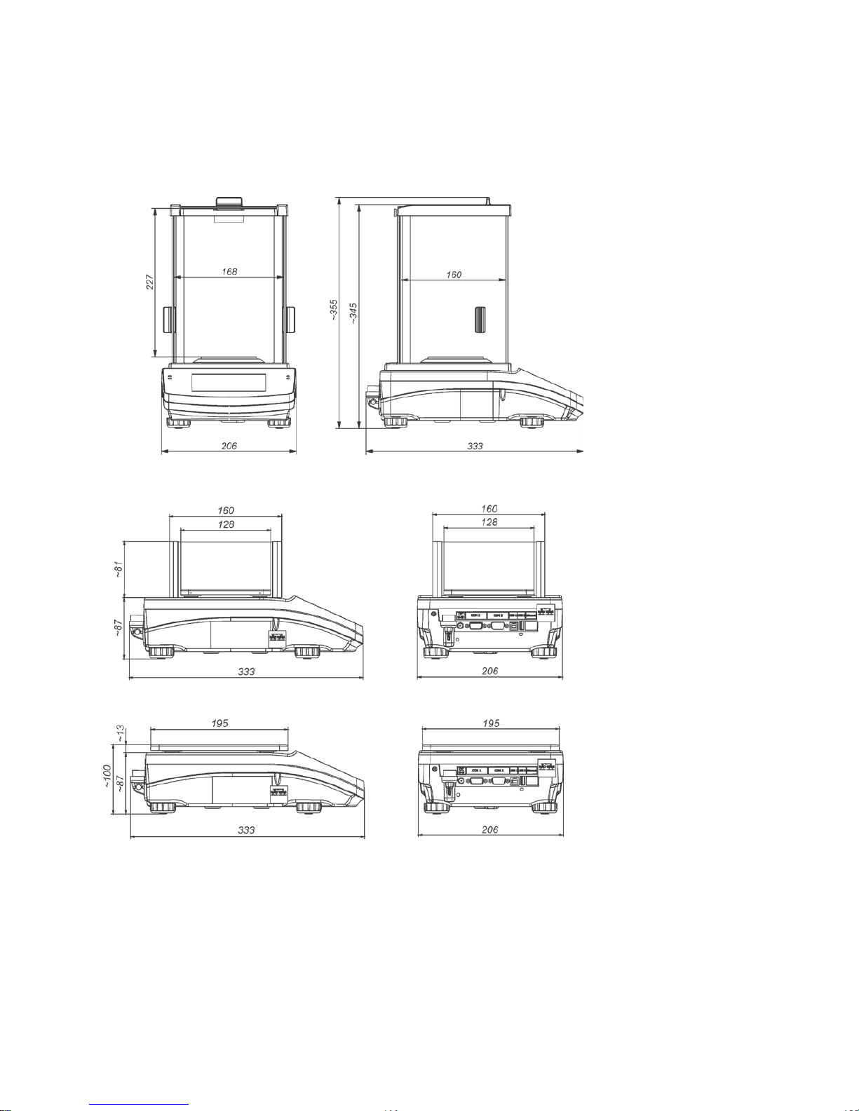
1.1. DIMENSIONS
AS X2 series
PS X2 series
Page 8

- 8 -
APP X2 series
WLC X2 series
Page 9
- 9 -
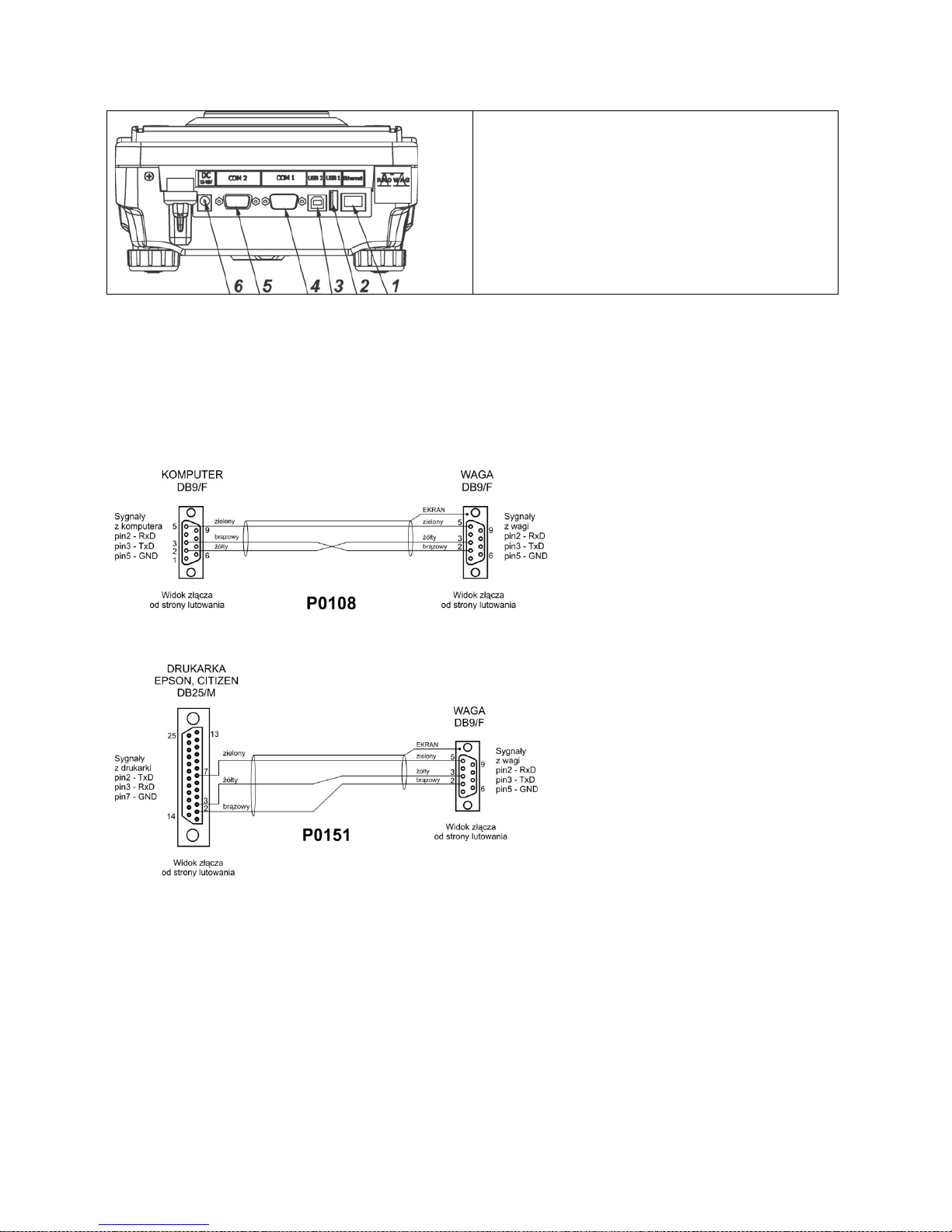
1.2. CONNECTORS
1. Ethernet RJ45 connector
2. USB 1, Type A connector
3. USB 2, Type B connector
4. COM 1 connector
5. COM 2 connector
6. Power supply socket
CAUTION!
Ethernet RJ45 connector is not applicable in WLC X2 series.
1.3. CONNECTION CABLES – DIAGRAMS
CAUTION!
„Ethernet-scale” cable is a standard network cable terminated with RJ45 on both ends.
Scale – computer cable (RS232)
Scale – printer cable (CITIZEN, EPSON)
1.4. INTENDED USE
X2 series balances are designed to provide accurate measurement of weighed loads, performed
under laboratory conditions.
1.5. PRECAUTIONS
• Prior to first use, it is highly recommended to carefully read this User Manual, and operate the
balance as intended.
• Do not operate the touch panel using sharp-edged tools (knife, screwdriver, etc.).
Page 10

- 10 -
• While loading the balance make sure that loads are placed in the very centre of the weighing
pan.
• Load the weighing pan with loads, gross weight of which does not exceed instrument’s
measuring range (maximum capacity).
• Do not leave heavy loads on the weighing pan for a longer period of time.
• In case of failure, immediately unplug the instrument from the mains.
• Balances to be decommissioned, should be decommissioned in accordance with valid legal
regulations.
• Do not use the balance is areas endangered with explosion. The X2 series is not designed to
operate in EX zones.
1.6. WARRANTY CONDITIONS
A. RADWAG feels obliged to repair or exchange all elements that appear to be faulty by
production or by construction,
B. Defining defects of unclear origin defects and means of their elimination can only be realized
with assistance of manufacturer and user representatives,
C. RADWAG does not bear any responsibility for defects or losses resulting from unauthorized or
inadequate performing of production or service processes,
D. Warranty does not cover:
• mechanical defects caused by product exploitation other than intended, defects of thermal
and chemical origin, defects caused by lightning, overvoltage in the power network or
other random event,
• balance defects if it is utilized contrary to its intended use,
• balance defects, if service claims removing or destroying protective stickers which secure
the balance’s housing against unauthorized access,
• mechanical defects or defects caused by liquids and natural wear,
• balance defects caused by inappropriate setting or by electrical wiring failures,
• defects caused by overloading the mechanical measuring system,
• maintenance activities (cleaning).
E. Loss of warranty takes place if:
• a repair is carried out outside RADWAG sales office or authorized service point,
• service claims intrusion into mechanical or electronic construction by unauthorized people,
• other version of the operating system is installed in a balance,
• the balance does not bear company protective stickers.
F. Detailed warranty conditions are listed on a service card.
1.7. SUPERVISION OVER METROLOGICAL PARAMETERS
Metrological parameters of a balance need to be checked by a user in determined time intervals.
Inspection frequency is conditioned by ambient conditions in which a balance is used, k ind of carried
out processes and adopted quality management system.
1.8. USER MANUAL SIG NIFICANCE
It is very important to read the user manual carefully before switching on and starting up balance
operation, even if you are experienced and have worked with this type of balance before.
1.9. BALANCE USER TRAINING
The balance should be utilized and supervised only by users who are trained and experienced in
such type of weighing instruments.
Page 11

- 11 -
2. TRANSPORT AND STORAGE
2.1. DELIVERY CHECKLIST
Upon delivery it is necessary to check the package, mak e sure that your package bears no signs of
damage.
2.2. PACKAGE
Keep all package elements should your device be transported in the future. Remember that only
original pack aging can be used for shipping purposes. Prior packing uncouple any cables, remove
any separable components (weighing pan, shields, inserts). Pack the device components into an
original packaging. The original packaging protects the equipment against potential damage during
transportation.
3. UNP A CKING AND INST A LLATION
Cut the adhesive tape. Take the device out of the packaging. Open the accessory box, take the
device components out of it.
3.1. PLACE OF USE AND ASSEMBLING
• The balance should be stored and used in locations free of vibrations and shakes, free of air
movement and dust.
• Ambient air temperature should not exceed the range of: +10 °C ÷ +40 °C.
• Ambient relative humidity should not exceed 80%.
• During balance operation, ambient temperature in the weighing room should not change
rapidly.
• The balance should be located on a stable wall console desk or a stable working table which is
not affected by vibrations and distant from heat sources.
• Take special precaution when weighing magnetic objects, as part of the balance is a strong
magnet. Should such loads be weighed, use under-pan weighing option, which removes the
weighed load from area influenced by the balance’s magnet. The hook for under-pan weighing
is installed in balance’s base.
3.2. STAND ARD DELIVERY COMPONENTS LIST
• balance
• bottom insert (AS balance exclusively)
• centring ring (AS balance exclusively)
• weighing pan, open-work pan for AS with d=0,01/0,1mg exclusively
• draft shield (AS and PS balances, d=0.001g, exclusively).
• power supplier
• user Manual – CD version
Page 12

- 12 -
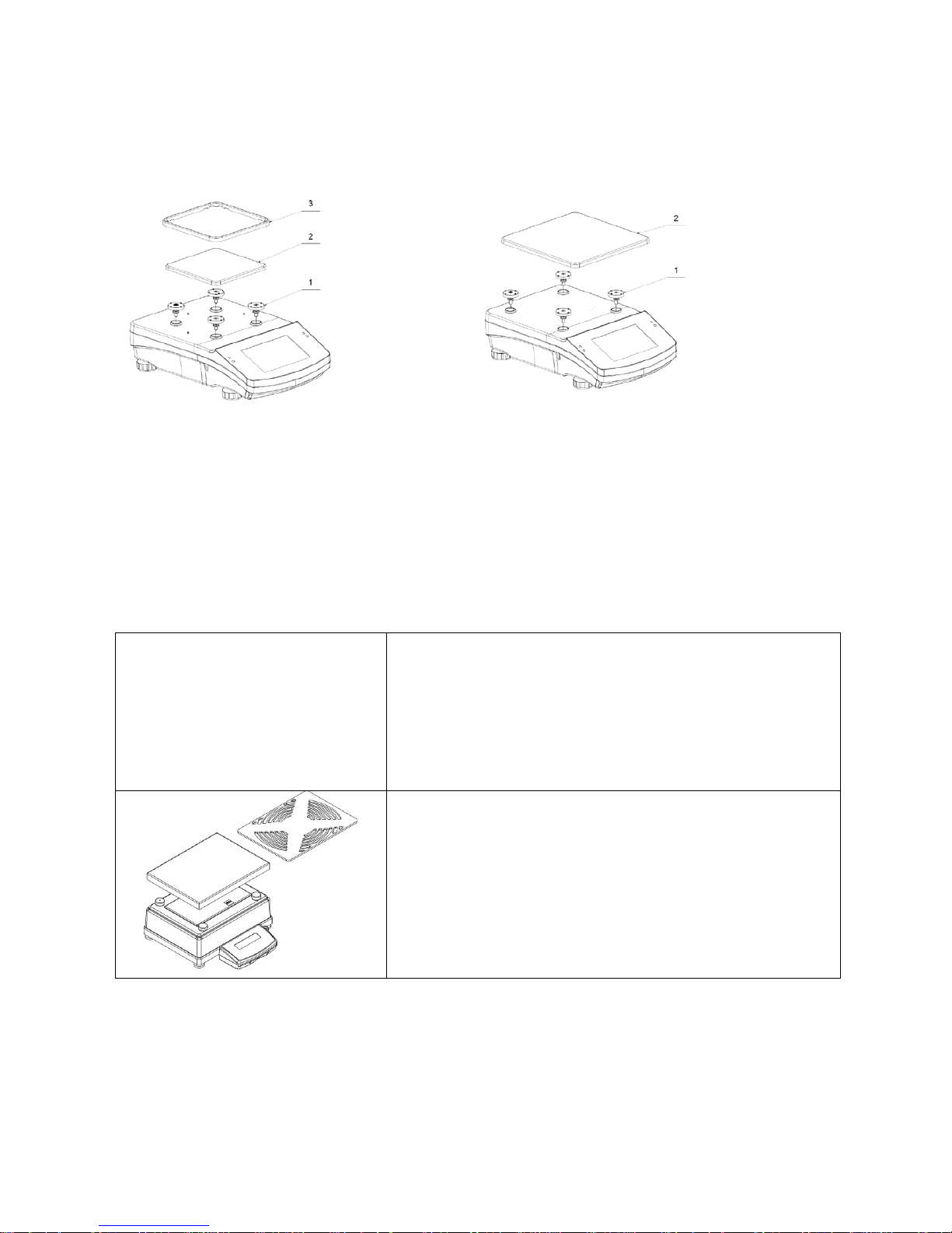
AS balance, d=0.01/0.1 mg
AS balance, d=0.1 mg
•
remove a transport lock (1) – gently press the transport lock and turn it accordingly to
<OPEN> instruction
, keep the transport lock should your balance be transported in the
future.
• Install components following the above diagram:
• bottom insert (2),
• centring ring [embossment side up] (3),
• weighing pan (4),
• draft shield (5).
CAUTION!
AS balance with d=0,01/01mg is equipped with 2 weighing pans (standard and open-work). Remember to
calibrate the balance upon changing the pan.
PS balance, d=0.001g PS balance, d=0.01g
Page 13
- 13 -
• remove tape protecting the grounding spring, located on one of the rubber mandrels (1)
• install components following the above diagram:
• weighing pan (2),
• glass draft shield (3).
WLC X2, 128x128 mm WLC X2, 195x195 mm
• remove tape protecting the grounding spring, located on one of the rubber mandrels (1)
• install components following the above diagram:
• weighing pan (2),
• glass draft shield (3).
APP balance
APP 10 balances are equipped with 2 weighing pans which can be used in turns. It must be
remembered that balance activation is only possible with one weighing pan assembled at a time.
Attempt of activating the balance with two weighing pans assembled simultaneously will result in
display of „– LH –„ error. In such case one of the pans needs to be removed.
Remove the weighing pan, next remove a transport lock (if
installed).
Undo bolt (1) installed to block adjustment mechanism.
Install a weighing pan (for APP 10 install one of the pans).
Make sure the weighing pan is placed properly on shock
absorbers: the weighing pan cannot touch the housing and
should be stable.
Page 14

- 14 -
Connect an indicator using port located at the back, next
connect supplementary equipment.
Now, connect the device to the mains (power supply socket
is located at the back).
3.3. SETTINGS
It is necessary to level the balance prior connecting it to the mains. To level the
balance turn its feet until an air bubble takes central position.
After adjusting the balance level, use a wrench (3) in order to screw a bolt (2) of foot (1), the bolt shall
touch balance housing, keep screwing until the bolt resists. Repeat this set of actions for the
remaining balance feet.
The balance shall firmly rest on a surface, each of the feet must be supported.
3.4. M AINTE N ANCE AC TIV ITI ES
1. Disassembly a weighing pan and other detachable components (the components differ
depending on a balance type – see Unpacking and Installation section). Be careful while
detaching the components so as not to cause any damages to the balance mechanism.
2. Using handheld vacuum cleaner remove dust from the weighing chamber.
3. Using a dr y flannel cloth clean glass parts (mild cleanser may be applied if it does not contain
any abrasive substances) – for draft shield disassembly instruction g o to the next section of this
manual.
4. Using a dry flannel cloth clean disassembled components (mild cleanser may be applied if it
does not contain any abrasive substances).
CAUTION!
Cleaning draft shield while still installed may cause damage of the measuring system.
In order to ease cleaning of glass draft shield panes, it is permissible to remove them following t he
below instruction.
Cleaning ABS components:
To clean dry surfaces and avoid smutching use clean non-colouring cloths made of cellulose or
cotton. You can use a solution of water and detergent (soap, dishwashing detergent, glass cleaner).
Gently rub the cleaned surface and let it dry. Repeat cleaning process if needed.
Page 15

- 15 -
In the case when contamination is hard to remove, e.g. adhesive, rubber, resin, polyurethane foam
residues etc., you can use a special cleaning agents based on a mixture of aliphatic hydrocarbons
that do not dissolve plastics. Before using the cleanser for all surfaces we recommend carrying out
tests. Do not use products containing abrasive substances.
Cleaning draft shield panes:
Select dissolvent depending on a dirt. Never soak the glass panes in alkaline solutions since they
interact with glass and may cause damage. Do not use abrasive substances.
For organic dirt use acetone first, next use water or detergent. For other than organic dirt use diluted
acid solutions (soluble salts of hydrochloric or nitric acid) or base solutions (ammonium or sodium
base).
To remove ACIDS use protofilic solvent (sodium carbonate), to remove BASE use protogenic solvent
(mineral acid of various concentration).
In case of heavy contamination use brush or detergent nevertheless avoid detergents containing
large and hard molecules which could potentially scratch glass panes.
Use soft brush with wooden or plastic handle exclusively to avaoid risk of scratches. Do not use wire
brush.
At the end of the cleaning process rinse the pane using running water first, distilled next.
Rinsing is a necessary cleaning process stage allowing to remove remaining soap, detergents and
other cleansers from the panes prior their reinstallation.
Avoid drying the panes either using paper towel or forced air circulation since some fibres, grains or
contamination of other type could permeate into the panes thus causing weighing errors.
One shall not use driers when drying measuring glass tools.
It is a frequent treatment to leave glass components on a rack to dry.
Cleaning stainless steel components:
Avoid using cleansers containing any corrosive chemicals, e.g. bleach (containing chlorine). Do not
use abrasive substances. Always remove the dirt using microfiber cloth to avoid damage of protective
coating.
In case of a daily maintenance:
1. Remove the dirt using cloth dipped in warm water.
2. For best results, add a little dishwashing detergent.
Cleaning powder-coated components:
For preliminary cleaning stage you need running water or wet sponge featuring large holes, this will
help you to remove loose, heavy dirt.
Do not use cleansers containing abrasive substances.
Next using cloth and cleanser-water solution (soap, dishwashing liquid) gently rub the cleaned
surface.
Avoid using cleanser without water since it may result with damage of the cleaned surface, please
mind that large amount of water mixed with cleanser is a must.
Page 16

- 16 -
Cleaning aluminium components:
While cleaning aluminium components use products acid by nature, e.g. spirit vinegar, lemon. Do not
use abrasive substances. Avoid using hard brush, this may cause scratches. It is recommended to
use microfibre cloth.
While polishing the surface use circular movements. Use clean, dry cloth
AS series – sequence of actions:
Undo and remove top pane
protection, next slide the pane out of
guide bar.
Remove back pane.
Remove side panes.
Side panes shall not be swapped
therefore it is necessary to remember
which one is right, and which one is
left in order to install them back
properly.
CAUTION!
Do not remove the front
pane!
Page 17
- 17 -
Remove a weighing pan, a draft
shield, a bottom insert
. Clean the
components when detached. With
this your balance mechanism is
protected against accidental
damage.
Thus prepared draft shield and panes can be properly cleaned. All the operations should be done
carefully. Pay special CAUTION to the spot where the weighing pan was installed: dirt and other
small elements might enter the balance construction through this opening, which might negatively
influence the balance parameters.
3.5. POWERING THE DEVICE
Balance can be connected to the mains only with a power adapter that comes standard with the
particular model. Nominal power supply of the power adapter (specif ied on the power adapter data
plate) should be compatible to the power from the mains.
Plug the balance to the mains – connect the power adapter to the socket, next connect its connector
to port located at the back of the balance housing.
Test of the display unit t akes place right after connecting the balance to the po wer, all the elements
and pictograms are backlit for a short time. Next, the name and the program number appears, the
indication gets to ZERO (displayed reading unit depends on the balance). During the balance start,
the test of an internal mass adjustment mechanism occurs (single location and elevation of the
internal mass adjustment).
If the indication is different than zero, please press
button.
CAUTION!
If the balance is “verified”, automatic adjustment occurs right after switching the balance on.
3.6. TEMPERATURE STABILI SATION TIME.
Before start of measuring processes, it is necessary to wait until the balance reaches thermal
stabilisation.
For balances that were stored in much lower temperatures before plugging to mains (e.g. during
winter period), thermal stabilisation period shall take at least 4 hours for PS and WLC balances, and
8 hours for AS and APP balances. During the thermal stabilization, the indications on a display panel
can change. It is recommended that ambient temperature changes at place of use were insignificant
(slow to change).
3.7. CONNECTING ADDITIONAL HARDWARE
Use only accessories and peripheral equipment recommended by the manufacturer. The balance
must be disconnected from the mains before connecting or disconnecting any peripherals (printer,
PC computer, computer keyboard). On connecting the peripherals, plug the balance to the mains.
Page 18

- 18 -
4. START-UP
• Plug the power adapter to a socket, next connect the connector to port located at the back of
the housing.
• Press button located in the top right hand corner of the terminal.
• Wait until start-up pr ocedure is completed, the home screen of balance software is displayed
automatically.
• The balance runs with no user logged in. In order to start operation it is necessary to carry out
the logging procedure (for detailed logging procedure read later sections of this user manual).
CAUTION!
Remember to start the balance with no load on the weighing pan.
5. KEYBOARD – BUTTONS FUNCTIONS
Button Overview
Press to switch the balance ON/OFF
Press to Zero the balance
Press to Tare the balance
Press to send measurement to a printer or a computer
Function key <Esc>, press to abandon parameter changes or exit to
previous menu level
Function key <Home>, press to exit to home screen
Programmable proximity sensors, press to enable operation of freely
selected functions
Page 19
- 19 -
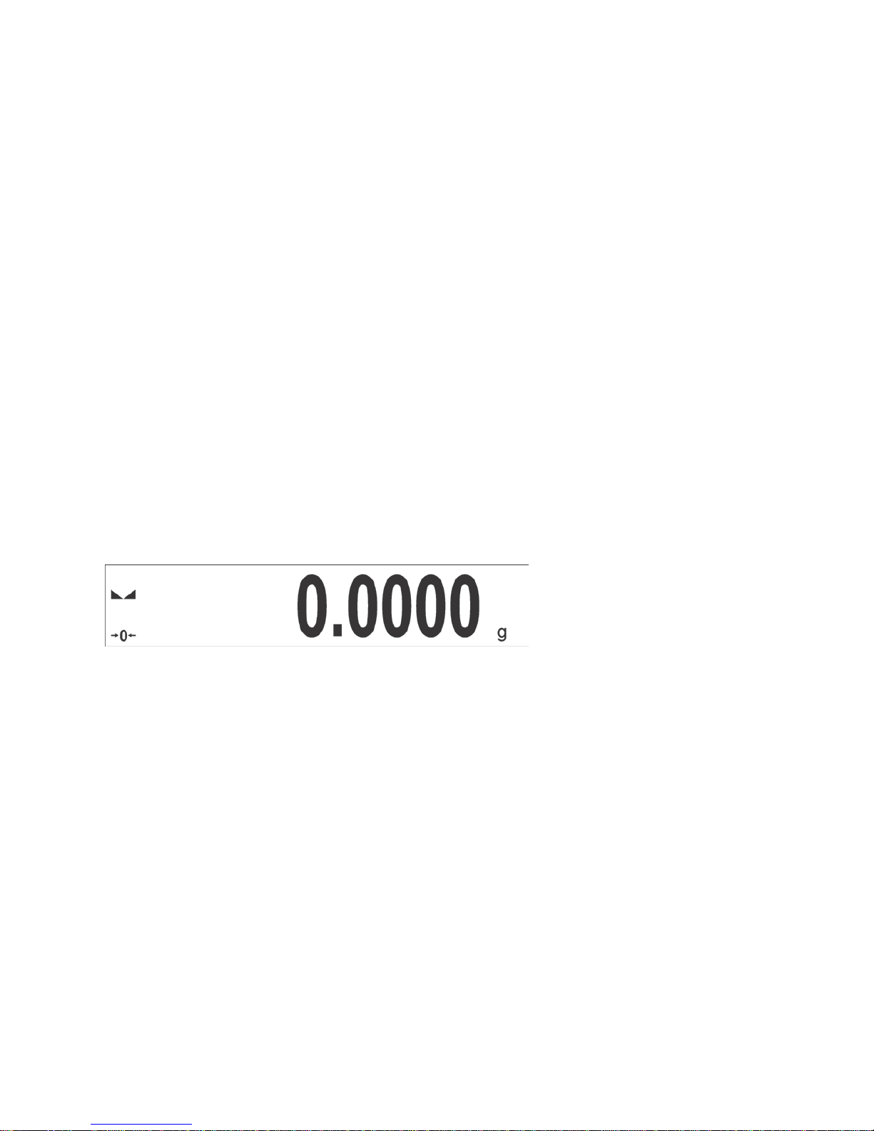
6. WEIGHING MODE HOME SCREEN
The main window of balance software can be divided into 4 sections:
• Top section displaying data on active working mode (pictogram and name), metrologically
important data and button enabling selection of functions available for a particular working
mode.
• Section presenting the weighing result.
• Section comprising supplementary information on currently performed operations, and function
buttons.
CAUTION!
Data and buttons contained in the workspace are freely configurable. For detailed information on data and
buttons configuration refer to section 7 of this user manual.
7. OPERATING BALANCE MENU
Operation of balance software menu is intuitive and uncomplicated. The touch panel makes the
software operation easy. Pressing a function key, a soft key or an area on the display initiates an
assigned function or process
Page 20

- 20 -
7.1. ENTERING BALANCE MENU
In order to enter balance menu, press
<PARAMETERS> button. Clicking any button comprised
within information section, or clicking any button with particular parameter name, results with change
of colour. This is for signalling purposes. If a given area has any function or action assigned, then it is
performed automatically upon clicking (e.g. adjustment procedure), respectively a particular window
with parameters or list of appropriate settings is displayed.
7.2. SCREEN SCROLLING
There are two methods for scrolling the screen of parameters window. The first one requires
pressing, holding down and scrolling up or down the scrollbar located on the left. The second one
requires pressing, holding down and scrolling up or down any point of the displayed window.
7.3. SOFT KEYS LIST
Press to enter the main
menu.
Press to clear the editing field.
Press to scroll the menu „up”,
or „down”.
Press to enable / disable an on-screen
keyboard.
Page 21

- 21 -
Press to confirm changes.
Press to export databases (key active
upon plugging a USB flash drive).
Press to resign form
introducing function
modifications.
Press to import databases (key active
upon plugging a USB flash drive).
Press to add a new record to
a database.
Press to select variables, out of the list,
for a printout.
Press to search for a
particular record in a
database.
Press to move (exit) one level up.
Press to print out a particular
record from a database.
7.4. RUNNINING SOFTWARE FUNCTIONS
• Quick access key,
Press to enter parameters
setup.
• Label,
Press to enter tare value.
• Text field with function assigned,
Page 22

- 22 -
Press to develop an internal
adjustment operation
(internal adjustment function
is assigned to the text field).
• Functions selections pictogram,
Press to select respective
function out of list com prising
functions available for
a particular working mode.
CAUTION!
For instruction on configuration of buttons, labels and text fields refer to section 7.6 of this user manual.
7.5. RETURN TO WEIGHING MODE
Introduced modifications are automatically saved in menu on return to the weighing mode.
press
soft key repeatedly, keep pressing
the key until the balance home screen is
displayed
press soft key located on the balance overlay
for immediate display of a home screen
7.6. BUTTONS, LABELS AND TEXT FIELDS CONFIGURATION
Area beneath weight indication section can be freely programmed. It is divided into active fields
taking form of a table: 3 rows, 10 columns.
Page 23

- 23 -
The division lines presented above are not visible on the balance screen, they serve only for informative
purposes.
This section is designed to comprise user-selected widgets: buttons, labels, text fields, bar graphs.
• button – pictogram to which a particular function is assigned, the function is triggered upon
pressing the pictogram;
• label – field for information, its content is stable. The content depends on displayed option,
wherein the options change in course of balance operation. The label may be active or passive.
Active label, when pressed, triggers function that is assigned to it, e.g. selecting product out of
products database. Passive label provides you with inf ormation on current state, no function is
assigned to it;
• text field - field for information, both content ( text and variables of line 1 and 2) and function
assigned to text field are programmable. The field may be active or passive. Its operation is
likewise as for label, the only difference is that for the text field it is the user who specifies which
function is to be assigned to it. The function does not have to ref er to displayed information,
e.g. the text field displaying date and time may trigger balance calibration upon being pressed;
• bar graph – option available f or Checkweighing and Dosing modes, f ield providing information
on Min and Max threshold - Checkweighing mode, and target weight - Dosing m ode, the given
information is presented in a graphic form, bar graph colour informs whether weight stays within
the specified tolerance or is out of it.
The section may be set up freely in a way matching your needs. Each of the modes may be
configured independently.
Set up rules:
1. Widgets dimensions (width x height)
• button – 1x1
• label – 2x1; 3x1; 4x1; 5x1
• text field – 2x1; 3x1; 4x1; 5x1; 6x1; 7x1; 8x1; 9x1; 10x1
• bar graph – 5x1; 10x1
To quickly restore the default widgets layout press any widget and hold it until a window with
available options is displayed. Select <Default screen settings> and confirm.
Exemplary arrangement and dimensions of labels and text fields.
Page 24

- 24 -
2. Always click extreme left side of a particular field that is to hold a selected widget.
3. A new widget can only take such area that holds no other widgets yet. The software automatically
detects which widgets can be applied for a particular area, this is conditioned by widget dimensions.
4. It is possible to change functions assigned to an already applied widget. The applied widget, if not
needed, can be removed.
Page 25

- 25 -
5. In order to rearrange widgets layout, it is necessar y to delete already applied widgets first, and
define new arrangement of buttons, labels and text fields next.
7.6.1. Quick Access Keys
You can define quick access keys, the keys are displayed underneath weight indication section.
Quick access key provides direct access to the most fr equently operated functions, it is select ed from
a list of available keys.
Procedure:
Press and hold for a while the spot where
a given key is to be placed.
Select option: key 1x1.
Page 26

- 26 -
Enter particular key setup.
Select the key.
The selected key is displayed automatically on
a home screen.
Page 27
- 27 -
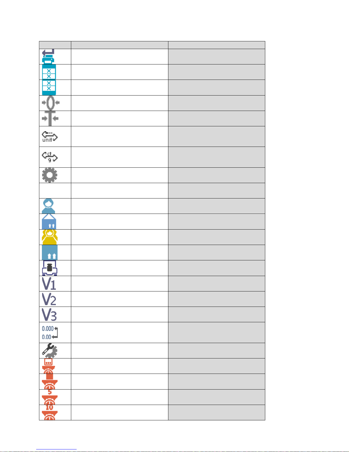
Quick access keys list:
Key
Function
Modes featuring the key
Accept/Print All modes
Print header All modes
Print footer All modes
Zero All modes
Tare All modes
Change unit
All modes (Parts Counting and
Percent Weighing modes
excluded)
Select unit
All modes (Parts Counting and
Percent Weighing modes
excluded)
Parameters All modes
Databases All modes
User All modes
Product All modes
Customer All modes
Packaging All modes
Adjustment All modes
Variable 1 All modes
Variable 2 All modes
Variable 3 All modes
Hide/show last digit
All modes (Parts Counting and
Percent Weighing modes
excluded)
Working mode parameters All modes
Set part mass Parts Counting mode exclusively
Determine part mass Parts Counting mode exclusively
Determine mass using 5 parts Parts Counting mode exclusively
Determine mass using 10 parts Parts Counting mode exclusively
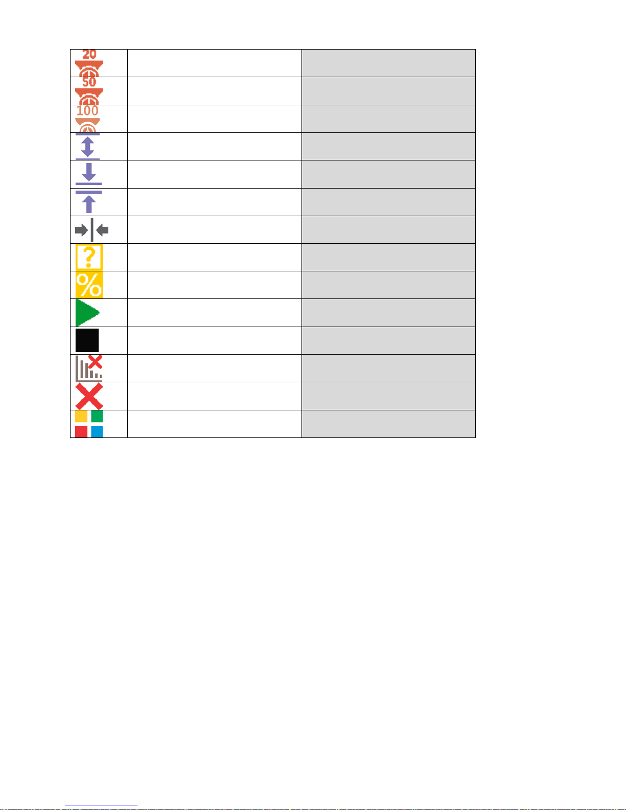
Page 28
- 28 -
Determine mass using 20 parts Parts Counting mode exclusively
Determine mass using 50 parts Parts Counting mode exclusively
Determine mass using 100 parts Parts Counting mode exclusively
Thresholds Check weighing mode exclusively
Min threshold Checkweighing mode exclusively
Max threshold Checkweighing mode exclusively
Target value Dosing mode exclusively
Set reference mass
Percent Weighing mode
exclusively
Determine reference mass (set as
100%)
Percent Weighing mode
exclusively
Start
Solids and Liquids Density modes
and Formulations mode
Results Statistics mode exclusively
Finish Statistics mode exclusively
Finish Peak Hold mode exclusively
Formulation Formulations mode exclusively
7.6.2. Labels
You can select label size and type of information to be displayed for a particular label.
In order to select a particular label, use a list of available labels. Upon label selection, specify type of
information to be displayed for the label. The selected label is d isplayed autom atically on a specified
home screen spot.
Procedure:
Press and hold for a while the spot where
a given label is to be placed.
Page 29

- 29 -
Select a label and its size.
Label settings window opens, click
INFORMATION field in order to see a list of
information type available for the selected
label.
Select data to be displayed.
The selected label is displayed automatically
on a home screen.
Information type:
Label information type Modes featuring the information
Date
All modes
Time All modes
Date and time All modes
Net weight All modes
Tare
All modes
Page 30

- 30 -
Gross weight
All modes
User
All modes
Product All modes
Packaging
All modes
Customer All modes
Variable 1
All modes
Variable 2 All modes
Variable 3 All modes
MSW value Weighing mode exclusively
MSW tare
Weighing mode exclusively
MSW status Weighing mode exclusively
Part mass
Parts Counting mode exclusively
Thresholds Checkweighing mode exclusively
Min threshold
Checkweighing mode exclusively
Max threshold Checkweighing mode exclusively
Target value Dosing mode exclusively
Reference mass Percent Weighing mode exclusively
Weigh i ng in air
Solids and Liquids Density Determination modes
exclusively
Weighing in liquid
Solids and Liquids Density Determination modes
exclusively
Liquid Solids Density Determination mode exclusively
Temperature Solids Density Determination mode exclusively
Liquid density Solids Density Determination mode exclusively
Sinker volume
Liquids Density Determination mode exclusively
Number Statistics mode exclusively
Sum
Statistics mode exclusively
Mean Statistics mode exclusively
Min Statistics mode exclusively
Max Statistics mode exclusively
Difference
Statistics mode exclusively
SDV Statistics mode exclusively
RDV
Statistics mode exclusively
Threshold Peak Hold mode exclusively
Formulation Formulation mode exclusively
Sum Formulation mode exclusively
Target value
Formulation mode exclusively
The above presented information type has been designed for WEIGHING working mode.
The information may vary depending on the working mode and functions relating to the particular
mode. Detailed description for a given information type is provided within section overviewing
a respective mode.
Page 31

- 31 -
7.6.3. Text fields
You can select text field size and type of information to be displayed in the first and the second line of
the field, plus you can decide on a function that is to be assigned to a particular text field.
Upon completed setup operation, the selected text field is displayed automatically on a specified
home screen spot.
Page 32

- 32 -
Procedure:
Press and hold for a while the spot where
a given key is to be placed.
Select text field and its size.
Text field settings window opens.
Define particular text field parameters:
•
Line 1: e.g. text <Time: >,
•
Line 2: e.g. variable {3}, variable for
current time displaying (other
variables refer to point for nonstandard printouts defining),
Page 33

- 33 -
•
function: e.g. adjustment.
When all text field parameters have been
defined, the window displays respective
values.
The defined text field is displayed
automatically on a home screen.
7.6.4. Bar graphs
Bar graph function is accessible f or all weighing modes. The bar graph presents in a graphic form
how much of balance capacity is in use. Additionally it sho ws Min and Max thresholds positions for
Checkweighing mode, and for Dosing mode it shows target weight value along with permissible
tolerance.
You can select bar graph size and turn on/off <Zoom> function. This function rescales bar graph in
order to improve visualization of indication.
Procedure:
Press and hold for a while the spot
where bar graph is to be placed.
Page 34

- 34 -
Select bar graph and its size.
Bar graph settings window opens.
The selected bar graph is displayed
automatically on a home screen.
Example for bar graph with <Zoom> function on:
Example for bar graph with <Zoom> function
off:
8. WEIGHING OPERATION
Load a weighed object on a balance weighing pan. On stabilization of weighing result, indicated by
stability marker
visible on the left side of balance display, read the measurement result.
Record / printout of the measurement result is available on pressing <PRINT> key:
• for verified balances – only stable measurement result can be saved or printed (stability marker
visible on balance’s display),
Page 35

- 35 -
• for non-verified balances – stable or unstable measurement result can be saved or printed
(regardless of stability marker
absence). If unstable measurement result is printed then it is
accompanied by question mark <?> in front of printed mass value.
8.1. GOOD WEIGHING PRACTICE
In order to ensure long lasting use of a balance plus correct and reliable measurement of weighed
loads, follow below procedures:
• Start the balance with no load on the weighing pan (permissible value of load on the weighing
pan on balance start is ±10% of its maximum capacity).
• Load the weighing pan steadily avoiding shocks:
YES
NO
• Place weighed loads centrally on the weighing pan:
YES
NO
• Avoid side loading, in particular side shocks:
NO
NO
8.2. LOGGING
Full access to user parameters and to editing databases requires logging as an operator with
<Administrator> permissions level. The logging procedure should be carried out on each switching
on of the balance.
First Log In operation - procedure:
• Run home screen and press < > button, operators database window opens with list of
available users,
• Select <Admin> option, the software activates an on-screen keyboard, use it to enter operator’s
password: „1111”,
• Press button to confirm,
• Home screen of the software is displayed again automatically,
Page 36

- 36 -
• When logged, add users and set the permissions levels (for the procedure of assigning
permissions levels read section 23).
On future Logging In, select a user from the list and enter the password, the software initiates
operation with permissions level set for the selected user.
Log out operation – procedure:
• Run home screen and press < > button, operators database window opens,
• Press <Log out> soft key (located as position no. 1 in the list of operators),
• Home screen of the software is displayed again automatically.
Permissions levels
Balance software comprises three permissions levels: administrator, advanced operator, user.
Permissions level dependent access to edition of user parameters, databases and software
functions.
Permissions levels Enabled operations
User
Free editing of parameters of <Readout> submenu. Modification of
settings for <Misc.> parameter group, except for settings for <Dat e and
Time>.
The operator can start and carry out all weighing processes.
The operator can preview information recorded in <Databases>, (s)he
can define universal variables.
Advanced User
Free editing of parameters of the following submenus: <Readout>;
<Working modes>; <Communication>; <Peripherals>; <Misc.>.
Access to <Date and Time> submenu denied.
The advanced operator can start and carry out all weighing processes.
Administrator
Access to all user parameters and functions, editing databases
enabled.
8.3. UNITS
UNITS parameter group enables you to change availability of mass units (the change can be
performed in-course of balance operation), and to define two custom units, thus posit ively effecting
comfort and speed of operation. It is possible to change unit to other than unit [g] during weighing
process or during operation of other modes. Working mod es Parts Counting and Percent Weighing
are exceptions.
8.4. WEIGHI NG UNIT SELECTION
Change of weighing unit is carried out by pressing the weighing unit icon visible next to the value of
measurement result, or by clicking key (if displayed in an information section). Clicking the unit
triggers its replacement, the clicked unit is replaced with the unit that is next on the list of available
units.
Another option for unit replacement is selecting a particular unit out of the units list, to view the list
click key (if displayed in an information section).
Units list:
Unit
Denotation
Verified balance
gram [g] yes
milligram [mg] yes *
Page 37

- 37 -
kilogram [kg] yes *
carat
[ct]
yes *
pound [lb] no
ounce
[oz]
no
ounce Troy [ozt] no
pennyweight
[dwt]
no
Taele Hongkong [tlh] no
Taele Singapore [tls] no
Taele Taiwan [tlt] no
Taele China
[tlc]
no
Momme [mom] no
Grain
[gr]
no
Newton [N] no
Tical
[ti]
no
baht [baht] no
tola [tola] no
mesghal [msg] no
* - Accessibility of measuring units is conditioned by balance type.
8.5. WEIGHI NG UNITS ACCESSIBILITY
You may declare which units shall be accessible while selecting a temporary unit by means of
key. Units with parameter value set to <Yes
> option are available for selection in particular
working m odes, i.e. modes facilitating units change.
Units with parameter value set to <No >
option will not be accessible while operating the
balance.
8.6. START UNIT SELECTION
Upon selection of start unit, the balance activates with the specified start unit for these modes wher e
change of the unit is possible.
Ability of selecting a given unit depends on the balance status, i.e. if the balance is verified or not.
Page 38

- 38 -
8.7. USER-DEFINED UNI T
You may declare two units. Displayed value of a user-defined unit is a multiplication of measured
mass value and a coefficient specified for the particular user-defined unit. The units can be freely
named with use of 3 characters maximum. By default the names are displayed as [u1] – user unit 1,
and [u2] – user unit 2.
8.8. BALANCE ZEROI NG
Zeroing is a function allowing to zero mass indication. In order to zero mass indication, press
button. Mass indication of zero value shall be displayed together with precise zero
and stability
markers.
Zeroing process is an equivalent for determining new zero point, recognized by the balance as
precise zero. Zeroing is possible only for stable status of display indication.
CAUTION!
Zeroing the display indication is possible only within ±2% range of instrument’s maximum capacity. If the
zeroed value is above ±2% of the maximumcapacity, then the software indicates a respective error message.
8.9. B ALAN C E TARING
Taring is a function allowing to determine net weight of a measured object. In order to det ermine net
weight of the object, place object’s container (packaging) on the weighing pan, and on stabilization of
measurement result press
key. The display indicates mass equal zero and symbols: Net and
. On taking off the weighed load and its packaging from the weighing pan, the display indicates
sum of total tared mass with minus sign.
Page 39

- 39 -
The software enables assigning tare value to a database-stored product. Using this option, the
software automatically uploads data on tare value for a particular product upon its selection from the
database.
CAUTION!
Taring negative values is impossible. On taring negative values the balance responds with an error message.
In such case, zero balance indication and repeat taring procedure.
Manual tare determination
Procedure:
• While in optional mode press quick access key ,
• An on-screen numeric keyboard is displayed,
• Enter tare value and press key,
• The balance returns to the weighing mode, and the display indicates entered tare value with
minus ‘–‘ sign .
Page 40

- 40 -
Deleting tare
The tare value indicated on balance display can be deleted by pressing
key on balance
overlay, or by using programmable function key <Deactivate tare>.
PROCEDURE 1 - on taking the tared load off the weighing pan
• Press key.
• The NET marker is deleted, and new zero point of the balance is determined.
PROCEDURE 2 – with tared load on the weighing pan
• Press key.
• The NET marker is deleted, and new zero point of the balance is determined.
• When tare value exceeds 2% of the maximum capacity, respective message is displayed in
order to inform a user about the fact.
Selecting tare value out of TARE DATABASE
Procedure:
• While in optional mode, press button located in a top left hand corner of the mass
display.
• Wait for a respective window to open, next select <PACKAGING>.
• Window with a list of tare values recorded into tare database opens.
• Select the packaging that is to be used.
• The balance returns to the weighing mode, and the display indicates sel ected tare value with
a minus ‘–‘ sign.
or
• While in optional mode, press button (if displayed on the screen),
• Window with a list of tare values recorded into tare database opens.
• Select the packaging that is to be used.
• The balance returns to the weighing mode, and the display indicates sel ected tare value with
a minus ‘–‘ sign.
AUTOTARE function
Autotare function provides automatic taring of the packaging during the weighing process when
packaging mass for each of the product is different. Description of this function is to be f ound further
down this manual.
Deleting tare
Entered tare value can be deleted by pressing
button on the overlay or by entering tare value
of 0.000g (see description above).
8.10. WEIGHING MODE SETTINGS
The software allows setup of operating parameters (filters, value release and autozero function,
deleting the last digit and other settings) separately for each working mode.
It enables customizing the instrument and utilizing its properties depending on your needs and
expectations, or on specific requirements for selected working mode (e.g. DOSING); as a r esult the
device operation is quick and easy.
Page 41

- 41 -
Filter level setting
Filter settings adjustment depends on the working environment. For the best possible conditions the
filter can work in a very fast mode (V.FAST value for Filter parameter); however, if the conditions are
poor (shakes, drafts), the filter should be set to slow or very slow option (SLOW or V. SLOW value for
Filter parameter). The effectiveness of the filter is different throughout the weighing range. The filter
works slower when “approaching” the weighed mass, it works more intensively for weighed mass
within the set range of the filter (parameter for setting filter range is accessible only fr om the service
menu – the user does not have any access to it).
Depending on the filter, the weighing time is shorter (V.FAST and FAST) or longer (SLOW and V.
SLOW).
CAUTION!
The higher filter level, the longer weighing time.
Value release
Since ambient conditions at a workplace vary, it is necessary to determine the value release
parameter in the most preferable way enabling balance adaptation, parameter options are:
FAST.+REL., FAST or RELIABLE. Depending on the selected option, weighing time is either shor ter
or longer.
Autozero function
The software features an autozero function (Auto) ensuring precise mass indication. This function
automatically controls and corrects zero indication. When Autozero is enabled, it compares balance
indications at declared time interval e.g. 1s, provided that weighing pan is unloaded and display
indication is close to zero. If results vary less than declared AUTOZERO range e.g. one division,
Page 42

- 42 -
balance zeroes automatically, marker of stable measurement result –
, and precise zero marker –
are displayed.
If AUTOZERO function is enabled, then each weighing process starts from precise zero point. There
are, however, some cases when this function can be a disturbing factor for the m easuring process;
e.g. very slow placing of a load on the weighing pan (load adding). Here, zero indication correction
can also correct actual indication of loaded mass.
Last digit display
Function enables displaying the last digit of decimal place for a weighing result. There are three
available options:
• Always: all digits visible,
• Never: last digit is not displayed,
• When stable: last digit is displayed only for a stable weighing result.
Balance ambient conditions
Parameter relating to ambient and environmental conditions in which the balance operates. There
are two options: STABLE and UNSTABLE. Selecting STABLE mode makes the balance work much
faster, i.e. weighing takes much less time than for UNSBABLE mode. If the ambient conditions are
unstable it is recommended to use UNSTABLE mode. By default, the paramet er is set to STAB LE
option.
8.11. PROXIMITY SENSORS
The balance features two proximity sensors enabling touch-free balance control.
The software detects two motions performed around the sensors:
1. hand in a close vicinity to the left sensor <Left sensor>,
2. hand in a close vicinity to the right sensor <Right sensor>.
Each motion can trigger optional balance function. For available functions list refer to point 7.6.1.
Upon completed configuration procedure, the software runs function assigned to a particular
proximity sensor having detected motion around it. To provide correct operation, it is necessary to set
the right proximity sensors sensitivity (read point 9 for detailed instruction).
8.12. AUTOTARE
Autotare is used for quick determination of net weight for loads with different tare values, wherein
they are measured one after another.
When the function is active (<AUTOTARE> parameter set to <YES> option), the operating process
takes the following steps:
• Make sure that the weighing pan is empty and press button responsible for zeroing,
• Put product packaging on a weighing pan ( packaging weight value must be greater than set
AUTO THRESH value),
• After measurement stabilization, automatic taring of the packaging mass proceeds (Net
marker appears in the upper part of the display),
• Put product that is to be packed into the packaging;
• The display shows net weight of the product;
• Take off the product together with the packaging;
• The balance cancels tare value (packaging weight recorded in balance storage dur ing the first
step of the operating process) after the gross mass value (set in <AUTO THRES> parameter)
has been exceeded; the entered tare value is cancelled automatically (Net marker disappears
from the top section of the display), net weight is displayed;
• Put packag ing of the next product on a weighing pan, automatic taring of the packaging weight
proceeds after measurement stabilization (Net marker appears in the top section of the
display);
• Put a next product that is to be packed.
Page 43

- 43 -
For correct operation of the balance with AUTOTARE function it is necessary to adjust the threshold
value.
<AUTO THR ES> parameter is connected with the following functions:
• automatic tare,
• automatic operation,
No automatic taring takes place as long as the gross weight value stays within the range set in
<AUTO THR ES> parameter.
8.13. PRINT MODE
Function designed to enable print mode setting, it activates
key.
Print mode options:
• <WHEN STAB>, for this option stable measurement result, along with the settings for
parameter <GLP PRINTOUT>, is sent to the printer port. On pressing key, when the result
is not stable (no
marker on a display), the balance soft ware sends the measurement result
to the port after reaching stability for the measurement.
• <EACH>, for this option every single pressing of button results with sending the
measurement indication to the printer port along with the settings for <GLP PRINTOUT>
parameter. Every single indication is sent (stable and unstable). For unstable indication <?>
character appears at the beginning of the printing frame.
This function applies to non-verified balances exclusively.
• <AUTO> - select this option to enable automatic printing of measurements. If this option has
been selected, remember to set <AUTO THRES> parameter to suit your needs.
Automatic operation procedure:
• Press butt on to zero the balance (marker of stable measurement and zero marker
are shown on a display)
• Deposit load, the balance sends the first stable measurement to the pr inter port,
• Remove the load from the pan,
• Next measurement is possible when the indication is lower than the set value of <AUTO
THRES.> parameter (next measurement does not require zero value).
For automatic operation adjust the threshold value. For automatic operation, the measurement will
not be send from the computer to the printer as long as the mass measurement stays within the set
value range <AUTO THRES>.
<AUTO THR ES> parameter is connected with the following functions:
• automatic tare,
• automatic operation,
• auto with interval.
<AUTO+INT.> select this option to start automatic printout and record of indications in Weighings
database and Alibi database, carried out in a cyclic manner in a specified time interval. The interval is
set in minutes, in parameter P2.2.3.3 <AUTO INT.>. Interval range is 1-9999 min.
CAUTION!
Each result is printed and recorded (stable and unstable for a non-verified balance, stable for a verified
balance).
Automatic operation with interval starts at the moment of switching the function on and it lasts until it is switched
off. The first stable weighing result of value greater than AUTO THRES value is printed as a first measuremnt.
The following measurements are printed with frequency set in INTERVAL parameter. Automatic operation with
interval stops when the option is off.
On switching the function of auto print with interval, PRINT button becomes inoperative (no indication is printed
when pressed).
Page 44

- 44 -
8.14. MINIMUM SAMPLE WEIGHT
Weighing mode comprises <Minimum sample weight> function. In order to use this function it is
necessary to enter minimum sample weight (MSW) value and tare values for which the MSW value is
to be obligatory. For standard X2 series models the values equal zero.
Only authorized RADWAG employee or operator with Administrator permissions level, providing that
balance factory settings enable this, can carry out procedure aiming to determine minimum sample
weight and next enter the respective data.
If you want to use this function, and your balance menu contains no minimum sample weight data,
ask the nearest RADWAG office for help.
Authorized RADWAG employee determines minimum sample weight for specified tare containers,
using. The determination is carried out using mass standards on site, requirements of applied quality
system are adhered to. Obtained value is entered into software, <Minimum sample weight>.
Balance software enables defining tare value with assigned minimum sample weight value.
<Minimum sample weight> function guarantees that results of weighing operation are comprised
within set tolerance, accordant to applied quality management system of particular company.
Caution! This function is valid for weighing mode exclusively.
Options:
• Mode
None – minimum sample weight function off
Block – select to make the balance display respective pictograms informing on mass (whether
it is out-of-tolerance low or out-of-tolerance high); with this option on, the software disables
confirmation of the measurement that is out-of-tolerance low
Warn – select to make the balance display respective pictograms informing on mass (whether
it is out-of-tolerance low or out-of-tolerance high); with this option on, the software enables
confirmation of the measurement that is out-of-tolerance low
• Tare – maximum tare value for which minimum sample weight value is obligatory (read
examples below)
• Minimum mass – minimum sample weight determined for particular balance on site using
respective method.
Example 1 for AS 220.X2 with d=0.0001 g:
No.
Tare value
Minimum
Sample
Weight
Operation
2
10.0000 g
1.0000 g
Minimum sample weight refers to all net weights subjected
to weighing in a tare container of mass 0,0001g – 9,9999g
inclusive (<TARE> button used). The program identifies
setting specifying that minimum sample weight is valid
exclusively
for samples weighed in a tare container of
weight
covered by the above specified range. If taring
function is not used or tare container weight is covered by
range 10,0000g – Max, then pictogram informing on use of
minimum sample weight goes blank.
Example 2 for AS 220.X2 with d=0.0001 g:
No.
Tare value
Minimum
Sample
Weight
Operation
1
220.0000 g
0.5000 g
Minimum sample weight refers to all net weights subjected
to weighing in a tare container of
mass covered by full
weighing range (<TARE> button used).
The program
identifies setting specifying that minimum sample weight is
valid exclusively for samples weighed in a tare c ontainer. If
taring function is not used, then pictogram informing on
Page 45

- 45 -
use of minimum sample weight goes blank.
Example 3 for AS 220.X2 with d=0.0001 g:
No.
Tare value
Minimum
Sample
Weight
Operation
1
0.0000 g
0.2500 g
Minimum sample weight refers to all net weights subjected
to weighing where no tare container is used (<TARE>
button not used). The program identifies setting specifying
that minimum sample weight is valid exclusively for
samples not weighed in a tare container. If taring function
is used, then pictogram informing on use of minimum
sample weight goes blank.
As a user you can preview entered data, but you are not allowed to edit it.
Weighing with use of <MINIMUM SAMPLE WEIGHT> function.
If in course of weighing you want to obtain inf ormation st at ing whether par t icular measurement is outof-tolerance high, specified for minimum sample weight, then <Minimum sample weight> function
shall be on, to turn the function on go to weighing mode settings.
Procedure (Administrator exclusively):
1. Weighing mode settings,
2. Press <Minimum sample weight> field,
3. Press <Mode> field,
4. Settings window is displayed with the following options:
Block – select to make the balance display respective pictograms informing on mass (whether
it is out-of-tolerance low or out-of-tolerance high); with this option on, the software disables
confirmation of the measurement that is out-of-tolerance low,
Warn – select to make the balance display respective pictograms informing on mass (whether
it is out-of-tolerance low or out-of-tolerance high); with this option on, the software enables
confirmation of the measurement that is out-of-tolerance low.
5. Select respective option and return to the home screen
6. Section presenting the weighing result comprises additional pictogram providing supplementary
information. The pictogram changes in course of weighing operation informing you on the
weighed sample mass with reference to declared minimum sample weight value
Weight value lower than minimum sample
weight specified for a particular tare range.
Weight value higher than minimum sample
weight specified for a particular tare range.
Pictograms for minimum sample weight:
Weight value lower than specified minimum sample weight
Weight value higher than or equal to specified minimum sample weight
CAUTION!
If more than one reference tare value has been programmed (along with min load values assigned to them)
then indicated value automaticaly turns to range respective for tare container weight. Requested minimum load
changes simultaneously.
Page 46

- 46 -
8.15. COOPERATION WITH TITRATORS
In order to provide correct cooperation with Titrators, go to settings of standard printout content and
set <Mass value for a titrator> parameter t o <Yes> value. With this, other variables for the printout
are turned off.
With <Yes> value on, a respective pictogram is displayed in the top bar
of a home screen. The
pictogram informs on special format of mass printout, tolerable by TITRATORS.
8.16. DUAL RANGE BALANCES AND WEIGHING
(refers PS 200/2000.X2 and WLC 1/10.X2 balances)
An example for PS 200/2000.X2 balance
PS 200/2000.X2 balance is a dual range weighing device with readability for I w eighing r ange d
1
=
0.001g, and d
2
= 0.01g for II weighing range.
Transition from weighing with accuracy of the I weighing r ange to weighing with accuracy of the II
weighing range takes place automatically on exceeding Max1 200g. On entering the accuracy of the
II weighing range, the display indicates II pictogram on its right side, last but one digit turns to grey
colour.
From now on the balance continues weighing in the II weighing range.
Page 47

- 47 -
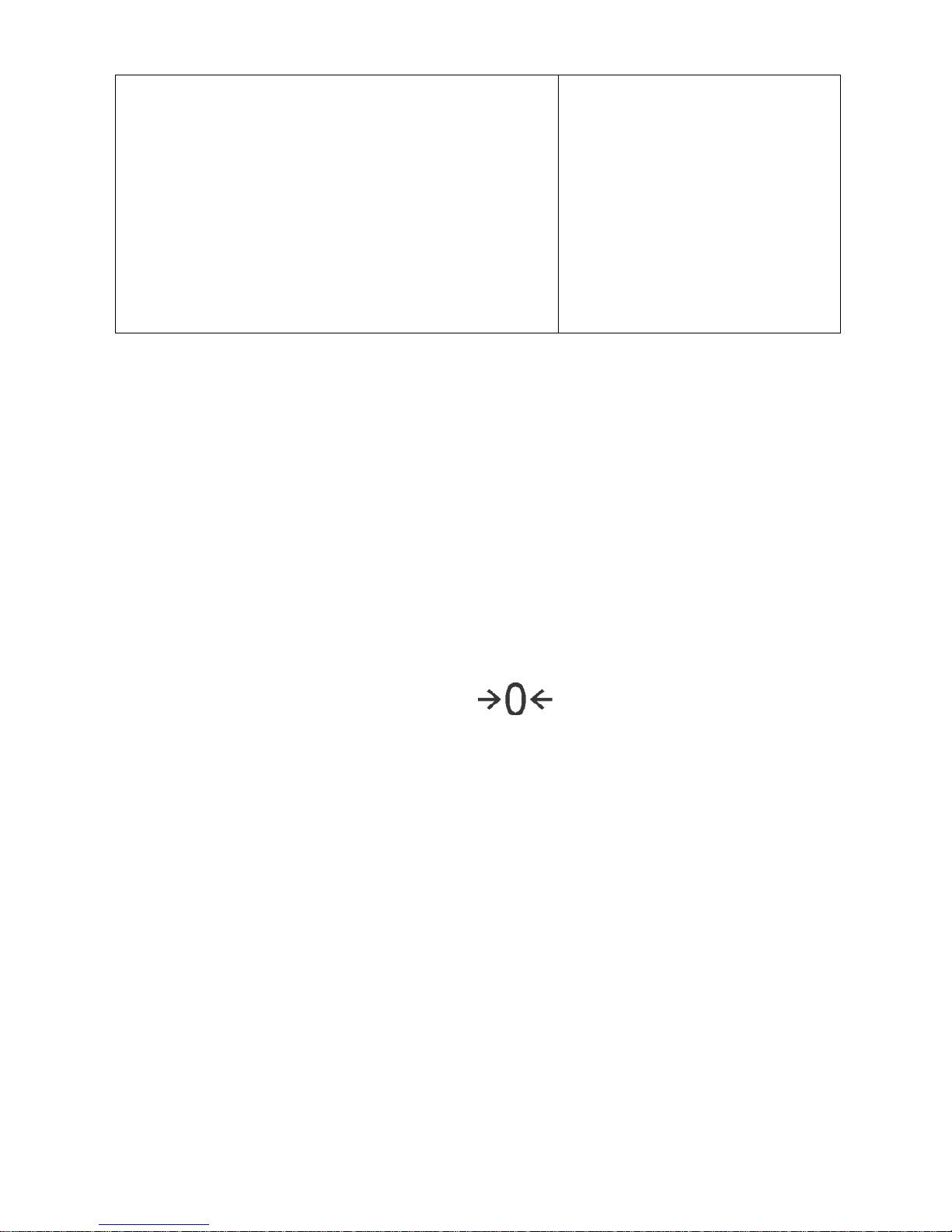
To return to weighing with accuracy of the
I weighing range:
• take the load off the weighing pan
• as the indication returns to zero and when symbols
→0←
and are displayed, press
button
The balance returns to weighing with readability d
1
=0.001g, the II weighing range symbol gets
blanked, last but one digit is no longer grey.
9. MISCELLANEOUS PARAMETERS
A user can set up parameters which influence balance operation. These parameters are to be found
in parameters group MISC.
Settings modification for particular parameters of this parameter group proceeds likewise as
described in point 7.
Menu language
Language parameter enables selecting the language of the balance menu descriptions.
Available languages: POLISH, ENGLISH, RUSSIAN, SPANISH, FRENCH, GERMAN, ITALIAN,
CZECH, CHINESE, ARABIC, TURKISH, KOREAN.
Permissions
Permissions parameter enables choosing access level for a particular user, one that is not logged in.
Available access levels: ADMIN. / USER. / ADV.
Depending on selected permissions level, you can enter balance parameters and modify the settings,
as far as possible for a particular level. Logging in operation is not required (for permissions overview
read point 8.2).
„Beep” sound – reaction to operation of pressing a key
Sound parameter enables switching on/off a ‘beep’ sound responsible for informing a user about
pressing any key of balance overlay or display, or about proximity sensors response.
Procedure:
Page 48

- 48 -
Backlight and adjusting display brightness
Display brightness parameter enables setting the brightness of the backlight or switching off the
display brightness completely.
Procedure:
Proximity sensors sensitivity adjustment
Proximity sensors sensitivity parameter specifies distance within which the sensors can be operated,
its scale is expressed in percent and it ranges from 0% to 100%. For lower percent value the
proximity sensors operate at a shorter distance.
Usually the sensitivity value is comprised within 50%-70% limits.
Procedure:
Date
Date parameter enables setting the current date.
Procedure:
Page 49

- 49 -
Time
Time parameter enables setting the current time. Procedures for change of time settings and date
settings are likewise.
Date format
Date form. parameter enables altering the date f ormat on the print out [ YYYY.MM.DD / YYYY.DD. MM
/ DD.MM.YYYY / MM.DD.YYYY], where: YYYY – year; MM – month; DD – day.
Time format
Time form. parameter enables specifying time format for a printout [12h / 24h].
For [12h] option selected, <A> or <P> letter is displayed next to presented time value, where: A
stands for hours before noon; P stands for hours after noon.
Backlight turn-off time
<BACKLIGHT OFF> parameter enables activation of display stand-by mode, the stand-by mode is
activated when no weighing process is carried out (stable indication is a necessary condition for
activation of the stand-by mode).
NONE – backlit turn-off time not activated.
0.5; 1; 2; 3; 5 – time given in minutes.
If the software registers stable indication for a specified time interval, set in parameter <BACKLIGHT
OFF>, than the display goes out immediately. The backlight activates upon change of indication (no
stability pictogram on the display) or pressing any key on the balance keypad. The display remains
blank also when balance menu is entered.
Auto switch-off
<AUTO OFF> parameter enables automatic display deactivation (the parameter functioning is
likewise to
button functioning). Upon display deactivation the other subassemblies are powered
and the balance turns to stand-by mode.
NONE – auto switch-off not activated.
0.5; 1; 2; 3; 5 – time given in minutes.
If the software registers stable indication for a specified time interval, set in parameter <AUTO OFF>,
than the display is turned-off immediately.
To start-up the balance, it is necessary to press
button located on the balance keypad. The
balance automatically returns to weighing operation.
Balance cannot be turned off if any process is started or if balance menu is entered.
Autotest GLP
AUTOTEST GLP function is designed to aid a user in assessing balance’s operation and diagnosing
the reasons for occurrence of errors in weighing which exceed the maximum permissible values for a
given balance model.
By means of a simple, repeatable and fully documented way, the function enables optimizing
balance’s settings to maintain the best possible repeatability and weighing time at workstation. The
main purpose of the function is the possibility of monitoring the above-mentioned parameters at
Page 50

- 50 -
optional moment and saving records from the carried out tests in the form of printed reports of the
tests that are automatically generated at the end of examination. Up to 50 reports can be recorded.
The test controls repeatability of placing the interval weight and det ermining error of indication with
reference to balance’s maximum capacity.
Testing procedure:
• deposit internal weight twice,
• deposit internal weight ten times, calculate the value of standard deviation,
• perform balance adjustment,
• print a report.
Test results provide balance data, calculated error for Max capacity and value of repeatability of
indication expressed as standard deviation.
An exemplary report:
.....................................................
--------- Autotest GLP: Report ---------
Balance type PS 3000.R2
Balance ID 400010
User Admin
Software rev. v.0.4.9
Date 2013.07.16
Time 09:17:16
----------------------------------------
Number of measurements 10
Reading unit 0.001/0.01 g
Internal weight mass 1402.094 g
Filter Average
Value release Fast &Reliable
----------------------------------------
Deviation for Max. -0.118 g
Repeatability 0.0088 g
Signature
........................................
Procedure:
Enter <OTHER> parameters’ group, start <AUTOTEST GLP> parameter.
Press <Start> field. Autotest GLP procedure starts, it is carried out automatically. Autotest procedure
progress bar is displayed.
Press
or button to abort the procedure, you can do it at any time.
Page 51

- 51 -
On completed procedure the parameter screen is displayed, value informing on recorded autotest
number, to be found in <RESULT> field, is increased by <1>. To view particular results press
<RESULTS> field and select the given autotest.
To print a report go to <Details> window and press printer pictogram. The software can store up to 50
reports.
10. ADJUSTMENT
In order to ensure the highest weighing accuracy, it is recommended to periodically introduce a
corrective factor of indications to balance memory, the said factor must be referred to a mass
standard. In other words, balance adjustment shall be performed from time to time.
Adjustment should be carried out:
• Before the beginning of weighing procedure,
• If long breaks between following measuring series occur,
• If temperature inside the balance changes more than: 1°C or 2°C for AS series balances or 2°C
for PS series balances.
Types of adjustment:
• Internal automatic adjustment
• Manual internal adjustment
• Adjustment with an external weight of declared mass which cannot be modified or of any mass,
but not lower than 30% of maximum range.
CAUTION!
In case of verified balances (with an internal automatic adjustment system) only automatic internal
adjustment and manual internal adjustment are available. Remember to carry out the adjustment
process when there is no load on the pan! When the weighing pan is loaded, command <RANGE
EXCEEDED> is displayed. In such a case remove the load and restart the the adjustment process. Adjustment
process can be aborted if necessary by pressing
button at any time during the process.
10.1. INTERNAL ADJUSTMENT
Internal adjustment is carried out by means of an internal adjustment weight.
button, when
pressed, automatically triggers adjustment process. Upon adjustment process completion r espective
message, informing about process end and about its status, is displayed.
CAUTION!
Adjustment procedure requires stable environmental conditions (no air drafts or ground vibrations). The
process must be carried out with an empty weighing pan.
Page 52

- 52 -
10.2. EXTERNAL ADJUSTMENT
External adjustment is carried out by means of an external mass standard of specified accuracy class
and weight. Both, accuracy class and mass standard weight depend on balance type and max
capacity. The process takes semi-automatic form, successive stages are signalled with prompts.
CAUTION!
External adjustment is possible for balances that are not a subject to conformity assessment (verification).
Process stages:
• Enter <Adjustment> submenu, next select “External adjustment” option,
• “Remove weight” prompt is displayed.
• Take the weight off the weighing pan and press button. Whereas balance determines start
mass, “Adjustment; Please wait…” prompt is displayed,
• Upon completed start mass determination procedure “Put weight …” prompt is displayed along
with particular mass standard value.
• Put the required weigh on a pan and press button,
• Upon completed procedure “Remove weight” prompt is displayed.
• Take the weight off the weighing pan, wait for <Adjustment> window to be displayed again.
10.3. USER ADJUSTMENT
User adjustment is carried out with an optional standard of mass ranging between 0,3 Max and Max.
User adjustment and external adjustment procedures are likewise with one exception, before user
adjustment start, a message box for entering mass of a standard used for user adjustment is opened.
CAUTION!
User adjustment is possible for balances that are not a subject to conformity assessment (verification).
In order to start user adjustment, enter <Adjustment> submenu and select ‘User adjustment’ option.
Then follow the commands displayed on a screen.
10.4. ADJUS TM E NT TE S T
<Adjustment test> function enables comparing the result of an internal automatic adjustment with the
value recorded in balance factory parameters. The comparison is used for determining balance
sensitivity drift over time.
10.5. AUTOMATIC ADJUSTMENT
This menu is for declaring a value initiating an automatic adjustment. Accessible options:
• None – automatic adjustment disabled,
• Time – adjustment takes place in time intervals declared in menu <Automatic adjustment time>
(10.6),
• Temperature – adjustment is triggered by temperature change only,
• Both – adjustment is triggered by both, temperature changes and time.
CAUTION!
Parameter settings can be modified only for balances that are not a subject to conformity assessment
(verification).
Page 53

- 53 -
10.6. AUTOMATIC ADJUSTMENT TIME
<Automatic adjustment time> parameter determines time interval between successive internal
adjustments carried out automatically. The time interval is declared in hours and ranges between 0.5
and 12 hours.
To set time interval for automatic adjustment:
• select <Automatic adjustment time> option,
• using displayed menu, select appropriate time interval (given in hours) which is a time gap
elapsing from the last carried out internal autom atic adjustment until activation of the following
automatic internal adjustment.
CAUTION!
Parameter settings can be modified only for balances that are not a subject to conformity assessment
(verification).
10.7. REPORT PRINTOUT
Adjustment report is generated automatically at the end of each adjustment process or adjust ment
test and next it is sent to communication port assigned for PERIPHERAL DEVICES/PRINTER (by
default it is COM1). Report content is declared in PRINTOUTS/ADJUSTMENT REPORT menu.
Instruction on how to declare settings for this option is to be found further down this manual, read
sections referring to printouts.
The report can be printed using balance-connected printer or sent to a computer and saved for
archiving purposes as a file.
11. DETERMINING PRINTOUT CONTENT
11.1. ADJUSTMENT REPORT
ADJUSTM ENT REPORT is a group of parameters enabling to declare data that is to be pr inted on
an adjustment printout.
Variable
Overview
PROJECT
Option enables naming the project (name associated with a particular t ype of
weighing). The name may consist of maximum 31 characters.
CALIB TYPE
Option enables printing out the type of the adjustment being carried out.
USER
Option enables printing out the name of a logged-in user.
PROJECT
Option enables printing out the name of the project (see parameter Project).
DATE
Option enables printing out the date of the carried out adjustment.
TIME
Option enables printing out the time of the carried out adjustment.
BALANCE ID
Option enables printing out the balance ID number.
Page 54

- 54 -
CAL. DIFFER
Option enables printing out the difference between mass of an adjustment
weight measured during the last adjustment and the current measured mass
of this weight.
DASHES
Option enables printing out dashes that separate the date of a printout from
a signature.
SIGNATURE
Option enables providing an area for the signature of a user performing the
adjustment.
• Procedure for naming the project
For the parameters described above, one of these values must
be selected:
NO - do not print
YES - print
An exemplary report:
11.2. HEADER, FOOTER, GLP PRINTO UTS
HEADER
group of parameters enabling to declare data that is to be printed on a he ader
printout.
GLP PRINTOUT
group of parameters enabling to declare data that is to be printed on a
measurement result printout
Page 55

- 55 -
FOOTER
group of parameters enabling to declare data that is to be printed on a footer
printout
Printout variables list
Variable
Overview
Active for
WORKING MODE
Option enables printing out the name of a working
mode.
Header
Footer
BALANCE TYPE
Option enables printing out the balance type.
Header
Footer
BALANCE ID
Option enables printing out the balance ID number.
Header
Footer
USER
Option enables printing out the name of a logged-
in user.
Header
GLP printout
Footer
PRODUCT
Option enables printing out the name of a currently
selected product.
Header
GLP printout
Footer
CUSTOMER
Option enables printing out the name of a currently
selected Customer.
Header
GLP printout
Footer
PACKAGING
Option enables printing out the name of a currently
selected packaging.
GLP printout
DATE
Option enables printing out the date of the carried
out adjustment.
Header
GLP printout
Footer
TIME
Option enables printing out the time of the carried
out adjustment.
Header
GLP printout
Footer
VARIABLE 1
Option enables printing out the value of VARIABLE
1.
Header
GLP printout
Footer
VARIABLE 2
Option enables printing out the value of VARIABLE
2.
Header
GLP printout
Page 56

- 56 -
Footer
VARIABLE 3
Option enables printing out the value of VARIABLE
3.
Header
GLP printout
Footer
NET
Option enables printing out net weight value in a
basic unit (calibration unit).
GLP printout
TARE
Option enables printing out the tare value in the
current unit.
GLP printout
GROSS
Option enables printing out the gross mass value
in the current unit.
GLP printout
CURR.RES
Option enables printing out the current
measurement result (NET weight) in a current unit.
GLP printout
CAL.REPORT
Option enables printing out a report from the last
adjustment, according to the settings declared for
the adjustment report printout (see sec. 14.1 of this
user manual).
Header
GLP printout
Footer
DASHES
Option enables printing out separating dashes.
Header
Footer
EMPTY LINE
Option enables printing out an empty separating
line.
Header
Footer
SIGNATURE
Option enables providing an area for the signature
of a user performing the adjustment.
Footer
NSTD. PRNT.
Option enables printing out one of 100 nonstandard printouts on the footer printout. You can
choose one of the following options: NONE / nonstandard printout name. The way of entering non-
standard printouts is described further down this
user manual.
Header
GLP printout
Footer
For the parameters described above, one of these values must be selected:
NO - do not print
YES - print
Exemplary reports:
Header
GLP printout
Page 57

- 57 -
Footer
11.3. NON-STANDARD PRINTOUTS
The balance software enables entering 100 non-standard printouts. Each of them can consist of
approximately 1900 characters.
Non-standard printout may include:
• variables dependent on the working mode and other needs (mass, date etc.)
• permanent text from the user menu.
Non-standard printout can have approximately 1900 characters.
11.3.1. Inserting texts
Variables list:
Symbol Description
{0} 1) Standard printout in a calibration unit
{1} 1) Standard printout in a current unit
{2} Date
{3} Time
{4} Date and time
{5} Working mode
{6} Net weight in a current unit
{7} Net weight in a calibration unit
{8} Gross weight in a calibration unit
{9} Tare in a calibration unit
{10} Current unit
{11} Calibration unit
{12} Min threshold
{13} Max threshold
{15} Statistics: Number
{16} Statistics: Sum
{17} Statistics: Mean
{18} Statistics: Minimum
{19}
Statistics: Maximum
{20}
Statistics: SDV
Page 58

- 58 -
{21}
Statistics: D
{22}
Statistics: RDV
{32} Factory no.
{35} Parts counting: Mass standard weight
{36} Percent weighing: Reference mass
{45} Target value
{46} Tolerance
{50} Product: Name
{51} Product: Code
{52} Product: EAN code
{53} Product: Mass
{54} Product: Tare
{56} Product: Minimum
{57} Product: Maximum
{66}
Product: Tolerance
{70}
Variable 1
{71}
Variable 2
{72}
Variable 3
{75}
User: Name
{76}
User: Code
{77}
User: Access level
{80}
Packaging: Name
{81}
Packaging: Code
{82}
Packaging: Mass
{85}
Customer: Name
{86}
Customer: Code
{87}
Customer: VAT no.
{88}
Customer: Address
{89}
Customer: Postal code
{90}
Customer: City
Page 59

- 59 -
{146}
Gross weight in current unit
{147}
Tare weight in current unit
{150}
Form feed for PCL printers
{151}
Paper crop for EPSON printers
{155}
Cooperation with RADWAG CONECT PC software
{275}
Ambient conditions readout date and time
{276}
THB: Temperature
{277}
THB: Humidity
{278}
Internal sensor: Temperature 1
{280}
THB: Pressure
{281}
Air density
{284}
THB: Temperature from an additional sensor
CAUTION!
1) {0} and {1} variables format terminates with CR LF charcters, with this the newline occurs by default.
Every single printout can contain max 1900 characters (letters, numerals, non-standard characters,
spaces). A user can apply non-standard characters depending on type of data that is to be printed
out.
An example:
“RADWAG”
DATE: <current measurement date>
TIME: <current measurement time>
PRODUCT MASS: <current mass indication>
*****SIGNATURE:.........
<current working mode>
Enter printout content settings and design the printout using respective data variables and characters
for text forma t.
Page 60

- 60 -
If you want to carry out HEADER or GLP or FOOTER printout using EPSON printer (equipped with
autocutter blade) and crop the paper beneath the respective printout, then you have to select an
option of non-standard printout comprising {151} variable, and set this option in header, GLP pr intout
or footer settings, respectively.
Means for entering control codes is described in point 21 of this user manual.
In such case <SUFFIX> command should stay empty. Paper must be cropped underneath the
FOOTER.
Exemplary settings:
Means for inserting texts
• by an on-screen keyboard
• by a computer keyboard of USB type
A computer keyboard of USB type can be connected to a balance, this enables easier and quicker
editing of the printouts.
Willing to insert any text, it is necessary to select a respective menu option and, using the keyboard,
type the text.
11.4. VARIABLES
Variable is defined as alphanumeric data which can be linked to printouts, products or other
information related to weighing. Every variable is characterized by its content, the content must be
given. Variables are used for entering various data during the weighing process, e.g. serial number or
batch number. The program allows to enter 3 variables. Each can consist of max 31 characters.
In order to insert a variable content, you need to enter variable sett ings (VARIABLE 1, VARIABLE 2,
VARIABLE 3) and enter the respective values using direction keys (arrows) on the balance keypad or
a computer keyboard. Procedure for entering texts is the same as for non-standard printouts.
Page 61

- 61 -
12. WORKING MODES – GENERAL INFORMATI ON
Standard version of X2 series balances features the following working modes:
Weighing
Means of operation: weight of a load is determined through an indirect measurement. A
balance measures gravitational force which attracts the load. An obtained result is
processed to a digital format and displayed in a form of measurement result.
Parts Counting
Means of operation: based on a determined mass of a single part it is possible to count
another parts, assuming that mass of a single part is determined with sufficient accuracy,
and that the following parts are equal in mass.
Checkweighing
Means of operation: control of sample mass with applied thresholds. A user should
specify the value of min threshold <LO> and max threshold <HI>.
Dosing
Means of operation: a user should specify sample’s targe
t mass to be obtained by
pouring.
Percent Weighing
Means of operation: control of percent ratio of a sample in relation to a standard
(reference). Obtained data provides percent ratio on how test sample differs from the
accepted standard (reference).
Density of solids
Means of operation: based on Archimedes principle, a balance determines density of
solids. The mode requires an optional density determination kit.
Density of liquids
Means of operation: based on Archimedes principle, a balance deter
mines density of
liquids. The mode requires an optional density determination kit.
Animal Weighing
Means of operation: mass measurement takes place with application of filters dampening
animal moves on a weighing pan, thus enabling obtaining a correct measurement result.
Statistics
Means of operation: carried out measurements are used to calculate statistical data, such
as Min, Max, deviation, etc.
Peak Hold
Means of operation: max
temporary indication occurring in course of the weighing
process is hold on a display.
Formulations
Means of operation: by mixing specified ingredients you can obtain particular mixture, in
order to program given formulation you have to specify weight of particular ingredients.
Particular working modes settings feature specific functions. The functions enable adapting mode
operation to your individual needs. The special settings are activated on selecting a respective
profile. A detailed description of specific functions is provided within description of working modes.
Page 62

- 62 -
12.1. WORKING MODES ACCESSIBILITY
Group of parameters enabling you to declare which functions are to be accessible. You can
deactivate functions that are not used in course of balance operation, to do it, value <NO> has to be
selected for a particular parameter.
Procedure:
12.2. RUNNING WORKING MODE
To run working mode other than currently operated one:
• press pictogram of currently used working mode, the pictogram is located in the top left hand
corner,
• wait for the available working modes list to be displayed,
• select the working mode you need to operate.
12.3. PARAMETERS RELATED TO A WORKING MODE
Each working mode has programmable parameters determining its functioning. Read point 8 of thi s
user manual for description of possible settings for WEIGHING working mode. Settings for other
working modes are specified within particular working mode description.
Page 63

- 63 -
13. PARTS COUNTING
< Parts counting> is a working mode enabling determination of quantity of small parts with
equal weight. Determined mass of a single part is used for the count ing procedure. The single part
mass may be:
• determined from a reference quantity of parts subjected to weighing,
• acquired from database of products,
• entered manually as a numeric value.
Procedure for activation of Parts Counting mode
Select < Part s counting> mode, home screen featuring parts counting pictogram in a top bar
is automatically displa yed.
Info field provides the following information:
• Gross weight,
• Tare weight,
• Net weight,
• Part mass,
• Product,
• User,
• Keys: parameters, adjustment, print header, print footer, set part mass, determine part mass
(from a reference quantity of parts), determine mass using 10 parts, product, user, databases.
13.1. SUPPLEMENTARY SETTINGS FOR PARTS COUNTING MODE
The supplementary settings enable adjusting the working mode to your needs and req uirements. To
access the settings follow the below procedure.
Procedure:
Page 64

- 64 -
ACAI, Automatic Accuracy Correction, provides the following options:
• YES, single part mass is updated,
• NO, single part mass is not updated.
Means of operation of ACAI f u nction:
1. Number of pieces (on adding) on balance weighing pan has to be greater than before.
2. Number of pieces (on adding) on balance weighing pan must be less than t wice the amount
displayed before adding the pieces.
3. Current quantity of parts must be within ± 0,3 tolerance of the total value.
4. Measurement result has to be stabilised.
For means of other functions operation read section 8.10 „WEIGHING mode settings”.
13.2. PARTS COUNTING – QUICK ACCESS KEYS
Each working mode features automatically displayed set of default keys. T he set can be modified by
assigning out-of-list quick access keys to on-screen keys. Such operation requires particular
permissions level.
Read section 7.6.1 for list of quick access keys.
13.3. SETTING REFERENCE MASS BY ENTERING DETERMINED PART MASS
Procedure:
• Press < Set part mass> key or the label , <Part mass> editing window
featuring an on-screen keyboard is displayed,
Page 65

- 65 -
• Enter the requested value and confirm by pressing key, <Parts counting> mode is run
with automatically specified part mass.
CAUTION!
If you enter weight of value that is lower than 0.1 reading unit, then <Value too low> message is displayed.
13.4. SETTING REFERENCE MASS BY DETERMINING PART MASS
Procedure:
• Put a container on a weighing pan, tare its mass,
• Press < Determine part mass> button, <Reference quantity> editing window
featuring an on-screen keyboard is displayed,
• Enter the requested value and confirm by pressing key,
• Message on number of parts to be loaded is displayed: <Number of parts to be loaded: 18>,
• Put specified number of pieces on the weighing pan, when the result is stable ( stability
pictogram displayed) press
key to confirm,
Page 66

- 66 -
• The software automatically recalculates single part mass, next it moves to <Parts counting>
mode displaying number of parts loaded on the weighing pan (pcs marking).
CAUTION!
It is important to remember the following:
• Total mass of all parts loaded on the weighing pan must not exceed the maximum capacity (weighing
range) of the balance;
• Total mass of all parts loaded on the weighing pan must not be lower than value declared in parameter
“Minimal reference mass ”. Unless this condition is met, the balance displays a message: <Sample
mass too low>;
• Mass of a single part must not be lower than 0,1 of balance reading unit. Unless this condition is met,
the balance displays a message: <Single part mass to low>.
13.5. ACQUIRING PART MASS FROM A DATABASE
Each product recorded in a database of products features set of information which allow to identify it.
Among the information there is mass value used during part counting process.
Procedure:
Operating <Parts counting> mode, press <
Product> button and using the list select
a particular product. The program returns to <Parts counting> m ode with single part weigh value set
automatically on the basis of data recorded for a selected product.
Page 67

- 67 -
Entering reference mass to balance memory
Procedure for entering single part mass to products database:
• Press < Databases> button,
• While in database press <Products> button,
• Press button (add product), located in the top bar,
• Fill in fields referring to product (Name, Code, EAN, Mass – for Par t s Counting m ode it is sing le
part weight),
• Return to <Parts counting> mode.
13.6. PARTS COUNTING PROCEDURE
The first step for Parts Counting mode is obtaining data on mass of a single part. Select one of
available options:
• Give weight value of a single part (see point 13.3) and put parts to be counted on the weighing
pan, balance displays totalized parts.
• Determine mass of a single part from a given quantity of parts (see point 13.4.). Put parts to be
counted on the weighing pan, the balance displays totalized parts. In course of calculation,
ACAI function pictogram <
> is displayed (providing the function is active).
• Acquire mass of a single par t from d atabase of product s (see point 13.5.) by selecting a desired
product record. Put parts to be counted on the weighing pan, the balance displays totalized
parts.
CAUTION!
Any additional elements (packaging) shall be tared prior to counting process start.
With singl e part mass set, put parts to be counted into tare container weight of which has been stored
by balance memory.
Number of weighed pieces is displayed on a screen.
Stable measurement (stability pictogram displayed) can be printed, to do it press
button.
14. CHECKWEIGHING
< Checkweighing> is a working mode using two thresholds (Min and Max) for control of samples
weight. Usually the weight is considered to be correct if it is comprised within threshold values.
Page 68

- 68 -
Procedure for activation of checkweighing mode
Select <
Checkweighing> mode, home screen featuring checkweighing pictogram in a top
bar is automatically displayed.
Info field provides the following information:
• Bar graph with checkweighing thresholds
• Gross weight,
• Tare weight,
• User,
• Keys: parameters, adjustment, print header, print footer, specify checkweighing thresholds,
product, user, databases.
14.1. SUPPLEMENTARY SETTINGS FOR CHECKWEI GHING MODE
The supplementary settings enable adjusting the working mode to your needs and requirements.
For means of operation of these functions read point 8.10 „WEIGHING mode settings”.
You can place the bar graph within information field area. Below the bar graph, Min and Max
threshold values are displayed.
14.2. CHECKWEIGHING – QUICK ACCESS KEYS
Each working mode features automatically displayed set of default keys. T he set can be modified by
assigning out-of-list quick access keys to on-screen keys. Such operation requires particular
permissions level.
Read section 7.6.1 for list of quick access keys.
14.3. MAKING USE OF CHECKWEIGHOING THRESHOLDS
In order to use checkweighing thresholds:
• Select product < > with Min and Max threshold declared
• Enter numerical value for the thresholds using < > or < > or < > button, in this case
thresholds do not refer to any product.
PROCEDURE 1 – selecting product from Products Database
• Press < Products Database> key.
• Using product list, select the product that is to be weighed.
• The balance displays threshold values under the bar graph within INFO area. Bar graph colour
corresponds to the current status of weight:
Yellow colour: weight value below Min threshold value
Page 69

- 69 -
Green colour: weight value within set threshold values
Red colour: weight value above Max threshold value
PROCEDURE 2 – entering checkweighing thresholds manually
• Press < Checkweighing Thresholds> button,
• Window with an on-screen numeric keyboard is displayed, use it to enter Min threshold value,
• Press < > button for confirmation,
• Window with an on-screen numeric keyboard is displayed, use it to enter Max threshold value,
• Press < > button for confirmation,
• Home screen of the mode is displayed with entered threshold values.
CAUTION!
Max threshold value has to be greater than Min threshold value.
For thresholds value modification the following buttons are used:
• - Min threshold value modification, enter the new value using an on-screen numeric
keyboard, next press <
> button for confirmation. Upon confirmation, home screen of
checkweighing mode is automatically displayed.
• - Max threshold value modification, enter the new value using an on-screen numeric
keyboard, next press <
> button for confirmation. Upon confirmation, home screen of
checkweighing mode is automatically displayed.
15. DOSING
< Dosing> is a working mode for performance of sampling process, wherein the sampling takes
as long as it is necessary to obtain pre-defined target weight.
Page 70

- 70 -
Procedure for activation of dosing mode
Select <
Dosing> mode, home screen featuring dosing pictogram in a top bar is
automatically displayed.
Info field provides the following information:
• Bar graph with target value
• Net weight,
• Tare weight,
• User,
• Keys: parameters, adjustment, print header, print footer, specify target value, product, user,
databases.
15.1. SUPPLEMENTARY SETTINGS FOR DOSING MODE
The supplementary settings enable adjusting the working mode to your needs and requirements.
For means of operation of these functions read point 8.10 „WEIGHING mode settings”.
You can place the bar graph within information field area. Below the bar graph, Min and Max
threshold values are displayed.
15.2. DOSING – QUICK ACCESS KEYS
Each working mode features automatically displayed set of default keys. T he set can be modified by
assigning out-of-list quick access keys to on-screen keys. Such operation requires particular
permissions level.
Read section 7.6.1 for list of quick access keys.
15.3. MAKING USE OF PRODUCTS DATABASE F OR DOSING OPERATION
The operator can use target value assigned to a product or values recorded in Product Database.
Additionally, option of user-defined temporary target values is at user disposal. Mass field is the
target value for Product Database.
PROCEDURE 1 – selecting product from Products Database
• Press < Products Database> button.
• Using product list, select the product that is to be weighed.
• Target and tolerance values are displayed automatically within bar graph area.
• Target value with minus sign is displayed
• The balance displays threshold values under the bar graph within INFO area.
Page 71

- 71 -
• Bar graph colour corresponds to the current status of weight:
Yellow colour: weight value below Target Value - Tolerance
Green colour: weight value within tolerance, Target Value +/- Tolerance
Red colour: weight value above Target Value + Tolerance
PROCEDURE 2 – target value entered manually
• Press < Target Value> button,
• Window with an on-screen numeric keyboard is displayed, use it to enter the target value,
• Confirm the entered value,
• Window with an on-screen numeric keyboard is displayed again, use it to enter the sampling
tolerance value,
• Confirm the entered value, home screen of the mode is displayed.
16. PERCENT WEIGHING
< Percent weighing> is a working mode for comparison of a measured sample with the
reference mass. The result is expressed in [%].
Procedure for activation of Percent Weighing mode
Page 72

- 72 -
Select <
Percent Weighing> mode, home screen featuring percent weighing pictogram in
a top bar is automatically displayed.
Info field provides the following information:
• Gross weight,
• Tare weight,
• Net weight,
• Reference mass,
• Product,
• User,
• Keys: parameters, adjustment, print header, print footer, set reference mass, determine
reference mass (set as 100%), product, user, databases.
16.1. SUPPLEMENTARY SETTINGS FOR PERCENT WEIGHING MODE
The supplementary settings enable adjusting the working mode to your needs and requirements.
For means of operation of these functions read point 8.10 „WEIGHING mode settings”.
16.2. PERCENT WEIGHING – QUICK ACCESS KEYS
Each working mode features automatically displayed set of default keys. T he set can be modified by
assigning out-of-list quick access keys to on-screen keys. Such operation requires particular
permissions level.
Read section 7.6.1 for list of quick access keys.
16.3. COMPARISON OF SAMPLE TO REFERENCE MASS
Comparison of samples and reference mass can be carried out by means of:
• < Set reference mass> button used for entering reference mass value
• < Determine referernce mass (set as 100%)> button used for accepting current mass
loaded on a weighing pan as a reference mass,
• <Product> button used for selecting a product, out of products database, for which mass
parameter has been defined.
PROCEDURE 1 – determining reference mass manually
• Press < Set reference mass > button.
• Using an on-screen keyboard of a displayed window, enter reference mass value and press
<
> button for confirmation.
Page 73

- 73 -
• Mass of all weighed products is compared to reference mass, the weight difference is displayed
in [%].
PROCEDURE 2 – accepting currently loaded mass as reference mass
• Put the sample on a weighing pan.
• On measurement result stabilization, press < Determine reference mass (set as 100%)>
button, dialog bar with prompts is displayed at the bottom, follow the prompts.
• Load the part to be weighed and upon measurement stabilization press button for
confirmation,
• 100.000% indication is displayed, loaded part weight is accepted as a reference mass, it is
automatically recorded and displayed in reference mass field.
Page 74

- 74 -
• Remove the sample form the weighing pan.
• All samples weighed afterwards are compared with the reference mass, and the display
indicates the difference, expressed in [%], for each weighed sample in relation to the ref erence
mass.
PROCEDURE 3 – selecting product from Products Database
• Press < Product> button, using displayed product list select the product that is to be
weighed.
• ,,Info” field automatically displays new information on reference mass and product.
• Reference mass relating to the product is recorded automatically and displayed in reference
mass field.
• 0.000 % indication is displayed (for unloaded pan).
• All samples weighed afterwards are compared with the reference mass, and the display
indicates the difference, expressed in [%], for each weighed sample in relat ion to the refer ence
mass
17. DENSITY OF SOLIDS
< Solids density> is a working mode enabling determination of density of a representative
sample material.
In order to operate this mode, an optional density kit (supplementary equipment), appropriate to
a model of used balance, is required. Prior to installing the kit it is necessary to remove the weighing
pan and a draft shield.
Page 75

- 75 -
Kit intended for PS and WLC balances featuring 128x128 mm weighing pan
1
Weighing pan with stand
2
Bottom weighing pan for solids
density determination
3
Flexible connector
4
Top weighing pan for solids density
determination
5
Beaker
6
Hanger
7
Thermometer
8
Thermometer holder
9
Sinker
10
Beaker basis
11
Additional stand for a set of pans or
a sinker
12
Additional set of weighing pans for
density determination of solids with
density lower that density of water
Kit intended for AS balances.
1
Beaker base
2
Stand
3
Sinker
4
Beaker
5
Thermometer holder
6
Thermometer
7
Flexible connector for sinker
8
Hanger
9
Top weighing pan for solids
density determination
10
Flexible connector for weighing
pans
11
Bottom weighing pan for solids
density determination
12
Additional sinker
13
Additional stand for a set of pans
or a sinker
14
Additional set of weighing pans
for density determination of
solids with density lower that
density of water
Page 76

- 76 -
Installation procedure:
AS balances
PS, WLC balances
CAUTION!
• Components of density determination kit shall be stored in a respective box.
• Weighing pans and sinker shall not be put directly on a table, this might cause their damage.
• Weighing pans and sinker, if not operated, shall be put on an additional stand.
• If the kit has been installed and -nuLL- message is displayed than the balance shall be loaded with
weights set (12). Thus prepared balance can be used for density determination.
Procedure for activation of Solids Density mode
Select <
Solids Densit y> mode, home screen featur ing solids density pictogram in a top bar is
automatically displayed.
Info field provides the following information:
• Weighing in air,
• Weighing in liquid,
• Liquid,
• Liquid density,
• Temperature,
• User,
• Keys: parameters, adjustment, print header, print footer, product, user, start, databases.
Page 77

- 77 -
17.1. SUPPLEMENTARY SETTINGS FOR SOLIDS DENSITY MODE
The supplementary settings enable adjusting the working mode to your needs and requirements.
Liquid
Parameter allowing to specify liquid used for measurement performance: Water/Ethanol/Other.
Liquid density
Parameter allowing to enter density of liquid used for measurement perform ance. This parameter is
operable only when OTHER option for LIQUID parameter has been selected.
Temperature
Parameter allowing to enter temperature of liquid used for measurement performance. Temperature
value is necessary in order to take the right liquid density value needed for density calculation.
Balance software stores tables with density of water and ethanol in relation to temperature.
For means of operation of these functions read point 8.10 „WEIGHING mode settings”.
17.2. SOLIDS DENSITY – QUICK ACCESS KEYS
Each working mode features automatically displayed set of default keys. T he set can be modified by
assigning out-of-list quick access keys to on-screen keys. Such operation requires particular
permissions level.
Read section 7.6.1 for list of quick access keys.
17.3. SOLIDS DENSITY DETERMINATION
Prior to procedure start, it is necessary to set process-related parameters:
• Liquid type
Distilled water
Ethanol
Other liquid with determined density
• Liquid temperature
(required if either distilled water or ethanol is used as liquid for measurement performance)
• Liquid density
The parameter is set automatically, after the temperature has been entered, if either distilled
water or ethanol is used as liquid. In case of using liquid other than distilled water or ethanol, it
is necessary to enter its density manually.
The density of solids is calculated using the following formula:
o
BA
A
ρρ
−
=
ρ - density of a sample
A - sample’s mass measured in the air
B - sample mass measured in liquid
ρ
o - liquid density
Determination of density for a particular solid consists in weighing the solid in the air first (using a top
weighing pan (4) of the density determination kit), and in the liquid next (using a bottom weighing pan
(2) of the density determination kit). Upon completed procedure the result is displayed automatically.
Procedure:
1. Install density determination kit.
Page 78

- 78 -
2. Enter <SOLIDS DENSITY> function.
3. Prepare sample that is to be measured.
4. Start the process by pressing <
Start> button.
5. Select liquid type intended for the test performance.
6. Enter the liquid temperature (the program displays the most recently operated temperature value).
7. If liquid assigned to OTHER parameter is used, enter its density for measurement temperature.
8. The following message is displayed in a bottom bar:
9. Put your sample on a top weighing pan (sample weight measurement carried out in the air),
confirm the indication upon stabilization.
10. The following message is displayed in a bottom bar:
11. Now put your sample on a bottom weighing pan (sample weight measurement carried out in the
liquid), confirm the indication upon stabilization.
12. Upon confirmation of the second indication, the software autom atically calculates m eas ured solid
density, which is next displayed together with a respect ive message, report on measurement is
sent to a selected printer port.
An exemplary report:
Page 79

- 79 -
The report can be printed repeatedly, press < > key.
To finish density determination process, press
key. The home screen f or solid density mode is
displayed. The next measurement can be started now. The balance operates with previously entered
settings (liquid, temperature) thus providing quicker start of the very measurement.
18. DENSITY OF LIQUIDS
< Liquids density> is a working mode enabling determination of density of liquid with use of
representative sample of a given liquid.
In order to operate this mode, an optional density kit (supplementary equipment ), appropriate to a
model of used balance, is required. Density determination kit is the same for solids and for liquids (for
the kit description read the previous section).
The density of liquids is calculated using the following formula:
d
V
BA
+
−
=
ρ
ρ - densit y of liquid
A - sinker weight measured in the air
B - sinker weight measured in water
V - volume of the sinker
d - air density ( max 0,001 g/cm
3
)
Procedure for activation of Solids Density mode
Select <
Liquids Density> mode, home screen featuring liquids density pictogram in a top bar
is automatically displayed.
Page 80

- 80 -
Info field provides the following information:
• Weighing in air,
• Weighing in liquid,
• Sinker volume,
• User,
• Keys: parameters, adjustment, print header, print footer, product, user, start, databases.
18.1. SUPPLEMENTARY SETTINGS FOR LIQUIDS DENSITY MODE
The supplementary settings enable adjusting the working mode to your needs and requirements.
Sinker volume
Parameter allowing to enter volume of the sinker.
For means of operation of these functions read point 8.10 „WEIGHING mode settings”.
18.2. LIQUIDS DENSITY – QUICK ACCESS KEYS
Each working mode features aut omatically displayed set of default keys. The set can be modified by
assigning out-of-list quick access keys to on-screen keys. Such operation requires particular
permissions level.
Read section 7.6.1 for list of quick access keys.
18.3. LIQUIDS DENSITY DETERMINATION
Glass-made sinker (9) is a basic component for liquid density determination. Its volume, given on
a sinker hanger, is precisely calculated. Prior to determination, enter the sinker volume value into
balance memory.
Determination of density for a particular solid consists in weighing the sinker in the air first, and in the
liquid next. Upon completed procedure the result is displayed automatically.
Procedure:
1. Install density determination kit.
2. Enter <LIQUIDS DENSITY> function.
3. Prepare sample that is to be measured (pour tested liquid to the beaker).
4. Start the process by pressing <
Start> key.
5. Enter the sinker volume (the program displays volume of the most recently used sinker).
6. The following message is displayed in a bottom bar:
7. Hang the sinker on a stand (sinker weight measurement carried out in the air), confirm the
indication upon stabilization.
8. The following message is displayed in a bottom bar:
9. Now take the sinker out of the stand and put a beaker on the beaker basis (the beaker cannot be
in contact with the stand), gently hang the sinker on the stand making sure that it is completely
Page 81

- 81 -
immersed in the liquid (measurement carried out in the liquid), confirm the indication upon
stabilization.
10. Upon confirmation of the second indication, the software automatically calculates measured
liquid density, which is next displayed together with a respective message, report on
measurement is sent to a selected printer port.
An exemplary report:
The report can be printed repeatedly, press <
> key.
To finish density determination process, press key. The home screen for liquid density mode is
displayed. The next measurement can be started now. The balance operates with previously entered
settings (sinker volume) thus providing quicker start of the very measurement.
19. ANIMAL WEIGHING
< Animal weighing> is a working mode allowing reliable determination of mass of weighed
objects in motion. In principle, this type of objects generate unstable measurement, thus it requires
using a different filtering method of measurement signal.
Procedure for activation of Animal Weighing mode
Page 82

- 82 -
Select <
Animal W eighing> mode, home screen featuring animal weighing pictogram in a top
bar is automatically displayed.
Info field provides the following information:
• Gross weight,
• Tare weight,
• Product,
• User,
• Keys: parameters, adjustment, print header, print footer, product, user, databases.
19.1. SUPPLEMENTARY SETTINGS FOR ANIMAL WEIGHING MODE
The supplementary settings enable adjusting the working mode to your needs and requirements.
Averaging time
Time interval within which measurements are analysed. Obtained data is used for calculation of
measurement result. The result is given in [s].
Autostart
Parameter determining whether the measurement is to be carried out manually (on pressing
key)
or automatically:
• YES: automatically performed operation,
• NO: manually performed operation.
Automatic operation basis: the object is measured automatically when put on a weighing pan and
when the indication exceeds pre-set threshold value (respective message is displayed).
On completed measurement procedure the following message is displayed.
Measurement of the next object can be carried out when: previous load has been removed and
< > key pressed. Now the new object can be loaded. The next measurement starts when the
pre-set threshold value is exceeded.
Auto threshold
Value expressed in mass units.
In order to start the measurement, the indicated value has to be greater than the threshold value.
For means of operation of other settings read point 8.10 „WEIGHING mode settings”.
Page 83

- 83 -
19.2. ANIMAL WEIGHING – QUICK ACCESS KEYS
Each working mode features automatically displayed set of default keys. T he set can be modified by
assigning out-of-list quick access keys to on-screen keys. Such operation requires particular
permissions level.
Read section 7.6.1 for list of quick access keys.
Procedure for animal weighing
• Set the function parameters (averaging time, autostart, auto thres).
• Load the object that is to be weighed on a weighing pan, press < > key; for automatic
operation, mass determination process starts when the pre-set auto threshold mass is
exceeded.
• On completed mass determination process, „freezed” weighing result is displayed, the mass is
automatically printed using the printer.
The weighing result can be printed repeatedly, press <
> key.
• The next measurement can be carried out when < > key is pressed:
for manual operation press <
> key,
for automatic operation, remove weighed object form the weighing pan and load the
new object.
Page 84

- 84 -
20. STATISTICS
< Statistics> is a work ing mode allowing to acquire data from series of measurements and to
produce statistics using the acquired data. Settings of this function determine which data is
displayed.
Procedure for activation of Statistics mode
Select <
Statistics> mode, home screen featuring statistics pictogram in a top bar is
automatically displayed.
Info field provides the following information:
• N (number of samples),
• Sum (total weight of samples within a series)
• Min (minimum value in a series)
• Max (maximum values in a series)
• SDV (standard deviation)
• User
• Keys: parameters, adjustment, print header, print footer, statistics, delete statistics, product,
user, databases.
20.1. SUPPLEMENTARY SETTINGS F OR STATISTI CS MODE
The supplementary settings enable adjusting the working mode to your needs and requirements.
For means of operation of these functions read point 8.10 „WEIGHING mode settings”.
20.2. STATISTICS – QUICK ACCESS KEYS
Each working mode features automatically displayed set of default keys. The set can be modified by
assigning out-of-list quick access keys to on-screen keys. Such operation requires particular
permissions level.
Read section 7.6.1 for list of quick access keys.
20.3. PARAMETERS FOR SERI ES OF MEASUREMENT
For each series of measurements it is possible to overview the results, print a r epor t, delet e r esults of
all statistics.
Procedure 1:
• Press < Results> button
Page 85

- 85 -
• Results of performed measurements are displayed, top bar features delete and print options.
• Select:
• , if you want to print a report
• , if you want to delete all information on statistics
Procedure 2:
• press < Finish> button, statistical data is printed and deleted automatically.
21. PEAK HOLD
< Peak Hold> is a working mode allowing you to snap value of maximum force applied to the
weighing pan during one loading. Apart from standard settings for this mode (described in the
weighing mode), additional parameter has been introduced, it sets threshold value determining
function activation.
Procedure for activation of Peak Hold mode
Select <Peak Hold> mode, home screen featuring peak hold pictogram
in a top bar is
automatically displayed.
Page 86

- 86 -
Info field provides the following information:
• Net
• Gross
• Tare
• Threshold
• Product
• User
• Keys: parameters, adjustment, print header, print footer, product, user, delete, databases.
21.1. SUPPLEMENTARY SETTINGS FOR PEAK HOLD MODE
The supplementary settings enable adjusting the working mode to your needs and requirements.
THRESHOLD – function determining start point for peak hold control performed by the balance
software. Remember to set this threshold prior to the measuring process.
For means of operation of these functions read point 8.10 „WEIGHING mode settings”.
21.2. PEAK HOLD – QUICK ACCESS KEYS
Each working mode features automatically displayed set of default keys. T he set can be modified by
assigning out-of-list quick access keys to on-screen keys. Such operation requires particular
permissions level.
Read section 7.6.1 for list of quick access keys.
21.3. MEANS OF OPERATION
• Enter <PEAK HOLD> mode
Once you select the mode, the function is active. In order to provide proper oper ation, set the
threshold in grams determining point beyond which the function starts to register maximum
force apllied.
• From now on the balance registers and holds every single weighment which is above the
threshold, and which is higher than the result of the previous peak hold. If the software detects
mass above the threshold, the highest detected indication is held on the main display and the
pictogram <Max> is shown on the right over the measuring unit.
Page 87

- 87 -
• Press button in order to print the result.
• The start of the next process of peak hold measurement is possible only after removing the
load from the weighing pan and pressing
button. This causes returning to the home
screen of <PEAK HOLD> mode, pictogram <Max> is automatically deleted.
22. FORMULATIONS
< Formulations> is a working mode allowing you to prepare multi-ingredient mixture. The whole
process is performed automatically.
While making mixtures you can:
• use formulations database, the program helps you dose particular ingredients, you are
prompted with messages providing you with respective instruction,
• make mixture on your own, without using formulations database, with this option you control
ingredients dosing, sequence and quantity by yourself.
If you want to use formulations database, first you have to make formulation, next apply it. Making
formulations is possible using Formulation Database option. Read down below for detailed
procedure.
Procedure for activation of Formulations mode
Select <
Formulations> mode, home screen featuring animal weighing pictogram in a top bar
is automatically displayed.
Page 88

- 88 -
Info field provides the following information:
• Bar graph,
• Formulation,
• Target value,
• Sum,
• Keys: parameters, adjustment, print header, print footer, product, user, formulation, start,
databases.
CAUTION!
Information area may contain bar graph – a graphic interpretation of ingredient weight which informs if the
weight stays within correct thresholds and specified +/- tolerance.
22.1. SUPPLEMENTARY SETTINGS FOR FORMULATIONS MODE
The supplementary settings enable adjusting the working mode to your needs and requirements.
Multiplier
Option designed to allow preparation of respectively larger amount of particular mixture, made in
accordance with selected formulation, within one weighing process:
• YES, on selecting a formulation for processing, the software asks you to specify multiplier
value, each ingredient is next multiplied by this value in course of weighing, i.e. entered
multiplier value is valid for all the ingredients.
• NO, entering multiplier value is disabled, by default the value is set to <1>.
22.2. FORMULATIONS – QUICK ACCESS KEYS
Each working mode features automatically displayed set of default keys. T he set can be modified by
assigning out-of-list quick access keys to on-screen keys. Such operation requires particular
permissions level.
Read section 7.6.1 for list of quick access keys.
22.3. ADDING FORMUL ATION TO FORMULATIONS DATABASE
Formulation database menu has been designed to enable adding formulations. You can add up to
100 formulations consisting of 25 ingredients maximally.
Formulation database contains formulations names, ingredients names and their weight. For
formulation you can use a database-recorded product or product with unspecified name. For each
used product enter weight value determining how much of the ingredient is to be added t o mixture,
next specify tolerance thresholds for dosing. Weight value and tolerance enable display of bar gr aph
providing information on amount of dosed ingredient (read Dosing section for detailed description of
bar graph).
While adding formulation, first it is necessary to name products r equired for t he f ormulation. In course
of adding, specify ingredients and their weight.
Page 89

- 89 -
Particular procedure steps are displayed in a form of prompts.
Make sure you know complete recipe as it is necessary to specify name and weight of each m ixture
ingredient.
Procedure:
• Enter <Databases> submenu, press <Formulations> key.
• Press < Add> key for adding a new formulation.
New record is added and edited automatically. Enter necessary data.
List of information defined for formulation:
• Name: click Name button, new window opens, go to the window and enter formulation name.
• Code: click code button, new window opens, go to the window and enter code number.
• Ingredients: click ingredients button, list of formulation ingredients is displayed (for new
formulation the list is empty), add the ingredients:
• press < Add> button,
• new record is added and edited automatically, enter respective ingredient data,
• press button to go one level up,
Page 90

- 90 -
• enter remaining formulation ingredients.
• Target value – target weight, total mass of all the ingredients, non-editable option, it is updated
automatically by the program upon each ingredient adding.
• Go back to the home screen.
22.4. USING FORMUL ATIONS FOR WEIGHING
With FORMULATIONS function launched, you can prepare mixture either manually or by selecting
formulation out of database.
Mixture preparation options:
• formulation that is not saved in the Formulation Database – i.e. “manually”,
• formulation that is saved in the Formulation Database,
• formulation that is saved in the Formulation Database – using multiplier function.
Select a particular formulation, weigh each of its ingredients. Wait for the indication to stabilize next
press <
> button, with this weight of each ingredient is tared, i.e. it is accepted for the total mass
of the formulation.
Press <
> button to cancel the formulation making process. Now you can prepare a different
formulation.
PROCEDURE 1 – Preparing formulation that is not saved in the Formulation Database – i.e.
“manually”.
Following the prompts:
• load container intended for the ingredients,
• go to quick access bar and press Start < > button,
Page 91

- 91 -
• list of formulations is displayed,
• press <None> button,
• home screen is displayed, container weight is tared automatically, navigation bar with
messages for ease of operation is shown,
• pour specified amount of ingredient no. 1,
• press < > button to confirm,
• ingredient weight 1 is recorded into balance memory (Sum field provides weight of dosed
ingredient no.1), indication is tared,
• repeat the steps for remaining mixture ingredients,
• having completed dosing press button,
wait to see the following message:
, press button
in order to boost mixture weight to a specified value,
• main window displays net weight of already weighed ingredients, respective message is
provided at the bottom bar,
Page 92
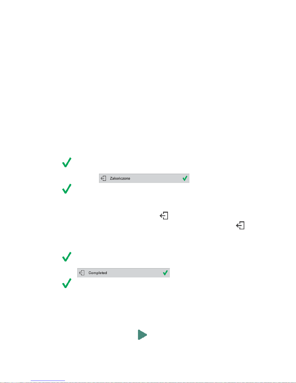
- 92 -
• boost mixture weight, weigh as much as required to provide specified weight value,
• press button to confirm, mixture dosing ends, formulation report is printed and recorded in a
database (read next section of this manual to view an example of the report), the following
message is displayed:
,
• press button in order to proceed to other opersations.
or:
• with the last ingredient dosed and weighed, press button,
• wait to see the following message: , press button
again in order to resign from boosting mixture weig ht to a specified value, if there is such a
need,
• wait to see the following message: ,
• press button to confirm, mixture dosing ends, formulation report is printed and recorded in a
database (read next section of this manual for an example of the report), the following message
is displayed:
,
• press button in order to proceed to other opersations.
PROCEDURE 2 – Prep aring formulation that is saved in the Form ulation Database. Basic option for
creating recipes.
Following the prompts:
• load container intended for the ingredients,
• go to quick access bar and press Start < > button,
• list of formulations is displayed, select the formulation that is to be carried out,
Page 93

- 93 -
• home screen is displayed, container weight is tared automatically, <Formulation> field provides
formulation name, <Target value> field provides total weight value for a selected formulation,
navigation bar with messages for ease of operation and with names of particular mixture
ingredients is shown,
At the top of information area there is a bar graph, underneath the bar graph weight value that
is to be dosed is dis played. Bar graph colour changes gradually depending on the ingredient
weight (read Dosing section for detailed description of bar graph).
• pour specified amount of ingredient no. 1,
• press < > button to confirm,
• weight of ingredient 1 is recorded into balance memory (Sum field provides weight of dosed
ingredient no.1), indication is tared,
• repeat the steps for remaining mixture ingredients,
• when dosing is completed formulation report is printed and recorded in a database (r ead next
section of this manual to vie w an example of the report), the following message is displayed:
• press button in order to proceed to other opersations,
• press button to abort formulation any time you need.
Page 94

- 94 -
PROCEDURE 3 – Preparing formulation that is saved in the Formulation Database – using multiplier
function.
Go to Formulation mode settings and set <Multiplier> parameter to <YES> value, next follow the
below procedure.
Procedure:
• With <YES> value selected, the program asks you to specify multiplier value prior to each
process start.
Following the prompts:
• load container intended for the ingredients,
• go to quick access bar and press Start < > button,
• list of formulations is displayed, select the formulation that is to be carried out,
• window with numeric keyboard is displayed, enter the multiplier value,
Page 95

- 95 -
• home screen is displayed, container weight is tared automatically, <Formulation> field provides
formulation name, <Target value> field provides total weight value for a selected formulation,
navigation bar with messages for ease of operation and with names of particular mixture
ingredients is shown,
Weight of ingredient f rom bar graph area is also multiplied by the multiplier
• now follows steps like for formulation without the multiplier.
22.5. PERFORMED FORMULATIONS REPORT
Upon each completed formulation process the program generates a report. The report is recorded in
<Formulations reports> database. Report file name contains date and time of particular process
performance.
Report example:
------------- Formulation Report ----------------
User Nowak Jan
Formulation name Test 1
Start date 2015.07.10 13:21:40
End date 2015.07.10 13:22:28
Ingredients quantity 5
Measurements quantity 5
------------------- Ingredient 1 --------------------
Name Product 01
Weight 19.994 g
------------------- Ingredient 2 --------------------
Name Product 02
Weight 49.993 g
------------------- Ingredient 3 --------------------
Name Product 03
Weight 9.999 g
------------------- Ingredient 4 --------------------
Name Product 04
Masa 1.001 g
------------------- Ingredient 5 --------------------
Name Product 05
Weight 19.995 g
Sum 100.982 g
Target value 101.000 g
Difference -0.018 g
Page 96

- 96 -
Status Completed
--------------------------------------------------------
Signature
....................................................................
Page 97

- 97 -
23. DATABASES
Balance software features the following databases < >:
Products (5 000 products)
Users (100 users)
Packaging (100 packaging types)
Customers (1 000 customers)
Formulations (100 formulations consisting of 25 ingredients maximally)
Formulations reports (500 reports)
Ambient Conditions (10 000 records)
Weighings (50 000 records)
Alibi (512 000 records)
CAUTION!
It is not possible to edit some of the databases for a balance cooperating with E2R software. Shall you
introduce any modifications on databases, use the PC software.
23.1. DATABASE CONNECTED OPERATIONS
The program enables the user with appropriate access level to carry out the following operations:
adding new record, export ing data from databases, importing data to databases, deleting one record
from the database, deleting all records from database, printing data saved in a record.
ADD NEW RECORD
Procedure:
• Enter a database and press (Add) button located in the top bar.
• Define fields for the new record (data content depends on the database).
• On returning to the databases window a new record is displayed on the list.
EXPORT
Procedure:
• Insert USB flash dri v e.
• Open the database that is to be exported.
• Press icon located in the top bar.
• The progr am automatically saves exported data to a USB flash drive file, respective prompts
are displayed for confirmation of sucsessfully completed operation.
• The name of a file depends on the database.
Database
File name and extension
Operators database
users.x2
Products database
products.x2
Packaging database
packaging.x2
Customers database
customers.x2
Formulations database
formulas.x2
Non-standard printouts
non_standard_printouts.x2
IMPORT
Procedure:
• Save the file with database content that is to be imported to a flash drive. Only files exported
from other balance that have proper names and extensions can be imported – see table above.
• Insert USB flash drive.
• Enter database that is to be imported.
• Press icon located in the top bar.
Page 98

- 98 -
• The program automatically reads the file and the data is imported to the balance. Respective
prompts are displayed for confirmation of sucsessfully completed operation.
DELETE A RECORD
Procedure:
• Press the record and hold it.
• A message: <Confirm to delete> is displayed.
• Press < > to confirm, the record is deleted from the list.
DELETE A DATABASE
Procedure:
• Enter selected database and press (Delete everything) pictogram located in the top bar.
• A message: <Confirm to delete all records> is displayed.
• Press < > to confirm, the database is deleted.
FORMULATIONS REPORTS, WEIGHING REPORTS and ALIBII cannot be imported. ALIBII
database cannot be deleted. The databases content can only be exported and saved to a flash drive.
Names of files with exported data consist of serial number and proper extension (see table below).
Database
File name and extension
Formulations Reports
123456.for
Weigh i ng Repor ts
123456.wei
Alibii
123456.ali
Files can be read using ALIBI Reader by RADWAG that can be downloaded from the website:
www.radwag.pl.
AMBIENT CONDITIONS database serves informative purposes only. Using records preview option
you can check ambient conditions and observe how they changed over time. The data saved to
records can be printed by pressing pictogram locat ed in the top bar. Records’ names contain
date and time of saving the record’s data to balance memory.
23.2. PRODUCTS
Product database stores names of all products that can be weighed, counted, controlled.
Procedure:
• Enter < Databases> submenu, press <Products> key.
• Press < Add> key for adding a new product.
• For operating an already introduced product press the product field.
List of parameters defined for a product:
1. Name
2. Code [product code]
3. EAN [EAN code for a product]
4. Mass [nominal mass/single product mass]
5. Tare [tare value, set automatically when the product is selected out of the database]
6. Min [low limit for product weighing in CHECKWEIGHING mode]
7. Max [high limit for product weighing in CHECKWEIGHING mode]
8. Tolerance [% value calculated in relation to mass, the parameter determines measuring area
for which the measurement is recognized as correct for DOSING mode.]
CAUTION!
Page 99

- 99 -
Remember to assign product to particular mode, as some of data values are adopted to the particular mode
functions, e.g. mass in <Percent Weighing> mode is accepted as reference mass, whereas mass in <Parts
Counting> mode is accepted as single part mass. When a particular product is used for different modes then its
weight, taken from product data, is associated with different data for these modes.
23.3. OPERATORS
Users database features list of operators permissioned to operate the balance.
List of parameters defined for a user:
1. Name
2. Code
3. Password
4. Permissions level
5. Language
Adding a new operator – operation to be carried out by an Administrator exclusively. In order t o add
a new user:
• enter Operators menu and press < Add> key,
• fill in the new record fields,
• return to window displaying operators list, the new record has been added.
Editing information relating to an operator:
• press selected operator name,
• the selected operator parameters are displayed,
• select data that is to be modified, introduce changes.
Deleting an operator - operation to be carried out by an Administrat or exclusively. In order to delete
a user:
• press and hold selected user,
• message <Confirm to delete> is displayed,
• press < > key,
• selected user is deleted.
23.4. PACKAGING
List of used packaging with parameters such as name, code and weight value specified. When
carrying out weighing process, upon selection of particular packaging, a respective tare value is
operated automatically. The tare value is displayed with minus sign.
Procedure:
• Enter < Databases> menu, press <Packaging> key,
• Press < Add> key for adding new packaging,
• For operating already introduced packaging press the packaging field, fill in respective data.
List of parameters defined for packaging:
1. Name
2. Code [internal code providing packaging identification]
3. Tare [packaging weight]
Page 100

- 100 -
23.5. CUSTOMERS
Customers database features a list of names of customers for whom the measurements are carried
out.
Procedure:
• Enter < Databases> menu, press <Customers> key,
• Press < Add> button for adding a new customer,
• For operating an already introduced customer, press the customer field, fill in respective data.
List of parameters defined for a customer:
1. Name
2. Code [internal code providing customer identification]
3. VAT no. [tax identification no.]
4. Address
5. Postal code
6. City
23.6. FORMULATIONS
Formulations database contains all added formulations. They can be carried out automatically.
Procedure:
• Enter < Databases> submenu, press <Formulations> key,
• Press < Add> button to design a new formulation, or
• Select already existing formulation button and press it,
List of parameters defined for a formulation:
1. Name
2. Code
3. Ingredients
4. Target value
23.7. FORMULATIONS REPORTS
Reports on formulations database stores information on carried out formulations. Each report can be
previewed and printed.
Procedure:
• Enter < Databases> submenu, press <Formulation Reports> key,
• Select particular report button out of the list, use scroll buttons to find the report you need,
• Report’s name consists of date and time of its creation, e.g.: 2011.10.12 15:12:15.
Information provided by the Formulation Report:
• User
• Formulation
• Start date
• End date
• Ingredients quantity
• Measurements
• Sum
• Target value
• Difference
 Loading...