

Page 1

WLC
USER MANUAL
WLC/A1/C/2 Precision Scale
WLC/A2/C/2 Precision Scale
WLC/A2 Precision Scale
ITKU-105-08-11-18-EN
Page 2

2
NOVEMBER 2018
Page 3

3
CONTENTS
1. GENERAL INFORMATION............................................................................................................................5
2. PRECAUTIONS ............................................................................................................................................. 5
2.1. Operation ................................................................................................................................................ 5
2.2. Battery Power Supply.............................................................................................................................. 5
2.3. Operation under Conditions Difficult due to Electrostatics ....................................................................... 6
3. WARRANTY CONDITIONS........................................................................................................................... 6
4. DESIGN .........................................................................................................................................................7
4.1. Dimensions ............................................................................................................................................. 7
4.2. Connectors Arrangement ........................................................................................................................ 8
4.3. Pins Overview ......................................................................................................................................... 8
5. UNPACKING AND INSTALLATION.............................................................................................................. 9
5.1. Under-Pan Weighing ............................................................................................................................... 9
6. START-UP AND OPERATION.....................................................................................................................10
6.1. Levelling................................................................................................................................................ 10
6.2. Connecting the Scale to the Mains........................................................................................................ 10
6.3. Warm-Up Time...................................................................................................................................... 11
6.4. Battery Charge Status ........................................................................................................................... 11
6.5. Battery Charge Status Check ................................................................................................................ 12
7. MAINTENANCE ACTIVITIES ...................................................................................................................... 12
7.1. Cleaning ABS Components................................................................................................................... 12
7.2. Cleaning Glass Components................................................................................................................. 12
7.3. Cleaning Stainless Steel Components................................................................................................... 13
7.4. Cleaning Powder-Coated Components ................................................................................................. 13
7.5. Cleaning Aluminium Components ......................................................................................................... 13
8. OPERATION PANEL................................................................................................................................... 14
9. KEYS...........................................................................................................................................................14
10. PROGRAM STRUCTURE.......................................................................................................................... 15
10.1. Function Groups.................................................................................................................................. 15
10.2. Operating the Menu ............................................................................................................................ 16
10.3. Return to the Weighing Mode.............................................................................................................. 16
11. WEIGHING OPERATION...........................................................................................................................16
11.1. Good Weighing Practice...................................................................................................................... 17
11.2. Zeroing................................................................................................................................................ 17
11.3. Taring.................................................................................................................................................. 18
11.4. Entering Tare Value Manually ............................................................................................................. 18
11.5. Dual Range Devices............................................................................................................................ 18
11.6. Units.................................................................................................................................................... 19
11.6.1. Start Unit .................................................................................................................................. 19
11.6.2. Temporary Unit......................................................................................................................... 20
12. ADJUSTMENT...........................................................................................................................................20
12.1. External Adjustment ............................................................................................................................ 21
12.2. User Adjustment.................................................................................................................................. 22
12.3. Manual Internal Adjustment................................................................................................................. 22
12.4. Automatic Internal Adjustment............................................................................................................. 23
12.5. Automatic Internal Adjustment Time.................................................................................................... 24
12.6. Adjustment Test .................................................................................................................................. 24
12.7. Adjustment Report .............................................................................................................................. 25
13. SCALE PARAMETERS............................................................................................................................. 25
13.1. Filter.................................................................................................................................................... 25
13.2. Value Release..................................................................................................................................... 25
13.3. Ambient Conditions............................................................................................................................. 26
13.4. Autozero Function............................................................................................................................... 26
13.5. Tare Function...................................................................................................................................... 26
13.6. Tare: Enter Mode ................................................................................................................................ 27
13.7. Tare: Values Memory.......................................................................................................................... 27
13.7.1. Entering Tare Value to the Weighing Device Memory .............................................................. 27
13.7.2. Selecting Tare Value from the Weighing Device Memory......................................................... 28
13.8. Last Digit............................................................................................................................................. 28
14. COMMUNICATION....................................................................................................................................29
14.1. RS232 (1) Port Settings ...................................................................................................................... 29
14.2. RS232 (2) Port Settings ...................................................................................................................... 29
14.3. USB A Port.......................................................................................................................................... 29
Page 4

4
14.4. USB B Port.......................................................................................................................................... 30
15. PERIPHERAL DEVICES............................................................................................................................32
15.1. Computer ............................................................................................................................................ 32
15.1.1. Computer Port.......................................................................................................................... 32
15.1.2. Continuous Transmission......................................................................................................... 32
15.1.3. Printout Interval for Continuous Transmission .......................................................................... 33
15.2. Printer ................................................................................................................................................. 33
15.2.1. Printer Port ............................................................................................................................... 33
15.3. Additional Display................................................................................................................................ 33
15.3.1. Additional Display Port ............................................................................................................. 34
16. PRINTOUTS .............................................................................................................................................. 34
16.1. Adjustment Report .............................................................................................................................. 34
16.2. GLP Printout ....................................................................................................................................... 35
17. MISCELLANEOUS PARAMETERS...........................................................................................................36
17.1. Backlight ............................................................................................................................................. 36
17.2. 'Beep' Sound....................................................................................................................................... 36
17.3. Automatic Shutdown ........................................................................................................................... 36
17.4. Date and Time..................................................................................................................................... 37
17.5. Default User Settings .......................................................................................................................... 37
18. SCALE DATA............................................................................................................................................ 38
19. WORKING MODES – General Information.............................................................................................. 38
19.1. Running Working Mode....................................................................................................................... 38
19.2. Working Modes Local Settings............................................................................................................ 39
19.2.1. Working Mode Accessibility...................................................................................................... 39
19.2.2. Save Mode ............................................................................................................................... 39
19.2.3. Automatic Printout Time Interval............................................................................................... 40
19.2.4. Lo Threshold ............................................................................................................................ 40
20. WORKING MODE – WEIGHING................................................................................................................41
20.1. Local Settings...................................................................................................................................... 41
21. WORKING MODE – PAR TS COUNTING.................................................................................................. 41
21.1. Local Settings...................................................................................................................................... 41
21.1.1. Selecting Operation Mode ........................................................................................................ 41
21.2. Setting Sample Mass by Entering Mass of a Single Part..................................................................... 42
21.3. Setting Sample Mass by Determining Mass of a Single Part ............................................................... 42
22. WORKING MODE – +/- CONTROL...........................................................................................................43
22.1. Local Settings...................................................................................................................................... 43
22.2. Declaring Checkweighing Thresholds ................................................................................................. 43
23. WORKING MODE – PERCENT WEIGHING.............................................................................................. 44
23.1. Local Settings...................................................................................................................................... 44
23.1.1. Selecting Operation Mode ........................................................................................................ 44
23.2. Reference Sample Mass Determined by Weighing ............................................................................. 45
23.3. Reference Sample Mass Determined by Entering the Mass Value...................................................... 45
24. WORKING MODE – PEA K HOLD.............................................................................................................45
24.1. Local Settings...................................................................................................................................... 45
24.2. Peak Hold Operation........................................................................................................................... 46
25. WORKING MODE – TOTALIZING............................................................................................................. 46
25.1. Local Settings...................................................................................................................................... 46
25.2. Totalizing Operation............................................................................................................................ 46
26. WORKING MODE – ANIMAL WEIGHING................................................................................................. 47
26.1. Local Settings...................................................................................................................................... 48
26.2. Animal Weighing Operation................................................................................................................. 48
27. IMPORT / EXPORT....................................................................................................................................48
27.1. Weighing Records Export.................................................................................................................... 49
27.2. ALIBI Weighings Export ...................................................................................................................... 49
27.3. Parameters Export / Import ................................................................................................................. 49
28. INPUTS / OUTPUTS..................................................................................................................................50
28.1. Inputs / Outputs Parameters................................................................................................................ 50
28.2. Inputs Setup........................................................................................................................................ 50
28.3. Outputs Setup..................................................................................................................................... 51
29. DIAGRAMS OF CONNECTION CABLES ................................................................................................. 52
30. TROUBLESHOOTING...............................................................................................................................53
31. ERROR MESSAGES................................................................................................................................. 53
Page 5
5
1. GENERAL INFORMATION
WLC/A1, WLC/A2 precision scales enable fast and accurate mass
measurements under laboratory and industrial conditions. The devices are
equipped with an internal battery which allows their operation in places where
there is no access to the mains. The WLC series features a stainless steel
weighing pan, and a backlit LCD guaranteeing clear weighing result
presentation.
WLC/A1, WLC/A2 precision scales are equipped with the following interfaces:
2 x RS232, USB type A, and USB type B. The interfaces enable cooperation
between the scale and peripheral devices (e.g. printer, computer, USB flash
drive).
2. PRECAUTIONS
2.1. Operation
A. Prior the first use, carefully read this User Manual. Use the device only
as intended.
B. Indicators to be decommissioned must be decommissioned in accordance
with valid legal regulations.
2.2. Battery Power Supply
WLC/A1, WLC/A2 series scales are devices intended to be supplied by SLA
battery (sealed lead acid) of 3 - 4 Ah capacity.
Do not let battery discharge in case of prolonged storage
of the device in low temperature.
Accumulators do not belong to regular household waste.
The European legislation requires discharged accumulators
to be collected and disposed separately from other
communal waste with the aim of being recycled. Dear user,
you are obliged to dispose of the worn out batteries as
regulated.
Notice: Symbols on batteries identify harmful compounds:
Pb = lead, Cd = cadmium, Hg = mercury.
A worn out battery can be replaced only by the manufacturer
or by the authorized service.
Page 6

6
2.3. Operation under Conditions Difficult due to Electrostatics
If the device is to be operated in a place characterized with conditions that are
difficult due to electrostatics (e.g. printing house, packing centre, etc.),
you must connect it to the earth wire. To enable this, the device features
functional earthing terminal, marked with
symbol.
3. WARRANTY CONDITIONS
A. RADWAG feels obliged to repair or exchange all elements that appear
to be faulty by production or by construction.
B. Defining defects of unclear origin and means of their elimination can only
be realized with assistance of manufacturer and user representatives.
C. RADWAG does not bear any responsibility for damage or losses
resulting from unauthorized or inadequate performing of production
or service processes.
D. The warranty does not cover:
• mechanical damage caused by product exploitation other than
intended, damage of thermal and chemical origin, damage caused by
lightning, overvoltage in the power network or other random event,
• inappropriate cleaning habits.
E. Loss of warranty takes place if:
• a repair is carried out outside RADWAG authorized service point,
• service claims intrusion into mechanical or electronic construction
by unauthorized people,
• the device does not bear company security stickers.
F. Warranty conditions outline the warranty period for rechargeable
batteries attached to the device for 12 months.
G. For detailed warranty conditions read the warranty certificate.
H. Contact with the central authorized service: +48 48 384 88 00 ext. 106
and 107.
Page 7
7
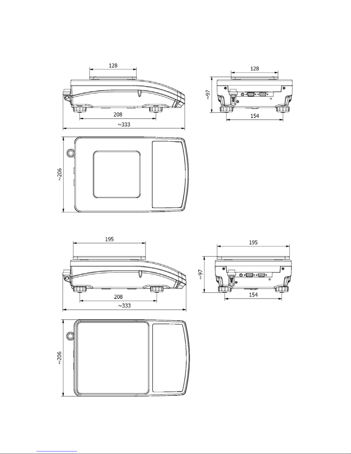
4. DESIGN
4.1. Dimensions
Figure 1a. WLC/A1 precision scale
Figure 1b. WLC/A2 precision scale
Page 8
8
4.2. Connectors Arrangement
Figure 2. Connectors view
1- power supply socket 12 VDC
2- RS232 (1) connector
3- RS232 (2) connector
4- USB A "host"
5- USB B "device"
4.3. Pins Overview
Pin2 – RxD
Pin3 – TxD
Pin4 – 5 VDC
Pin5 – GND
RS232 (1) connector
DB9/M (male)
Pin1 - GNDWE
Pin2 - OUT1
Pin3 - OUT2
Pin4 - COMM
Pin6 - IN4
Pin7 - IN3
Pin8 - TxD2
Pin9 - 5 VDC
Pin10 - GNDRS
Pin11 - IN2
Pin12 - IN1
Pin13 - RxD2
Pin14 - OUT4
Pin15 - OUT3
IN/OUT, RS232 (2) connector
DSUB15/F (female)
Page 9

9
5. UNPACKING AND INSTALLATION
• Unpack the device and place it on a flat and even surface. Keep it far
away from any sources of heat.
• Install the weighing pan, follow the below figures:
WLC/A1 precision scale WLC/A2 precision scale
5.1. Under-Pan Weighing
The WLC/A1, WLC/A2 scales enable weighing loads below scale (so called
under-pan weighing). This is an alternative for loads of non-standard
dimensions and shapes, and for loads generating magnetic field.
Preparing the scale for the under-pan weighing:
1. Unpack the scale, assembly it
following section 5 of this user
manual.
-
2. Put the scale right side down.
Page 10
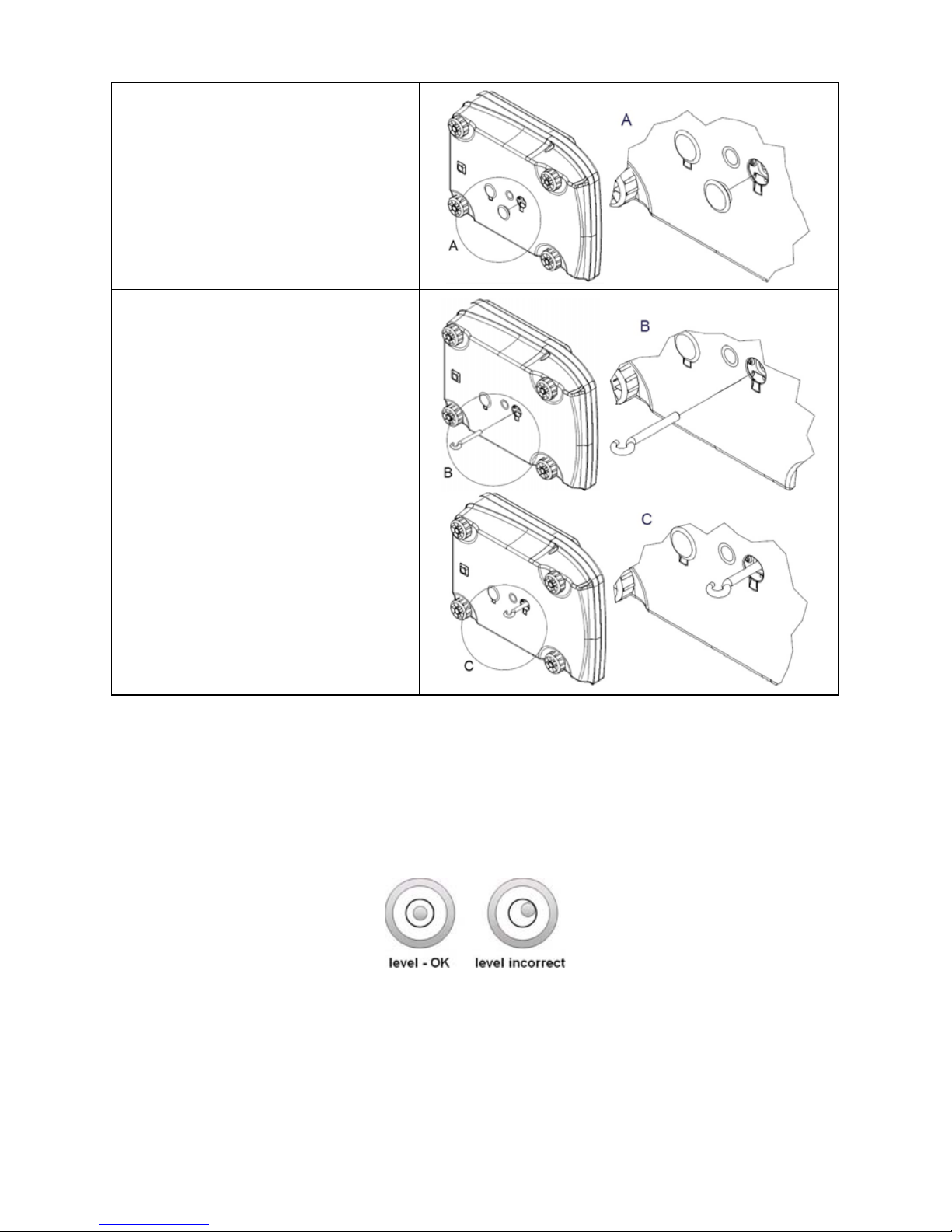
10
3. Remove the hole plug.
4. Mount the hook and put the
scale bottom side down.
6. START-UP AND OPERATION
6.1. Levelling
To level the weighing instrument turn its feet. Keep turning the feet until the air
bubble takes central position:
6.2. Connecting the Scale to the Mains
The weighing device can be connected to the mains only with a power supply
that comes standard with the particular model.
Page 11
11
Nominal voltage of the power supply (specified on the power supply data plate)
has to be compatible with the mains nominal voltage.
Procedure:
• Connect the power supply to the mains. Plug it to the power supply socket
(back side of the scale housing).
• Press
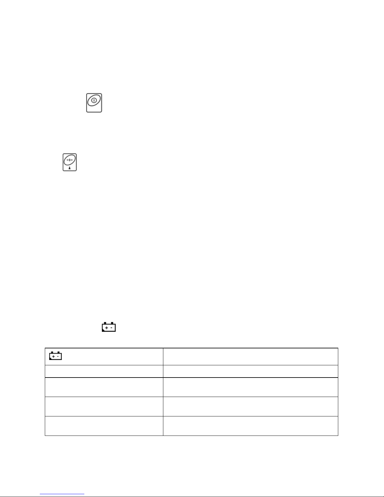
key. The key is also used to switch the scale on/off.
• Display test proceeds (all symbols are backlit for a moment), program
name and number is displayed first, ZERO indication with reading unit
next (displayed reading unit is conditioned by scale type).
• In case the weighing result is not zero after indication stabilisation, press
key.
6.3. Warm-Up Time
• For correct scale operation, the workroom temperature must range
between +15°C ÷ +30°C.
• It takes 30 minutes for the device to warm up.
• During the thermal stabilization, the indications on the screen can change.
• If you want to carry out adjustment operation, make sure that your device
is thermally stable.
• Temperature and humidity variations during operation may cause
indication errors. To remove the indication errors perform user adjustment.
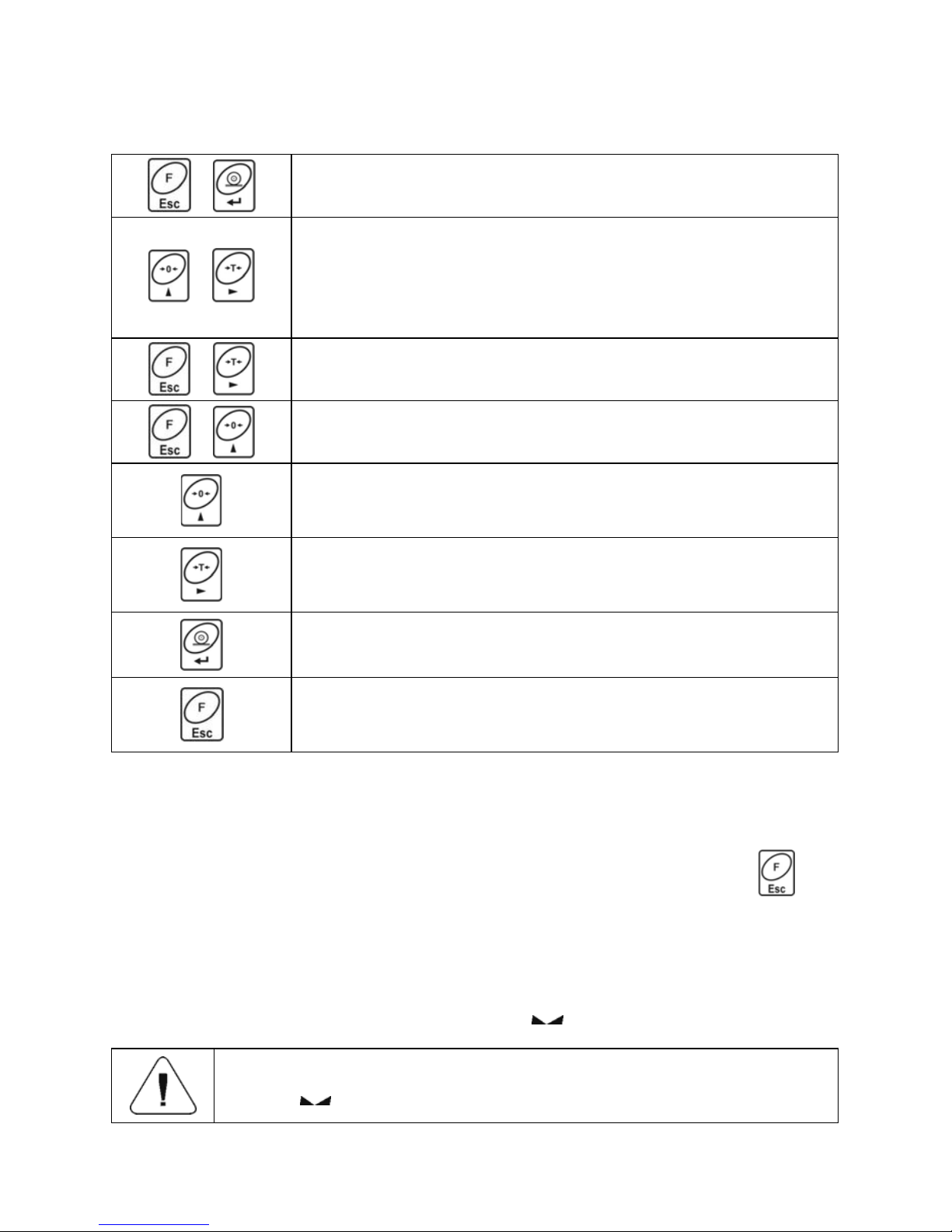
6.4. Battery Charge Status
The scale of standard design is equipped with an internal battery. Battery state
is signalled by
pictogram, the pictogram is displayed in the top bar of the
display.
pictogram display mode
Meaning
No pictogram Battery charged. Regular scale operation.
Pictogram displayed continuously
Too low battery charge (the scale is about to shut
down). Charge the battery immediately.
Blinking pictogram, blink frequency:
ca. 1 s
Battery charge in progress. The device is connected
to the power supply charging the battery.
Blinking pictogram, blink frequency:
ca. 0.5 s
Battery error. Battery is damaged.
Page 12

12
6.5. Battery Charge Status Check
• Press and keys combination.
• Battery charge state, given in %, is displayed for 2 s.
• Next, home screen is displayed automatically.
7. MAINTENANCE ACTIVITIES
In order to ensure safety in the course of cleaning, it is necessary to disconnect
the device from the mains. With this condition met, uninstall the weighing pan
and other detachable components.
Cleaning the weighing pan while still installed may cause
damage of the measuring system.
7.1. Cleaning ABS Components
To clean dry surfaces and avoid smudging, use clean non-colouring cloths
made of cellulose or cotton. You can use a solution of water and detergent
(soap, dishwashing detergent, glass cleaner). Gently rub the cleaned surface
and let it dry. Repeat cleaning process if needed.
In the case of hard to remove contamination, e.g. residues of adhesive, rubber,
resin, polyurethane foam etc., you can use a special cleaning agents based on
a mixture of aliphatic hydrocarbons that do not dissolve plastics. Before using
the cleanser for all surfaces we recommend carrying out tests. Do not use
cleansers containing abrasive substances.
7.2. Cleaning Glass Components
Select dissolvent depending on a dirt. Never soak the glass panes in alkaline
solutions since they interact with glass and may cause damage. Do not use
cleansers containing abrasive substances.
For organic dirt use acetone first, next use water or detergent. For other than
organic dirt use diluted acid solutions (soluble salts of hydrochloric or nitric
acid) or base solutions (ammonium or sodium base). To remove ACIDS use
protophilic solvent (sodium carbonate), to remove BASE use protogenic solvent
(mineral acid of various concentration).
In case of heavy contamination use brush and detergent, nevertheless avoid
detergents containing large and hard molecules which could potentially scratch
glass panes.
Page 13

13
At the end of the cleaning process rinse the pane using distilled water. Use soft
brush with wooden or plastic handle exclusively in order to avoid risk
of scratches. Do not use wire brush. Rinsing is a necessary cleaning process
stage allowing to remove remaining soap, detergents and other cleansers from
the panes prior their reinstallation. After preliminary cleaning process stage,
rinse the pane using running water first, distilled next.
Avoid drying the panes either using paper towel or forced air circulation since
some fibres, grains or contamination of other type could permeate into the
panes thus causing weighing errors. We do not recommend using driers when
drying measuring glass tools. It is a frequent treatment to leave glass
components on a rack to dry.
7.3. Cleaning Stainless Steel Components
Avoid using cleansers containing any corrosive chemicals, e.g. bleach
(including chlorine). Do not use cleansers containing abrasive substances.
Always remove the dirt using microfiber cloth to avoid damage of protective
coating.
In case of a daily maintenance:
1. Remove the dirt using cloth dipped in warm water.
2. For best results, add a little bit of dishwashing detergent.
7.4. Cleaning Powder-Coated Components
For preliminary cleaning process stage you need running water or wet sponge
featuring large holes, this will help you to remove loose, heavy dirt. Do not use
cleansers containing abrasive substances.
Next, using cloth and cleanser-water solution (soap, dishwashing liquid) gently
rub the cleaned surface.
Avoid using cleanser without water since it may result with damage of the
cleaned surface, please mind that large amount of water mixed with cleanser
is a must.
7.5. Cleaning Aluminium Components
While cleaning aluminium components use products acid by nature, e.g. spirit
vinegar, lemon. Do not use cleansers containing abrasive substances. Avoid
using hard brush, this may cause scratches. It is recommended to use
microfibre cloth.
While polishing the surface use circular movements. Use clean, dry cloth
to make the surface shine.
Page 14
14
8. OPERATION PANEL
Operation panel of WLC/A2 precision scale
Operation panel of WLC/A1/C/2, WLC/A2/C/2 precision scales
9. KEYS
Press to switch the weighing device on/off – hold the key for about
1 second.
Function key, press to change the working mode.
Press to send the weighing result to a printer or computer.
Press to zero the scale.
Page 15

15
Press to tare the scale.
Press to perform internal adjustment manually (WLC/A1/C/2,
WLC/A2/C/2 scales).
Upon pressing
+ keys combination, functions
of given keys change. Detailed information concerning use
of
+ keys combination is to be found further down
this manual.
10. PROGRAM STRUCTURE
Program menu is divided into function groups. Function group is a group
of interrelated parameters.
10.1. Function Groups
Function group
number
Function group
name
Description
P1 CAL User adjustment
P2 rEAd Readout parameters
P3 Func Working modes
P4 Conn Communication
P5 ducE Peripheral devices
P6 Prnt Printouts
P7 Othr Operation-related functions
P8 InFo Scale data
P9 Unit Units
IO - Inputs / Outputs
IE - Import / Export
Page 16
16
10.2. Operating the Menu
In order to navigate the program menu use the operation panel.
+
Press to enter the main menu.
+
Press to:
• enter tare manually.
• enter tare from tare database,
• change value by 1 digit up,
• scroll the menu up.
+
Press to check battery/accumulator state.
+
Press to view date/time.
Press to:
• scroll the menu down,
• change current parameter value.
Press to:
• enter given submenu,
• modify given parameter.
Press to confirm modification.
Press to:
• exit, function remains unmodified,
• move one menu level up.
10.3. Return to the Weighing Mode
Introduced menu modifications are automatically saved to scale memory upon
return to the home screen. To return to the home screen press
key
repeatedly.
11. WEIGHING OPERATION
Load the weighing pan. Read the result when stability marker is displayed.
Only stable weighing results can be recorded (stability
marker
).
Page 17

17
11.1. Good Weighing Practice
To assure long-term operation and correct mass measurements, follow the
rules presented below:
Load the weighing pan steadily
avoiding mechanical shocks.
Place weighed loads centrally on the
weighing pan (eccentricity errors are
specified by EN 45501 standard, point
3.6.2.).
Do not apply concentrated force (total
load in one point).
Avoid side loading, in particular side
shocks.
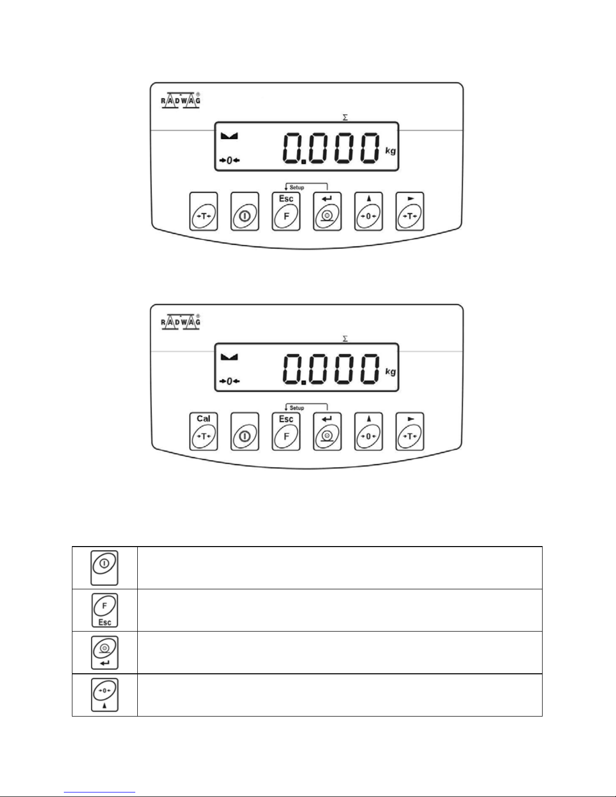
11.2. Zeroing
To zero mass indication press
key. Zero indication and the following
pictograms are displayed:
and . The instrument can be zeroed only
when the indication is stable.
Indication can be zeroed only within ±2% range of maximum
capacity. If the zeroed value is greater than ±2% of the
maximum capacity, then the software displays message
<Err2>, and short sound signal is heard.
Page 18

18
11.3. Taring
To determine net weight value, load the weighing pan with a packaging, wait
for a stable indication and press
key. Zero indication and the following
pictograms are displayed: Net and
. The weighing device has been tared.
Upon loading, net mass is displayed.
Taring can be carried out repeatedly within the whole weighing range.
Remember not to exceed the maximum capacity, i.e. sum of tare weight value
and load weight value must be lower than the maximum capacity value. Upon
unloading the weighing pan, the sum of tared masses with minus sign
is displayed.
It is impossible to tare zero or negative values. When you
tare zero or negative values, message <Err3> is displayed,
short sound signal is heard.
11.4. Entering Tare Value Manually
• Press and keys combination, tare value edit box is displayed.
• Enter tare value, to do it press
and keys:
Press to select digit that is to be edited.
Press to set digit value, 0 - 9 .
• Press key to confirm, the scale returns to the weighing mode,
modified tare value with '–' sign is displayed.
• You can enter tare value at any time during the weighing operation.
11.5. Dual Range Devices
N/A in case of single range scales
Switching from weighing with the accuracy of the I weighing range to weighing
with the accuracy of the II weighing range takes place automatically upon
exceeding Max of the I weighing range. Upon switching to weighing with the
accuracy of the II weighing range, respective pictogram/marker
is displayed in the top left hand corner.
Page 19

19
To return to weighing with accuracy of the I weighing range:
• Take the load off the weighing pan.
• As the indication returns to zero and when symbols
and are
displayed, press
button.
• II weighing range pictogram/marker gets blank, the scale returns
to weighings with the accuracy of the I weighing range.
11.6. Units
<P9.Unit> parameter group enables change of start unit and temporary unit.
Unit change can be performed in the course of weighing or during operation
of other modes. 'Parts counting' and 'Percent weighing' modes are exceptions.
11.6.1. Start Unit
Parameter for setting unit that is displayed and used after device start-up.
Procedure:
• Enter <P9.Unit / 9.1.UnSt> submenu.
• Press
key, available units are displayed successively one by one.
Options in case when the main unit is [kg]:
• kg (kilogram),
• g (gram),
• lb (pound)*,
• N (Newton).
*) – unit disabled for verified weighing devices.
Options in case when the main unit is [g]:
• g (gram),
• kg (kilogram),
• ct (carat),
• lb (pound)*.
*) – unit disabled for verified weighing devices.
• Select start unit and press key, next go back to the home screen,
to do it press
key.
• Upon next start-up the scale runs with set start unit.
Page 20

20
11.6.2. Temporary Unit
Temporary unit runs from the moment it is set to the scale shut-down and
restart.
Procedure:
• Enter <P9.Unit / 9.2.Unin> submenu.
• Press
key, available units are displayed successively one by one.
Options in case when the main unit is [kg]:
• kg (kilogram),
• g (gram),
• lb (pound)*,
• N (Newton).
*) – unit disabled for verified weighing devices.
Options in case when the main unit is [g]:
• g (gram),
• kg (kilogram),
• ct (carat),
• lb (pound)*.
*) – unit disabled for verified weighing devices.
• Select temporary unit and press key, next go back to the home
screen.
12. ADJUSTMENT
In order to ensure the highest weighing accuracy, it is recommended
to periodically introduce corrective factor of indications to scale memory,
the said factor must be referred to a reference weight. This is so called
adjustment. Adjustment has to be carried out:
• prior weighing,
• if long breaks between successive measuring series occur,
• if the ambient temperature has changed dynamically,
• if the scale has been relocated.
Page 21

21
Adjustment types:
• external adjustment performed using an external weight of declared mass,
i.e. mass that cannot be modified,
• user adjustment performed using an external weight of mass of any value
comprised within the weighing range, however not lower than 30% of the
maximum capacity value.
• automatic internal adjustment,
• manual internal adjustment.
In case of verified scales only two adjustment types are
available: automatic internal adjustment and manual internal
adjustment. Remember to carry out the adjustment process
when there is no load on the pan! When the weighing pan
is loaded with too heavy load, message <Err4> is displayed.
In such case, unload the weighing pan and repeat the
adjustment. Adjustment process can be aborted if necessary
at any time, to do it press
key.
12.1. External Adjustment
option available for non-verified scales exclusively
External adjustment must be carried out using an external adjustment weight
of class F
1
, adjustment weight mass is conditioned by scale type and maximum
capacity.
Procedure:
• Enter <P1.CAL / 1.1.CA-E> submenu, text <UnLoAd> (remove weight)
is displayed.
• Remove the load from the weighing pan and press
key.
• Mass of an empty weighing pan is determined, this is signalled with
display of 'dash', < - >. Next, text <LoAd> (load weight) and mass
value that is to be loaded, e.g. 2000 g (conditioned by scale type), are
displayed.
• Load the weighing pan with weight of specified mass value and press
key
.
• Weight mass is determined, this is signalled with display of 'dash',
< - >. Next, text <UnLoAd> (remove weight) is displayed.
• Remove the load form the weighing pan, <1.1.CA-E> submenu
is displayed.
Page 22

22
12.2. User Adjustment
option available for non-verified scales exclusively
External adjustment must be carried out using an external adjustment weight
of class F
1
, and of mass value ≥ 30% of the maximum capacity value.
Procedure:
• Enter <P1.CAL / 1.2.CA-u> submenu, edit box for declaring weight mass
is displayed (the mass value must be ≥ 30% of the maximum capacity
value).
• Enter weight mass value and press
key to confirm, text <UnLoAd>
(remove weight) is displayed.
• Remove the load from the weighing pan and press
key.
• Mass of an empty weighing pan is determined, this is signalled with
display of 'dash', < - >. Next, text <LoAd> (load weight) and mass
value that is to be loaded, e.g. 2000g, are displayed.
• Load the weighing pan with weight of specified mass value and press
key
.
• Weight mass is determined, this is signalled with display of 'dash',
< - >. Next, text <UnLoAd> (remove weight) is displayed.
• Remove the load from the weighing pan, <1.2.CA-u> submenu
is displayed.
12.3. Manual Internal Adjustment
Manual internal adjustment is carried out using an in-built internal weight.
Adjustment requires stable ambient conditions (no air drafts,
ground vibrations, etc.). Adjustment must be carried out
when the weighing pan is unloaded.
Procedure:
• In the course of regular scale operation press
key, adjustment
process is run automatically.
• Adjustment process, when in progress, is signalled with display of 'dash',
< - >.
• Upon completed adjustment process, the scale automatically returns
to the weighing mode.
Page 23

23
12.4. Automatic Internal Adjustment
Automatic internal adjustment is triggered:
• after connection of the scale to the mains,
• when temperature variation occurrs,
• after passage of specified time interval.
In case of an automatic internal adjustment it is necessary to declare condition
that is to trigger the automatic adjustment. To declare the condition,
go to <1.5.ACL> parameter:
nonE
Adjustment disabled.
tnnP
Adjustment triggered by temperature variation greater than 3°C.
tinnE
Adjustment carried out in specified time intervals. For non-verified scales it
is possible to set the time interval between successive automatic
adjustment processes (read section 12.5 of this manual). For verified
scales the time interval is 12 hours.
botH
Adjustment triggered by both time and temperature.
Adjustment upon connection of the scale to the mains
• Upon completed start-up procedure, scale stability conditions regarding
adjustment are checked, the internal adjustment is triggered automatically.
• Adjustment process, when in progress, is signalled with display of 'dash',
< - >.
• Upon completed adjustment process, the scale automatically returns
to the weighing mode.
Adjustment upon temperature change
• The scale is equipped with precise system monitoring temperature
variation and registering temperature value for each completed adjustment
process.
• Adjustment process is triggered automatically at the moment when
temperature measured by the scale changes by more than 3°C.
• Right before the adjustment process, scale stability conditions are
checked.
• Adjustment process, when in progress, is signalled with display of 'dash',
< - >.
• Upon completed adjustment process, the scale automatically returns
to the weighing mode.
Page 24

24
Adjustment upon passage of specified time interval
• The scale is equipped with RTC, due to this time of each completed
process is registered.
• Adjustment process is triggered automatically after passage of particular
time interval, set in <1.6.CAC> parameter.
• Adjustment process, when in progress, is signalled with display of 'dash',
< - >.
• Upon completed adjustment process, the scale automatically returns
to the weighing mode.
12.5. Automatic Internal Adjustment Time
option available for non-verified scales exclusively
Parameter determining time interval between successive automatic internal
adjustments. The time interval is declared in hours and ranges between 0.5 [h]
and 12 [h].
Procedure:
• Enter <P1.CAL / 1.6.CAC> submenu.
• Press
key, available values, given in hours, are displayed
successively one by one:
Available values: 05 H, 1 H, 2 H, 3 H, 4 H, 5 H, 6 H, 7 H, 8 H, 9 H, 10 H, 11 H,
12 H.
12.6. Adjustment Test
Adjustment test function enables comparison of the internal adjustment results
with the value recorded in factory parameters. Such comparison is used for
determining drift of scale sensitivity over time.
Procedure:
• Enter <P1.CAL / 1.4.AtS> submenu, internal adjustment process starts
automatically.
• Adjustment process, when in progress, is signalled with display of <CAL>
text.
• Upon completed adjustment process, <1.4.CAtS> parameter is displayed
automatically.
Page 25

25
12.7. Adjustment Report
Adjustment report, and adjustment test report are both automatically printed
(using scale-connected printer) at the end of each adjustment process.
To declare report content go to <P6.1.CrEP> submenu. For detailed
information concerning report content read later sections of this manual.
13. SCALE PARAMETERS
Scale parameters are set to adjust the weighing device to ambient conditions
(filters) or individual needs (autozero on/off, tare values memory). These
parameters are to be found in <P2.rEAd> submenu. <P2.rEAd> submenu
comprises functions allowing you to adjust your weighing device to ambient
conditions of given workstation.
13.1. Filter
• Enter <P2.rEAd / 2.1.FiL> submenu.
• Press
key, filter values are displayed successively one by one:
1 - Fast, 2 - Average, 3 – Slow.
• Set respective value and press
key to confirm, next go to the home
screen.
The higher filter value, the longer the weighing takes.
13.2. Value Release
Enter this parameter to adjust rate of stabilisation of the measurement result.
Depending on the selected option, weighing time is either shorter or longer.
Procedure:
• Enter <P2.rEAd / 2.2.APPr> submenu.
• Press
key, available values are displayed successively one by one:
F_P - fast and reliable, PrEc – reliable, FASt – fast.
• Press
key to confirm, next go to the home screen.
Page 26

26
13.3. Ambient Conditions
Parameter relating to ambient and environmental conditions of the workstation.
Enter this parameter and set 'nStAb' value if the ambient conditions are
unfavourable (air drafts, vibrations).
Procedure:
• Enter <P2.rEAd / 2.3.Enut> submenu.
• Press
key, parameter values are displayed successively one by
one: nStAb – unstable, StAb – stable.
• Press
key to confirm, next go to the home screen.
13.4. Autozero Function
'Autozero' function has been designed to enable automatic control and
correction of zero indication. This guarantees precise weighing results.
There are, however, some cases when this function can be a disturbing factor
for the measuring process, e.g. very slow placing of a load on the weighing pan
(load adding, e.g. pouring, filling). In such case, it is recommended to disable
the function.
Procedure:
• Enter <P2.rEAd / 2.4.Aut> submenu.
• Press
key, parameter values are displayed successively one by one:
YES – autozero function enabled, no – autozero function disabled.
• Press
key to confirm, next go to the home screen.
13.5. Tare Function
'Tare' function has been designed to enable setup of appropriate parameters
for tare operation.
Procedure:
• Enter <P2.rEAd / 2.5.tArE> submenu.
• Press
key, available values are displayed successively one by one:
Page 27

27
no
Regular tare mode. Select this parameter to make the scale overwrite
the set (selected) tare value with the most recently entered one.
tArF
Select this parameter to make the scale store the latest tare value
in memory. The latest tare value is displayed after scale restart.
AtAr
Automatic tare mode.
EAcH
Select this parameter to make the scale automatically tare each accepted
measurement.
• Press key to confirm, next go to the home screen.
13.6. Tare: Enter Mode
The tare is entered using
+ keys combination from the home screen
level. There are two enter modes.
Procedure:
• Enter <P2.rEAd / 2.6.ttr> submenu.
• Press
key, parameter values are displayed successively one by one:
tArEH
Select to enter tare value manually by means of + keys
combination.
tArnn
Select to enter tare value that is stored in scale memory, use
+
keys combination.
• Press key to confirm, next go to the home screen.
13.7. Tare: Values Memory
It is possible to store 10 tare values in scale memory.
13.7.1. Entering Tare Value to the Weighing Device Memory
• Enter <P2.rEAd / 2.7.tArn> submenu, name of tare no. 1 from tares
database is displayed (<tArE 0>), to select a different record press
key.
Page 28

28
• Select respective entry and press key, tare value edit box is
displayed.
• Enter tare value, to do it press
and keys:
Press to select digit that is to be edited.
Press to set digit value, 0 - 9 .
• Press key to confirm, <tArE 0> window is displayed.
• Now press
key to go to the home screen.
13.7.2. Selecting Tare Value from the Weighing Device Memory
• Enter <P2.rEAd / 2.7.tArn> submenu, name of tare no. 1 from tares
database is displayed (<tArE 0>), to select a different record press
key.
• To set the selected tare press
key.
• The set tare value is displayed with minus sign, Net symbol is shown in
the upper-left corner of the screen:
The tare value acquired from the weighing device memory is
not remembered upon the weighing device restart.
13.8. Last Digit
Function designed to disable display of the last weighing indication digit, this
results with less accurate measurement.
Procedure:
• Enter <P2.rEAd / 2.8.LdiG> submenu.
• Press
key, available values are displayed successively one by one:
ALAS
Select to make the last digit always on.
nEur
Select to make the last digit always off.
Page 29

29
uuSt
Select to make the last digit on only when the weighing indication is stable.
• Press key to confirm, next go to the home screen.
14. COMMUNICATION
Communication between the scale and the peripheral devices is established
via the following ports: RS232 (1), RS232 (2), USB type A, USB type B. To set
the ports go to <
P4.Conn > submenu.
14.1. RS232 (1) Port Settings
• Enter <P4.Conn / 4.1.rS1> submenu and set respective transmission
parameters:
4.1.1.bAd
Baud rate: 2400, 4800, 9600, 19200, 38400, 57600, 115200 bit/s.
4.1.2.PAr Parity: nonE – none; EuEn – even; Odd – odd.
• Press key to confirm, next go to the home screen.
14.2. RS232 (2) Port Settings
• Enter <P4.Conn / 4.2.rS2> submenu and set respective transmission
parameters:
4.2.1.bAd
Baud rate: 2400, 4800, 9600, 19200, 38400, 57600, 115200 bit/s.
4.2.2.PAr Parity: nonE – none; EuEn – even; Odd – odd.
• Press key to confirm, next go to the home screen.
14.3. USB A Port
USB port of type A is intended for:
• Connecting a USB flash drive in order to enable:
- operator's parameters export/import,
- weighing reports export,
- Alibi reports export.
• Connecting scale to PCL printer.
• Connecting EPSON TM-T20 printer (featuring USB port).
Page 30

30
The USB flash drive must support FAT files system.
14.4. USB B Port
USB port of type B is intended for connecting the scale to a computer. In order
to make connection of scale and computer possible, it is necessary to install
virtual COM port in a computer. To carry out this procedure, you need a
respective driver installer which may be either downloaded from
www.radwag.pl
website or taken from a CD with manuals: RADWAG USB
DRIVER x.x.x.exe.
Procedure:
1. Run the driver installer and follow the commands.
Select language version and
press „OK” button for
confirmation.
In order to continue press
„Next” button.
Select directory and press
„Next” button.
Page 31

31
In order to start installation
process press „Next” button.
Connect the scale to
a computer, use 1.8-meter long
USB A/B cable maximum
(in case of already connected
scale, it is necessary
to disconnect it and reconnect
using USB cable). Respective
message box is displayed, press
OK button for confirmation.
Press „Finish” button.
Connect the scale to a computer
again, use 1.8-meter long USB
A
/B cable maximum. Respective
message box is displayed, press
OK button for confirmation.
Page 32

32
„COM ports Screen”
automatically displays number
of installed COM port. In this
very case it is COM8.
2. Enter < P5.ducE / 5.1.PC / 5.1.1.Prt> submenu and set <USbb> value.
3. Run program for measurements readout.
4. Set communication parameters – select COM port that was installed in the
course of drivers installation (in this very case it is COM8).
5. Start cooperation.
15. PERIPHERAL DEVICES
<P5.ducE> menu contains list of devices cooperating with scale.
15.1. Computer
<5.1.PC> submenu allows you to:
• select port to which the computer is connected,
• enable/disable continuous transmission,
• set frequency of printouts for continuous transmission.
15.1.1. Computer Port
• Enter <5.1.PC / 5.1.1.Prt> submenu.
• Press
key, parameter values are displayed successively one by one:
nonE – none; rS1 – RS232 (1); rS2 – RS232 (2), USbb – USB type B.
• Press
key to confirm, next go to the home screen.
15.1.2. Continuous Transmission
• Enter <5.1.PC / 5.1.2.Cnt> submenu.
• Press
key, parameter values are displayed successively one by one:
nonE
Continuous transmission disabled.
CntA
Continuous transmission in basic unit.
Cntb
Continuous transmission in current/temporary unit.
Page 33

33
• Press key to confirm, next go to the home screen.
15.1.3. Printout Interval for Continuous Transmission
Parameter enabling you to set frequency of printout for continuous
transmission. Printout interval is set in seconds with 0.1 [s] accuracy within 0.1
[s] - 3600 [s] range.
Procedure:
• Enter <5.1.PC / 5.1.3.Int> submenu, window for entering interval value is
displayed.
• Press
key to confirm, next go to the home screen.
15.2. Printer
15.2.1. Printer Port
Parameter enabling you to select port to which data is to be sent upon pressing
key.
Procedure:
• Enter <5.2.Prtr / 5.2.1.Prt> submenu.
• Press
key, parameter values are displayed successively one by one:
nonE
None port selected.
rS1
Port RS232 (1).
rS2
Port RS232 (2).
USbA
USB port of type A, to which printer can be connected.
USbb
USB port of type A, to which computer can be connected.
• Press key to confirm, next go to the home screen.
15.3. Additional Display
The weighing instrument can cooperate with additional WD displays.
Page 34

34
15.3.1. Additional Display Port
• Enter <5.3.AdSP / 5.3.1.Prt> submenu.
• Press
key, parameter values are displayed successively one by one:
nonE – none; rS1 – RS232 (1); rS2 – RS232 (2).
• Press
key to confirm, next go to the home screen.
16. PRINTOUTS
It is possible to define adjustment report printout template and GLP printout
template. To set the printouts go to <
P6.Prnt > submenu.
16.1. Adjustment Report
<P6.1.CrEP> is a group of parameters allowing you to declare variables that
are to be printed on an adjustment report printout. Each variable features
accessibility attribute: YES – print, no – do not print. Adjustment report
is automatically generated upon each completed adjustment process.
Variables list:
No. Name Description
6.1.1. CtP Performed adjustment type.
6.1.2. dAt Adjustment date.
6.1.3. tin Adjustment time.
6.1.4. Idb Serial number of the scale.
6.1.5. CdF
Difference between mass of adjustment weight that was measured
during last adjustment and mass of currently measured adjustment
weight.
6.1.6. dSh Dashed line separating printout data and signature fields.
6.1.7. SiG
An area for the signature of an operator carrying out the
adjustment.
Printouts are generated exclusively in English.
Page 35

35
Report example:
16.2. GLP Printout
<P6.2.GLP> is a group of parameters allowing you to declare variables that are
to be printed on a weighing printout. Each variable features accessibility
attribute: YES – print, no – do not print.
Variables list:
No. Name Description
6.2.1. dAt Performed weighing date.
6.2.2. tin Performed weighing time.
6.2.3. n Net weight value of performed weighing in basic measuring unit.
6.2.4. t Tare weight value in the current unit.
6.2.5. b Gross weight value in the current unit.
6.2.6. CrS Current weighing result (net weight) in a current unit.
6.2.7. CrP
The last adjustment report generated in accordance with settings
declared for the adjustment report printout.
Printouts are generated exclusively in English.
Report example:
Page 36

36
17. MISCELLANEOUS PARAMETERS
<P7.Othr> is a group of parameters enabling you to adapt the scale
to individual needs.
17.1. Backlight
Parameter allowing you to change display brightness, the brightness can be
changed within 0% - 100% range.
Procedure:
• Enter <P7.Othr / 7.1.bLbt> submenu.
• Press
key, parameter values are displayed successively one by one,
where:
nonE
Backlight off.
10
Display brightness low limit value in [%].
100
Display brightness high limit value in [%].
• Press key to confirm, next go to the home screen.
17.2. 'Beep' Sound
Parameter allowing you to enable/disable sound signal informing the operator
about pressing panel key(s).
Procedure:
• Enter <P7.Othr / 7.2.bEEP> submenu.
• Press
key, parameter values are displayed successively one by one:
no – sound signal disabled, YES - sound signal enabled.
• Press
key to confirm, next go to the home screen.
17.3. Automatic Shutdown
Parameter allowing you to set time interval, in [min], after which the weighing
device shuts down automatically. If the indication is stable during the declared
time interval, the device is shut down automatically.
Page 37

37
Shutdown function is inactive and the device cannot be turned off if any
process is started or if you operate the menu.
Procedure:
• Enter <P7.Othr / 7.3.t1> submenu.
• Press
key, parameter values are displayed successively one by one:
nonE – function disabled, 1, 2, 3, 5, 10.
• Press
key to confirm, next go to the home screen.
17.4. Date and Time
Parameter allowing you to set current date and time and to specify date and
time format.
Procedure:
• Enter <P7.Othr> submenu and change the settings. Refer to the below
table:
Parameter Description
<7.4.SdAt>
Enter this parameter to set current date, where the date format
is YYYY.MM.DD*.
<7.5.Stnn>
Enter this parameter to set current time, where the time format
is 24H**.
<7.6.FdAt>
Enter this parameter to select date format. Available values:
1 - DD.MM.YYYY, 2 - MM.DD.YYYY, 3 - YYYY.MM.DD* (set by
default), 4 - YYYY.DD.MM.
<7.7.Ftin>
Enter this parameter to select time format. Available values: 24H**
(set by default), 12H**.
*) - Date format: Y – year, M – month, D – day.
**) - Time format: 12H – 12-hour format, 24H - 24-hour format.
17.5. Default User Settings
Parameter allowing you to restore default operator settings.
Procedure:
• Enter <P7.Othr / 7.8.dFLu> submenu, text <Cont?> is displayed
(Continue?).
Page 38

38
• Press key to confirm. The process of restoring default settings starts,
this is signalled with display of 'dash', < - >.
• Upon process completion <7.8.dFLu> submenu is displayed. Go to home
screen.
18. SCALE DATA
Scale data menu, <P8.InFo>, provides information on the weighing device and
its program. The parameters serve informative purposes:
Parameter Description
<8.1.Idb>
Serial number of the scale.
<8.2.PurS>
Program version.
<8.4.PStP>
Settings printout. Enter the parameter to send scale settings
to printer port (all parameters).
19. WORKING MODES – General Information
The weighing device features the following working modes:
• Weighing,
• Parts counting,
• +/- control,
• Percent weighing %,
• Peak Hold,
• Totalizing,
• Animal weighing.
19.1. Running Working Mode
• Go to home screen, press
key, name of the first available working
mode is displayed.
• Press
key, names of available working modes are displayed
successively one by one.
• Enter selected working mode, to do it press
key.
The weighing device program has been designed to make
the scale run, upon restart, with the latest operated working
mode on.
Page 39

39
19.2. Working Modes Local Settings
Each working mode features specific (local) functions which enable adapting
device operation to individual needs. The functions are to be found in local
settings. To go to local settings of each working mode enter <P3.Func>
submenu. Some special functions are available for all working modes, refer to
the table below:
Accessibility Save mode Time interval Lo threshold
Weighing 3.1.1.Acc 3.1.2.Snn 3.1.3.Int 3.1.4.Lo
Parts counting 3.2.1.Acc 3.2.3.Snn 3.2.4.Int 3.2.5.Lo
+/- control 3.3.1.Acc 3.3.2.Snn 3.3.3.Int 3.3.4.Lo
Percent weighing % 3.4.1.Acc 3.4.3.Snn 3.4.4.Int 3.4.5.Lo
Peak Hold 3.5.1.Acc - - 3.5.2.Lo
Totalizing 3.6.1.Acc 3.6.2.Snn 3.6.3.Int 3.6.4.Lo
Animal weighing 3.7.1.Acc - - 3.7.3.Lo
The table presents special function number and name for each of the working
modes. Remaining specific functions referring directly to a given working mode
are described further down this user manual.
19.2.1. Working Mode Accessibility
To enable/disable given working mode, press
key.
Procedure:
• Enter <P3.Func> menu and select given working mode.
• Go to <Acc> function.
• Press
key, parameter values are displayed successively one by one:
YES – working mode enabled, no – working mode disabled.
• Press
key to confirm, next go to the home screen.
19.2.2. Save Mode
Parameter allowing you to set mode of sending data from the weighing device
to a peripheral device.
Procedure:
• Enter <P3.Func> menu and select given working mode.
• Go to <Snn> function.
Page 40

40
• Press key, parameter values are displayed successively one by one:
StAb
Manual printout of stable weighing result. Upon pressing
key at the
moment when the result is unstable (no
pictogram displayed), the
program first waits for the stability condition to be met, only then printout is
carried out.
nStAb
Manual printout of each weighing result. In case of unstable indication,
<?> sign is displayed in front of the 'mass frame'. Function available for
non-verified scales exclusively.
rEPL
Automatic printout of the first stable weighing result above <Lo> threshold
(to set <Lo> threshold go to <Lo> parameter).
rEPLi
Automatic printout with time interval set in [min] (to set the interval go to
<Int> parameter).
• Press key to confirm, next go to the home screen.
19.2.3. Automatic Printout Time Interval
Parameter enabling you to set frequency of automatic printout. Printout interval
is set in minutes with 1 [min] accuracy within 1 [min] - 1440 [min] range.
Procedure:
• Enter <P3.Func> menu and select given working mode.
• Enter <Int> function, window for entering time interval value is displayed.
• Press
key to confirm, next go to the home screen.
19.2.4. Lo Threshold
<Lo> parameter allows you to configure the function of automatic operation. In
order to save the next measurement, before carrying it out the mass indication
must get below the set net value of Lo threshold.
Procedure:
• Enter <P3.Func> menu and select given working mode.
• Enter <Lo> function, window for entering Lo threshold value is displayed.
• Enter respective value and press
key to confirm, then continue
weighing.
Page 41

41
20. WORKING MODE – WEIGHING
<UUGG> is a standard working mode enabling you to carry out the weighing
operation along with record of the result to the database.
20.1. Local Settings
To go to local settings enter <3.1.UUGG> submenu.
3.1.1.Acc
Working mode accessibility
For detailed description read section 19.2.1.
3.1.2.Snn
Save mode
For detailed description read section 19.2.2.
3.1.3.Int
Time interval
For detailed description read section 19.2.3.
3.1.4.Lo
Lo threshold
For detailed description read section 19.2.4.
21. WORKING MODE – PARTS COUNTING
Parts Counting is a working mode enabling you to determine quantity of small
pieces of the same mass, which determination is done on the basis of mass
of sample piece (single part), and where the sample piece mass (single part
mass) is determined using the weighing device.
21.1. Local Settings
To go to local settings enter <3.2.PcS> submenu.
3.2.1.Acc
Working mode accessibility
For detailed description read section 19.2.1.
3.2.2.UUt
Operation mode
For detailed description read section 21.1.1.
3.2.3.Snn
Save mode
For detailed description read section 19.2.2.
3.2.4.Int
Time interval
For detailed description read section 19.2.3.
3.2.5.Lo
Lo threshold
For detailed description read section 19.2.4.
21.1.1. Selecting Operation Mode
Parameter allowing you to select method of determination of sample piece
mass.
Procedure:
• Enter <3.2.PcS / 3.2.2.UUt> submenu.
• Press
key, parameter values are displayed successively one by one:
Page 42

42
S_S
Select to set sample mass by determining mass of a single part.
Suu
Select to set sample mass by entering mass of a single part.
• Enter respective value and press key to confirm, then continue
weighing.
21.2. Setting Sample Mass by Entering Mass of a Single Part
• Enter <3.2.PcS / 3.2.2.UUt> submenu, set <Suu> value.
• Enter <PcS> working mode (parts counting), first, text <SEt_Ut>
is displayed for 1 s, next, window for entering mass value of a single part.
• Enter respective value and press
key to confirm, home screen
is displayed automatically along with quantity of parts loaded onto the
weighing pan (pcs).
If the value of entered single part mass is greater than max
capacity value, then message <Err Hi> is displayed.
21.3. Setting Sample Mass by Determining Mass of a Single Part
• Enter <3.2.PcS / 3.2.2.UUt> submenu, set <S_S> value.
• Enter <PcS> working mode (parts counting), blinking value of sample
quantity is displayed.
• Press
key to select one of the following options:
10
Reference sample quantity: 10 pcs.
20
Reference sample quantity: 20 pcs.
50
Reference sample quantity: 50 pcs.
100
Reference sample quantity: 100 pcs.
0000
Custom reference sample quantity - enter the required value yourself.
• Select respective option and press key to confirm, first, text <LoAd>
is displayed for 1 second, then the weighing window.
• If the parts are to be weighed in a container, first put the container on
a weighing pan and tare it.
Page 43

43
• Load the weighing pan with declared amount of parts. When the indication
is stable (
pictogram is displayed), press key to confirm the mass.
• Single part mass is calculated automatically, next quantity of parts (pcs)
is displayed.
Total weight value of all parts loaded onto the weighing pan
cannot be greater than the max capacity value.
Single part mass value must be equal or greater than 0.1
of the reading unit. Unless this condition is met, the
weighing device displays a message <Err Lo>.
In the course of parts quantity determination before
confirming the declared quantity value it is necessary to wait
for a stable measurement,
.
22. WORKING MODE – +/- CONTROL
+/- control is a working mode enabling you to enter checkweighing thresholds
values (Min, Max).
22.1. Local Settings
To go to local settings enter <3.3.HiLo> submenu.
3.3.1.Acc
Working mode accessibility
For detailed description read section 19.2.1.
3.3.2.Snn
Save mode
For detailed description read section 19.2.2.
3.3.3.Int
Time interval
For detailed description read section 19.2.3.
3.3.4.Lo
Lo threshold
For detailed description read section 19.2.4.
22.2. Declaring Checkweighing Thresholds
• Enter <HiLo> working mode (+/- control), first, text <SEt Lo> is displayed
for 1 s, next, window for declaring low weighing threshold (Min).
• Enter respective value and press
key to confirm, first, text <SEt Hi>
is displayed for 1 second, next, window for declaring high weighing
threshold (Max).
• Enter respective value and press
key for confirmation, working mode's
home screen is displayed along with declared threshold value, where:
Page 44

44
Min
Load mass lower than low weighing threshold.
Ok
Load mass within weighing thresholds.
Max
Load mass greater than high weighing threshold.
If the entered low threshold value (Min) is greater than high
threshold value (Max), <Err Lo> error is displayed.
If the entered high threshold value (Max) is greater than the
maximum capacity value, <Err Hi> error is displayed.
23. WORKING MODE – PERCENT WEIGHIN G
Percent weighing is a working mode enabling you to compare measured load
mass with the reference sample mass. The result is expressed in [%].
Reference sample mass can be either determined by weighing or entered
to weighing device memory by an operator.
23.1. Local Settings
To go to local settings enter <3.4.dEu> submenu.
3.4.1.Acc
Working mode accessibility
For detailed description read section 19.2.1.
3.4.2.UUt
Operation mode
For detailed description read section 23.1.1.
3.4.3.Snn
Save mode
For detailed description read section 19.2.2.
3.4.4.Int
Time interval
For detailed description read section 19.2.3.
3.4.5.Lo
Lo threshold
For detailed description read section 19.2.4.
23.1.1. Selecting Operation Mode
Parameter allowing you to select method of determination of reference sample
mass.
Procedure:
• Enter <3.4.dEu / 3.4.2.UUt> submenu.
• Press
key, parameter values are displayed successively one by one:
S_S
Select to set reference sample mass by determining the mass value.
Suu
Select to set reference sample mass by entering the mass value.
Page 45

45
• Set respective value and press key to confirm, next go to the home
screen.
23.2. Reference Sample Mass Determined by Weighing
• Enter <3.4.dEu / 3.4.2.UUt> submenu, set <S_S> value.
• Enter <dEu> working mode (Percent weighing), first, text <LoAd>
is displayed for 1 second, then the weighing window.
• Load the weighing pan with the reference sample. When the indication
is stable (
pictogram is displayed), press key to confirm the mass.
• Mass of the weighed load is automatically set as reference sample mass,
the home screen is displayed along with 100.000% value.
23.3. Reference Sample Mass Determined by Entering the Mass Value
• Enter <3.4.dEu / 3.4.2.UUt> submenu, set <Suu> value.
• Enter <dEu> working mode (Percent weighing).
• Text <SEt_Ut> is displayed for 1 s, next, window for declaring mass
of reference sample.
• Enter respective value and press
key to confirm. The home screen
is displayed automatically with 0.000% value.
If the value of entered reference sample mass is greater than
max capacity value, then message <Err Hi> is displayed.
24. WORKING MODE – PEAK HOLD
Peak Hold is a working mode allowing you to snap value of maximum force
applied to the weighing pan during one weighing process.
24.1. Local Settings
To go to local settings enter <3.5.toP> submenu.
3.5.1.Acc
Working mode accessibility
For detailed description read section 19.2.1.
3.5.2.Lo
Lo threshold
For detailed description read section 19.2.4.
Page 46

46
24.2. Peak Hold Operation
• Enter <3.5.toP / 3.5.2.Lo> submenu, set <Lo> parameter value
(Lo threshold) after exceeding of which maximum force is to be registered.
• Enter <toP> working mode (Peak Hold). From now on the scale registers
and holds every single weighing which is above the Lo threshold, and
which is higher than the result of the previous peak hold. Snapped peak
hold value is signalled by <Max> pictogram displayed at the top of the
screen.
• The start of the next process of peak hold measurement is possible only
after removing the load from the weighing pan and pressing
key.
• This causes returning to the home screen of <toP> mode. Pictogram
<Max> is automatically deleted.
25. WORKING MODE – TOTALIZING
Totalizing is a working mode enabling you to sum mass of all weighed
ingredients, and to print (via scale-connected printer) the total mass value. The
program allows you to sum up to 30 weighings (ingredients) maximum within
one process.
25.1. Local Settings
To go to local settings enter <3.6.Add> submenu.
3.6.1.Acc
Working mode accessibility
For detailed description read section 19.2.1.
3.6.2.Snn
Save mode
For detailed description read section 19.2.2.
3.6.3.Int
Time interval
For detailed description read section 19.2.3.
3.6.4.Lo
Lo threshold
For detailed description read section 19.2.4.
25.2. Totalizing Operation
• Enter <Add> working mode (Totalizing), blinking „▲” pictogram
is displayed.
• If the ingredients are to be weighed in a container, first put the container
on a weighing pan and tare it.
• Load the weighing pan with the ingredient no.1. When the indication
is stable (
pictogram is displayed), press key to confirm the mass.
• Total mass value is displayed, now the „▲” pictogram is displayed
continuously.
Page 47

47
• Unload the weighing pan, ZERO is displayed, „▲” marker starts blinking
again.
• Load the weighing pan with the ingredient no.2, wait for a stable weighing
result and press
key.
• Total mass value of ingredient no. 1 and 2 is displayed, now the „▲”
pictogram is displayed continuously.
• In order to finish the process, press
key, text <Prnt?> (Print?)
is displayed.
• Press
key, total mass value of all recorded weighings is printed on
a scale-connected printer.
Report example:
• In order to print the report once again press key.
• To exit "report printout mode" press
key. As a result home screen
of <Add> working mode is displayed and all the data get zeroed
automatically.
If the display capacity is exceeded (i.e. there is not enough
space for all the digits of the weighing result) <Hi> error
is displayed. In such a case either remove the ingredient
from a weighing pan and finish the totalizing process
or place load of a lower weight value on the weighing pan.
26. WORKING MODE – ANIMAL WEIGHING
Animal Weighing is a working mode enabling you to weigh products that disrupt
efficient establishing of stability. It is mostly intended to measure weight of
animals.
Page 48

48
26.1. Local Settings
To go to local settings enter <3.7.AnLS> submenu.
3.7.1.Acc
Working mode
accessibility
For detailed description read section 19.2.1.
3.7.2.Aut
Averaging time
Enter this parameter to declare duration of the
process in seconds (5s, 10s, 20s, 30s, 40s, 50s,
60s) - on the basis of indications recorded within
the set time interval the scale calculates the
weighing result, i.e. an average weight value.
3.7.3.Lo
Lo threshold
For detailed description read section 19.2.4.
26.2. Animal Weighing Operation
• Enter <AnLS> working mode (Animal Weighing).
• First text <tinnE> is displayed for 1 s, next, window for setting duration
(in seconds) of animal weighing.
• Press key, parameter values are displayed successively one by one:
5[s], 10[s], 20[s], 30[s], 40[s], 50[s], 60[s].
• Set the respective value, press key to confirm, weighing window with
A letter is displayed.
• Load the weighing pan with an animal.
• On exceeding the set mass value of <Lo> threshold parameter, animal
weighing starts, this is signalled with display of 'dash', < - >.
• Upon process completion mass value of an animal is snapped and
displayed together with OK pictogram in the upper part of the display.
The snapped mass value is sent to a scale-connected printer.
• Press key to restart animal weighing.
• Press
key to reprint the snapped mass value.
• Upon unloading of the weighing platform, the weighing window with letter
A is displayed. The scale can be loaded with an animal again.
27. IMPORT / EXPORT
Function enabling you to archive weighing reports and Alibi reports, and to
copy parameters between weighing devices of the same series. Import/export
operation can be carried out by means of USB flash drive comprising <FAT
files system>. Upon connection of the USB flash drive to the USB A port, the
drive gets detected automatically, as a result <IE> submenu is created.
Page 49

49
Since extensions of exported weighing reports and Alibi reports files are
specific, and the file-stored data is encoded, therefore the files content is not
readable for standard computer programs. These files can be read using ALIBI
Reader, PC software designed by RADWAG. You can download the software
from RADWAG website: www.radwag.pl.
27.1. Weighing Records Export
Option enabling you to export weighings to a USB flash drive. Weighing device
program offers option of record of 5000 weighings.
Procedure:
• Connect the USB flash drive to USB A port.
• Enter <IE / IE1.UUE> submenu.
• The program automatically saves exported data to a USB flash drive file.
File name and extension: xxxxxx.wei, where xxxxxx – serial number.
27.2. ALIBI Weighings Export
Option enabling you to export ALIBI weighings to a USB flash drive. Weighing
device program offers option of record of 100 000 weighings.
Procedure:
• Connect the USB flash drive to USB A port.
• Enter <IE / IE2.ALE> submenu.
• The program automatically saves exported data to a USB flash drive file.
File name and extension: xxxxxx.ali, where xxxxxx – serial number.
27.3. Parameters Export / Import
Export / import of all user parameters between weighing devices of the same
series carried out using USB flash drive.
Export procedure:
• Connect the USB flash drive to USB A port.
• Enter <IE / IE3.SPE> submenu.
• The program automatically saves exported data to a USB flash drive file.
File name and extension: xxxxxx.par, where xxxxxx – serial number.
Page 50

50
Import procedure:
• Connect the USB flash drive to USB A port, make sure that the drive
stores parameters file in the main directory (file name: xxxxxx.par, where
xxxxxx – serial number).
• Enter <IE / IE4.SPI> submenu.
• User parameters are automatically imported from xxxxxx.par file.
28. INPUTS / OUTPUTS
WLC/A2 series scale is optionally equipped with 4 inputs and 4 outputs.
28.1. Inputs / Outputs Parameters
Inputs parameters
Inputs quantity 4
Inputs type Optoisolated
Input voltage range 5-24 V ± 10 %
Minimum input current 5 mA
Outputs parameters
Outputs quantity 4
Outputs type Solid-state relay
Polarization bidirectional
Power supply type AC or DC
Maximum output current 500 mA
Maximum output voltage 30 V
28.2. Inputs Setup
• Enter <IO / In> submenu and edit given input.
• Press
key, available values are displayed successively one by one:
no Input inactive.
1 Change unit.
2 Zero.
3 Tare.
4 Print.
5 Internal adjustment (function enabled in WLC/A1/C/2, WLC/A2/C/2 scales exclusively).
Page 51

51
• Press key to confirm, next go to the home screen.
By default all inputs' functions are set to <no> value.
28.3. Outputs Setup
• Enter <IO / Out> submenu and edit given output.
• Press
key, available values are displayed successively one by one:
no Output inactive.
1 Stable.
2 MIN stable.
3 MIN unstable.
4 OK stable.
5 OK unstable.
6 MAX stable.
7 MAX unstable.
8 Zero.
9 !OK stable.
10 !OK unstable.
11 MIN threshold.
12 OK threshold.
13 MAX threshold.
• Press key to confirm, next go to the home screen.
By default all outputs' functions are set to <no> value.
Page 52

52
29. DIAGRAMS OF CONNECTION CABLES
scale – computer cable
scale - printer cable (EPSON)
I/O cable
Page 53

53
30. TROUBLESHOOTING
Problem Cause Solution
Battery discharged.
Connect the scale to the mains,
charge the battery (batteries).
The scale does not switch
on.
No batteries (batteries not
installed or installed incorrectly).
Check if batteries are installed
correctly (polarization).
The scale switches off
automatically.
<7.3.t1> parameter set to value
enforcing scale shut-down after
particular time interval.
Go to 'Othr' menu, set <7.3.t1>
parameter to 'nonE' value.
During switching on,
message 'LH' is displayed.
Weighing pan loaded during
switching on process.
Unload the weighing pan. Zero
indication is displayed.
31. ERROR MESSAGES
- E r r 2 - - Value beyond zero range.
- E r r 3 - - Value beyond tare range.
- E r r 4 -
- Adjustment weight or start mass out of range (±1% for adjustment weight, ±10
for start mass).
- E r r L o -
- Determined mass of single part in 'Parts counting' mode too small.
- Value of 'Min' threshold is greater than value of 'Max' threshold in '+/- control'
mode.
- E r r H i -
- Entered value of single part greater than maximum capacity in 'Parts counting'
working mode.
- Entered value of 'Max' threshold greater than maximum capacity in '+/- control'
mode.
- Entered reference mass greater than maximum capacity in 'Percent weighing'
mode.
- E r r 8 -
- Time of the following operations exceeded: taring, zeroing, start mass
determining, adjustment process.
- n u l l - - Zero value from converter.
- F U L L - - Weighing range exceeded.
- L H - - Start mass error, indication out of range (-5% – +15% of start mass).
- H i - - Display range of total mass on scale display exceeded in 'Totalizing' mode.
Page 54

54
 Loading...