

Page 1
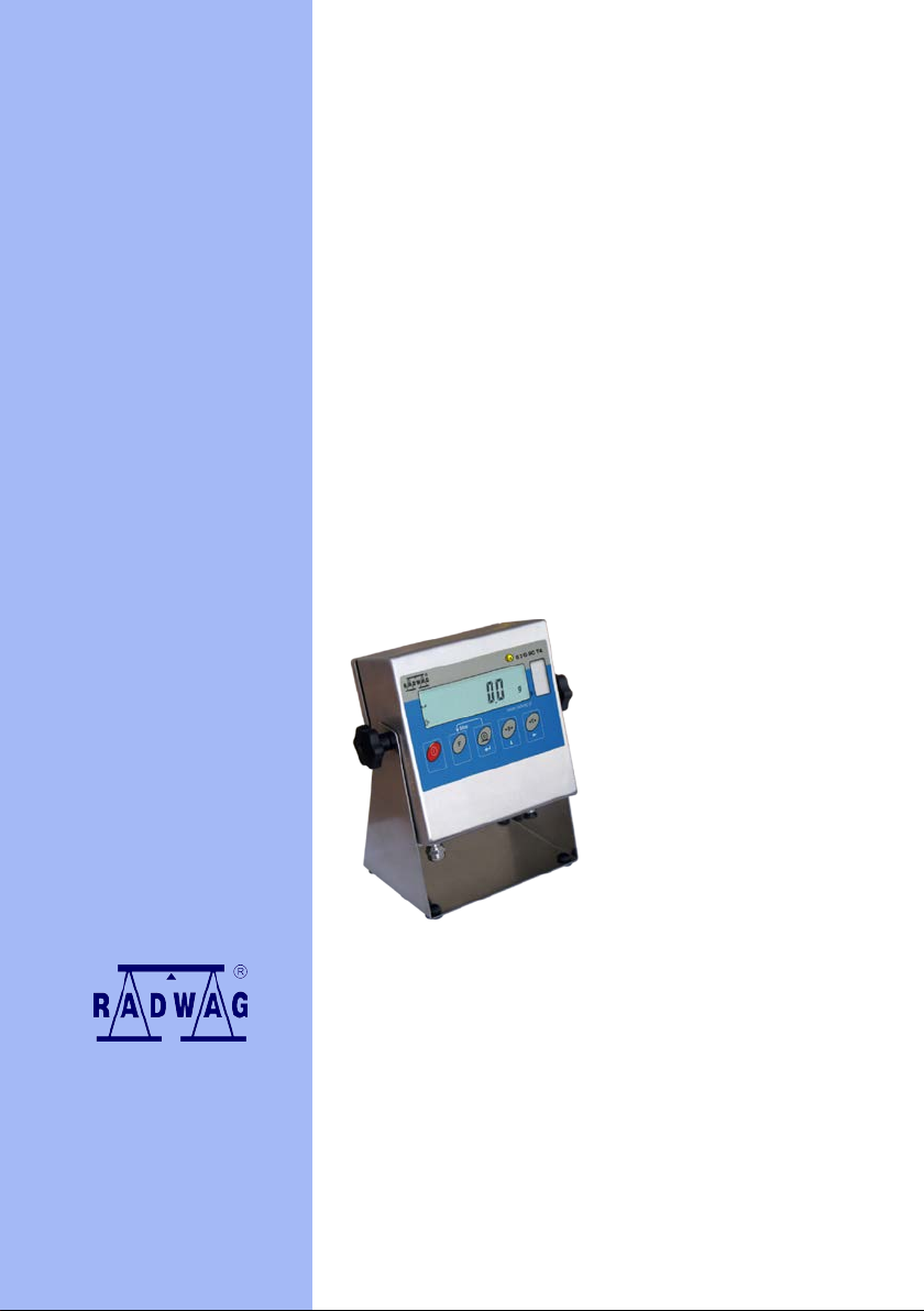
User manual
of PUE C/31 H/EX indicator
applicable in:
WPT……../EX,
WTC……./EX.
Manual number:
EXI-01-04-06-14-GB
BALANCES AND SCALES
RADWAG 26 – 600 Radom, Bracka 28, POLAND
Phone +48 48 38 48 800, phone/fax: +48 48 385 00 10
Sales department +48 48 366 80 06
www.radwag.com
Page 2

- 2 -
JUNE 2014
EXI-01-04-06-14-GB
Page 3

- 3 -
TABLE OF CONTENTS
1. DESIGN AND INTENDED USE .......................................................................................... 4
2. SECURITY REQ UIREMENTS............................................................................................. 6
2.1. ATEX marking – symbols meaning .............................................................................. 7
2.2. Rating plates for indicator and scale ............................................................................ 8
2.3. Placement of information stickers ................................................................................ 9
3. START-UP ........................................................................................................................ 10
3.1. Scale placing ............................................................................................................. 10
3.2. Connecting power supplier ........................................................................................ 11
3.3. Switching on .............................................................................................................. 14
4. CLEANING ....................................................................................................................... 14
5. SERVICE AND REPAIRING ............................................................................................. 14
6. FUNCTIONS ..................................................................................................................... 15
7. KEYBOARD ..................................................................................................................... 16
8. FUNCTINS OF KEYS ....................................................................................................... 16
9. INSCRIPTIO NS AND PICTOGRAMS ............................................................................... 17
10. USER MENU ................................................................................................................... 17
11. BROWSING USER’S MENU ........................................................................................... 18
11.1.Keypad…. ................................................................................................................ 18
11.2.Return to weighing .................................................................................................... 19
12. WEIGHING...................................................................................................................... 19
12.1.Tarring….. ................................................................................................................ 19
12.2.Tarring by inscribing tare value ................................................................................. 20
12.3.Zeroing…. ................................................................................................................ 21
12.4.Weighing for two range scales .................................................................................. 21
12.5.Setting of basic unit for weighing .............................................................................. 22
12.6.Temporary weighing unit .......................................................................................... 23
13. MAIN PARAMETERS ..................................................................................................... 24
13.1.Adjustment of filtering level ....................................................................................... 24
13.2.Autozero.. ................................................................................................................. 25
13.3.Tare function operation ............................................................................................. 26
13.4.Median filter .............................................................................................................. 27
13.5.Determining the minimal mass .................................................................................. 28
14. OPERATION MODES ..................................................................................................... 28
14.1.Enabling operating modes (functions) ....................................................................... 28
14.2.Determining number of accessible modes ................................................................ 29
14.3.Counting parts of identical weight ............................................................................. 30
14.4.+/- control referring to the inscribed standard mass .................................................. 33
14.5.Per cent deviation with reference to standard mass .................................................. 35
14.5.1.Mass standard weight determined by the measuring process ................................ 35
14.5.2.Standard mass inscribed to scale memory ............................................................. 36
14.6.Automatic tare .......................................................................................................... 37
14.7.Measurement of the max force – peak hold .............................................................. 38
14.8.Totalizing. ................................................................................................................. 38
14.8.1.Operation mode activation procedure .................................................................... 38
14.8.2.Totalizing procedure .............................................................................................. 39
14.8.3.Storing the last sum of weighings .......................................................................... 40
15. ADJUSTMENT ................................................................................................................ 41
15.1.Adjustment procedure .............................................................................................. 41
15.2.Start mass estimation ............................................................................................... 43
16. ERRORS ......................................................................................................................... 45
17. RESPECTIVE STANDARDS .......................................................................................... 45
EXI-01-04-06-14-GB
Page 4
- 4 -
1. DESIGN AND INTENDED USE
Indicator of PUE C/31H/EX type, in cooperation w ith a weighi ng platf orm , is
intended for fast and precise meas urements performed i n explosive areas .
Tarring throughout the who le measuring range allo ws to determine the net
mass of measured loads.
The PUE C/31H/EX series indicator consists of:
• Main PCB (scale)
• Stainless steel housing
• Power supply connector
• Input cable gland (from weighing platform)
• Functional grounding clamp
• Overlay
• Indicator holder
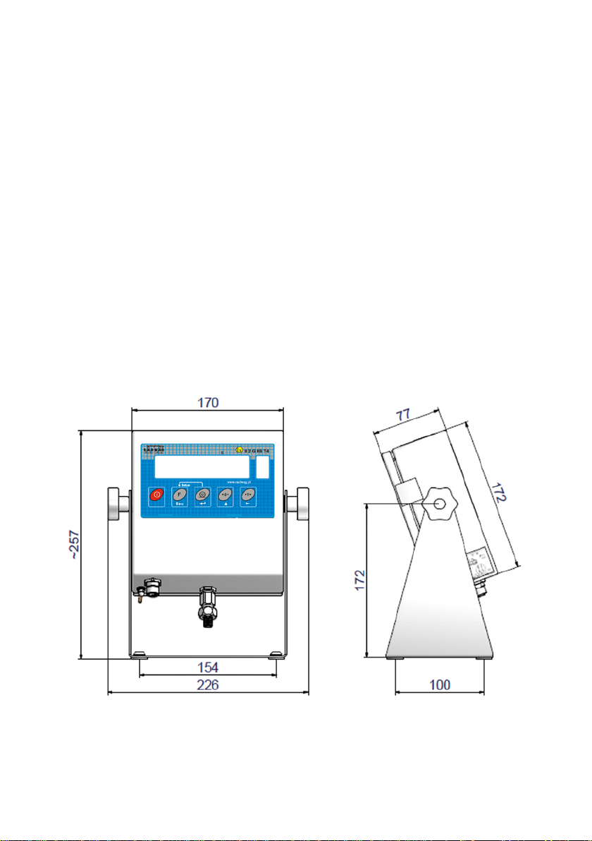
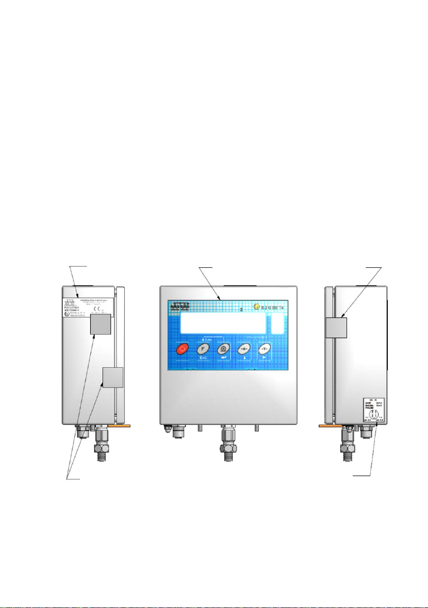
View - dimensions
Dimensions of PUE C/31H/EX indicator.
EXI-01-04-06-14-GB
Page 5
- 5 -
PUE C/31H/EX
o
o
125 Ω
1200 Ω
I/O marking +5V, E, AGND, REF+, REF-, +IN, -IN
Parameters identical for each clamp
KDB 06ATEX250
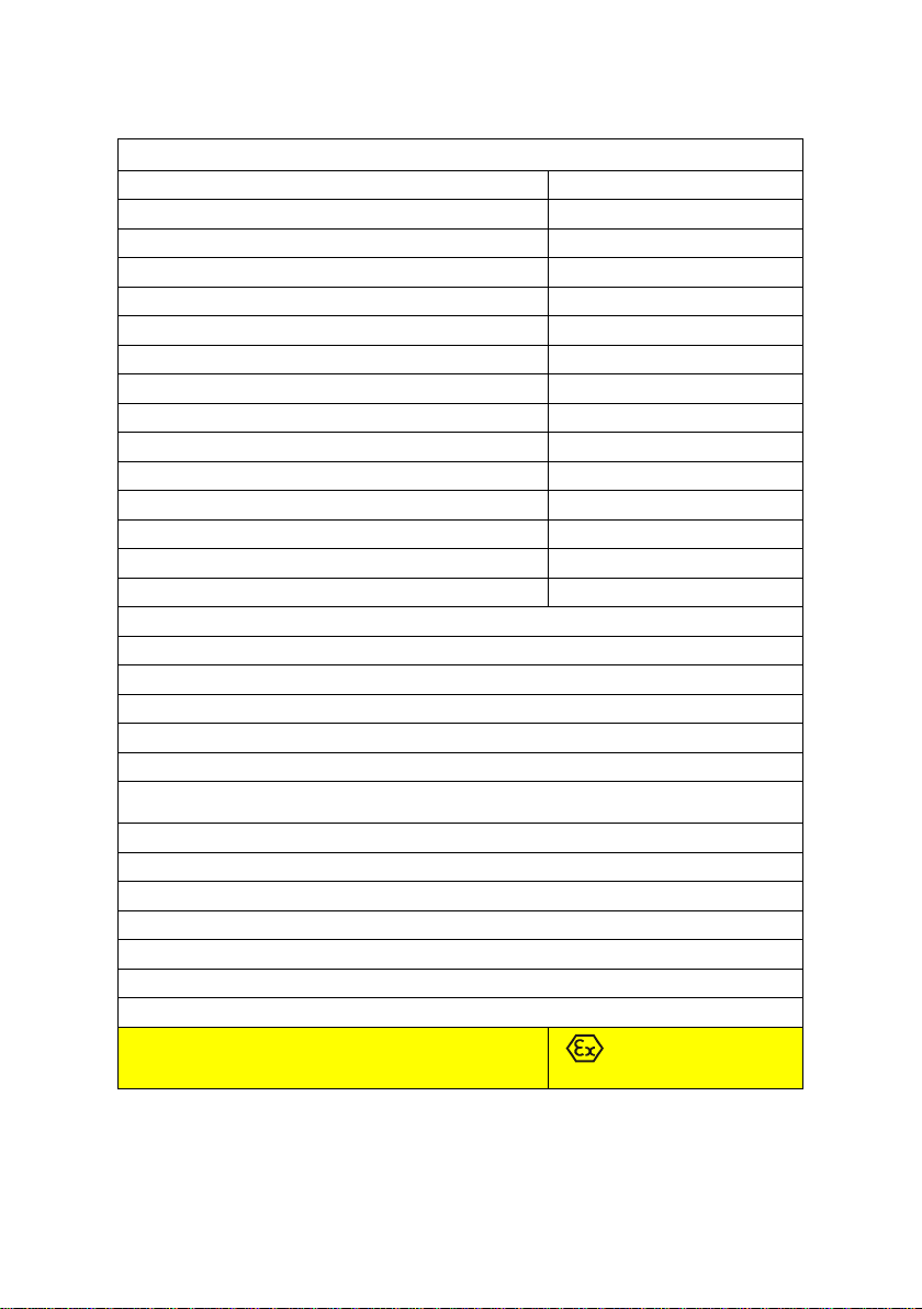
PUE C/31H/EX technical data:
Housing type stainless steel
Ingress Protection Rating IP66/67
Display type LCD
Keyboard Microswitch (500 000 cycles)
OIML class III
Maximum quantity of A/D converter divisions 8388608
Number of verification intervals 6 000
Maximum input voltage 19,5 mV
Maximum voltage per verification interval
Minimum voltage per verification interval
Ambient temperature -10
Minimum load cell impedance
Maximum load cell impedance
Connection of load cell 4 or 6 cables + shield
Number of ranges 1 or 2 ranges
Power supply - DC IN connector pin 1(4) pin 2(3)
Ui=9V
Ii=0,24A
Pi=0,6W
Ci≈0
Li≈0
3,25 µV
1 µV
C ≤ ta ≤ 40
C
DESIGNATION
EXI-01-04-06-14-GB
Uo=7,14V
Po=0,52W
Io=0,24A
Li≈0
Ci=6uF
Lo=40uH
Co=10nF
II 2G Ex ib IIC T 4
Page 6
- 6 -
2. SECURITY REQUIREMENTS
Please read this manual carefully prior the first usage. Following the
instruction, use the device as intended;
PUE C/31H/EX indicator, and scales with design based on the indicator,
can be used in explosive z one 1 and 2 where ther e is a mixtures of gases,
vapours and mists of II (second) explosion group and T1, T2, T3 or T4
temperature class.
WPT………/EX and W T C………/EX s cales, b ecaus e of the constr uction of
non-electric part of the platf orm and used materials, can be operated in 1
and 2 zone where t here are mixtures of gases , vapours and mists of IIA,
IIB, or IIC group – according to „Technical Documentation” of the scale.
Anti-explosive safety of the PUE C/31H/EX indicator, and of scales
with design based on the indicator is assured by:
• Power supplied from the ZRi02 power supplier II (2) G [Ex
ib] IIC KDB 06ATEX251 manufactured b y RADWAG, placed
behind the hazardous area or from another adapter with
appropriate parameters of intrinsically safe electrical circuit.
• Intrinsically safe design of PUE C/31H/EX indicator complying
with:
EN 60079-0 and EN 60079-11 standards, confirmed by
KDB 06ATEX250 certificate
• Using load cells certified for conformity with ATEX directive (on
anti-explosion safety)
• Making non-electric parts pf the scale in compliance with EN
13463-1 standard
• Observing recommendations in this manual by users
- marking of paragraphs crucial for anti-explosion safety
EXI-01-04-06-14-GB
Page 7

- 7 -
Electrical equipment -
Explosive atmosphere:
Symbol of the
Gas explosiveness group -
Temperature class –
Equipment group:
Categories for group II
zone 2
Security level
2.1. ATEX m ar ki ng – symbols meaning
I – underground parts
of mines
II – all other places liable
to be endangered by
explosive atmospheres
equipment:
1 - the device assures a
very high protection
level,
- to be operated in
zones 0,1,2
2 - the device assures a
high protection level,
- to be operated in
zones 1,2
3 - the device assures a
standard protection
level,
- to be operated in
G – caused by gas,
vapor and mist.
D – caused by dust.
compatible with one or
few kinds of antiexplosion designs
used anti-explosion
design type
o – oil protection
p – gas protection with an
excess pressure
q – sand protection
d – flame-proof protection
e – strengthened design
intrinsically safe design
ia -
for operation in zone
0,1,2,
ib -
intrinsically safe design
for operation in zone 1,2,
examples:
-IIA: propane (T1)
-IIB: ethylene (T2)
-IIC: acetylene (T2)
:
benzene (T3)
butane (T2)
ethanol (T2)
hydrogen (T1)
surface max temperature
of the equipment parts that
are in touch with explosive
:
mixture
T1: 450
T2: 300
T3: 200
T4: 135
T5: 100
T6: 85
Temperature class
of the gas or vapor
auto ignition
T1: > 450
T2: > 300
T3: > 200
T4: > 135
T5: > 100
T6: > 85
Gas atmosphere:
- Ga
- Gb
- Gc
Dust atmosphere:
- Da
- Db
- Dc
0
C
0
C
0
C
0
C
0
C
0
C
:
0
C
0
C
0
C
0
C
0
C
0
C
EXI-01-04-06-14-GB
Page 8
- 8 -
PUE C/31H/EX indicator is a device of group II with „ ib ” pr otec tio n theref or e
“Gb” protection symbol may be omitted.
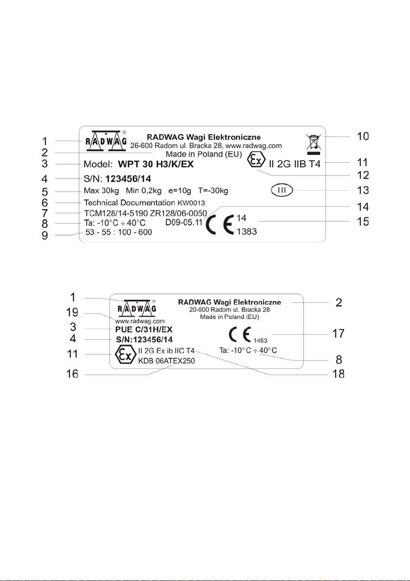
2.2. Rating plates for indicator and scales
Rating plate of the scale (exemplary)
Rating plate of the PUE C/31H/EX indicator
1 – Manufacturer’s Logo
2 – Name and phone number of the manufacturer
3 – Scale type, indicator type
4 – Factory number
5 – Metrological parameters of the scale
6 – Technical Documentation number
7 – Type approval certificate number (for verified scales)
8 – Ambient temperature
9 – geographical zone, ie. latitude and long itu de data and the hei ght abo v e
the level – only verified scales
EXI-01-04-06-14-GB
Page 9
- 9 -
Protective stickers
Rating plate of the PUE
C/31H/EX indicator
Protective sticker
Power supply marking
Overlay with
ATEX marking
10 – WEEE symbol
11 – ATEX marking relating to the scale (see point 2.1)
12 – EX marking stating that the device is intended for operation in
explosive areas
13 – accuracy class marking
14 – certificate number of used load cell
15 – CE marking with two last digits of the year of production and with a
number of notified body for NAWI directives
16 – ATEX certificate number relating to an indicat or
17 – CE marking with the number of a notified body supervising EX device
production
18 – ATEX marking relating to the indicator (see point 2.1)
19 – manufacturer website address
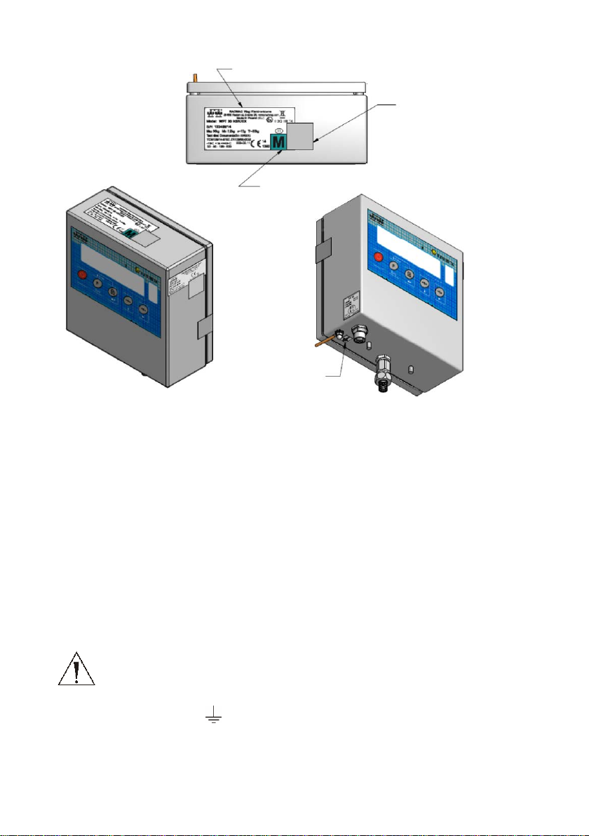
2.3. Placement of information stickers
EXI-01-04-06-14-GB
Page 10
- 10 -
Functional
grounding mark
Protective sticker
Verification sticker
Rating plate of the scale
3. START-UP
Please read this manual carefully prior the start-up. Following the
instruction, use the device as intended.
3.1. Scale placing
• The scale should be unpacked outside the hazardous area.
• Before moving the scale to the place of operation prepare a cable
for earthing the device against electrostatic charges.
NOTICE!!
In order to protect the indicator against gathering electrostatic
charge it is necessary to earth/zero its housing.
Connect the earthing lead/wire to cable connection points
marked with „
• Situate scales and an indicat or in hazardous area and connect
earthing/zeroing.
EXI-01-04-06-14-GB
” . See the manual for details about ea rthing.
Page 11
- 11 -
NOTICE!
Intrinsicaly safe circuit parameters for power supplier used
for PUE C31H/EX indicator
Uo
8,61
V
Io
0,24
A
Po
0,52
W
Um
255
V
Lo
200
uH
Co
5,7
uF
Li
≈0
uH
Ci
≈0
uF
Mounting the indicator, placing the weighing platform and
earthing/zeroing should be performed when the explosive
atmosphere cannot appear.
Indicators with cable can be mounted on the rack, on the wall or on
the table using a special mounting kit.
Weighing platform should be placed on even and stable ground far
from sources of hit and draughts. It should be also levelled out
using the feet.
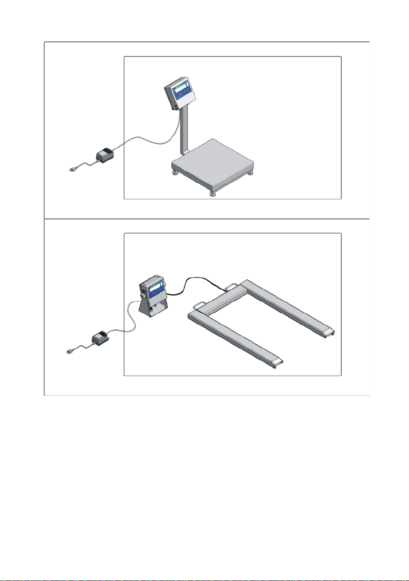
3.2. Connecting power supplier
1. Place the power supplier outside the hazardous area.
2. Connect the plug that terminates the supply cable (up to 20m) to
the socket marked as DC IN.
3. Connect the supplier to mains (230V AC).
4. In case of not using the scale unplug it from the mains.
NOTICE!
Scales with PUE C/31H/EX indicators can be supplie d o n ly
from ZRi02 power suppliers
II (2) G [Ex ib] IIC KDB
06ATEX251 of RADWAG production, placed outside the
hazardous area, or from another supplier characterized by
below presented parameters of intrinsically safe electrical
circuit.
EXI-01-04-06-14-GB
Page 12
- 12 -
Safe area
Hazardous area EX
AC 230v 50Hz
Safe area
Hazardous area EX
AC 230v 50Hz
ZRi02 power
ZRi02 power
Scale with the indicator on a cable
Scale with the indicator on a pillar
supplier
cable up to 20m
supplier
cable up to 20m
Supplier connection
EXI-01-04-06-14-GB
Page 13
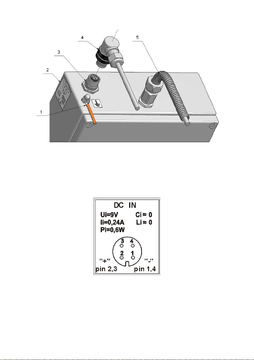
- 13 -
1 – earthing terminal
2 – power supply socket description
3 – power supply socket
4 – power supply socket
5 – screened load cell cable
Power connector parameters
EXI-01-04-06-14-GB
Page 14
- 14 -
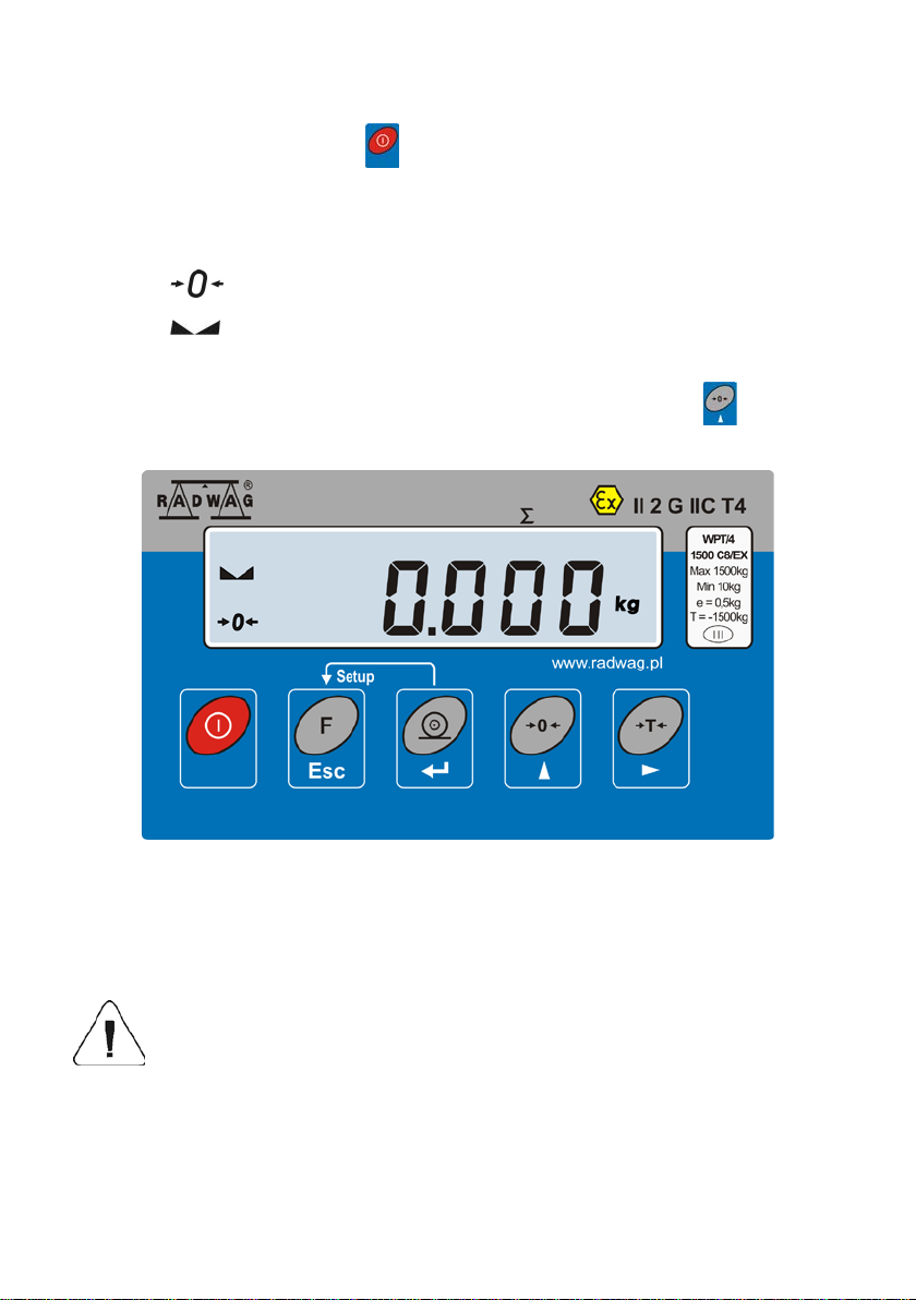
3.3. Switching on
• Press the ON/OFF key – keep pressing for about 1 sec.
• After switching on, wait for the test completion.
• The indication shall equal zero and the following pictograms shall be
seen:
- zero indication
- equilibrium
kg - weighing mode
• If the indication does not equal zero press the zeroi ng key
.
Ready to use.
4. CLEANING
Cleaning can be performed only after unplugging from mains (230V AC). Use agents and
materials that do not cause gathering electrostatic charges on elements of the scale!
Do not use abrasive agents and solvents because
it can cause damage of the casing.
Cleaning should be performed when the appearance of explosive
gases is impossible
5. SERVICE AND REPAIRING
EXI-01-04-06-14-GB
Page 15

- 15 -
In case of any problems with appropriate operation of the indicator, contact
the manufacturer’s service centre or any service centre authorised by
RADWAG.
In case of any fault or dysfunction the device should be passed to the
manufacturer’s s ervice centre or, if this is not possible, the fault should be
reported in order to settle the conditions of repair.
Any intrusion (alteration, repair etc.) in the indicator or scale
based on PUE C/31H/EX indicator, by unauthorised persons
will cause a forfeiture of validity of certificates, declarations
and manufacturer’s warranty.
6. FUNCTIONS
• Filtering
• Autozero
• Minimal mass
• Counting pieces
• +/- control
• Deviation in per cents
• Peak hold
• Automatic tare
• Tare memory
• Manual tare inscription
• User’s calibration
• Totalizing
It is possible to disable selected functions thus making the scales adjusted
to one’s own needs. Access may be permitted to some particular functions
only if required. The user menu allows enabling/disabling a given
parameter, see the further part of the manual.
EXI-01-04-06-14-GB
Page 16

- 16 -
Information window
Display window
Function keys – „keypad”
7. KEYBOARD
8. FUNCTINS OF KEYS
NOTICE:
Pressing
wherein the change is valid until setting parameters procedure is
completed. See the further part of the manual for details.
EXI-01-04-06-14-GB
Power on/off – keep it pressed for about 1 sec
Function key (selection of operation mode)
Confirmation of changes
- zeroing
- tarring
and k eys results in change of particular keys functions,
Page 17

- 17 -
FIL
PCS
HiLo
PCS
kg (g)
Net
P1 rEAd
P 1.1 Fil
| 2 P 1.2 Auto
|
YES
P 1.3 tArA
|
no
P 1.4 Fnnd
|
no
P2 Prnt
P2.2 S_Lo
|
9. INSCRIPTIONS AND PICTOGRAMS
O.n. Inscription Description
1.
2.
3.
4. Auto
5. toP
6. Add
7.
8.
9.
10.
11.
12. Min
13. OK.
14. Max
Filtering level
Parts counting
+/- control in relation to reference mass
Control and correction of zero indication of scal e
Measurement of max. force influencing weighing pan
Totalizing
Scale in autozero range (indication = precise zero)
Result of measurement is stable (ready for readout)
Scale in operating mode counting pieces
Scale in operating mode weighing
Scale is tarred.
+/- control in relation to reference mass – setting lower
threshold or mass below first range
+/- control in relation to reference mass: mass of load
between set threshold
+/- control in relation to reference mass – setting upper
threshold or mass above upper threshold.
10. USER MENU
The menu is divided into 5 basic groups. Each group has its individual
name starting with the capital letter P.
EXI-01-04-06-14-GB
Page 18

- 18 -
P3 Unit
P3.1 StUn
|
kg
P4 Func
P4.1 FFun
|
ALL
P4.2 Funi
|
no
P4.3 PcS
|
no
P4.4 HiLo
|
no
P4.5 PrcA
|
no
P4.6 Prcb
|
no
P4.7 AtAr
|
no
P4.8 toP
|
no
P4.9 Add
|
no
P6 CAL
P6.1 St_u
|
* FUNCTION *
P6.2 uCAL
|
* FUNCTION *
11. BROWSING USER’S MENU
User moves in the menu using the scale keyboard.
11.1. Keypad
EXI-01-04-06-14-GB
+
entering the main menu
inscribing tare value
+
selecting parameter of a given menu level
or changing the active parameter value
entering selected submenu or activation of
a parameter for modification
change confirmation
leaving a function without changes or
moving one level higher in the m enu
Page 19

- 19 -
11.2. Re tu rn to weighing
NOTICE:
Changes introduced into the scale memory will be permanently
saved after return to weighing.
Press F key
several times, keep pressing until message
<SAvE?> is seen.
Return to weighing
Upon noticing the message press: key – for changes confirmation or
key – for resigning. After completion of this procedure the scale returns
to weighing.
12. WEIGHING
Place a load on a weighing pan. After noticing stability
pictogram,
12.1. Tarring
In order to determ ine a net mass , deposit a package of load on a pan and
, read the weighing result.
wait for the indication to b e stable, next press TARE key -
(indication
goes back to zero, Net symbol is displayed on the left side of the display).
After depositing a load on a pan, the display indicates net mass. Tarring
can be done repeatedly in full weighing range of the scale. When using tare
EXI-01-04-06-14-GB
Page 20

- 20 -
Select the digit value
Select the digit to be set
function pay attention to maximum weighing range, it cannot be exceeded.
After removing the load and the package, display shows indication of sum
of tarred weights with minus sign.
NOTICE:
Tarring may not be performed when minus value or zero is displayed. In
such a case the display shows <Err3> message, short sound signal is
heard.
12.2. Tarring by inscribing tare value
It is possible to inscribe a tare value.
Procedure:
• Press simultaneously
and keys
• On the display you will see:
– select the digit to be set
– select the digit value
• Using
• Press
• The scale returns to the weighing mode and the value of tare is
displayed with the “–“ sign,
• Tare value can be inscribed any time in weighing mode.
and keys set tare value,
,
EXI-01-04-06-14-GB
Page 21

- 21 -
NOTICE:
Tarring by inscribing tare value cannot be performed when the tare value
has already been implemented into the scale memory. In such a case the
display shows <Err3> message, short sound signal is heard.
12.3. Zeroing
In order to zero the indic ation press zeroing k ey - . Zero value is shown
on a display next to symbols:
and .
The new zero point is treated b y the scale as the precise zero. Zeroing is
possible while stable status is shown on the display.
NOTICE:
Display status zeroing is possible only in range up to ±2% of maximum
scale capacity. If zeroed value is bigger than ±2% of maximum capacity,
display shows Err 2 message, short sound signal is heard.
12.4. Weighing for two range scales
Switching from the I range to the II range is carried out automatically after
exceeding the switching point value (Max of the I range).
Weighing in the II ra nge is s igna lled by a pictogram, located in the upper
left-hand corner of a display.
After unloading, the scale returns to zero. Weighing in the II range takes
place until unloading the pan.
II range weighing automatically turns to I range weighing after taking the
load off the weighing pan when the scale returns to AUTOZERO zone – the
pictogram is seen.
EXI-01-04-06-14-GB
Page 22

- 22 -
12.5. Setting a basic weighing unit
The user may set a weighing unit to be active after turning on the scales.
Procedure:
• Following point 11 of this manual enter <P3.Unit> submenu, next:
• Press key several times to view available units:
Selection:
A. When the basic unit is set to [kg], users can toggle between: [kg, lb,
N]. For verified scales [lb] is not accessible.
B. When the basic unit is set to [g], users can toggle between: [g, ct].
For verified scales [lb] is not accessible.
• Upon unit selection press
following win do w :
key, wait for the scales to return to the
EXI-01-04-06-14-GB
Page 23

- 23 -
Save changes and return to weighing:
See point - 11.2. – return to weighing.
NOTICE:
Upon activation the scale operates with a set basic unit.
12.6. Temporary weighing unit
This function allows users to choose unit for indication.
The unit is valid until the scale is switched off or until another unit is
chosen.
In order to perform the following procedure, operation mode <P4.2.Funi>
must be accessible, see point 14.1.1 – Enabling operating modes.
Procedure:
• Press F key
, next:
• Confirm selection of a given unit and wait for the scale to return to
weighing.
Selection:
A. When the basic unit is set to [kg], users can toggle between: [kg, lb
– not accessible for verified scales, N].
B. When the basic unit is set to [g], users can toggle between: [g, ct,
lb – not accessible for verified scales].
EXI-01-04-06-14-GB
Page 24

- 24 -
13. M AIN PARAMETERS
User can adjust the scale to external ambient conditions (setting filters) or
individual requirements (autozero, tare value). Respective parameters can
be found in <P1.rEAd> parameters group.
13.1. Adjustment of filtering level Procedure:
• Following point 11 of this manual enter <P1.rEAd> submenu, next:
1 - 4 - filtering levels to be selected (depending on the ambient
conditions)
Return to weighing:
See point - 11.2. – return to weighing.
NOTICE:
The higher filtering level the longer stabilisation time.
EXI-01-04-06-14-GB
Page 25

- 25 -
13.2. Autozero
„AUTOZERO” function has been introduced in order to ensure precise
indication. The intended use of this function is automatic control and
correction of zero indication.
When function is active comparison of results takes place at specified time
intervals. If results differ by value smaller than declared AUTOZERO range,
e.g. one division, scale is zeroed aut omatically, stable state is marked –
and zero indication – is displayed.
When AUTOZERO function is enabled, each result starts from precise
zero. However there are some cases when this function can disturb
measurement, e.g. very slow process of load depositing on the pan (load
pouring). In such case, correction system for zero indication can also
correct indication of real mass of load.
Procedure:
• Following point 11 of this manual enter <P1.rEAd> submenu, next:
AUTO no - autozero disabled
AUTO YES - autozero enabled
Return to weighing:
See point - 11.2. – return to weighing.
EXI-01-04-06-14-GB
Page 26

- 26 -
tArA
AtAr
-
automatic tare function on - stored in scale memory
tArA
no
-
automatic tare function off (scale tarring by means of
tArA
tArF
-
tare memory function – stores last value of tare in
13.3. Tare fu n ction operation
This function enables the user to set appropriate parameters (depending on
needs) for tare function.
Procedure:
• Following point 11 of this manual enter <P1.rEAd> submenu, next:
after unplugging it from mains (see point 15.5 for
description);
T key )
scale memory. It is automatically displayed after
starting the scale.
Return to weighing:
EXI-01-04-06-14-GB
See point - 11.2. – return to weighing.
Page 27

- 27 -
13.4. Median filter
The role of the median filter is to eliminate short lasting interference (e.g.
mechanical shocks).
Procedure:
• Following point 11 of this manual enter <P1.rEAd> submenu, next:
Fnnd no - median filter disabled
Fnnd YES - median filter enabled
Return to weighing:
See point - 11.2. – return to weighing.
EXI-01-04-06-14-GB
Page 28

- 28 -
Select the digit to be set
Select the digit value
13.5. De termining the minimal load S_Lo parameter works for automatic tare.
The rule is that no automatic tare is performed until the indication drops
below S_Lo value (gross).
Procedure:
• Following point 11 of this manual enter <P2.Prnt> submenu, next:
Return to weighing:
See point - 11.2. – return to weighing.
14. OPERATION MODES
14.1. En abling operating modes (functions)
In this group of parameters users declare functions they want to use after
pressing F key -
Procedure:
• Following point 11 of this manual enter <P4.Func> submenu, next:
EXI-01-04-06-14-GB
while in weighing mode.
Page 29

- 29 -
no - mode disabled
YES - mode enabled
NOTICE:
Enabling procedure for other operation modes is analogous to the one
described above.
Return to weighing:
See point - 11.2. – return to weighing.
14.2. Determining number of accessible modes
The user may decide whether upon pressing F key
modes are to be accessible (option <ALL>), or only one, selected out of
the list.
Procedure:
• Following point 11 of this manual enter <P4.Func> submenu, next:
all the operation
EXI-01-04-06-14-GB
Page 30

- 30 -
Return to weighing:
See point - 11.2. – return to weighing.
14.3. Counting parts of identical weight
The standard solution is equipped with option of counting small pieces of
the same mass. If parts counting is to be performed in a container, its
weight must be recorded into the scale memory (the container must be
tarred).
NOTICE:
1. Counting pieces mode does not operate with other functions,
2. Parts counting function is not active after scale’s restart.
Procedure:
• Enter <PcS> submenu (first make the operation mode accessible -
see point 14.1):
EXI-01-04-06-14-GB
Page 31

- 31 -
• The blinking value on the display informs of quantity of a sample. By
means of
key, set quantity of a sample and press key to
confirm:
• If option <LASt> has been chosen than the most recent weight value
of a single piece is displayed for 3 sec., the program proceeds to
Parts Counting mode automatically setting the previously displayed
value.
• If option <FrEE> has been chosen, the program displays the following
window:
EXI-01-04-06-14-GB
Page 32

- 32 -
Pilsujący symbol
Blinking symbol
• Using and keys, enter the demanded quantity of sample,
where:
- selection of the digit to be set, - selection of the digit
value,
• Press
key for confirmation,
• <LoAd> message is displayed, the following window is seen:
• If pieces are to be weighed in a container, it is necessary to tare it,
next declared number of pieces must be put onto the weighing pan,
their mass confirmed after stabilization of the indication (symbol
on a display):
• The program automatically calculates weight of a single element and
proceeds to the Parts Counting mode displaying number of weighed
elements (pcs):
NOTICE:
1. If the user presses the
pan, the message -Lo- is indicated for a few seconds and the scale
automatically returns to weighing.
2. In order to obtain reliable results, it is recommended to load the
weighing pan with elements, mass of which is greater than 5 reading
units.
EXI-01-04-06-14-GB
key when there are no elements on the
Page 33

- 33 -
Select the digit to be set
Select the digit value
3. If a single element weight is not greater than a reading unit, then
message <Err5> is shown on the scale display (see point 19. Error
Messages), short sound signal is heard, next the scale returns to
weighing.
Function deactivation:
Press F key
twice.
14.4. +/- control referring to the inscribed standard mass The program allows entering checkweighing threshold values (Min, Max.
Procedure:
• Enter <HiLo> function (first make the operation mode accessible -
see point 14.1):
• The program proceeds to window for setting the lower threshold (Min):
EXI-01-04-06-14-GB
Page 34

- 34 -
load mass below the I threshold
load mass between the
load mass above the II threshold
Select the digit to be set
Select the digit value
• Press key to confirm, the program proceeds to window for setting
the upper threshold (Max):
• Press
key to confirm, the program automatically returns to
weighing with threshold values recorded into the memory.
• During setting the threshold values the following cases take place:
thresholds
NOTICE:
If a user erroneously enters a value of the lower threshold higher than the
upper one, the scale indicates an error message and returns to weighing.
Function deactivation:
Press F key
twice.
EXI-01-04-06-14-GB
Page 35

- 35 -
Blinking symbol
14.5. Per cent deviation with reference to standard mass
This program allows to meas ure deviation in per cent with reference to a
standard mass. The standard mass can be estimated by weighing (PrcA
function) or inscribed by a user (PrcB function).
14.5.1. Mass standard weight determined by the measuring process Procedure:
• Enter <PrcA> function (first make the operation mode accessible -
see point 14.1):
• Message <LoAd> is displayed, the following window is seen:
• On a weighing pan place the load, mass of which is to be taken as a
• The scale display shows indication 100,000%,
• From this moment display will indicate weight deviation of load placed
EXI-01-04-06-14-GB
standard, upon stabilization of the indication (symbol
press
key for confirmation,
displayed)
on a pan, wherein the said deviation is referred to the mass of
standard (in %):
Page 36

- 36 -
Blinking symbol
Function deactivation:
Press F key
14.5.2. Standard mass inscribed to scale memory Procedure:
• Enter <Prcb> function (first make the operation mode accessible -
see point 14.1):
• The program proceeds to the following window:
twice.
• Using and keys, set the mass standard weight,
• Press
• The scale display will show indication 0,000%,
• From this moment display will indicate weight deviation of load placed
EXI-01-04-06-14-GB
where:
- selection of the digit to be set, - selection of the digit
value
key for confirmation,
on a pan, wherein the said deviation is referred to the mass of
standard (in %).
Page 37

- 37 -
Function deactivation:
Press F key
twice.
14.6. Automatic tare
This function is useful for fast net mass determination of weighed load
when the tare value for each next load to be weighed is different. In case
when the function is active the cycle of scales operation looks as follows:
• press zeroing key when the pan is empty,
• place the container for pieces,
• when indication is stable, automatic tarring of the container mass
gets started (Net marker appears in the upper part of the display),
• place a sample in the container,
• display indicates net mass of a sample,
• remove the sample together with the container,
• scale displays zero indication (zeroing),
• place a container for the next sample. When indication is stable
automatic tarring gets started (Net marker appears in the upper part of
the display),
• place next sample in the container.
Activation procedure:
Function deactivation:
Press F key
EXI-01-04-06-14-GB
twice.
Page 38

- 38 -
14.7. Measurement of the max force – peak hold Procedure:
• Enter <toP> function (first make the operation mode accessible - see
point 14.1):
• Max pictogram visible in upper part of the display is a confirmation of
toP function activation:
• Apply a force to the weighing pan. The display of scale
will latch the maximum value of the force.
• Remove loads from the pan.
• Before next measurement press
.
Function deactivation:
Press F key
twice.
14.8. Totalizing
The program enables totalizing the mass of weighed loads and the
totalized mass printout (for EX scales the printout is disabled).
14.8.1. Operation mode activation procedure
EXI-01-04-06-14-GB
Page 39

- 39 -
• Enter <Add> function (first make the operation mode accessible - see
point 14.1)
• „P” letter visible on the left of the display is a confirmation of <Add>
function activation:
14.8.2. Totalizing procedure
• Following point 14.8.1 enter <Add> function,
• Place the first load on a weighing pan. If the load is to be weighed in a
container, it is necessary to tare it before putting the first load into it,
its mass must be confirmed by pressing
the indication (symbol
on a display),
• Sum of weighings is displayed („▲” pictogram in the upper right-hand
corner of the display).
key after stabilization of
• Take off the load , the scale indication returns to ZERO, letter „P”
appears on the left,
• Place next load on the pan,
EXI-01-04-06-14-GB
Page 40

- 40 -
• Upon indication stabilization press key, sum of the first and
second weighing is displayed („▲” pictogram in the upper right-hand
corner of the display):
• In order to finish the procedure of totalizing, press
(either with a
load on the pan or after taking it off):
• If the
key is pressed again while load is being placed on a
weighing pan, the sum of previously performed measurements is
deleted, <unLoAd> message is displayed - unload the pan to return to
ZERO . Letter „P” will appear. The scale is ready for the next totalizing
procedure.
• If the
key is pressed again while load is not being placed on a
weighing pan, the sum of previously performed measurements is
deleted, the scale is ready for the next totalizing procedure.
14.8.3. Storing the last sum of weighings
After interrupting the procedure of totalizing (e.g. turning off the scale) it is
possible to restart with the last sum of weighings. In order to do it:
• enter <Add> function (see point 14.8.1),
• last sum of weighings is seen on the display, the displayed value
comes from the scale memory,
• press
key in order to continue totalizing, the indication returns to
ZERO and the letter „P” appears on the display; next load may be
placed on the scale.
• press
, or key in order to finish totalizing, the letter „P”
appears on the display; the scale is ready for the next totalizing
procedure.
EXI-01-04-06-14-GB
Page 41

- 41 -
NOTICE:
In case of a display range overflow in totalizing, the program displays error
<5-FULL>. The user must either take the load off the pan and press
key in order to complete totalizing or replace the load with ano ther one (of
lower mass) not resulting in display range overflow.
Function deactivation:
Press F key
twice.
15. ADJUSTMENT
Only for verified scales
In order to ensure perfect weighing accuracy it is required to introduce into
the scale memory a factor correcting the indications – it is so called
adjustment. Adjustment should be performed when the user starts weighing
or when dynamic change of temperature occurs. Before starting the
procedure, loads should be removed from the pan.
15.1. Adjustment procedure Procedure:
• Following point 11 of this manual enter <P6.CAL> submenu, next:
EXI-01-04-06-14-GB
Page 42

- 42 -
• The following messages are displayed:
• A new start mass is adjusted during this period of time. After that a
mass of calibration weight is shown (e.g. 3 000kg).
• Put the calibration weight on the weighing pan and press key,
adjustment process starts, the following message is seen:
• The <unLoAd> message informs about adjustment process
completion:
EXI-01-04-06-14-GB
Page 43

- 43 -
• Take off the load, message <donE> is displayed for 1 sec., the scale
shows the adjustment submenu name:
• Adjustment process may be interrupted at any time by pressing
key, the following message informs about abortion of a process:
NOTICE:
1. It must be remembered to perform calibration when the pan is
unloaded!
2. If the adjustment takes more than 15 sec. the program displays an
error message <Err8>, short sound signal is heard. Press
key and
perform the adjustment again simultaneously maintaining as stable
ambient conditions as possible!
Save changes and return to weighing:
See point - 11.2. – return to weighing.
15.2. Start mass estimation
If the scale does not require the f ull calibration pr ocess, or if the user lacks
demanded number of mass standards, it is possi ble to adjust only a new
start mass.
Procedure:
• Following point 11 of this manual enter <P6.CAL> submenu, next:
EXI-01-04-06-14-GB
Page 44

- 44 -
• the program displays the following set of messages:
• upon completion of the start mass estimation process the scale shows
the parameter name:
• start mass estimation process may be interrupted at any time by
key, the following message informs about abortion of a
pressing
process:
NOTICE:
If the start mass estimation takes more than 15 sec. the program displays
an error message <Err8>, short sound signal is heard. Press
key and
perform the adjustment again simultaneously maintaining as stable ambient
conditions as possible!
Save changes and return to weighing:
See point - 11.2. – return to weighing.
EXI-01-04-06-14-GB
Page 45

- 45 -
Err2
-
Value beyond the zero range
Err3
-
Value beyond the tare range
Err4
-
Calibration mass or start mass beyond the acceptable
Err5
-
Mass of a single piece lower than the scale division.
Err7
-
Power down time was to short (should be over 3s)
Err8
-
Operation time exceeded (tarring, zeroing, start mass
null
-
Zero value from the AD converter
FULL2
-
Measurement range overflow
LH
-
Start mass error, the mass on the weighing platform
start mass)
5–FULL
-
Display range overflow in totalizing
16. ERRORS
range (±1% for weight, ±10 for start mass).
estimation, adjustment)
is beyond the acceptable range (from -5% to +15% of
NOTICE:
1. The user is informed about occurrence of errors Err2, Err3, Err4,
Err5, Err8, null by means of a short sound signal (1 second).
2. Error FULL2 is signalled by a sound signal lasting until the over
excessive load is taken off the pan.
17. RESPECTIVE STANDARDS
PUE C/31H/EX indicator is manufactured in accordance with the following
standards:
- EN 61326-1:2006 Electrical equipment for measurement, control and
laboratory use - EMC requirements -- Part 1: General requirements,
- EN 61010-1:2011 Safety requirements for electrical equipment for
measurement, control, and laboratory use -- Part 1: General requirements,
- EN 60079-0:2013 + A11:2014-03 Explosive atmosph er es -- Part 0:
Equipment – General requirements,
- EN 60079-11:2012 Explosive atmospheres -- Part 11: Equipment
protection by intrinsic safety "i".
EXI-01-04-06-14-GB
Page 46

- 46 -
EXI-01-04-06-14-GB
Page 47

- 47 -
MANUFACTURER
OF ELECTRONIC EQUIPMENT
RADWAG WAGI ELEKTRONICZNE
POLAND, 26 – 600 Radom, Bracka 28
Phone: +48 48 38 48 800, phone/fax: + 48 48 385 00 10
Sales dpt.: + 48 48 366 80 06
www.radwag.com
EXI-01-04-06-14-GB
 Loading...