

Wireless Home Security System
Cat. No. 49-2551A
OWNER’S MANUAL
Please read before using this equipment.
with Emergency Phone Dialer
Plug,n Power
®
Compatible
B

2
INTRODUCTION
© 1999 Tandy Corporation.
All Rights Reserved.
RadioShack and Plug ’n Power are registered trademarks used by Tandy Corporation.
You can install your RadioShack Wireless Home Security System with Emergency Phone Dialer anyw here in your
house using the exis tin g hou se wir i ng.
The system operates using radio frequencies, thus eliminating the need for
additional wiring. It includes a handheld remote, one keychain remote, two
wireless sensor trans mitters, a motion
detector, and a lamp module so you
can immediately begin using your system. The console can monitor up to 16
security zones (with ad ditional r emote
sensors) and sound its built-in alarm
when a violation occurs in any zone.
Here are some of the features of your
system.
Two Wireless Sensor Transmitters
— trigger the console’s built-in alarm
when a secured door or window opens
(additional sensors, RadioShack Cat.
No. 49-2585).
Handheld Remote
— lets you arm
and disarm the system and control the
lights connected to Plug ’n Power modules (additional handheld remotes,
Cat. No. 49-2551T).
Keychain Remote
— lets you conveniently arm and disarm the system as
you come and go and turn on/off lights
and appliances (additional keychain
remotes, Cat. No. 49-2591).
Lamp Module
— lets you turn on/off a
lamp using a remote control. The lamp
also flashes on and off during an alarm
(additional lamp modules, Cat. No. 61-
2682).
Motion Detector
— protects an area
where an intruder might enter (additional motion detectors, Cat. No. 49-
2589).
Plug ’n Power Compatible Design
—
lets you add a total of 16 wireless sensor transmitters, lamp modules, motion detectors, and other accessories
to customize your home security system.
Supervised Operation
— keeps track
of each wireless sensor transmitter’s
status and alerts you if there is a problem (such as an intrusion or a lo w battery).
Built-In Telephone Voice Dialer
—
dials a friend or neighbor and plays
back your recor ded message when a
violation occurs.
Please read this entire manual carefully so you understa nd how to correctly
install and use this security system.
3
Notes:
• In addition to the par ts provided,
you need one 9V alkaline batter y
to operate the console; six AAA
alkaline batteries — two to operate the keychain remote control
and four to operate the handhe ld
remote control; and eight AA al ka line batteries — two in eac h wireless sensor transmitter and four to
operate the motion detector. Alkaline batteries in these sizes, are
available from your local RadioShack store.
• The suitability of this system to
perform as a burglar alarm system
or as an emergency service
device has not been evaluated by
Underwriters’ Laboratories, Inc.
• The wireless sensor transmitters
are supplied with NC (Normally
Closed) magnetic switches.
• You cannot use NO (Normally
Open) magnetic switches wi th thi s
sensor.
Warning
: To prevent fire or shock hazard, do not expose this product to rai n
or moisture.
WARNING
:
To reduce the risk of fire or
shock hazard, do not expose this product to rain
or moisture.
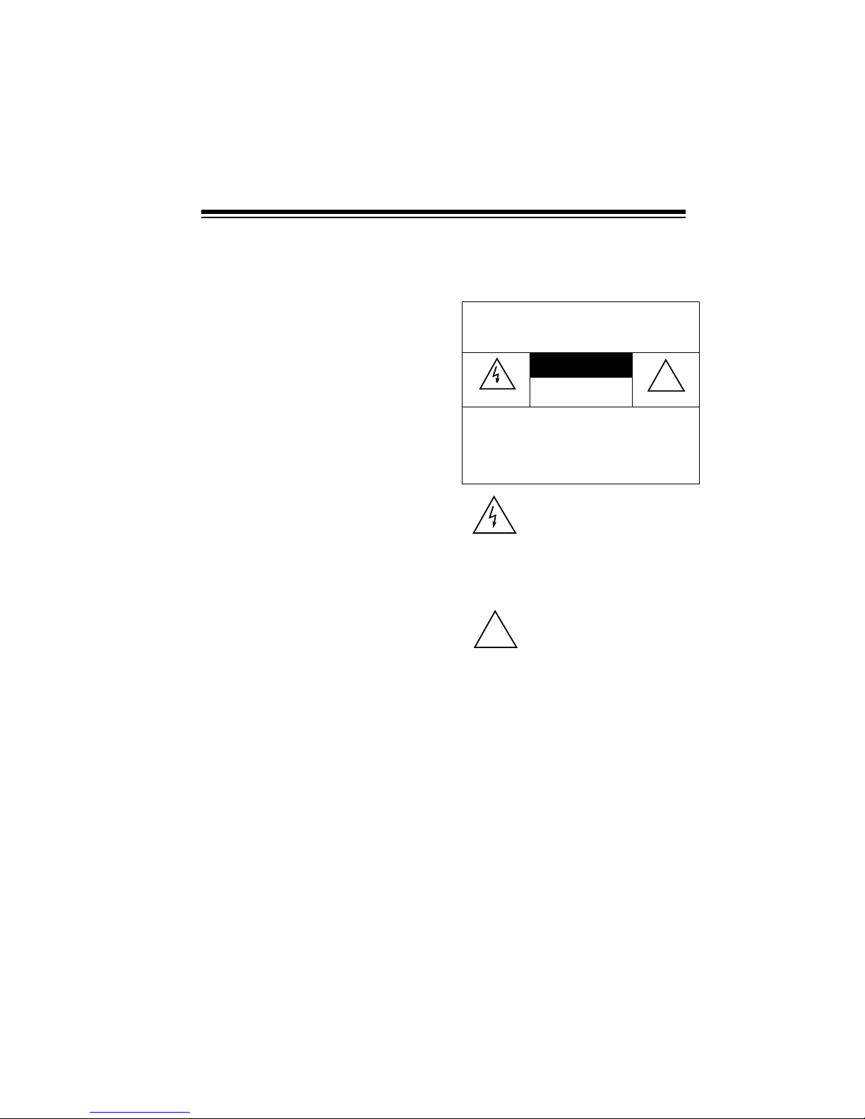
CAUTION
RISK OF ELECTRIC
SHOCK. DO NOT OPEN.
CAUTION
: TO REDUCE THE RISK OF
ELECTRIC SHOCK, DO NOT REMOVE
COVER OR BACK. NO USER-SERVICEABLE PARTS INSIDE. REFER SERVICING
TO QUALIFIED PERSONNEL.
This symbol is intended to alert
you to the presence of uninsulated dangerous voltage within
the product’s enclosure that
might be of sufficient magnitude
to constitute a risk of electric
shock. Do not open the product’s
case.
This symbol is intended to inform
you that important operating and
maintenance instructions are
included in the literature accompanying this product.
!
!

4
READ THIS BEFORE
INSTALLATION
Your console's teleph one dialer is de signed to conform to federal regulations, and you can connect it to mo st
telephone lines. However, each telephone or telephone device that you
connect to the telephone line draws
power from the telepho ne line. We refer to this power dr aw as the device's
ringer equivalence number, or REN.
The REN is on the bottom of the console.
If you use more than one telephone or
other device on the line, add up all the
RENs. If the total is more than five,
your telephones might not ring. In rural
areas, a total REN of three might im pair ringer operation. If ringer operation is impaired, remove one of the
devices from the line.
Note:
You must not connect your con-
sole to:
• coin-operated systems
• party-line systems
• most electronic key telephone
systems
Your console's tele phone dialer complies with Part 68 of
FCC Rules
. You
must, upon request, pr ovide the FCC
registration number and the REN to
your telephone company. Both numbers are on the bottom of the console.
THE FCC W ANTS Y OU TO
KNOW
In the unlikely ev ent that yo ur security
console dialer causes problems on the
phone line, the phone company can
temporarily discontinue your service.
If this happens, the phone company attempts to notify you in advance.
If advance notice is not pr actical, the
phone company notifies you as soon
as possible and advises you of your
right to file a complaint with the FCC.
Also, the phone company can make
changes to its lines, equipment, operations, or procedures that could affect
the operation of this telephone. The
telephone company notifies you of
these changes in advance, so you can
take the necessary steps to prevent interruption of your telephone service.

5
CONTENTS
Glossary.................................................................................................................7
Planning Your Security Sys tem....................... ....... ...... ....... ...... ....... ...... ...... ....... 8
Assigning Security Codes ............................................................................... 9
Reassigning Security Codes .............................................................. ...... ....... 9
Quick Installing/Testing Your Sys tem............................................................... 10
Setting Up The Console ................................................................................ 10
Installing the Keychain Remote Control ................................................... ..... 11
Installing the Handheld Remote Control ........................................................ 12
Initializing the Wireless Sensor Transmitters ................................................. 13
Initializing the Motion Sensor ............................. ...... ..................................... 14
Installing the Lamp Module ...................................... ....... ...... ........................ 15
Testing the System ........................................................................................ 16
Mounting Accessories ........................................... ........................................... 17
Mounting the Wireless Sensor Transmitters .................................................. 17
Mounting the Motion Detector ....................................................................... 18
Making a Pet Zone ........................................................................................ 20
Testing the Motion Detector .......................................................................... 20
SETTING UP THE TELEPHONE DIALER ......................................................... 22
Setting up Phone Numbers ........................................................................... 22
Recording a Voice Message ......................................................................... 24
Testing the Dialer .......................................................................................... 25
OPERATION ......................................... ....... ...... ....... ........................................... 26
Arming/Disarming the System ...................................................................... 26
Arm Away/Arm Home ............................................................................. 26
Instant/Delay Mode ................................................................................. 26
Using the Panic Alarm ................................................................................... 27
Zone Indicators ............................................................................................. 27
Reading the Status of Zones 1–8 ........................................................... 28
Trouble Alarm ......................................................................................... 28
Reading the Status of Zones 9–16 ......................................................... 28
Other Console Indicators ........................................................................ 29
During an Alarm ............................................................................................ 29
After an Alarm ............................................................................................... 29
Controling Plug ’N Power Modules ................................................................ 29
Turning Modules On/Off .......................................................................... 29
Using Security Light................................................................................. 30
Using Bright/Dim ..................................................................................... 30
Resetting the Console ................................................................................... 30

6
Troubleshooting ................................................................................................. 31
Care and Maintenance ....................................................................................... 36
Replacing the Console’s Battery ................................................................... 37
Replacing a Remote’s Batteries .................................................................... 37
Replacing a Wireless Sensor Transmitter’s Batteries .................................... 38
Intercom Systems .......................................................................................... 38
FCC Cautions ................................................................................................ 39
Lightning ...................... ................................................................ .................. 39

7
GLOSSARY
Here are a few terms th at w ill b e he lp ful to understand as you read this manual.
Arm and Disarm
— Terms for on and
off. When you arm the system, you
turn on protection. Disarming the system turns off protection.
Away Mode
— Your system’s armed
mode when all sensors (inc luding mo tion detectors) are armed.
Console
— The system’s main co ntrol
panel.
Entry/Exit Delay
— A setting on the
hand-held remote control that allows
you time while entering and exiting
your house before the syste m arms or
the alarm trips.
Home Mode
— The system’s armed
mode when only doors and windows
are armed (not motion detectors). This
prevents you from accidentally tripping
the motion detector(s) yours elf as you
move around the house.
Instant Mode
— A way of arming the
system so the alarm immedi ately trips
if a wireless sensor transmitter set to
INSTANT or the motion detector reports
an intrusion.
Note:
The keychain remote control
only arms the system in the instant
mode.
Motion Detector
— Senses motio n by
detecting a change in temperature
when an intruder walks across its path.
Remote Control
— A device that lets
you arm and dis arm the system a way
from the console.
Violation
— An alarm condition, s uch
as that caused by an open ed door or
window, detected by a sensor.
Wireless Sensor Transmitter
— Triggers the alarm when a secured door or
window opens.
Zone
— The area protected by a wireless sensor transmitter, a motion detector, or other sensing/transmitting
device.

8
PLANNING YOUR SECURITY SYSTEM
Before you set up your system, make a
security plan of your h ome . T hi s i s es pecially important if you install multiple
sensors to protect several different
zones.
Even if you only install the supplied
sensors, take time to think about the
best location for them. If you l ive in an
upstairs apartment, the front door
might be the best place to mount a
wireless sensor transmitter. If you live
in a house or downstairs apartment,
you might want to cover a ba ck door
and/or window.
Start by drawing a simp le floorplan of
your home, which you can use through
all stages of planning your system.
Your security system has three goals:
• to prevent loss by discouraging
potential intruders
• to scare intruders away before
they can take your property or
break into your home
• to alert you or others that someone is breaking into your home
To help accomplish these goals, you
should:
• Post decals on doors and windows stating that your home is
protected by a security system.
Decals (Cat. No. 49-507) are
available at your local RadioShack
store.
• Choose a location for the console
where it is not easily acc essi ble or
seen by intruders.
In addition, most police departments
offer information that might be help ful.
After making a prelimi nary plan, contact your local police department to
see if they offer guidelines or other services for planning a ho me security sy stem.

9
ASSIGNING SECURITY
CODES
A security zone is an area of protection
covered by a single wireless sensor
transmitter, motion detector, or other
sensing/transmitting device. Your security console monitors up to 16 zones
and alerts you if there is a violation
(see “Zone Indicators” on Page 27).
When you initia lize your security system’s sensors, the c onsole assigns a
zone number to the sensor (see “Initializing the Wireless Sensor Transmitters” on Page 13). The system
includes numbere d sti cke rs you at t ach
to each sensor to show its zon e number. For your reference, make a record
of which area of your home a zone
covers. For example, using the floorplan you drew, you could mark the
front door as “Zone 1.”
REASSIGNING
SECURITY CODES
If you want to rem ove one acce ssory,
reassign an accessory to a zone currently in use, or add an accessory
when all zones are assigned, you must
completely reinitialize the entire system.
To reinitialize the system, unplug the
console and remove its battery backup. The co nsole loses a ll st ored co des.
Then reinitialize all remote controls,
wireless sensor tran smitters, and motion detectors, ass igning each accessory to the desired zone.
10
QUICK INSTALLING/TESTING YOUR SYSTEM
This section describes how to initialize
all of the system’s accessories so they
are recognized by the console and
how to test the system to mak e sure it
is working properly. Perform all the
procedures in this sec tion, then follow
the instructions in “Mounting Accessories” on Page 17.
You can add other separately purchased accessorie s to the system by
following the appropriate initialization
and testing procedures in this section.
SETTING UP THE
CONSOLE
1. Choose a location for the console
that is:
• close to a telephone jack so you
can easily connect the telephone dialer
• central to the doors/windows
you want to protect so all sensors are within range of the
console (100 feet)
• positioned where you can easily
check the zone indicators for
any problems, but not where an
intruder could easily see it
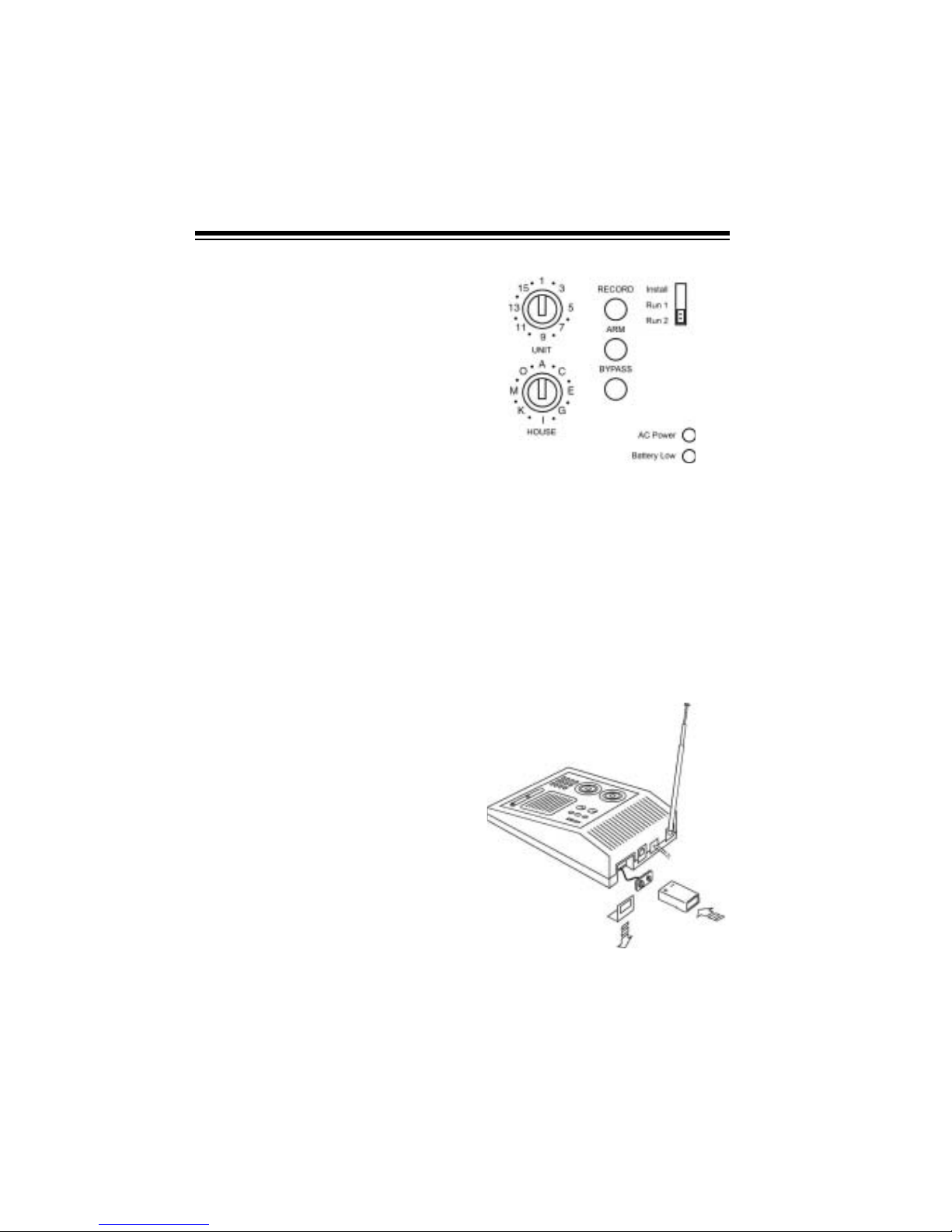
2. Set the house and unit code di als
on the console to
A1.
Note:
You can set the cons ole to
any house code, but you must
also set all accessories/sensors to
the same house code.
3. Place the telescoping antenna in
an upright position and fully
extend it.
4. For backup power in case of an
AC power failure, place a 9-volt
alkaline battery in the battery
compar tment. See “Replacing th e
Console’s Battery” on Page 37.
11
Note:
Be sure to install the
backup battery. If there is no battery and the console loses AC
power, you must re-initialize all of
the system’s accessories.
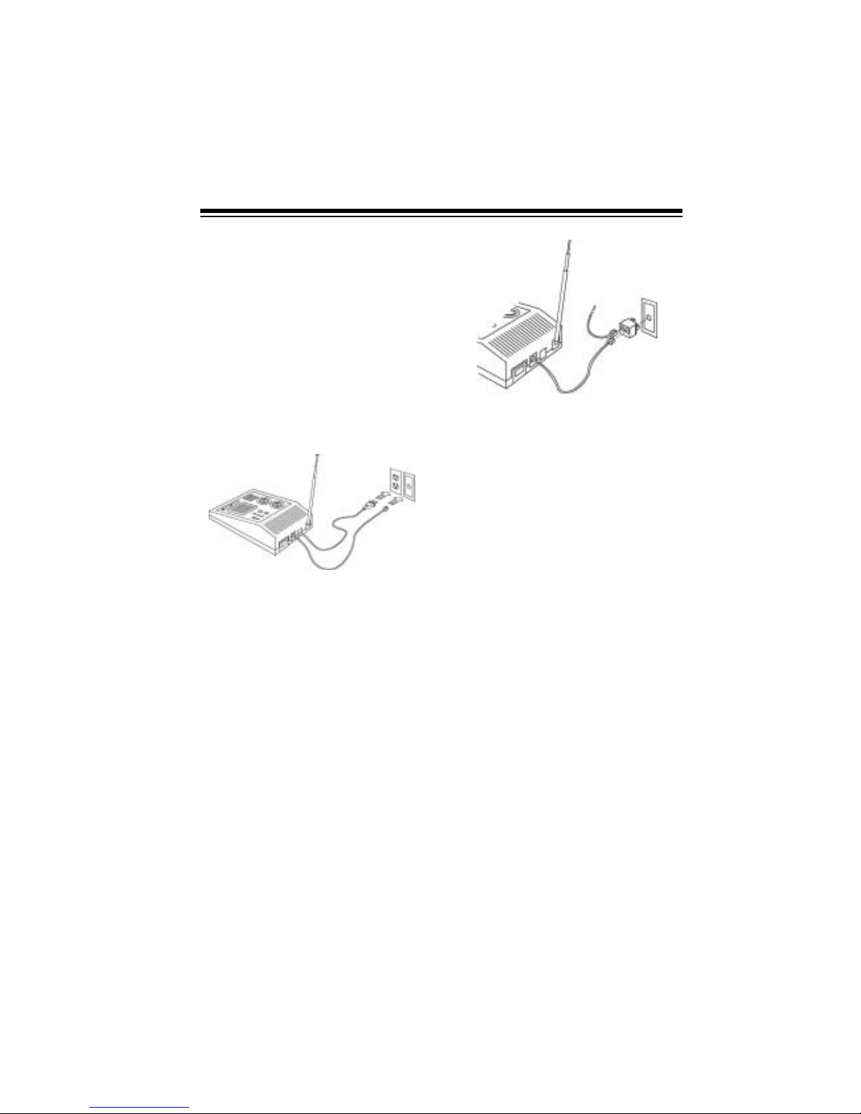
5. Plug the console into any standard AC outlet that is not controlled by an on/off switch.
6. Plug the telephone cord into the
console and plug the other end
into a modular phone jack.
Notes:
• If you do not have an unused jack,
use the supplied duplex adapter.
For a baseboard jack, plug the
adapter into the jack; for a wall
jack, plug the adapter into the
console.
• If you do not have a modular
phone jack, you can either updat e
the wiring yourself or have the
phone company do it for you.
RadioShack stores sell the jacks
and adapters you need. The
USOC number of the jack to be
installed is RJ11C for a baseboard
jack or RJ11W for a wall jack.
INSTALLING THE
KEYCHAIN REMOTE
CONTROL
1. Slide off the keychain remote c ontrol’s battery compartment cover.
Install two AAA alkaline batteries
in the compar tment, according to
the polarity symbols (+ and –)
marked inside. Then replace the
compar tme nt’s cover.
12
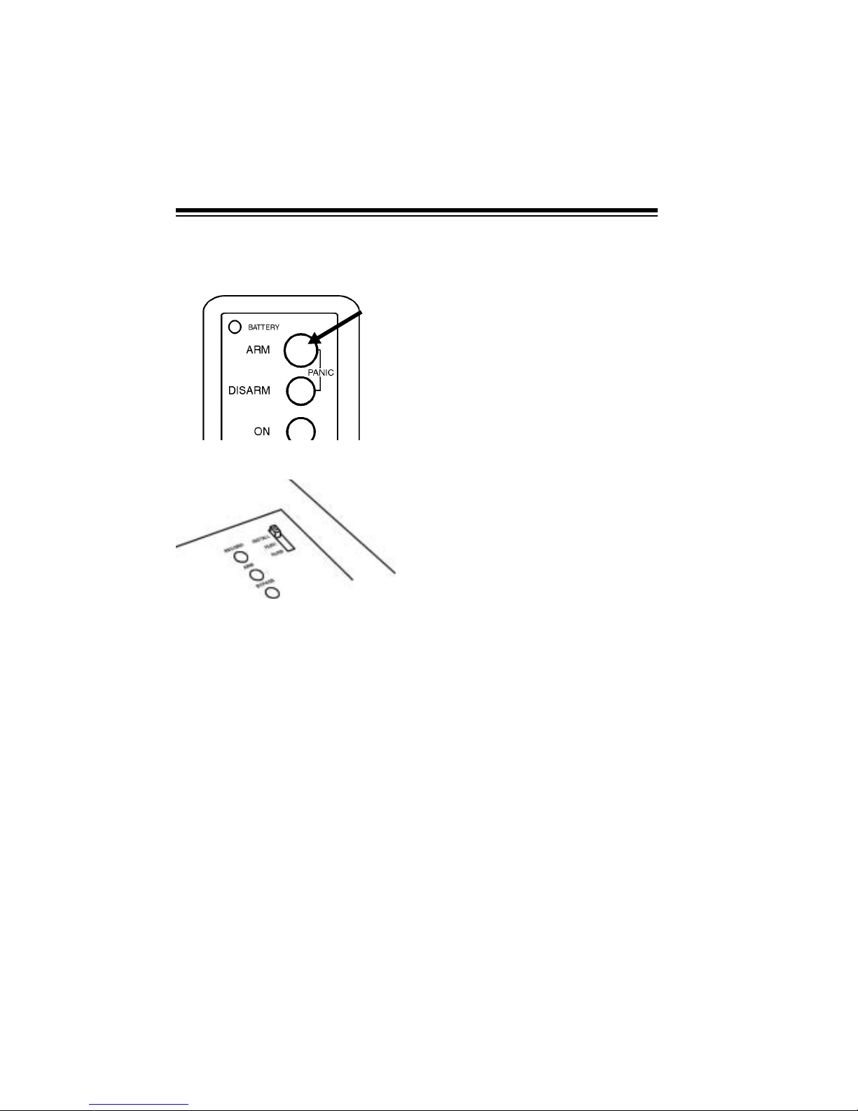
2. Press ARM on the remote control.
The indicator on the remote control blinks.
3. Set the console’s
INSTALL/RUN 1/
RUN 2
switch to INSTALL.
4. Stand near the console and pr ess
ARM again. The indicator blinks
again, and the console chimes
and logs in the remote control.
5. Leave the console’s switch set to
INSTALL to install other accesso-
ries.
Notes:
• You can add any combination of
up to eight Plug ’n Power
remote controls.
• When you press a button,
BAT-
TERY
lights on the remote c on-
trol to show the battery is good.
INSTALLING THE
HANDHELD REMOTE
CONTROL
1. Press the tab on the batter y compartment cover and lift off the
cover.
2. Install four AAA alkaline batteries
in the handheld remote control’s
battery compartment, according
to the polarity symbols (+ and –)
marked inside the compartment.
3. Be sure the console’s
INSTALL/
RUN 1/RUN 2
switch is set to
INSTALL.
4. Set the house code on the re mote
control to the same letter as the
console.
5. Press
ARM HOME or ARM AWAY
on the handheld remote control.
The console chimes.
Still Missing-Paste in
this illustration at
Proof to Mass Print
stage.
 Loading...