

Page 1

32-3008.fm Page 1 Thursday, April 6, 2000 4:03 PM
SSM-1750 4-Channel
Stereo Audio Mixer
Owner’s Manual
Please read before using this equipment.
Page 2
32-3008.fm Page 2 Thursday, April 6, 2000 4:03 PM
ˆ
Contents
Features .................................................................................................................................. 4
Preparation ............................................................................................................................. 6
Presetting the Controls ...................................................................................................... 6
Connecting the Outputs .................................................................................................... 6
Connecting Inputs ............................................................................................................. 6
Connecting Microphones ........................................................................................... 7
Connecting Power ............................................................................................................. 7
Connecting a Lamp ........................................................................................................... 7
Connecting Headphones ................................................................................................... 7
Listening Safely ......................................................................................................... 7
Operation ................................................................................................................................ 7
Presetting the Input Signal Levels ..................................................................................... 8
Presetting the Channel Inputs ................................................................................... 8
Presetting a Microphone ............................................................................................ 9
Presetting the Auxiliary Input ..................................................................................... 9
Mixing the Inputs ............................................................................................................. 10
Playing One Input Source ........................................................................................ 10
Monitoring a Second Input Source ........................................................................... 10
Switching to the Second Input Source ..................................................................... 11
Notes on Mixing ....................................................................................................... 11
Using the Special Controls .............................................................................................. 11
Using the Tone Controls ........................................................................................... 11
Using Gain ............................................................................................................... 11
Setting the Sound Balance ...................................................................................... 12
Using a Microphone ........................................................................................................ 12
Using an XLR Microphone ....................................................................................... 12
Using an AUX Microphone ....................................................................................... 12
Using TA LKO VER .................................... ... .................................... ......................... 12
Using MUTE LEVEL ................................ ... ............................................................. 12
Using P AN ................................................................................................................ 12
Using SOUND EFFECTS ................................................................................................ 12
Using ECHO EFFECTS .................................................................................................. 12
Adjusting the Echo Delay, Repeat, and Volume ...................................................... 13
Using Sound Effect Devices ............................................................................................ 13
Playing the Signal from the Sound Effect Device .................................................... 13
Playing Input Signals through the Sound Effect Device ........................................... 13
©
2000 Tandy Corporation.
RadioShack and RadioShack.com are trademarks used by Tandy Corporation.
2
All Rights Reserved.
Page 3
32-3008.fm Page 3 Thursday, April 6, 2000 4:03 PM
Care .................................................................................................................................. ..... 14
Replacing the Fuse ................................... ..................................... ................................. 14
Troubleshooting ................................................................................................................... 14
Specifications ...................................................................................................................... 15
WARNING:
shock hazard, do not expose this product to rain
or moisture.
To reduce the risk of fire or
CAUTION
RISK OF ELECTRIC SHOCK.
DO NOT OPEN.
CAUTION:
ELECTRIC SHOCK, DO NOT REMOVE
COVER OR BACK. NO USER-SERVICEABLE PARTS INSIDE. REFER SERVICING
TO QUALIFIED PERSONNEL.
!
TO REDUCE THE RISK OF
This symbol is intended to alert
you to the presence of uninsulated dangerous voltage within
the product’s enclosure that might
be of sufficient magnitude to constitute a risk of electric shock. Do
not open the product’s case.
This symbol is intended to inform
you that important operating and
maintenance instructions are
included in the literature accompanying this product.
!
3
Page 4
32-3008.fm Page 4 Thursday, April 6, 2000 4:03 PM
ˆ
Features
Your RadioShack 4-Channel Stereo Audio Mixer is a sophisticated control center, perfe ct for
mixing sound from multiple playback sources such as a microphone, tuner, CD player, turntable, or the audio output from a VCR.
It is ruggedly constructed for home or professional use and its wide-range volume controls let
you adjust sound levels to achieve the right mix for playing through your speaker system or for
recording. The mixer's many features give you almost limitless sound combinations.
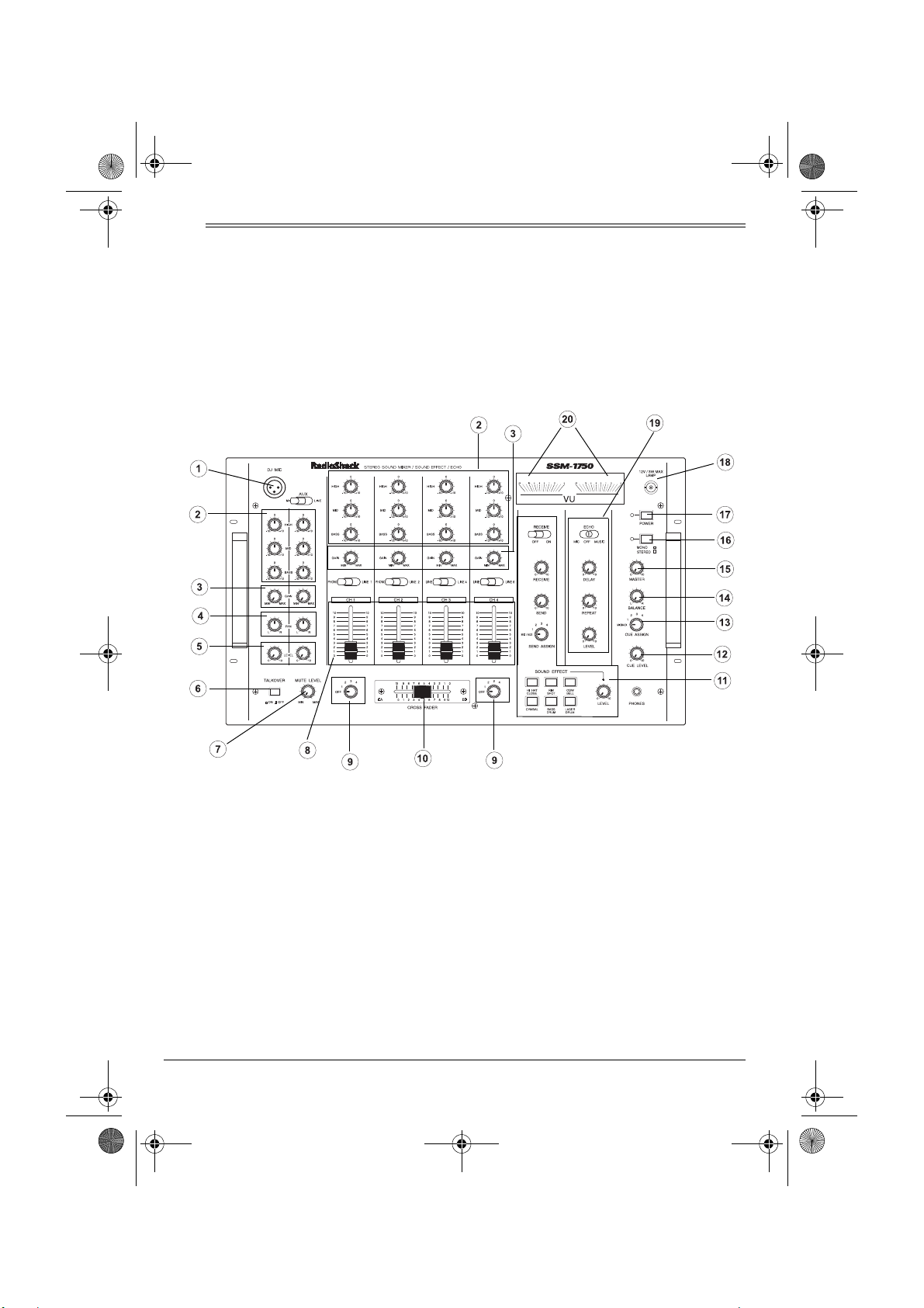
1
DJ MIC
— lets you connect a balanced,
low impedance microphone with an XLR
plug.
2
BASS/MID/HIGH
tone of the selected input for customized
sound.
3
4PAN
4
GAIN
— individual controls let you fine
tune each input’s volume.
— lets you control the output of the
DJ MIC
and
—
let you adjust the
AUX MIC/LINE
.
Features
5
6
7
8
LEVEL
phones' volumes before mixing them in.
TALKOVER
the input sources so you can talk over
them using the microphone.
MUTE LEVEL
ground music volume when using
OVER
CH1, CH2, CH3, CH4
trols
mixing and fading.
— lets you adjust the micro-
— decreases the volume of
— lets you adjust the back-
.
Slide Volume Con-
— for fingertip control of sound
TALK-
Page 5
32-3008.fm Page 5 Thursday, April 6, 2000 4:03 PM
9 Assign Controls—
let you select the in-
put sources to be mixed.
10
CROSS FADER
— lets you smoothly
switch between two input sources.
11
SOUND EFFECT
— let you create a special sound performance using the six
preprogrammed sound effects.
12
CUE LEVEL
— lets you adjust the head-
phone's volume.
13
CUE ASSIGN
— lets you select the channel where the desired audio input source
is located so you can monitor and prepare it before mixing it in.
14
BALANCE
—
lets you adjust the sound
balance between the left and right
speakers.
15
MASTER
DJ MIG, AUX, CH1, CH2, CH3, CH4, RECEIVE
16
MONO/STEREO
— adjusts the overall volume of
input, and sound effects.
Selector
— lets you set
the output to stereo or monaural.
17
POWER
18 Lamp Jack
—
turns the mixer on and off.
— lets you install a 12V/3W
lamp to light up the mixer controls.
19
Controls —
ECHO
let you tailor the
sound to compensate for a location’s
conditions or for personal preference.
(Volume Unit) —
20
VU
two meters indi-
cate the total stereo output signal levels.
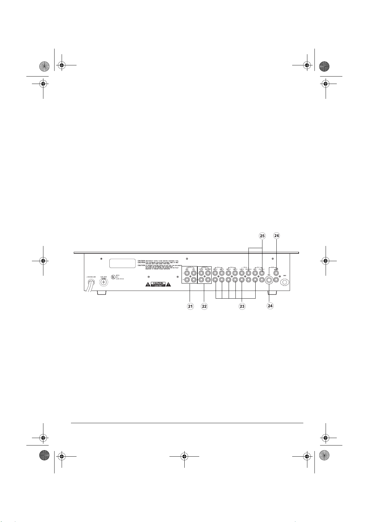
21 Stereo Line Outputs
— let you connect
the mixer's output to your receiver/amplifier and tape deck so you can play the
sounds from your input sources through
your speaker system, and record them.
22 Sound Effect Jacks
— let you connect
another sound effect device, such as an
echo reverb, and either play the signal
from it or play another input's signal
through it. You can also vary the volume
of the signal.
23 Stereo Line Inputs —
let you connect
most line-level audio sources such as a
CD player, tape deck, tuner, camcorder,
or VCR.
24 Auxiliary Microphone Input
connect a low impedance microphone
1
/4-inch plug.
with a
25 Stereo Phono Inputs
low-level audio sources, such as a turntable with a magnetic cartridge.
26 Mono Line Input
mono input source, such as a wireless
microphone receiver.
Features
— lets you
— for connecting
— lets you connect a
5
Page 6

32-3008.fm Page 6 Thursday, April 6, 2000 4:03 PM
ˆ
Preparation
PRESETTING THE
CONTROLS
Warning:
mixer could damage your hearing, especially
if you use headphones, and might also damage the audio devices connected to the mixer's output. Before using the mixer, make
sure you set your receiver/amplifier's volume
control to its minimum volume level setting.
Before you connect the power cord, make
sure you set
and inaudible sound outputs from any audio
devices that you connect to the mixer, be
sure to have their power controls set to off,
and any tone controls set to flat.
A sudden high output from the
POWER
to off. To avoid sudden
CONNECTING THE
OUTPUTS
To play the mixer's output signal through
your sound system (for events such as parties, dances, conferences, and so on), connect one end of an audio patch cord (not
supplied) to the mixer's
(white) and R (red) jacks, then connect the
other end to your receiver/amplifier's left and
right input jacks, matching left to left, and
right to right.
To record the mixer's output signal, connect
one end of an audio patch cord (not supplied) to the mixer's
R
(red) jacks, then connect the other end
and
to your tape deck's left and right line input
jacks, matching left to left, and right to right.
OUTPUT AMP L
OUTPUT REC L
(white)
CONNECTING INPUTS
You can connect up to ten audio input sources (such as cassette tape decks, CD players,
tuners, two magnetic-cartridge turntables, a
camcorder or a VCR) to the mixer’s input
jacks on the back panel. You can also connect microphones to the appropriate jacks on
the top and back panels.
1. Connect the line-level outputs from up to
six audio sources to the
LINE 3, LINE 4, LINE 5
jacks, matching left to left, and right to
right.
Caution:
source with a line-level output to the
low-level
MIC
2. Connect the low-level outputs from up to
two audio sources (such as magnetic
cartridge turntables) to the
PHONO 2
left, and right to right.
Note:
turntables, connect their ground wires
(usually black or green) to
3. Connect a sound effect device (such as
an echo reverb or a digital sampler processor) to the
and
matching left to left, and right to right.
4. Connect a mono input source (such as a
wireless microphone receiver) to the
AUX LINE MONO
left, and right to right.
Do not connect an audio
PHONO 1, PHONO 2
audio input jacks.
input jacks, matching left to
If you connect magnetic cartridge
EFFECT SEND
EFFECT RECEIVE
jacks, matching left to
LINE 1, LINE2
LINE 6
, and
, or
PHONO 1
GND
.
(output)
(input) jacks,
input
AUX
and
,
6
Preparation
Page 7
32-3008.fm Page 7 Thursday, April 6, 2000 4:03 PM
Connecting Microphones
You can connect two microphones (not supplied) to the mixer.
Connect a microphone with an XLR plug to
DJ MIC
on the top panel’s upper left corner.
1
Connect a microphone with a
mm) plug to
lower right corner.
AUX MIC
on the back panel’s
/4-inch (6.35
CONNECTING POWER
Note:
Before you connect the mixer's power
cord, make sure power is turned off by press-
POWER
ing
off).
Connect the power cord to a standard AC
outlet.
Caution:
plug that fits only one way into a standard AC
outlet. If the plug does not fit, turn it over so it
fits properly. Do not force it!
(if the control is out, the power is
The power cord has a polarized
CONNECTING A LAMP
The mixer has a
for connecting a 12V/3W BNC lamp so you
can see the control panel in dark or low light
conditions.
12V/3W MAX LAMP
socket
CONNECTING
HEADPHONES
To listen in privacy or monitor the audio
source inputs so you can locate an exact
passage or section before mixing it, connect
a pair of stereo headphones (not supplied)
1
/4-inch (6.35 mm) plug to the
with a
jack on the mixer's lower right corner.
Your local Radio Shack store carries a wide
selection of headphones.
Listening Safely
Do not listen at extremely high volume levels. Extended, high-volume listening can
lead to permanent hearing loss.
To protect your hearing when you use headphones, always follow these guidelines to set
the listening volume.
CUE LEVEL
•Set
tening.
• After you put on the headphones, adjust
CUE LEVEL
volume level.
• Once you set the headphones' volume,
do not increase it. Over time, your ears
adapt to the volume level, so a volume
level that does not cause discomfort
might still damage your hearing.
to 0 before you begin lis-
to a comfortable listening
PHONES
ˆ
Operation
1. Set the volume levels on the output
devices (receiver, amplifier, or tape
deck) to minimum and turn them on.
2. Press
3. Turn on the input sources you want to
POWER
POWER indicator lights.
mix.
to turn on the mixer. The
Operation
4. Preset the input signal levels (see “Presetting the Input Signal Levels” on
Page 8).
5. Mix the audio input sources (see “Mixing
the Inputs” on Page 10).
7
Page 8

32-3008.fm Page 8 Thursday, April 6, 2000 4:03 PM
6. After you finish mixing, turn down the
volume on the output audio devices, turn
off the input and output audio devices
(amplifiers, tape decks, and so on), then
press
POWER
so it pops up to turn off
the mixer. The POWER indicator turns
off.
PRESETTING THE INPUT
SIGNAL LEVELS
To avoid accidentally over-driving a channel
or prematurely mixing in an audio input
source, start with the following settings:
• All volume slide controls set to 0.
• Both
GAIN
•All
HIGH
•All
LEVEL
SEND, RECEIVE
Rotate
MASTER
ASSIGN
switches set to
knobs set mid level.
MID
,
DJ MIC LEVEL, AUX LEVEL
,
, and
, and
BASS
MASTER
clockwise and temporarily
set it to about the 5th marker.
Note:
the overall volume of
CH3, CH4, RECEIVE
The
MASTER
volume control adjusts
DJ MIC, AUX, CH1, CH2
input, and sound effects.
The mixer uses two volume unit (VU) meters
to indicate the total stereo output signal level.
For the best results, each input signal level
should normally be set so the VU meters
never move into the red range (
Distortion is likely to occur on audio peaks if
the meter moves into the red range.
For monaural output, set
MONO
. For stereo output, set it to
Presetting the Channel Inputs
Follow these steps to preset each channel
input you plan to mix.
OFF
.
controls,
MONO/STEREO
set to
0
or above).
STEREO
CUE
0.
to
.
Notes:
• If you did not connect an input source to
every jack or do not want to mix every
input source connected to the mixer's
input jacks, you do not need to preset
every channel input. Decide which
source(s) you want to preset and mix,
then preset those inputs only.
• While you adjust the input signal levels
for channels 1, 2, 3, and 4, either use
the headphones or turn up the receiver/
amplifier's volume to a comfortable listening level (not necessarily the final
usable level).
• Do not play a quiet portion of music
while you adjust the volume levels, otherwise the volume levels for channels 1,
2, 3, and 4 will be over-driven during the
loud portions of the music.
,
1. Set the channel selector to the desired
input source.
2. Start playback of the selected input
source.
,
3. Adjust the
HIGH, MID
, and
BASS
as desired. See “Using the Tone Controls” on Page 11.
Note:
If you are using an external equalizer, leave the tone controls set to
adjust the tone on the external equalizer.
4. Slowly slide up the channel volume control until you get a reading of up to
both VU meters.
Important:
Note the channel volume level
slide control's setting for the selected audio
source, so each time you want to mix that
source you can slide the volume control to
the correct setting.
controls
0
and
0
on
8
Operation
Page 9

32-3008.fm Page 9 Thursday, April 6, 2000 4:03 PM
Notes:
• If it was necessary to set the channel
10
volume level slide control to
to get a
reading of up to 0 on the VU meter, then
8
slide it down to about
GAIN
control to get a reading of up to
and adjust the
on the VU meters. (See “Using Gain” on
Page 11.)
• If the above does not work, set
mid level and rotate
until you get a reading of
GAIN
MASTER
clockwise
0
on the VU
meters.
• Readjusting
the previously set input sources.
MASTER
affects the level of
must readjust those sources until you
get a reading of up to 0 on the VU
meters for each input source.
5. Stop playback of the selected input
source.
6. Repeat these steps for each channel
input you plan to mix.
Presetting a Microphone
to
You
Notes:
• If it was necessary to set
AUX LEVEL
or
all the way to 10 in order
to get a reading of up to 0 on the VU
meter, then turn it down to about
0
adjust the
DJ MIC GAIN
control to get a
reading of up to 0 on the VU meters.
(See “Using Gain” on Page 11.)
If that does not work, set
AUX GAIN
TER
0
on the VU meters.
• If you must readjust
to mid level and rotate
clockwise until you get a reading of
MASTER
ber, doing so affects the level of the previously set input sources. You must
readjust those sources until you get a
0
reading of up to
on the VU meters for
each input source.
3.If your XLR or auxiliary microphone has
an ON/OFF control, set it to OFF.
If your XLR or auxiliary microphone
does not have an ON/OFF control, set
DJ MIC LEVEL
AUX LEVEL
or
DJ MIC LEVEL
8
and
DJ MIC GAIN
MAS-
, remem-
to 0.
or
1. If your XLR or auxiliary microphone has
an ON/OFF control, set it to ON.
If your XLR or auxiliary microphone
does not have an ON/OFF control, set
DJ MIC LEVEL
2. While talking continuously, adjust
LEVEL
or
reading of up to
AUX LEVEL
or
AUX LEVEL
0
on both VU meters.
to 0.
DJ MIC
until you get a
(See “Using an XLR Microphone” on
Page 12 and “Using an AUX Microphone” on Page 12.)
Important:
LEVEL
Note the
setting, so each time you want to mix
DJ MIC LEVEL
or
AUX
the microphone, you can set the control to
the correct setting.
Operation
Presetting the Auxiliary Input
1. To preset the
AUX
to
2. Start playback of the selected input
source.
3. Adjust the
as desired. See “Using the Tone Controls” on Page 11.
Note:
If you are using an external equalizer, leave the tone controls set to
adjust the tone on the external equalizer.
4. Slowly adjust
reading of
AUX LINE
LINE
.
HIGH, MID
0
on both VU meters.
, and
AUX LEVEL
input source, set
BASS
controls
0
until you get a
and
9
Page 10

32-3008.fm Page 10 Thursday, April 6, 2000 4:03 PM
Important:
Note the
AUX LEVEL
setting,
so each time you want to mix that
source you can set the control to the
correct setting.
Notes:
• If it was necessary to set the
AUX LEVEL
control to 10 to get a reading of up to
on the VU meter, then set
about 8 and adjust the
AUX LEVEL
AUX GAIN
to
control
to get a reading of up to 0 on the VU
meters. (See “Using Gain” on Page 11.)
• If the above does not work, set
GAIN
mid level and rotate
AUX
MASTER
clockwise until you get a reading of 0 on
the VU meters.
• Readjust
MASTER
affects the level of the
previously set input sources. You must
readjust those sources until you get a
0
reading of up to
on the VU meters for
each.
5. Stop playback of the selected input
source.
MIXING THE INPUTS
You can connect input signals from up to 12
audio sources, select any two of the channel
input sources, then mix them so only one or
both play through your sound system.
Mixing requires three operations:
• Playing one input source.
• Monitoring the next input source.
• Switching to the next input source.
You can start with either of the two selected
sources.
To prevent prematurely mixing audio sourc-
0
es, set all volume level controls to
.
To avoid sudden and inaudible sound outputs from any audio devices that you connect to the mixer, be sure to set their power
controls to off and any tone controls to flat.
Playing One Input Source
1. Set
0
2. Select the mixer's input —
3. Set the input selector control to the input
4. Adjust the receiver's or amplifier's (not
5. Start playback of the input source.
ASSIGN A
then set
CH 3
, or
to the desired source,
CROSS FADER
CH 4
.
to A.
source you want to play first through
your sound system.
the mixer's) volume control to the
desired volume.
Make sure the first input source's volume level slide control is set to the correct preset position.
Monitoring a Second Input Source
Monitoring a second input source's signal
level requires selecting the input source that
is not currently playing, finding the desired
section you want to mix, then adjusting the
source's sound level so it matches the volume level of the source currently playing.
1. Connect and put on headphones.
Note:
You can listen to one channel
through the headphones while the other
channel is playing through the sound
system.
2. Set
ASSIGN B
source.
3. Set
CUE ASSIGN
source (
CH 1, CH 2, CH 3
want to monitor.
to the second input
to the audio input
, or
CH 1, CH 2
CH 4
) you
,
10
Operation
Page 11

32-3008.fm Page 11 Thursday, April 6, 2000 4:03 PM
4. Set the desired channel volume level
slide control to the preset position.
5. Adjust
CUE LEVEL
to a comfortable lis-
tening level.
6. Start playback of the input source you
want to play next through your sound
system.
7. Set the input device to the desired section of music, then stop or pause the
input device.
Switching to the Second Input
Source
1. Start playback of the second input
source.
2. Slide
CROSS FADER
from A to B when
you are ready to play the second
source’s sound through your sound system.
CROSS FADER
Slide
:
• To the left to fade in the channel
selected by
ASSIGN A
the channel selected by
and fade out
ASSIGN B
• To the right to fade in the channel
selected by
ASSIGN B
the channel selected by
center
• To the
to equally mix the two.
and fade out
ASSIGN A
Notes on Mixing
• If you set
channel selected by
must set
CH 1
monitor
4
. The same applies when you set
CROSS FADER
CROSS FADER
CUE ASSIGN
CH 2
, to
CH 3
ASSIGN A
to
to monitor
, and to
CH 4
to B.
to A to play the
, then you
CH 1
to monitor
CH 2
, to
CH 3
to monitor
.
.
• To mix any two inputs selected by the
ASSIGN
switches, set each
switch to the desired channel. Then use
CROSS FADER
• Do not slide
if you want to
to mix the two.
CROSS FADER
monitor
one channel while
the other is playing. Otherwise, the
sound from the channel you monitor will
also be heard through your sound system. Instead, slide
CROSS FADER
channel you are not monitoring. For
example, to monitor channel 1 (selected
ASSIGN A
by
ASSIGN B
by
FADER
CUE LEVEL
• Use
controlled by the
) while channel 2 (selected
) is playing, slide
to B.
to listen to the input
CUE ASSIGN
and what is playing on the currently
selected output device.
USING THE SPECIAL
CONTROLS
Using the Tone Controls
Your mixer has a set of tone controls for
each microphone and for channels 1–4. You
can tailor the high, middle, and low frequency sounds for each.
For normal sound, leave
HIGH
set to 0.
HIGH, MID
Rotate
crease, or toward
or
–10
crease the high, middle, and low frequency
sounds.
Using Gain
to
CH
Since the input levels of each sound source
are different, the
GAIN
tune each selected input's volume. Rotate
GAIN
the desired
control toward
crease the volume and toward
it.
BASS, MID
BASS
toward
respectively to de-
controls let you fine
ASSIGN
to the center
to the
CROSS
switch
, and
+10
to in-
MAX
to in-
MIN
to reduce
Operation
11
Page 12
32-3008.fm Page 12 Thursday, April 6, 2000 4:03 PM
Note:
We recommend you not adjust the
GAIN
controls after you have preset the in-
puts as some sound imbalance could occur.
Setting the Sound Balance
BALANCE
between the left and right speakers. If your
speakers are properly positioned and your
listening area is centered between the
speakers, the center setting of the control is
usually the best.
If the sound seems to be louder from one
speaker, adjust
seems to be coming from a point midway between the speakers.
lets you adjust the sound balance
BALANCE
until the sound
USING A MICROPHONE
Using an XLR Microphone
To mix the microphone connected to the
XLR jack with other audio input sources, ad-
DJ MIC LEVEL
just
the microphone volume without affecting the
volume of the other inputs.
to increase or decrease
Using TALKOVER
To use the microphone and reduce other audio inputs so the microphone can be heard
more clearly, set
To turn off
OFF
. All the audio inputs including
AUX MIC
and
TALKOVER
TALKOVER
play at the same output level,
to ON.
, set T
ALKOVER
DJ MIC
to
and the background music volume is not reduced.
Using MUTE LEVEL
To increase background music when using
TA LK O VE R
, rotate
MUTE LEVEL
toward
MIN
To reduce background music, rotate it to-
MAX
ward
.
Using PAN
To play either microphone or the
output on the left or right channel, adjust the
appropriate
PAN
control. Set it to L to play
through the left channel, to
the right channel, or to any other position be-
L
tween
and R to play through both channels.
AUX LINE
R
to play through
.
DJ MIC LEVEL
Set
to 0 when you are not using the DJ microphone. Or, if the microphone
has an ON/OFF control, set it to OFF and
leave
DJ MIC LEVEL
at its preset position.
Using an AUX Microphone
To mix a microphone connected to the
MIC
jack with other audio input sources, set
AUX MIC/LINE
to
MIC
. Adjust
AUX LEVEL
increase or decrease the microphone volume without affecting the volume of the other
inputs.
AUX
When you are not using an
AUX MIC/LINE
set
to
LINE
microphone,
. This lets you mix
the output from the device connected to
LINE MONO
12
jacks.
AUX
to
AUX
Operation
USING SOUND EFFECTS
There are six preprogrammed sound effects
for your mixing selection — a hi-hat close, a
rim shot, a cow bell, a cymbal, a bass drum,
and a laser drum.
To play a sound effect, repeatedly press or
hold down the desired
SOUND EFFECT
but-
ton.
SOUND EFFECT LEVEL
Rotate
left or right to
increase and decrease the sound effect volume.
USING ECHO EFFECTS
The mixer plays echo effects, and lets you
adjust the echo delay, the number of echo
repeats, and the echo's volume.
Page 13
32-3008.fm Page 13 Thursday, April 6, 2000 4:03 PM
The echo is applied to the sound before al l
the inputs are mixed.
ECHO
Set
for the microphones and the
ECHO
Set
to
to
MIC
to turn on the echo effect
AUX LINE
MUSIC
to turn on the echo effect
input.
for Channels 1, 2, 3, and 4 outputs.
To turn off the echo effect, set
ECHO
to
OFF
Adjusting the Echo Delay , Repe at,
and Volume
ECHO DELAY
The
time delay for an echo. Set
for a minimum time delay and to 10 for a
maximum time delay.
ECHO REPEAT
The
the length of time a tone is repeated (reverberation). Set
longest time repeat and to 0 for the shortest.
ECHO LEVEL
The
output level of the echo effect. Rotate
LEVEL
toward 10 to increase the echo level
and toward 0 to decrease it.
control lets you adjust the
ECHO DELAY
control lets you control
ECHO REPEAT
to 10 for the
control lets you adjust the
to
ECHO
Playing Input Signals through the
Sound Effect Device
You can play inputs selected by the channel
selectors,
DJ MIC
sound effect devices connected to the mixer,
such as an echo reverb or a digital sampler
processor, and control playback through the
mixer. To play selected inputs through the
.
sound effect device, set
selected input.
SEND
The
control lets you adjust the volume
of the selected sound to the sound effect device without changing the device's volume.
0
Rotate
SEND
toward 10 to increase the vol-
ume and toward 0 to decrease it.
AUX
, or
SEND ASSIGN
through other
to the
USING SOUND EFFECT
DEVICES
Playing the Signal from the Sound
Effect Device
To play signals from a device connected to
EFFECT
the
ON
. When you are not using the connected
inputs, set the
Rotate
jacks, set the
RECEIVE
RECEIVE
to adjust the volume of the
input connected to the
changing the sound effect device's volume.
Rotate
RECEIVE
toward 10 to increase the
volume and toward 0 to decrease it.
RECEIVE
switch to
EFFECT
switch to
OFF
.
jacks without
Operation
13
Page 14
32-3008.fm Page 14 Thursday, April 6, 2000 4:03 PM
ˆ
Care
To enjoy your mixer for a long time:
• Keep the mixer dry. If it gets wet, wipe it
dry immediately.
• Use and store the mixer only in normal
temperature environments.
• Handle the mixer gently and carefully.
Do not drop it.
• Keep the mixer away from dust and dirt.
• Wipe the mixer with a damp cloth occa-
sionally to keep it looking new.
Modifying or tampering with the mixer’s internal components can cause a malfunction
and might invalidate its warranty. If your mixer is not performing as it should, take it to
your local RadioShack store for assistance.
ˆ
Troubleshooting
We do not expect you to have any problems with your mixer, but if you have a problem, this information might help. If the problem persists, take the mixer to your local RadioSha ck store for
assistance.
REPLACING THE FUSE
Your mixer requires a 250-volt, 0.5-amp fuse
to protect it from power surges and short circuits. If the mixer suddenly turns off or will
not turn on, the fuse could be blown. Replace
the fuse with a 0.5-amp, 250volt, fast-acting,
1
/4 x 1/4 inch fuse (not supplied).
1
Follow these steps to replace the fuse.
1. Using a Phillips screwdriver, unscrew
the fuse compartment cap on the back
of the mixer.
2. Remove the old fuse and replace it with
an identical fuse.
Caution:
type or rating.
3. Replace the fuse compartment cap.
Never use a fuse of a different
Problem Possible Solution
The mixer does not work. Check the AC power connection and make sure the AC outlet is
No signal from an audio input
sources.
You are getting a hum from the
PHONO sources.
14
“live.”
Check the power connection to the rest of the system (amplifier/
receiver, input sources, and so on).
Check the fuse. See “Replacing the Fuse” on Page 14.
Make sure the
Check the mixer’s and the source’s control settings.
Check the connection between the mixer and the input source.
Make sure the turntable’s ground wire (usually black or green) is
connected to the
TALKOVER
GND
Care
switch is set to
screw on the back of the mixer.
OFF
.
Page 15

32-3008.fm Page 15 Thursday, April 6, 2000 4:03 PM
Problem Possible Solution
Y ou are getting a hum from other
input source
Y ou are getting feedback noise. Move the microphone further away from the output speakers or use
ˆ
Specifications
Input Sensitivity/Impedance
DJ MIC (XLR jack) ............................................................. 1.5 mV, 600 ohms, Balanced/Unbalanced
AUX MIC (Phone jack) ....................................................................... 1.5 mV, 600 ohms, Unbalanced
Phono ......................................................................................................................... 3 mV/50 kOhms
Line ........................................................................................................................ 150 mV/27 kOhms
Output Level
Main Out ......................................................................................................................... 2V/10 kOhms
Record .................................................................................................................... 150 mV/10 kOhms
Send ....................................................................................................................... 150 mV/10 kOhms
Frequency Response ................................................................................................ 20–20k Hz ±3 dB
S/N Ratio
Mic ............................................................................................................................................... 55 dB
Phono .......................................................................................................................................... 65 dB
Line ............................................................................................................................................. 75 dB
Distortion
Mic .............................................................................................................................................. 0.20%
Phono ......................................................................................................................................... 0.08%
Line ............................................................................................................................................ 0.05%
Tone Control, DJ MIC, AUX, CH 1, CH 2, CH 3, CH4
HIGH Boost/Cut Range .............................................................................................. ±10dB at Center
MID Boost/Cut Range ................................................................................................ ±10dB at Center
BASS Boost/Cut Range ............................................................................................. ±10dB at Center
ECHO Delay Time .............................................................................................................. 50 –120ms
TALKOVER Attenuation ................................................................................................... –8 to –38 dB
Power Source ......................................................................................................... AC 120V, 60Hz, 20 Watt
Power Fuse ..................................................................................................................... 0.5 Amp/250 Volts
Dimensions (HWD).................................................................................................... 4
Weight ......................................................................................................................................... 11 Ibs 6 oz
Make sure there are no low-level inputs connected to the
jacks.
a unidirectional microphone.
(113 × 482 × 280 mm)
LINE
input
7
/16 × 19 × 11 Inches
(5.15 kg)
Specifications are typical; individual units might vary. Specifications are subject to change and improvement without notice.
Specifications
15
Page 16

32-3008.fm Page 16 Thursday, April 6, 2000 4:03 PM
Limited One-Year Warranty
This product is warranted by RadioShack against manufacturing defects in material and workmanship under normal use for one (1) year from the date of purchase from Radi oSha ck company- owned
stores and authorized RadioShack franchisees and dealers. EXCEPT AS PROVIDED HEREIN, RadioShack MAKES NO EXPRESS WARRANTIES AND ANY IMPLIED WARRANTIES, INCLUDING
THOSE OF MERCHANTABILITY AND FITNESS FOR A PARTICULAR PURPOSE, ARE LIMITED
IN DURATION TO THE DURATION OF THE WRITTEN LIMITED WARRANTIES CONTAINED
HEREIN. EXCEPT AS PROVIDED HEREIN, RadioShack SHALL HAVE NO LIABILITY OR RESPONSIBILITY TO CUSTOMER OR ANY OTHER PERSON OR ENTITY WITH RESPECT T O ANY
LIABILITY, LOSS OR DAMAGE CAUSED DIRECTLY OR INDIRECTLY BY USE OR PERFORMANCE OF THE PRODUCT OR ARISING OUT OF ANY BREACH OF THIS WARRANTY, INCLUDING, BUT NOT LIMITED TO, ANY DAMAGES RESULTING FROM INCONVENIENCE, LOSS
OF TIME, DATA, PROPERTY, REVENUE, OR PROFIT OR ANY INDIRECT, SPECIAL, INCIDENTAL, OR CONSEQUENTIAL DAMAGES, EVEN IF RadioShack HAS BEEN ADVISED OF THE
POSSIBILITY OF SUCH DAMAGES.
Some states do not allow limitations on how long an implied warranty lasts or the exclusion or limit ation of incidental or consequential damages, so the above limitations or exclusions may not apply to
you.
In the event of a product defect during the warranty period, take the product and the RadioShack
sales receipt as proof of purchase date to any RadioShack store. RadioShack will, at its option, unless otherwise provided by law: (a) correct the defect by product repair without charge for parts and
labor; (b) replace the product with one of the same or similar design; or (c) refund the purchase
price. All replaced parts and products, and products on which a refund is made, become the property of RadioShack. New or reconditioned parts and products may be used in the performance of
warranty service. Repaired or replaced parts and products are warranted for the remainder of the
original warranty period. You will be charged for repair or replacement of the product made after the
expiration of the warranty period.
This warranty does not cover: (a) damage or failure caused by or attributable to acts of God, abuse,
accident, misuse, improper or abnormal usage, failure to follow instructions, improper installation or
maintenance, alteration, lightning or other incidence of excess voltage or current; (b) any repairs
other than those provided by a RadioShack Authorized Service Facility; (c) consumables such as
fuses or batteries; (d) cosmetic damage; (e) transportation, shipping or insurance costs; or (f) costs
of product removal, installation, set-up service adjustment or reinstallat i on.
This warranty gives you specific legal rights, and you may also have other rights which vary from
state to state.
RadioShack Customer Relations, 200 Taylor Street, 6th Floor, Fort Worth, TX 76102
We Service What We Sell
12/99
RadioShack
A Division of Tandy Corporation
Fort Worth, Texas 76102
32-3008
04A00
Printed in China
 Loading...