

Cat. No.
15-1170
OWNER’S MANUAL
Please read before using this equipment
Satellite/TV/FM In-Line
Signal Amplifier
15-1170.fm Page 1 Tuesday, July 13, 1999 4:35 PM
2
WARNING:
To reduce the risk of fire or shock
hazard, do not expose this product to rain or
moisture.
CAUTION
RISK OF ELEC-
TRIC SHOCK. DO
NOT OPEN.
CAUTION:
TO REDUCE THE RISK OF ELECTRIC SHOCK, DO NOT REMOVE COVER OR
BACK. NO USER-SERVICEABLE PARTS
INSIDE. REFER SERVICING TO QUALIFIED
PERSONNEL.
!
This symbol is intended to alert
you to the presence of uninsulated dangerous voltage within
the product’s enclosure that might
be of sufficient magnitude to constitute a risk of electric shock. Do
not open the product’s case.
This symbol is intended to inform
you that important operating and
maintenance instructions are
included in the literature accompanying this product.
!
©
1999 Tandy Corporation.
All Rights Reserved.
RadioShack is a registered trademark used by Tandy Corporation.
15-1170.fm Page 2 Tuesday, July 13, 1999 4:35 PM
3
Contents
Introduction ............................................................................................................................ 4
One Antenna/One Receiver System ..................................................................................... 6
One Antenna/Two Receiver Systems ................................................................................... 8
One Satellite Dish/Receiver System .................................................................................... 9
Combining the Outdoor Signal .................................................................................. 9
Splitting the Indoor Signal ......................................................................................... 9
Amplified Antennas ............................................................................................................. 11
Additional Amplification .................................................................................... ..... .. 13
Problem Solving .................................................................................................................. 14
Specifications ...................................................................................................................... 15
15-1170.fm Page 3 Tuesday, July 13, 1999 4:35 PM
4
INTRODUCTION
The RadioShack Satellite/TV/ FM In-Li ne Sign al Ampl ifier bri ngs to your home v ideo s ystem th e
same technology that is used in commercial cable systems: a single, standard coaxial cable
carries the satellite, TV, radio signal and the power necessary for the In-Line Signal Amplifier.
The In-Line Signal Amplifier reduces or eliminates the signal losses caused by signal transformers, signal splitters, other in-line devices or extremely long cable runs between the antenna and receiver system. The In-Line Signal Amplifier will amplify virtually any satellite, TV, or
radio signal, from 50 MHz to 2,200 MHz.
The compact, in-line d es ign o f the am pl ifier simplifies instal lat ion at the “head end” of an a nte nna system (the end nearest the antenna, where amplification will do the most good).
The In-Line Signal Amplifier can be used with antenna systems for:
• direct-to-home satellite
• standard VHF/UHF/cable TV
• amateur TV systems
• scanners
• FM stereo radio
15-1170.fm Page 4 Tuesday, July 13, 1999 4:35 PM
5
Caution:
Because the In-Line Signal Amplifier uses coaxial cable to carry the satellite/TV/radio
signal from the DC power supply, proper connections are crucial. Failure to follow exactly the
connection instructions in this manual can result in damage to your amplifier or your satellite/
TV/radio receiver.
Note:
You cannot insert splitters in the coax lead-in from the antenna to the power injector.
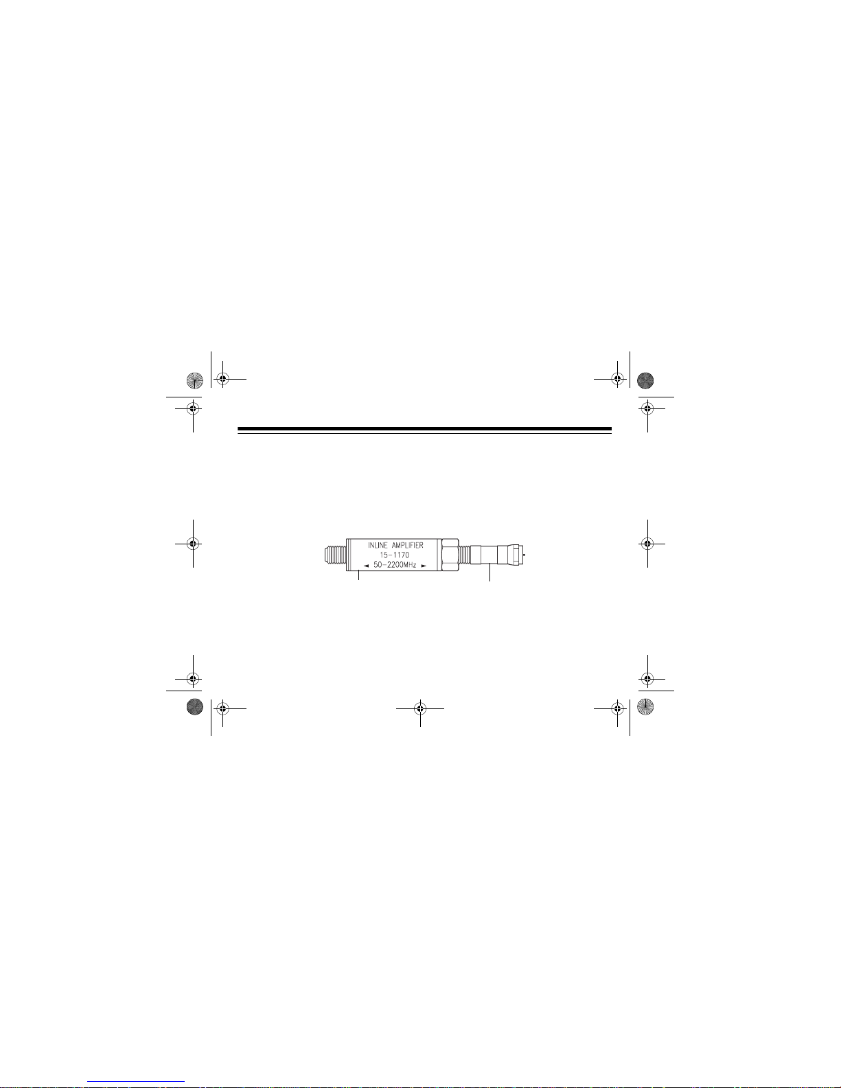
Amplifier
DC Block
15-1170.fm Page 5 Tuesday, July 13, 1999 4:35 PM

6
ONE ANTENNA/ONE RECEIVER SYSTEM
If you are using a single antenna with a single receiver, “Installation A” shows the proper connections.
Caution:
To avoid damage to your receiver and/or the amplifier power injector, carefully check
all the points listed below.
• Do not separate the amplifier from the DC block. The DC block must be between the
amplifier and the 300-to-75 ohm transformer at the antenna.
• Remove the DC block and the plastic tube that connects the DC block and the amplifier
when using with a satellite or powered antenna.
• Follow the connection labeling on the amplifier/DC block unit:
TO ANT, TO POWER INJEC-
TOR
. The amplifier will not receive power if they are reversed.
• Follow the con n ec ti o n l abe l in g o n t he po w e r in j ec t or:
TO TV, TO AMPLIFIER
. Your TV/radio
receiver will be damaged if they are reversed.
Note:
The In-Line Signal Amplifier is d esign ed for us e with F- typ e connec tors. For some a ntenna systems (such as scanners , for exa mple), you will have to use co nnecti on adapters or m ake
a special cable.
15-1170.fm Page 6 Tuesday, July 13, 1999 4:35 PM

7
Installation A
Caution:
To avoid damage to the amplifier, power injector or other connected equipment, do
not plug in the power injector until all connections have been double-checked.
Note:
An antenna transformer might no t be in cluded with your antenna and mi ght not be need-
ed. Check your antenna’s owner’s manual.
Antenna
Amplifier
DC Block
Antenna
TV/FM/Scanner
AC Outlet
Power Injector
Signal Output to
TV/FM/Receiver/Scanner
Transformer
15-1170.fm Page 7 Tuesday, July 13, 1999 4:35 PM

8
ONE ANTENNA/TWO RECEIVER SYSTEMS
If you are using a single antenna with two TV/radio receivers, “Installation B” shows the proper
connections. To avoid damage to your satellite/TV/radio receivers and/or the amplifier power
injector, caref ully check all the points listed below.
Note:
Make sure the power injector is between the amplifier and the splitter (before the signal
is split).
Installation B
Optional 2nd Amplifier
Amplifier
Transformer
Remove
DC Block
DC Block
TV
AC Outlet
75 ohm Splitter
Power Injector
To 2nd TV/Radio Receiver
Antenna
15-1170.fm Page 8 Tuesday, July 13, 1999 4:35 PM

9
ONE SATELLITE DISH/RECEIVER SYSTEM
Your In-Line Signal Amplifier ca n be us ed i n a one -w ire s ol uti on th at a ll ows y ou to com bin e th e
direct-to-home signal from your s atell ite dis h and th e VHF/UHF signa l from y our TV an tenna b y
using a satellite signal splitter/combiner (not supplied) or a TV/satellite diplexer (not supplied).
See the connection in “Installation C.”
Combining the Outdoor Signal
Use a satellite signal splitter/combiner to combine the output of the In-Line Signal Amplifier’s
signal and the direct-to-home satellite signal in a single coaxial output lead. The satellite/receiver transfers power to the In-Line Signal Amplifier and the satellite dish’s LNB (Low Noise
Block) unit. See the connection in “Installation C.”
Splitting the Indoor Signal
Use a TV/satellite diplexer to separate the In-Line Signal Amplifier antenna signal and the direct-to-home signal, then route them to the TV’s antenna input and the direct-to-home receiver’s input. See the connection in “Installation C.”
15-1170.fm Page 9 Tuesday, July 13, 1999 4:35 PM

10
Note
: Normally, the direct-to-home receiver supplies power to both the antenna amplifier and
the LNB converter.
Installation C
SAT
Dish
DC Passed
To LNB
In-Line
To ANT
Satellite Signal
Splitter Combiner
AMP
Section, 50-2200 MHz
DC 13V/17V From
Sat-Receiver
(15-1170)
ANT
SAT
TV SET
TO TV
ANT
LNB
IN
TV/Sat Diplexer
Amplifier
15-1170.fm Page 10 Tuesday, July 13, 1999 4:35 PM

11
AMPLIFIED ANTENNAS
You can use the In-Line Signal Amplifier with amplif ied antenna systems, as s hown in “Installation D.”
If the power supply provi ded with yo ur amplified antenna provid es a c en ter-p osi tiv e p ow er su pply, it can be used to pow er the In-L ine Sig nal Amp li fier as well; you do not need th e am pl ifi er’ s
power injector .
Caution:
The In-Line Signal Amplifier cannot be used if the amplified antenna power supply is
center negative.
In this case only, you should remove the DC block from the amplifier and connect the amplifier
directly to the F-type connector on the antenna. Remove the plastic tube that holds the amplifier and DC block together and unscrew the two pieces.
If the antenna is used with more than one TV receiver, you must follow all connection procedures for “One Antenna/Two Receiver Systems” on Page 8, except that the DC block between
the antenna and the amplifier will be removed, as described above.
Note:
The In-Line Signal Amplifier is d esigned for use w ith F- type c onnectors . For som e ante nna systems (such as scanners , for exa mple), you will have to use co nnecti on adapters or m ake
a special cable.
15-1170.fm Page 11 Tuesday, July 13, 1999 4:35 PM

12
Installation D
Antenna Power Supply
TV
Remove DC Block
Amplifier
Amplified Antenna
(Center Positive)
15-1170.fm Page 12 Tuesday, July 13, 1999 4:35 PM

13
Additional Amplification
If additional amplification is needed, you can connect another amplifier in the line with the first
amplifier. Remove the DC block from the optional second amplifier.
Notes:
• The In-Line Signal Amplifier can only be purchased as a kit, with the Power Injector and
DC Block. If you want to use a secon d amplifie r in your sy stem, ret ain the ext ra parts fo r
future additions to your system or as replacements if other parts are damaged or lost.
• If you connect another amplifier in the line with the first amplifier, make sure there is at
least 100 feet between each In-Line Signal Amplifier.
15-1170.fm Page 13 Tuesday, July 13, 1999 4:35 PM

14
PROBLEM SOLVING
If the satellite/TV/radio receiver does not operate correctly after you install the In-Line Signal Amplifier:
• Immediately unplug the power injector.
• Check all connections and compare them with the appropriate installation drawing(s) in
this manual.
If no problems are foun d in t he co nnec tio ns:
Plug in the power injector and try the satel lit e/TV/radio receiver again. If possible, try a different satellite/TV/radio receiver with the system or try
the satellite/TV/radio receiver with a different antenna system.
If the above procedures do not resolve the problem:
Take the unit to your local RadioShack store
for assistance.
15-1170.fm Page 14 Tuesday, July 13, 1999 4:35 PM

15
SPECIFICATIONS
Amplifier
Frequency ........................................................................................................... 50–2,220 MHz
Gain .............................................................................................. 50–2,200 MHz @10 dB MIN
Input Capability ................................................................... 83dB
µ
V MIN
(7 CHANNEL INPUTS)
Maximum Input for –60dB Third Order Distortion .......................... 84 dB µV MIN (Tested VHF)
73 dB µV MIN (Tested UHF)
Noise Figure ................................................................................ 50–900 MHz. @ 7.5 dB MAX
900–2200 MHz @ 9.8 dB MAX
Power Injector
Input ................................................................................................................... 120V AC 60Hz
Output Voltage .......................................................................................................... DC 12±1 V
Maximum Output ........................................................................................................... 200 mA
Insertion Loss ................................................................................ 50–950 MHz @1.5 dB MAX
951–1,750 MHz @ 2.5 dB MAX
1,751–2,200 MHz @ 4 dB MAX
15-1170.fm Page 15 Tuesday, July 13, 1999 4:35 PM

07A99 Printed in China
Limited Ninety-Day Warranty
This product is warranted by RadioShack against manufacturing defects in material and workmanship under normal
use for ninety (90) days from the date o f purchase from Ra dioShack company-ow ned stores and au thorized RadioShack franchisees and dealers. EXCEPT AS PROVIDED HEREIN, RadioShack MAKES NO EXPRESS WARRANTIES AND ANY IMPLIED WARRANTIES, INCLUDING THOSE OF MERCHANTABILITY AND FITNESS FOR
A PARTICULAR PURPOSE, ARE LIMITED IN DURATION TO THE DURATION OF THE WRITTEN LIMITED
WARRANTIES CONTAINED HEREIN. EXCEPT AS PROVIDED HEREIN, RadioShack SHALL HAVE NO LIABILITY OR RESPONSIBILITY TO CUSTOMER OR ANY OTHER PERSON OR ENTITY WITH RESPECT TO ANY LIABILITY, LOSS OR DAMAGE CAUSED DIRECTLY OR INDIRECTLY BY USE OR PERFORMANCE OF THE
PRODUCT OR ARISING OUT OF ANY BREACH OF THIS WARRANTY, INCLUDING, BUT NOT LIMITED TO,
ANY DAMAGES RESULTING FROM INCONVENIENCE, LOSS OF TIME, DATA, PROPERTY, REVENUE, OR
PROFIT OR ANY INDIRECT, SPECIAL, INCIDENTAL, OR CONSEQUENTIAL DAMAGES, EVEN IF RadioShack
HAS BEEN ADVISED OF THE POSSIBILITY OF SUCH DAMAGES.
Some states do not allow the limitations on how long an implied warranty lasts or the exclusion of incide ntal or consequential damages, so the above limitations or exclusions may not apply to you.
In the event of a product defect during the warranty p eriod, take the product and the RadioSha ck sales receipt as
proof of purchase date to any RadioShack store. RadioShack will, at its option, unless otherwise provided by law:
(a) correct the defect by pro duct repair without charge for parts an d labor; (b) replace the produ ct with one of the
same or similar design; or (c) refund th e purcha se pric e. All rep laced par ts and pro ducts, an d produ cts on whi ch a
refund is made, become th e p ro per ty o f R a dioS ha ck. New o r reco ndi tio ne d p art s an d p ro ducts may be used in the
performance of warranty service. Repair ed or re placed parts and products are warr anted fo r the remainde r of the
original warranty period. You will be charged for repair or replacement of the product made after the expiration of
the warranty period.
This warranty does not cover : (a ) d am ag e o r fa il ure cau sed by or attr i but able to acts of God, abuse, accident, misuse, improper or abnor mal usage, failure to fol low instructions, improper installation or maintenan ce, alteration,
lightning or other incidence of excess voltage or current; (b) any repairs other than those provided by a RadioShack
Authorized Service Facility; (c) consumables such as fuses or batteries; (d) cosmetic damage; (e) transportation,
shipping or insurance costs; or (f) costs of product removal, installation, set-up service adjustment or reinstallation.
This warranty gives you specific legal rights, and you may also have other rights which vary from state to state.
RadioShack Customer Relations, 200 Taylor Street, 6th Floor, Fort Worth, TX 76102
We Service What We Sell
04/99
15-1170.fm Page 16 Tuesday, July 13, 1999 4:35 PM
 Loading...