

Page 1

PRO-96PRO-96
Digital Trunking Handheld ScannerDigital Trunking Handheld Scanner
Catalog Number: 20-526Catalog Number: 20-526
20-526
CONTENTSCONTENTS
PagePage
SpecificationsSpecifications ........................................................................................................................................................................................................................................................................................................ 22
Block DiagramBlock Diagram ...................................................................................................................................................................................................................................................................................................... 44
Alignment and AdjustmentAlignment and Adjustment ................................................................................................................................................................................................................................................................ 55
TroubleshootingTroubleshooting .................................................................................................................................................................................................................................................................................................. 99
Printed Circuit BoardPrinted Circuit Board .............................................................................................................................................................................................................................................................................. 1616
Wiring DiagramWiring Diagram ................................................................................................................................................................................................................................................................................................ 2020
Exploded ViewExploded View ..................................................................................................................................................................................................................................................................................................2121
Mechanical Parts ListMechanical Parts List .............................................................................................................................................................................................................................................................................. 2222
Electrical Parts ListElectrical Parts List ...................................................................................................................................................................................................................................................................................... 2323
Semiconductor Lead IdentificationSemiconductor Lead Identification .................................................................................................................................................................................................................................... 5757
Microprocessor (IC204) Port FormatMicroprocessor (IC204) Port Format .............................................................................................................................................................................................................................. 6363
Schematic DiagramSchematic Diagram .................................................................................................................................................................................................................................................................................. 6464
© 2003 RadioShack Corporation© 2003 RadioShack Corporation
All Rights Reserved.All Rights Reserved.
Page 2

SPECIFICATIONSSPECIFICATIONS
Frequency CoverageFrequency Coverage 25.000-27.995 MHz25.000-27.995 MHz 5 kHz steps (AM)5 kHz steps (AM)
28.000-54.000 MHz28.000-54.000 MHz 5 kHz steps (FM)5 kHz steps (FM)
108.000-136.9875 MHz108.000-136.9875 MHz 12.5 kHz steps (AM)12.5 kHz steps (AM)
137.000-150.775 MHz137.000-150.775 MHz 5 kHz steps (FM)5 kHz steps (FM)
150.7825-150.8125 MHz150.7825-150.8125 MHz 7.5 kHz steps (FM)7.5 kHz steps (FM)
150.815-154.4525 MHz150.815-154.4525 MHz 7.5 kHz steps (FM)7.5 kHz steps (FM)
154.45625-154.47875 MHz154.45625-154.47875 MHz 7.5 kHz steps (FM)7.5 kHz steps (FM)
154.4825-154.505 MHz154.4825-154.505 MHz 7.5 kHz steps (FM)7.5 kHz steps (FM)
154.510-154.525 MHz154.510-154.525 MHz 5 kHz steps (FM)5 kHz steps (FM)
154.5275-154.54625 MHz154.5275-154.54625 MHz 6.25 kHz steps (FM)6.25 kHz steps (FM)
154.5475-154.6075 MHz154.5475-154.6075 MHz 7.5 kHz steps (FM)7.5 kHz steps (FM)
154.610-154.655 MHz154.610-154.655 MHz 5 kHz steps (FM)5 kHz steps (FM)
154.6575-156.2475 MHz154.6575-156.2475 MHz 7.5 kHz steps (FM)7.5 kHz steps (FM)
156.250-157.475 MHz156.250-157.475 MHz 5 kHz steps (FM)5 kHz steps (FM)
157.4775-161.565 MHz157.4775-161.565 MHz 7.5 kHz steps (FM)7.5 kHz steps (FM)
161.570-173.200 MHz161.570-173.200 MHz 5 kHz steps (FM)5 kHz steps (FM)
173.20375-173.2225 MHz173.20375-173.2225 MHz 6.25 kHz steps (FM)6.25 kHz steps (FM)
173.225-173.3875 MHz173.225-173.3875 MHz 6.25 kHz steps (FM)6.25 kHz steps (FM)
173.390-173.415 MHz173.390-173.415 MHz 6.25 kHz steps (FM)6.25 kHz steps (FM)
173.420-174.000 MHz173.420-174.000 MHz 5 kHz steps (FM)5 kHz steps (FM)
216.0025-221.9975 MHz216.0025-221.9975 MHz 5 kHz steps (FM)5 kHz steps (FM)
222.000-225.000 MHz222.000-225.000 MHz 5 kHz steps (FM)5 kHz steps (FM)
406.000-512.000 MHz406.000-512.000 MHz 6.25 kHz steps (FM)6.25 kHz steps (FM)
806.000-823.9875 MHz806.000-823.9875 MHz 6.25 kHz steps (FM)6.25 kHz steps (FM)
849.000-868.9875 MHz849.000-868.9875 MHz 6.25 kHz steps (FM)6.25 kHz steps (FM)
894.000-960.000 MHz894.000-960.000 MHz 6.25 kHz steps (FM)6.25 kHz steps (FM)
1240.000-1300.000 MHz1240.000-1300.000 MHz 6.25 kHz steps (FM)6.25 kHz steps (FM)
UnitUnit NiminalNiminal LimitLimit
SensitivitySensitivity
FM: (S+N)/N=20 dBFM: (S+N)/N=20 dB 25-54 MHz25-54 MHz µµVV 0.10.1 11
Dev.: 3 kHz at 1 kHzDev.: 3 kHz at 1 kHz 108-136.9875 MHz108-136.9875 MHz µµVV 0.30.3 11
137-225 MHz137-225 MHz µµVV 0.50.5 22
406-512 MHz406-512 MHz µµVV 0.50.5 22
806-960 MHz806-960 MHz µµVV 0.70.7 33
1240-1300 MHz1240-1300 MHz µµVV 0.70.7 44
AM: (S+N)/N=20 dBAM: (S+N)/N=20 dB 25-54 MHz25-54 MHz µµVV 11 33
Mod.: 60% at 1 kHzMod.: 60% at 1 kHz 108-136.9875 MHz108-136.9875 MHz µµVV 11 33
137-225 MHz137-225 MHz µµVV 1.51.5 55
406-512 MHz406-512 MHz µµVV 22 66
806-960 MHz806-960 MHz µµVV 22 66
1240-1300 MHz1240-1300 MHz µµVV 33 1212
22
Page 3

UnitUnit NiminalNiminal LimitLimit
Data decode sensitivityData decode sensitivity
CT CT 350 Hz Dev. at 41, 174, 450, 860 MHz350 Hz Dev. at 41, 174, 450, 860 MHz µµVV 11 33
DC DC 350 Hz Dev. at 41, 174, 450, 860 MHz350 Hz Dev. at 41, 174, 450, 860 MHz µµVV 11 33
ED ED 4 kHz Dev. at 174, 450, 860 MHz4 kHz Dev. at 174, 450, 860 MHz µµVV 11 44
MO (Voice Channel) MO (Voice Channel) 350 Hz Dev. at 174, 450, 860 MHz350 Hz Dev. at 174, 450, 860 MHz µµVV 0.50.5 33
MO (Control Channel) MO (Control Channel) 4 kHz Dev. at 174, 450, 860 MHz4 kHz Dev. at 174, 450, 860 MHz µµVV 11 44
WX Alert 1050 Hz tone WX Alert 1050 Hz tone 3 kHz Dev. at 162.4 MHz3 kHz Dev. at 162.4 MHz µµVV 0.30.3 11
WX Digital Weather Alert WX Digital Weather Alert 4 kHz Dev. at 162.4 MHz4 kHz Dev. at 162.4 MHz µµVV 0.50.5 22
Squelch sensitivitySquelch sensitivity
at threshold at threshold (AM/FM)(AM/FM) µµVV 0.50.5 22
at tight (FM) at tight (FM) dBdB 2525 1515
at tight (AM) at tight (AM) dBdB 2020 1010
Spurious refection (Except Primary image)Spurious refection (Except Primary image) at 174 MHzat 174 MHz dBdB 4040 3030
Acceptable radio frequency displacement (EIA RS-204D)Acceptable radio frequency displacement (EIA RS-204D) kHzkHz ±6±6 ±3±3
Signal to noise ratio (FM and AM)Signal to noise ratio (FM and AM)
RF input: 100 RF input: 100 µµVV 25-54 MHz25-54 MHz dBdB 4040 3030
Dev. 3 kHz at 1 kHz Dev. 3 kHz at 1 kHz 108-136.9875 MHz108-136.9875 MHz dBdB 4040 3030
Mod.: 60% at 1 kHz Mod.: 60% at 1 kHz 137-225 MHz137-225 MHz dBdB 4040 3030
406-512 MHz406-512 MHz dBdB 3535 2525
806-960 MHz806-960 MHz dBdB 3535 2525
1240-1300 MHz1240-1300 MHz dBdB 3535 2525
Residual noiseResidual noise Volume control, set to its minimum, squelchedVolume control, set to its minimum, squelched mVmV 11 33
Scanning rateScanning rate without trunkingwithout trunking channels/sec.channels/sec. 6060 33-6633-66
Search rateSearch rate at 162.25-164.25 MHzat 162.25-164.25 MHz steps/sec.steps/sec. 7575 60-8560-85
Scan delay timeScan delay time sec.sec. 22 1-31-3
Audio output powerAudio output power 10% THD10% THD mWmW 170170 140140
Current drain (using AC or DC adapter)Current drain (using AC or DC adapter) SquelchedSquelched mAmA 130130 150150
Channels of operationChannels of operation Any 500 channels in any band combination and 11 in V-ScannerAny 500 channels in any band combination and 11 in V-Scanner
Channels, frequency,Channels, frequency, Liquid crystal displayLiquid crystal display
and mode display and mode display
Receiving systemReceiving system Direct key entry digital-controlled synthesizer,Direct key entry digital-controlled synthesizer,
1st IF: 380.72750-380.86875 MHz1st IF: 380.72750-380.86875 MHz
2nd IF: 21.4 MHz2nd IF: 21.4 MHz
3rd IF: 455 kHz3rd IF: 455 kHz
Power sourcePower source 6V DC negative ground only6V DC negative ground only
4AA batteries or a suitable adapter4AA batteries or a suitable adapter
JacksJacks Antenna, earphone, PC/IF, and external powerAntenna, earphone, PC/IF, and external power
Dimensions (HWD)Dimensions (HWD) 6 3/16 x 2 7/16 x 1 3/4 inches (157 x 62 x 41 mm)6 3/16 x 2 7/16 x 1 3/4 inches (157 x 62 x 41 mm)
WeightWeight apporox. 8.8 oz. (250 g) without antenna and batteriesapporox. 8.8 oz. (250 g) without antenna and batteries
Note:Note: Nominal specs represent the design specs. All units should be able to approximate these specifications. Nominal specs represent the design specs. All units should be able to approximate these specifications.
Some units will exceed while some many drop below these specs. Limit specs represent the absolute worst condi-Some units will exceed while some many drop below these specs. Limit specs represent the absolute worst condi-
tion still considered acceptable. A unit should NEVER fail to meet limit specs.tion still considered acceptable. A unit should NEVER fail to meet limit specs.
33
Page 4
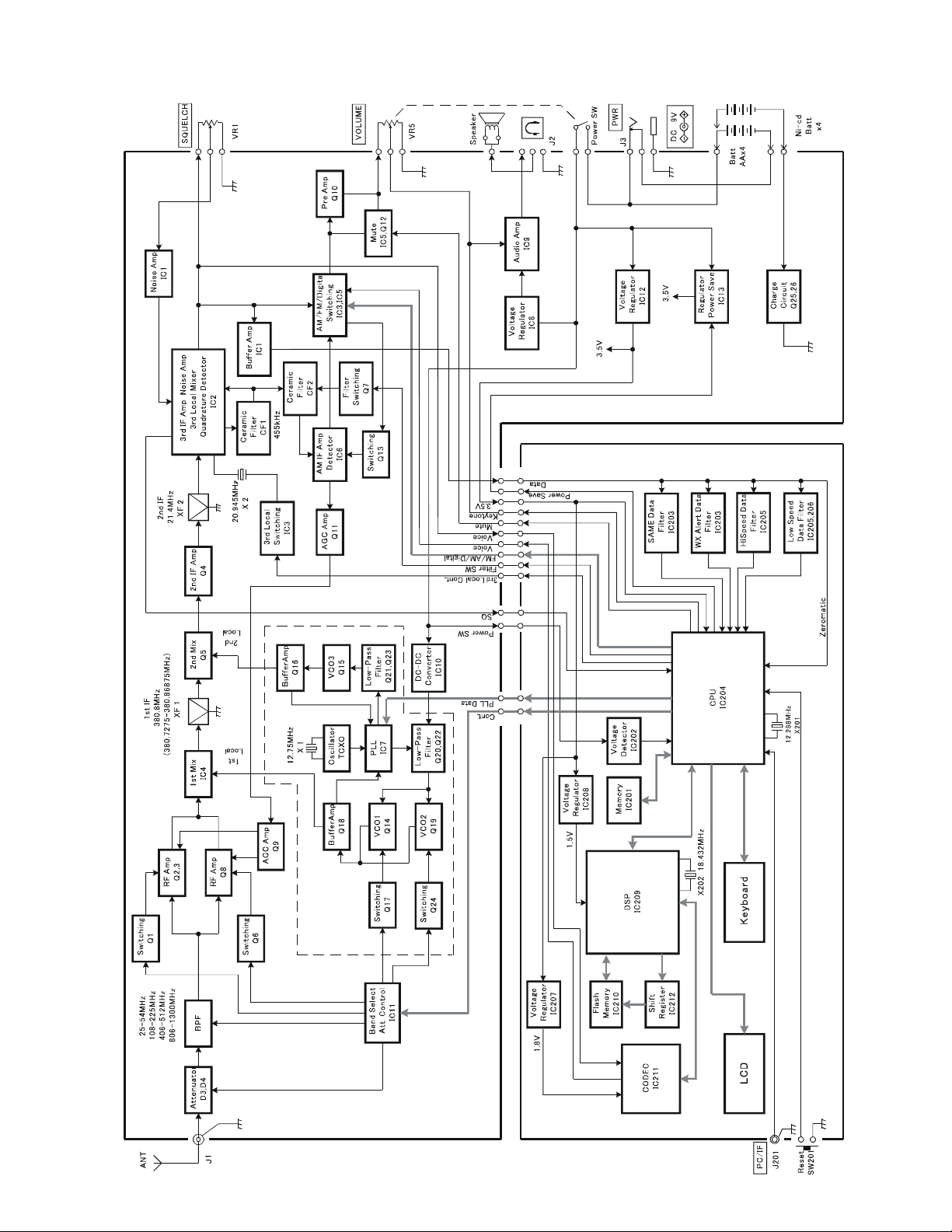
BLOCK DIAGRAMBLOCK DIAGRAM
44
Page 5

ALIGNMENT AND ADJUSTMENTALIGNMENT AND ADJUSTMENT
TP2
TP1
GND
TP5
TP4
TP3
L27
L22
L23
VR4
VR3
VR2
ALIGNMENT AND TEST POINTSALIGNMENT AND TEST POINTS
ALIGNMENT PREPARATIONALIGNMENT PREPARATION
Test Equipment RequiredTest Equipment Required
ll OscilloscopeOscilloscope
ll DC SSVMDC SSVM
ll AM/FM signal generator (25 to 1300 MHz)AM/FM signal generator (25 to 1300 MHz)
ll Frequency counter (800 MHz)Frequency counter (800 MHz)
L2
T1
T2
Notes:Notes:
ll Use non-metallic tuning toolsUse non-metallic tuning tools
ll The test equipment and receiver should be warmed up for at least 10 minutes before proceeding with alignment.The test equipment and receiver should be warmed up for at least 10 minutes before proceeding with alignment.
ll The signal level from the generator should be kept as low as possible to obtain a usable output.The signal level from the generator should be kept as low as possible to obtain a usable output.
ll The memory backup circuit can hold the programmed channel memories for about one hour.The memory backup circuit can hold the programmed channel memories for about one hour.
Program Channels 000 through 011 as follows:Program Channels 000 through 011 as follows:
Channel Frequency and Band Mode Channel Frequency and Band Mode
000 960.000 MHz (FM) 006 173.390 MHz (FM)
001 25.000 MHz (FM) 007 173.420 MHz (FM)
002 1300.000 MHz (FM) 008 154.5475 MHz (FM)
003 216.0025 MHz (FM) 009 124.000 MHz (AM)
004 512.000 MHz (FM) 010 154.610 MHz (FM)
005 174.000 MHz (FM) 011 406.000 MHz (FM)
55
Page 6

ALIGNMENT PROCEDURESALIGNMENT PROCEDURES
DC SSVM
DC SSVM
PLL2 VCO AlignmentPLL2 VCO Alignment
Control Setting Test Instrument Connection Adjust Result
OFF/VOLUME control: ON.
SQUELCH control: Fully
counterclockwise (CCW).
Select channel 004.
PLL1 VCO1 AlignmentPLL1 VCO1 Alignment
Control Setting Test Instrument Connection Adjust Result
OFF/VOLUME control: ON.
SQUELCH control: CCW.
Select channels 000 and 001.
PLL1 VCO2 AlignmentPLL1 VCO2 Alignment
Control Setting Test Instrument Connection Adjust Result
OFF/VOLUME control: ON.
SQUELCH control: CCW.
Select channels 002 and 003.
Connect DC SSVM to TP3.
See Figure 1.
Connect DC SSVM to TP2.
See Figure 2.
Connect DC SSVM to TP2.
See Figure 2.
L23 Adjust L23 to 2.0 volts on the DC
SSVM. See Table 2 and 3.
L22 1. Select channel 000 and adjust
L22 to 18.0 volts on the DC
SSVM. See Table 3.
2. Select channel 001 and be
sure the DC SSVM reads 2.0-5.0
volts. (No adjustments are
necessary for the coil.) See Table
2.
L27 1. Select channel 002 and adjust
L27 to 20.0 volts on the DC
SSVM. See Table 3.
Channel Frequency Voltage
000 960.000 MHz 17.0-19.0 volts at TP2
001 25.000 MHz 2.0-5.0 volts at TP2
002 1300.000 MHz 19.0-21.0 volts at TP2
003 216.0025 MHz 1.0-4.0 volts at TP2
004 512.000 MHz 1.8-2.2 volts at TP3
TP3Unit
Under Test
2. Select channel 003 and be
sure the DC SSVM reads 1.0-4.0
volts. (No adjustments are
necessary for the coil.) See Table
2.
Table 2Table 2
TP2Unit
Under Test
Figure 1 Figure 2Figure 1 Figure 2
66
Page 7

Adjustment of Coils L22, L23, and L27Adjustment of Coils L22, L23, and L27
Use
non-metallic
PCB
FM Signal
Generator
ANT. Jack
DC SSVM
Oscilloscope
Coil
Notes:Notes:
ll Be very careful when doing coil pitch adjustmentBe very careful when doing coil pitch adjustment
because it greatly affects the frequency.because it greatly affects the frequency.
ll Secure the coil with glue after alignment. Be sure theSecure the coil with glue after alignment. Be sure the
glue is dry and the coil is secured. Also, be sure thatglue is dry and the coil is secured. Also, be sure that
the environmental temperature is normal. Then, re-the environmental temperature is normal. Then, re-
peat VCO (PLL2 and PLL1) alignments on Page 6.peat VCO (PLL2 and PLL1) alignments on Page 6.
tuning tool
Figure 3Figure 3
Table 3Table 3
455 kHz FM Discriminator Coil Alignment455 kHz FM Discriminator Coil Alignment
Control Setting Test Instrument Connection Adjust Result
Each coil should be adjusted carefully by chang-Each coil should be adjusted carefully by chang-
ing the pitch of the coil little by little using a non-ing the pitch of the coil little by little using a non-
metallic tuning tool as shown in Figure 3.metallic tuning tool as shown in Figure 3.
Increase the pitch of the coil when the measuredIncrease the pitch of the coil when the measured
voltage at TP2 or TP3 is higher than the voltagevoltage at TP2 or TP3 is higher than the voltage
listed in Table 2 for the PLL2 VCO alignment, PLL1listed in Table 2 for the PLL2 VCO alignment, PLL1
VCO1 alignment, and PLL1 VCO2 alignment.VCO1 alignment, and PLL1 VCO2 alignment.
Decrease the pitch of the coil when the measuredDecrease the pitch of the coil when the measured
voltage at TP2 or TP3 is lower than the voltagevoltage at TP2 or TP3 is lower than the voltage
listed in Table 2 for the PLL2 VCO alignment, PLL1listed in Table 2 for the PLL2 VCO alignment, PLL1
VCO1 alignment, and PLL1 VCO2 alignment.VCO1 alignment, and PLL1 VCO2 alignment.
OFF/VOLUME control: ON.
SQUELCH control: CCW.
Select channel 010.
Connect the signal generator
to the ANT jack and the DC
SSVM to TP4. See Figure 4.
1st IF (380.8 MHz) Coil Alignment1st IF (380.8 MHz) Coil Alignment
Control Setting Test Instrument Connection Adjust Result
OFF/VOLUME control: ON.
SQUELCH control: CCW.
Select channel 009.
Connect the signal generator
to the ANT jack and the
oscilloscope and an 8-ohm
dummy load to the
headphone jack. See Figure
5.
Unit
Under Test
Figure 4Figure 4
T2 Set the signal generator
freuqency to 154.610 MHz, 100
uV output (no modulation) and
adjust T2 for 1.3 +/- 0.05 volts on
the DC SSVM.
TP4
T1 1. Set the signal generator
freuqency to 124 MHz, AM: 60%
modulation at 1 kHz and RF
output under 1 uV.
2. Adjust T1 for maximum
sensitivity.
AM Signal
Generator
ANT. Jack
Headphone
Unit
Under Test
Figure 5Figure 5
77
Jack
8ohm
Page 8

3rd Local Alignment3rd Local Alignment
FM Signal Generator
Oscilloscope
Note:Note: You must adjust Reference Frequency Osc. Alignment before you adjust this procedure. You must adjust Reference Frequency Osc. Alignment before you adjust this procedure.
Control Setting Test Instrument Connection Adjust Result
OFF/VOLUME control: ON.
SQUELCH control: CCW.
Select channels 006, 007 and
008.
Connect the signal generator
to the ANT jack and frequency
counter to TP5. See Figure 6.
ANT
Unit
Under Test
TP5
Figure 6Figure 6
VR2
VR3
VR4
1. Set the signal generator
freuqency to 173.390 MHz (No
modulation). Select channel 006
and adjust VR4 so the frequency
is 455 kHz +/- 10 Hz.
2. Set the signal generator
freqeuency to 173.420 MHz ( No
modulation). Select channel 007
and adjust VR2 so the frequency
is 455 kHz +/- 10 Hz.
3. Set the signal generator
frequency to 154.5475 MHz (No
modulation). Select channel 008
and adjust VR3 so the frequency
is 455 kHz +/- 10 Hz.
Frequency Counter
IF (380.8 MHz) Trap AdjustmentIF (380.8 MHz) Trap Adjustment
Control Setting Test Instrument Connection Adjust Result
OFF/VOLUME control: ON.
SQUELCH control: CCW.
Select channel 011.
FM Signal
Generator
Connect the signal generator
to the ANT jack and
oscilloscope to headphone
jack across 8-ohm dummy
load. See Figure 7..
ANT. Jack
Headphone
Unit
Under Test
Figure 7Figure 7
L2 1. Set the signal generator
frequency to 380.750 MHz, FM: 3
kHz deviation at 1 kHz.
2. Adjust L2 to decrease the
sensitivity.
3. Set the signal generator
frequency to 406.000 MHz, FM: 3
kHz deviation at 1 kHz and check
that the scanner receives the
signal.
8-
Jack
ohm
88
Page 9
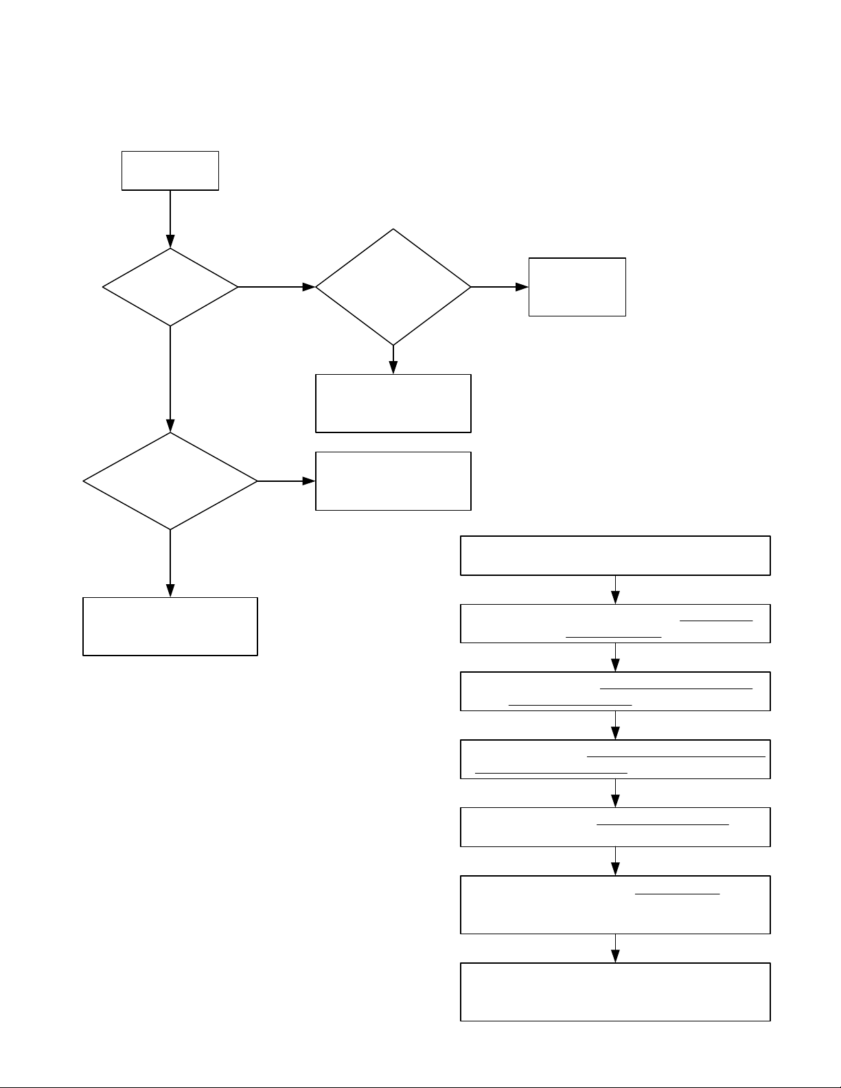
Reception CheckReception Check
Power ON
TROUBLESHOOTINGTROUBLESHOOTING
Is the display
normal?
YES
Is the voltage
of TP2 about 18 V at
960 MHz?
YES
Microprocessor is OK.
NO NO
NO
Is EEPROM check
program OK?
YES
Defective IC204 and/or
associated circuit.
Defective IC7 and/or
associated circuit.
Press 0 while the scanner shows Welcome to
Defective
IC201.
EEPROM check programEEPROM check program
procedure as follows:procedure as follows:
Power on the scanner.
Digital Trunking.
Note:Note: This procedure (EEPROM check program) This procedure (EEPROM check program)
clears all information you stored in the scanner’sclears all information you stored in the scanner’s
working memory.working memory.
99
The scanner shows System Tests Select Test
Exits if no Key Press. Then press 5.
The scanner shows EEPROM Test Erase Memory
ENTER if YES CL to EXIT. Then press ENTER.
The scanner shows EEPROM TEST Mode and
automatically starts the EEPROM test program.
When the scanner shows EEPROM OK! , this
scanner's EEPROM have no problem. Turn off the
scanner.
Turn on the scanner, then the scanner initialize
the working memory.
Page 10

Microprocessor CheckMicroprocessor Check
Power ON.
NO
Defective key contact.
Does the display
work properly?
YES
Does the key entry
work properly?
YES
IC204 is OK.
NO
Does 3.5 volts exist at
IC204 pin 30?
YES
NO
Defective IC12.
Is the clock
oscillation normal at pin
22 of IC204?
YES
Defective IC204.
1010
NO
Defective X201 and/
or associated
circuits of IC204.
Page 11

Audio SectionAudio Section
No audio
Is
there any audio at pin 2
of IC9?
YES
Does
5 V exist at IC9
pin 7?
YES
Defective IC9 and/or
associated circuit.
NO
Defective IC2.
NO
Defective IC8 and/or R107.
1111
 Loading...