

Page 1

Owner’s Manual
Cat. No. 20-521
PRO-91 150-Channel
Handheld Trunking Scanner
Please read before using this equipment.
Page 2

FEATURES
Your RadioShack PRO-91 150-Channel Handheld
Trunking Scanner is one of a new generation of scanners designed to track Motorola Type I and Type II
(such as Smartnet and Privacy Plus) and hybrid analog trunking systems, which are extensively used in
many 800 MHz communication systems.
Trunking communications systems let a large group of
2-way radio users (or even different groups of 2-way radio users) efficiently use a large range of frequencies.
Instead of selecting a specific frequency for a transmission, the user si m ply select s a talk gr ou p. The t run ki ng
system automatically transmits the call on the first available frequency, and also sends (on a different frequency called a data channel) a code that uniquely identifies
that transmission.
Since t he trun king system might sen d a call an d its re sponse on dif ferent frequenc i es, it is dif ficult to liste n t o
trunk ed communic ations using a r egular scan ner. The
PRO-9 1 lets you select and monitor the data chan nel
frequen cy sent with a 2-w ay radio transm issi o n, so you
can he ar the ca ll and res ponse for th at u ser a nd m ore
easily “follow” the conversation.
The scanner also lets you scan conventional transmissions, and is preprogrammed with service banks for
convenience. By pressing a single button, you can
quickly search those frequencies most commonly
used by public service and other agencies without tedious and compli cated programming.
This sc ann er gi ve s y o u di r ect ac ces s t o ove r 30 ,00 0 e xciting frequencies, including police and fire departments, ambulance services, and amateur radio
services, and you can change your selection at any
time.
Your scanner also has these special fe atures:
Triple-Conversion Circuitry
— virtually eliminates
any interference from IF (intermediate frequency) images, so you hear only the selected frequency.
RadioShack is a registered trademark used by Tandy Corporation.
Hypersearch and Hyperscan are trademarks used by
2
©
1998 Tandy Corporation.
All Rights Reserved.
Tandy Corporation.
Page 3

Five Channel-Storage Banks — you can store up to
30 channels in each of 5 different banks to group channels so you can more easily identify calls.
Five Scan Lists — you can store up to 50 trunking IDs
in each trunk tracking bank.
Two-Second Scan Delay — delays scanning for about
2 seconds before moving to another channel, so you
can hear more replie s that are made on the sam e channel.
Lock-Out Function — lets you set your scanner to sk ip
over specified channels or frequencies when scanning
or searching, and skip over IDs when tracking trunked
systems.
Priority Channels — lets you program one channel in
each bank (5 in all) and then have the scanner check
that channel every 2 seconds while it scans the bank,
so you don't miss transmissions on those channels.
Five Service Banks — frequen cies are preset in separate police (fire/emergency), aircraft, ham, marine, and
weather banks, to make it easy to locate specific types
of cal ls.
Hypersearch — lets you set the scanner to search at
up to 300 steps per second. The normal search speed
is 100 steps per second.
Hyperscan — the scanner automatically scans up to
50 channels per second in frequency bands with 5 kHz
steps, to help you quickly find interesting broadcasts.
Key Lock — lets you lock the scanner's keys to help
prevent accidental changes to the scanner's programming.
Data Signal Skip — lets you set the scanner to skip
non-modulated or data signals (such as fax or modem
transmissions) during searches. This lets the scanner
avoid non-voice signal s, m aking a search faster.
Manual Access — lets you directly access any channel.
Liquid-Crystal Display — makes it easy to view and
change programming informat ion.
Display Backlight — makes the scanner easy to read
in low-light situations .
3
Page 4

Flexible Antenna with BNC Connector — provides
excellent reception and is designed to help prevent antenna breakage. Or, you can connect an external antenna.
Mon i tor M emories — le t you tem p orar ily stor e up to 5
frequenci es or IDs.
Memory Backup — keeps the frequencies stored in
memory for an extended ti me if the PRO-91 los es power.
Three Power Options — let you power the scanner
using internal batteries, external AC power using an
optional AC adapter/charger, or DC power using an optional DC cigarette-lighter power cable.
Key Confirmation Tones — the scanner sounds a
tone when you perform an operation correctly, and an
error tone if you make an error.
Battery Save — saves battery power when the scanner does not detect any transmissions for more than 5
seconds when a channel is manually selected.
Battery Low Alert — warns you when battery power
gets low.
Your scanner can re ceive these bands:
Frequency
Range (MHz)
Step
(kHz)
Transmission
29–29.7 5 10-Meter Ham Band
29.7–50 5 VHF Lo
50–54 5 6-Meter Ham Band
108–136.9750 12.5 Aircraft
137–144 5 Military Land Mobile
144–148 5 2-Meter Ham Band
148–174 5 VHF Hi
406–420 12.5 Federal Government
420–450 12.5 70-cm Ham Band
450–470 12.5 UHF Standard Band
470–512 12.5 UHF “T” Band
806–956 12.5 Public Service
4
“800” Band, exce pt
cellular band
Page 5

We recommend you record your scanner’s serial number here. The number is on t he back panel.
Serial Number : ___________________________
FCC NOTICE
Your scanner might cause radio or TV interference
even when it is op erating prop erly. To det ermine whether your scanner is causing the interference, turn off
your scanner. If the interference goes away, your scanner is causing it. Try the following methods to eliminate
the interference:
• Move your scanner away from the receiver
• Connect your scanner to an outlet that is on a different electrical circuit from the recei ver
• Contact your local RadioShack st ore for help
Note:
a permit in some ar eas. Check the laws in your area.
Mobile use of this scanner is unl awful or requires
SCANNING LEGALLY
Your scanner covers frequencies used by many different groups inclu din g police and fire departmen ts, am bulance services, government agencies, private
companies, amateur radio services, military operat ions,
pager services, and wireline (telephone and telegraph)
service providers. It is legal to listen to almost every
transmission your scanner can receive. However, there
are some transmissions you should never intentionally
listen to. These i nclude:
• Telephone conversations (cellular, cordless, or
other private means of telephone signal transmission)
• Pager transm issions
• Any scrambled or encrypted transmissions
According to the Electronic Communications Privacy
Act (ECPA), you are subject to fines and possible imprisonment for intentionally listening t o, using, or divulging the contents of such a transmission unless you
have the consent of a party to the communication (unless such act ivity is otherwi se il legal).
This scanner is designed to prevent reception of illegal
transmissions, in compliance with the law which re-
5
Page 6

quires that scanners be manufactured in such a way as
to not be easily modifiable to pick up those transmissions. Do not open your scanner's case to make any
modifications that could allow it to pick up transmissions that it is not legal to listen to. Doing so could subject you to legal penalties.
We encourage responsible, legal scanner use.
CONTENTS
Preparation ............................................................ 10
Powe r S ou r ce s ........... ........ ....... ............ ........ ... 10
Using Internal Batteries ............................ 10
Charging Nickel-Cadmium Batter ies ......... 12
Using AC Power ....................................... 13
Using Vehicle Battery Power .................... 14
Connecting the Antenna ............... ................. .. 16
Connecting an Optional Antenna .............. 16
Connecting an Earphone/Headphones ............ 17
Listening Safely ........................................ 17
Traffic Safety ............................................. 17
Connecting an Extension Speaker ................... 18
Attaching the Belt Clip ...................................... 18
About Your Scanner .............................................. 19
A Look at the Keypad ..... .. ........ ................. ....... 20
A Look at the Display .......... ......... ........ .. ........ .. 21
Understandi ng Banks ................. .. ........ ........ .... 23
Service Banks ........................................... 23
Channel Stora ge Banks ................ .. ........ .. 23
Monitor Memories ..................................... 24
Operation ............................................................... 25
Turning On the Scanner/Set ting Squelch ..... .. .. 25
Storing Known Frequencies into Channels ...... 26
Searching For and Temporarily Storing
Active Frequenc ies ............................... ........ .... 27
Limit Search .............................................. 27
Direct Search ............................................ 28
Service Bank Search ................................ 29
Search Skip Memory ................................ 30
Listening to the Monitor Memories ................... 31
Moving a Frequency From a Monitor Memory
to a Channel ..................................................... 31
Scanning the Stored Channels ........................ 32
Manually Sel ecting a Channel ............. ........ .... 32
6
Page 7

Special Features .................................................... 34
Delay ................................................................ 34
Turning Channel-St orage Banks On and Off ... 34
Locking Out Channels .. .. ........ ......... ........ .. ....... 35
Priority .............................................................. 35
Using the Keylock ............................................ 37
Usin g the D is play Bac k light ....... ........ ............ ... 37
Changing Search Speeds ................................ 37
Turning the Key Tone Off/On ............................ 38
Turning the Battery Save Function Off /On ....... 38
Skipping Data Signals ...................................... 39
Trunk Tracking ....................................................... 40
Types of Trunki ng S ys te ms ....... ... ............ ....... . 40
Setting the Scanner to the
Trun k Tracking Mode .............. ...................... .... 41
Setting Squelch for the Trunk Tracking Mode . . 42
Storing Trunked Frequencies . .. ........ ......... ....... 42
Scanning a Trunked Bank ................................ 44
Monitoring an Active ID ............................. 45
Temporarily Storing an ID into the
Monitor ID Memory ................................... 45
Locking Out IDs ........................................ 46
Unlocking a Single ID ................................ 46
Unlockin g All ID s .............. ....... ........ .......... 46
Using Trunk Tracking Scan Delay ............. 47
Monitoring IDs ........................................... 47
Chann e l A ct ivity B a rs .... ... ............ ....... ........ ..... 48
Scan Li sts ... ....... ............ ........ ....... ............ ....... . 49
Manually Sto ring IDs into Scan Lists ...... .. 49
Moving IDs to Scan Lists .......................... 50
Deleting a Stor ed ID ....... ............ ....... ....... . 50
Scanning the Scan Lists ................................... 51
Scanning Type I and Hybrid Trunked
Systems ............................................................ 51
Selecting a Preset Fleet Map .................... 55
Programming a Fleet Map ........................ 56
Programming a Hybrid System ................. 57
A General Guide to Scanning ............................... 58
Guide to Frequen cies .................. .. ........ ......... .. 58
Guide to the Action Bands ............................... 59
Band A llo c a tio n .... .. .. ............. ....... ....... ............ . 60
National Weather Frequen cies ....... .. ......... 58
Canadian Weather Frequencies ............... 58
Birdie Frequencies ... .. ......... ........ .. ........ .... 58
Typi cal Band Usage .................................. 59
Primary Usage .............. ................. ......... .. 59
7
Page 8

Frequency Conversion 63
Troubl esh ooting 64
Resetting the Scanner ..................................... 67
Car e an d M a in t en a n c e ......... ... ............ ....... ........ ... 68
Spec ific atio ns .... ..... .. ..... ..... ..... .. ..... ..... .. ..... ..... ..... . 69
8
Page 9

PREPARATION
POWER SOURCES
You can power y our scanner f rom any of t hree sou rce s:
• Internal batteries (not supplied)
• Standard AC p ower (us ing an o ptiona l AC adapt er )
• Vehicle battery power (using an optional DC
adapter)
Using Internal Batteries
You can power your scanner using four AA batteries.
For the longest operation and best performance, we
recommend alkaline batteries (such as Cat. No. 23-
552).
You can also use four rechargeable nickel-cadmium
batteries ( Cat. No. 23-125). Before you use nickel-cadmium batteries, you must charge them (see “Charging
Nic k el-Cadm ium Batt er i e s” on Page 11) .
Follow these steps to install bat teries.
1. Turn
2. Slide up and hold the tab on the back of the scan-
VOLUME/OFF
to make sur e the power is turned off.
ner, then pull up the battery compartme nt cover.
counterclockwise until it clicks
9
Page 10

3. If you are installing alkaline batteries, use a
pointed object such as a pencil to set
JACK NI-CD
ALKALINE
. Or,if you are instal li ng nickel-cadmium
batteries, set it to
inside the compartment to
NI-CD
.
ALKALINE
Warning:
NI-CD
to
Never set
if you are installing non-rechargeable bat-
ALKALINE JACK NI-CD
teries. Non-rechargeable batteries can get hot or
explode if you try to recharge them.
4. Install two batteries in the compartment and two in
the cover as indicated by the polarity symbols (+
and –) marked insi de those locatio ns.
Cautions:
• Use only fresh batteries of the requi red size and
recommended type.
• Always remove old or weak batteries. Batteries
can leak chemicals that destroy electronic circuits.
• Do not mix old and new batteries, different
types of batteries (standard, alkaline, or
rechargeable), or rechargeable batteries of different capacities.
5. Replace t he cover.
10
Page 11

If
BATT.Lo
flashes and the scanner beeps every 15
seconds, replace (standard/alkaline) or recharge (rechargeable nickel-cadmium) the batteries.
Caution: Always dispose of old batteries promptly and
properl y. Do not bury or burn them.
Charging Nickel-Cadmium Batteries
The scanner has a built-in circuit that lets you recharge
nickel-cadm ium batteries while they are in the scanner.
To charge the batteries, set
CD
to
NI-CD
, install the nickel-cadmium batt eries in the
scanner, and connect an external AC or DC adapter to
the scanner’s
POWER
jack (see “Using AC Power” on
Page 12 or “Using Vehicle Bat tery Power” on Page 13).
Warning: Do not connect either adapter to the scanner
if non-rechargeable batteries (such as alkaline batteries) are installed in th e scanner and
NI-CD
is set to
NI-CD
switch’s position. Non-rechargeable batteries will get
hot and can even expl ode if you try to recharge t hem .
ALKALINE JACK NI-
ALKALINE JACK
, or you are unsure of the
Before you use nickel-cadmium batteries for the first
time, charge them at least 24 hours to bring them to a
full charge.
Discharged batteries take about 10 to 18 hours to fully
recharge. If you use the scanner while the batter ies are
charging, charging takes longer.
Notes:
• Nickel-cadmium batteries last longer and deliver
more power if you occasionally let them fully discharge. To do this, simply use the scanner until it
beeps every 15 seconds and
BATT.Lo
flashes.
• To prevent damage to nickel-cadmium batteries,
never charge them in an area where the temperature is above 113°F or below 40°F.
11
Page 12

Important: At the end of a rechargeable battery’s useful life, it must be recycled or disposed of properly.
Contact your local, county, or state hazardous waste
management authorities for information on recycling or
disposal programs in your area. Some options that
might be available are: municipal curb-side collection,
drop-off boxes at retailers such as your local RadioShack store, recycling collection centers, and mailback programs.
Using AC Power
You can power the scanner from a standard AC outlet
using an optional AC adapter (such as Cat. No. 273-
1665).
Warning: Do not use an AC adapter’s polarized plug
with an extension cord, receptacle, or other outlet unless the blades can be fully inserted to prevent blade
exposure.
Cautions:
• The recommended AC adapter supplies 9 volts
and delivers at least 300 milliamps. It has a barrel
plug with a center negative ti p that correc tl y fits t he
scanner’s
POWER
jack. Using an adapter that
does not meet these specifications could damage
the scanner or the adapter.
• To protect your scanner and AC adapter, always
plug the adapter into the scanner before you plug
it into the AC outlet, and always unplug the
adapter from the AC outlet before you unplug it
from the scanner.
• If batteries are installed, make sure the battery
switch inside the battery compartment is set to the
correct position (see “Using Internal Batteries” on
Page 9).
12
Page 13
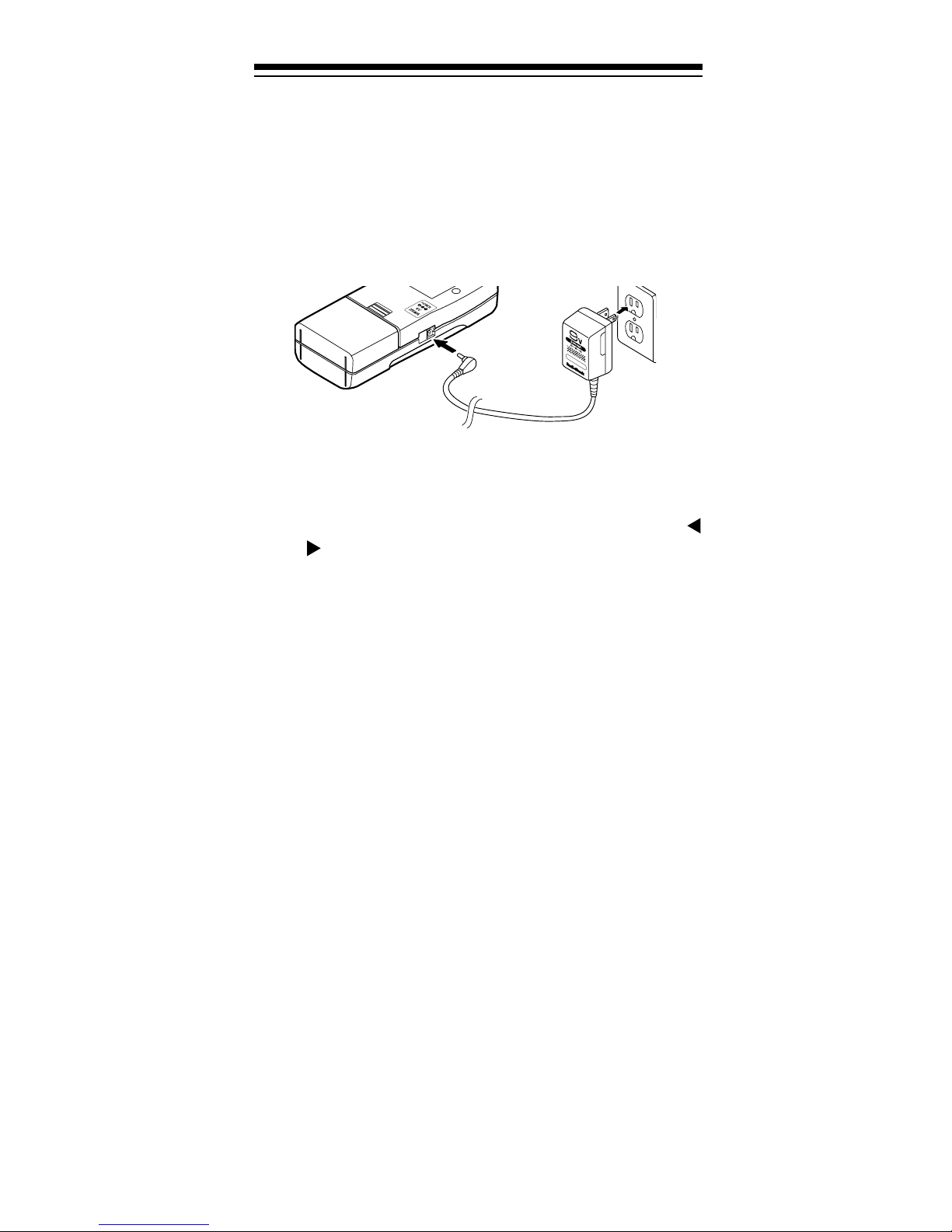
1. Turn
VOLUME/OFF
counterclockwise until it clicks
to make sur e the power is turned off.
2. Plug the adapter’s 3.4 mm outside diameter/1.3
mm inside diameter barrel plug into your scanner’s
POWER
jack.
3. Plug the other end of the adapter into a standard
AC outlet.
If rechargeable batteries are installed and
JACK NI-CD
is set to
NI-CD
, the adapter powers the
ALKALINE
scanner and rec harges the batteries at the same time.
Using Vehicle Battery Power
You can power the scanner from your vehicle’s battery
power using an optional DC adapter such as Cat. No.
270-1560.
Cautions:
• The recommended DC adapter supplies 9 volts
and delivers at least 300 milliamps. It has a barrel
plug with a center negative tip that correctly fits the
scanner’s
not meet these specifications could damage the
scanner or the adapter.
• To protect your vehicle’s electrical system, always
plug the ada pter into the scanner before you plug it
into your vehicle’s cigarette-lighter socket. Alwa ys
unplug the adapter from the vehicle’s cigarettelighter socket before you unplug it from the scanner.
POWER
jack. Using an adapter that does
• If batteries are installed, make sure the battery
switch inside the battery compartment i s set to the
correct position (see “Using Internal Batteries” on
Page 9).
13
Page 14

1. Tur n
VOLUME/OFF
counterclockwise until it clicks
to make sur e the power is turned off.
2. Set the adapt er’ s voltage switch to 9V.
3. Connect the 3.4 mm outer diameter/1.3 mm inner
diameter tip to the ada pter cord, m atching TIP to –.
4. Plug the adapter’s barrel plug into your scanner’s
POWER
jack.
5. Plug the other end of the adapter into your vehicle’s cigarette-lighter socket.
If you have installed rechargeable batteries and
ALKALINE JACK NI-CD
set
to
NI-CD
, the
adapter powers the scanner and recharges the
batteries at the same time.
Note:
If the scanner does not operate properly when
you use a DC adapter, unpl ug the adapter from the c igarette-lighter socket and clean the socket to remove
ashes and debris .
14
Page 15
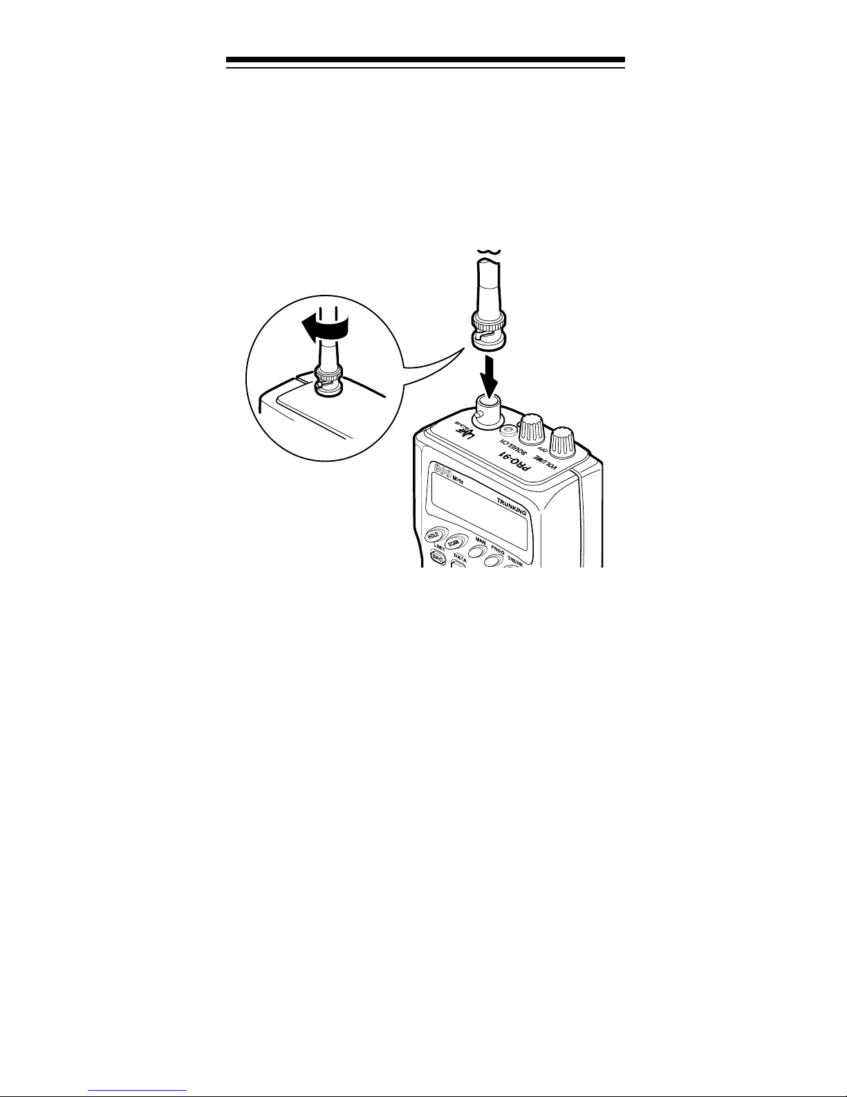
CONNECTING THE ANTENNA
Follow these steps to atta ch the supplied f lexible ant enna to the connect or on the top of your scanner.
1. Align the slots around the antenna’s connec tor with
the tabs on the sca nner’ s BNC connector.
2. Slide the ant enna’s connector down over the scanner’s connec tor and rota te the antenna connector’s
outer ring clockwise until it locks into place.
Connecting an Optional Antenna
The scanner’s BNC connector makes it easy to connect
a variety of optional antennas (such as an external mobile antenna or outdoor base station antenna). Your local RadioShac k store sells a variet y of ant ennas.
Note:
58 or RG-8, to connect an outdoor antenna. If the distance from the scanner to the antenna is over 50 feet,
use RG-8 low-loss dielectric coaxial cable. If your antenna’s cable does not have a BNC connector, your local RadioShack store carries a variety of BNC
adapters.
Always use 50-ohm coaxial cable, such as RG-
15
Page 16
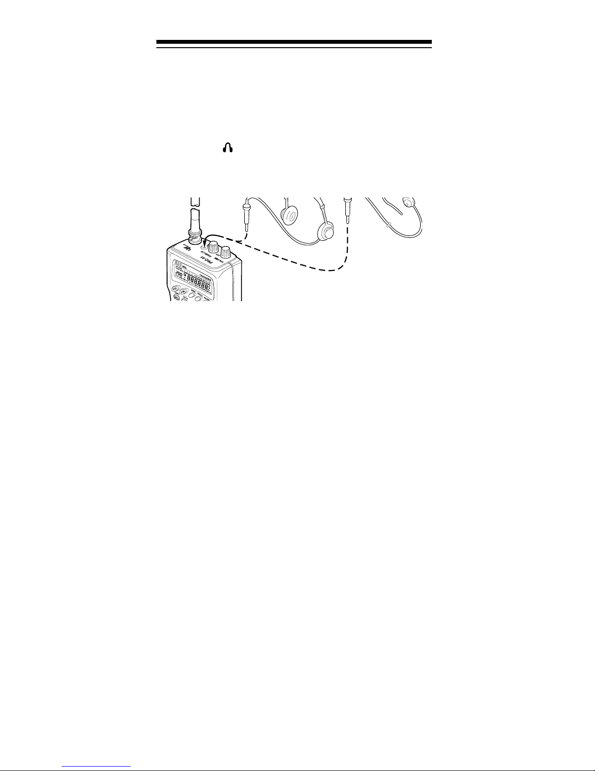
CONNECTING AN EARPHONE/
HEADPHONES
For private listening, you can plug an earphone or
mono headphones (such as Cat. No. 33-178 or 20-
210) into the jack on top of your scanner. This automatica lly disconnects the internal speaker.
Listening Safely
To protect your hearing, follow these guidelines when
you use an earphone or headphones.
• Do not listen at extremely high volume levels.
Extended high-volume listening can lead to permanent hearing loss.
• Set the volume to the lowest setting before you
begin listening. After you begin listening, adjust
the volume to a comfortable level.
• Once you set the volume, do not increase it. Over
time, your ears adapt to the volume level, so a volume level that does not cause discomfort might
still damage your hearing.
Traffic Safety
Do not use an earphone or headphones with your
scanner when operating a motor vehicle in or near traffic. Doing so can create a t raffic hazar d and could be illegal in some areas.
If you use an earphone or headphones with your scanner, be very careful. Do not listen to a continuous
broadcast. Even though some earphones/headphones
let you hear some outside sounds when listening at
normal volume levels, they still can present a traffic
hazard.
16
Page 17

CONNECTING AN EXTENSION
SPEAKER
In a noisy area, an extensi on speaker (such as Cat. No.
21-549), positioned in the right place, might provide
more comfortable listening. Plug the speaker cable’s
1
/8-inch mini-plug into your scanner’s jack.
ATTACHING THE BELT CLIP
You can attach the supplied belt clip to make your
scanner easier to use when you are on the go. Use a
Phillips screwdriver and the supplied screws to attach
the belt clip to the scanner . Then slid e the clip over your
belt or waistband.
17
Page 18

ABOUT YOUR SCANNER
Once you understand a few simple terms we use in thi s
manual and familiarize yourself with your scanner’s
features, you can put the scanner to work for you. You
simply determ ine the type of communicat ions you want
to receive, then set the scanner to scan those communications.
frequency
A
pressed in kHz or MHz). To find active frequencies,
you use the
Besides searching within a frequency range you determine, you can also search your scanner’s
banks
categori zed by type of service. For example, many amateur rad io frequenci es are located in the
bank.
. Service banks are preset groups of frequencie s
is the tuning location of a station (ex-
search
function.
HAM2
service
servic e
When you find a frequency, you can store it into a programmable memory location called a
nels are grouped into
scanner has 5 channel-storage banks of 30 channels
each). You can then
to see if there is activity on the frequencies stored
there.
Or, when you find a frequency, you can store it into a
temporary memory location called a monitor memory
until you decide whether or not to move it to a chan nel.
Just keep in mind — you
channels.
You can also use your scanner to track trunked transmissions (s ee “Trunk Tracking” on Page 39).
channel-storage banks
scan
the channel-storage banks
search
frequencies and
channel
. Chan-
. (This
scan
18
Page 19

A LOOK AT THE KEYPAD
Your scanner’s keys might seem confusing at first, but
this information should help you understand each key’s
function.
HOLD
— holds the frequency search; holds on the cur-
rent ID in the trunk tracking mode.
SCAN
MAN (manual)
— scans through the stored channels.
— stops scanning and lets you directly
enter a channel number or frequency.
PROG (program)
— stores frequencies into channels;
programs the trunking frequency, fleet map, and ID
memories.
TRUNK
— switches between conventional and trunk
tracking.
LIMIT/SRC (search )
— starts a limit search; searches a
specifi ed frequency range to find frequencies; searches
for another active ID while trunk t racking.
DATA
— turns on or off the data signal skip feature;
moves through menu settings while trunk tracking.
PRIORITY/H/S (Hypersearch)
the priorit y feature
L-OUT/S/S (search skip)
channels or skip specified frequencies during a search;
lets you lock out a selected ID while trunk tracking.
KEYLOCK/
tal program changes; turns on the display light for 15
seconds.
—sets and turns on and off
;
turns on and of f Hypersearch.
— lets you lock out selected
— locks the keypad to prevent acciden-
19
Page 20

DELAY
channel, a limit sear ch, or each service scan; programs
a 5-second delay whil e trunk tracking.
t — searches down through a selected frequency
range during a frequency search; selects options during progr am operation; changes the ID loc ati on number
while trunk tracking.
s — searches up through a selected frequency range
during a frequency search; selects options during program operation; changes the ID location number while
trunk tracking.
Number Keys — each key has a single-digit label and a
range of numbers. The single digits are used to enter a
channel, frequency, service bank, or ID number. The
range of numbers (31–60, for example) ar e used to enter the channels that make up a memory bank.
— programs a 2-second delay for the selected
MON/CLEAR/
ories during a search; recalls frequencies from monitor
memories when programming a channel; stores
searched IDs into monitor memories or selects options
while trunk tracking; enters a decimal point or cle ars an
incorrec t ent ry.
SVC (service)/E (ente r)
enters frequencies into channel s.
— stores frequencies into monitor mem-
•
— starts a service bank search;
A LOOK AT THE DISPLAY
The display has indicators that show the scanner’s current operating status. A good look at the display will
help you understand how your scanner operates.
BANK
show which channel-storage banks are turned on for
scanning.
TRUNK
tracking.
20
— appears with numbers (1–5). The numbers
— appears when the scanner is set for trunk
Page 21

(trunking channe l acti vity bar s) — each rep resents a
received trunking frequency or a data frequency while
trunk tracki ng (s ee “Channel Act ivi ty Bars” on Page 47).
— appears when the weather service band is se-
-1-
lected.
— appears when the amateur radio service band
-2-
is selected.
— appears when the marine service band is se-
-3-
lected.
— appears when the air service band i s selected.
-4-
— appears when the poli ce service band is select-
-5-
ed.
— appears when a priority channel is selected.
P
BATT. Lo
DATA
SCAN
LIST
tracking. Numbers with a bar under them show which
ID scan list banks are turned on for scanning.
SVC
SEARCH
search, and blinks when you monitor I D s (see “Monitoring IDs” on Page 46).
— appears when the priority feature is tur ned on.
PRI
HOLD
or when the scanner is holding during a search.
— blinks when the scanner’s battery is low.
— appears when the data ski p function is activ e.
— appears when you scan channels.
— appears with numbers (1–5) during trunk
— appears during a service search.
— appears during a limit search and ID
— appears when you manually select a channel
— appears when you program a delay.
DLY
— appear s when you manually sel ect a channel or
L/O
frequency you locked out.
(keylock) — appears when you lock the keypad.
K/L
Error
— appears when you make an ent ry error.
21
Page 22

MON
select a monitor memory. The number to the right of
this indicator shows the current monitor memory num ber.
— appears during search modes or when you
— appears when you press
MAN
— appears while you store a frequency into a
PGM
channel, while you enter a frequency range during a
limit search, or when you program trunking frequencies, fleet maps, or ID memories while trunk tracking.
HYPER
is active during a direct or limit search.
t and s — appears during a limit, direct, or service
search, in dicating the search direction.
— appears when the battery save function is active
S
(during con ventional scanning only).
— appears while Hyperscan or Hypersearch
MAN
.
UNDERSTANDING BANKS
Service Banks
The scanner i s preprogrammed with all the frequencie s
allocated to the weather, ham, marine, aircraft, and police (fire/emergency) services. This is handy for quickly
finding active frequencies instead of doing a limit
search (see “Se rvice Bank Search” on Page 28).
Channel Storage Banks
To make it easier to identify and select the channels
you want to listen to, channels are divided into 5 banks
of 30 channels each. Use each channel-storage bank
to group frequencies, such as those for the police department, fire department, ambulance services, or aircraft (see “Guide to the Action Bands” on Page 58).
For example, the police department might use four frequencies, one for each side of town. You could program the police frequencies starting with Channel 1
(the first channel in bank 1) , and program the fire department frequencies starting with Channel 31 (the first
channel in bank 2).
22
Page 23

Monitor Memories
The scanner also has 5 temporary memory locations
called monitor memories. You can use these monitor
memories to temporarily store frequencies while you
decide whether to store them into a channel. This is
handy for quickly storing an active frequency when you
search thr ough an entire band ( see “Searching For and
Temporaril y Storing Active Frequencies” on Page 26).
While you are searching frequencies, the 5 numbers at
the top of the display indicate the 5 monitor memories.
appears and the number beside it that flashes in-
MON
dicates t he currently active monitor m em ory.
23
Page 24

OPERATION
TURNING ON THE SCANNER
AND SETTING SQUELCH
Note:
before you turn it on.
Make sure the scanner’s antenna is connected
1. Turn
2. Turn
SQUELCH
VOLUME/OFF
hear a hissing sound.
fully counterclockwise.
clockwise until it clicks and you
3. Press
scanning, turn
set to a point just after the hissing sound stops.
24
MAN
(manual) to stop the scanner from
SQUELCH
clockwise, then leave it
Page 25

STORING KNOWN FREQUENCIES
INTO CHANNELS
Good references for active frequencies are RadioShack's “Beyond Police Call,” “Aeronautical Frequency Directory,” and “Maritime Frequency Directory.”
We update these directories every year, so be sure to
get a current copy.
Follow these steps to store frequencies into channels.
1. Press
MAN
, enter the channel number where you
want to store a frequency, then press
channel number appears.
2. Use the number keys and
•
to enter the frequency
(including the decimal point) you want to store.
1
3. Press
E
to store the frequency into the channel.
PROG
. The
Notes:
• If you entered an invalid frequency in Step 2,
Error
times. Simply enter the frequency again.
appears and the scanner beeps three
25
Page 26

• Your scanner automatically rounds the entered
frequency to the nearest valid frequency. For
example, if you enter a frequency of 151.473,
your scanner accepts it as 151. 475.
• Press
seconds afte r a tr ansmission ends before it proceeds to the next channel (see “Delay” on
Page 33). The scanner also stores this setting
in the channel.
4. If you want to program the next channel in
sequence, press
DELAY
if you want the scanner to pause 2
PROG
and repeat Ste ps 2 and 3.
SEARCHING FOR AND
TEMPORARILY STORING ACTIVE
FREQUENCIES
If you do not have a reference to frequencies in your
area, use a limit, direct, or service search to find a
transmission. Also see “Guide to the Action Bands” on
Page 58.
Notes:
search, you can pr ess
While doing a limit, direct, or service bank
:
DELAY
•
after a transmission ends before it proceeds to the
next frequen cy (see “Delay” on Page 33).
DATA
• if you want the scanner to skip data signals
(such as fax or modem signals) and search only
for audio (voice) signals (see “Skipping Data Signals” on Page 38).
if you wa nt the scanner to pause 2 seconds
Limi t Search
A limit search lets you search within a specific range
of frequencies.
1. Press
appear.
PROG
appears during a limit search.
-L-
, then
LIMIT
.
and
Lo
29.000 MHz
26
Page 27

2. Enter the frequency that is the lower limit of the
range you want to search (including the decimal
point), then press
3. Press
LIMIT
.Hi and
E
.
956.000 MHz
appear.
4. Enter the frequency that is the upper limit of the
range you want to search (including the decimal
E
point), then press
again.
5. Press t to search from the upper to the lower limit,
or s to search from the lower to the upper limit.
6. When the scanner stops
on a transmission,
quickly pres s either:
HOLD
•
to stop searching so you can listen
to the transmission.
HOLD
MON/CLEAR
•
appears.
to store
the displayed frequency into the current monitor memory.
To release hold and continue searching, press
HOLD
or hold down t or s for at least 1 second. Or,
if you did not press
HOLD
, simply press t or s to
continue searching.
Direct Search
Direct search lets you search up or down from the currently displayed frequency.
1. Press
MAN
.
2. Use the number keys to enter the frequency you
want to start the search from. Press
decimal poi nt.
to enter a
•
27
Page 28

Notes:
• If you want to start the search from a frequency
already stored in one of your scanner’s channels, press
to enter the channel number, then press
PROG
again.
MAN
or
PROG
, use the number keys
or
MAN
• If you enter an invalid frequency, the scanner
displays
Error
. Simply re pe a t th is step.
3. Press t to search downward or s to search upward
from the selected frequency.
-d-,SEARCH
, and t
or s appear.
4. When the scanner stops on a transmission,
quickly pr ess either:
•
•
to stop searching so you can listen to the
HOLD
transmission.
MON/CLEAR
HOLD
to store the displayed frequency
appears.
into the current monitor memory.
To release hold and continue searching, press
HOLD
if y ou did not press
or hold down t or s for at least 1 second. Or,
HOLD
, simply press t or s to
continue searching.
Note: To step through t he frequencies whi le
HOLD
is displayed, press t or s.
Service Bank Search
You can search for weather, ham, marine, aircraft, or
police (fire/emergency) transmissions even if you do
not know the specific frequencies being used in your
area. The scanner is preprogrammed with all the frequencies allocated to these services. To use this feature, press
searches through the weather service band. To select
a diffe rent service bank, press the desired service bank
key (
WX1,HAM2,MRN3,AIR4
sponding service band number (
or
) appears, and the scanner starts searching the
-5-
band.
SVC
.
appears and the scanner
SVC
, or
). The corre-
POL5
-1-,-2-,-3-,-4-
,
28
Page 29

When the scanner stops on a transmission, quickly
press either:
HOLD
•
to stop searching so you can listen to the
transmission.
HOLD
appears.
MON/CLEAR
•
to store the displayed frequency into
the current mo nit or memory.
To release hold and continue searching, press
HOLD
or hold down t or s for at least 1 second. Or,
if you did not press
HOLD
, simply press t or s to
continue searching.
Note:
Because there are many different frequencies allocated to fire and police departments, it takes several
minutes to search all these frequencies.
Search Skip Memory
You can skip up to 20 specified frequencies during a
limit or dire ct sear ch and up to 20 speci fied frequencies
during a service bank search. This lets you avoid unwanted frequencies or ones you have already stored in
a channel.
To skip a frequency, press
S/S
when the scanner
stops on the freq uency during a limit, direct, or se rvi ce
search. The scanner stores
the frequency in memory
and automatically resumes the search.
To clear a single frequency from skip memory so the
scanner once again stops on it during a limit, direct, or
service bank search:
1. Press
2. Press t or s to select the frequency.
3. Press
To clear all the skip frequencies at once while searching, press
beeps twice (a bout 3 seconds).
HOLD
to hold the search.
S/S
.
HOLD
disappears.
L/O
, then hold down
ap-pears.
L/O
S/S
until the scanner
29
Page 30

Notes:
• If you marked all fr equencies to be ski pped within
the search range, the scanner beeps 3 times and
does not search.
• If you program more than 20 frequencies to skip,
each new frequency replaces one you already
stored, starting from the first frequency you stored.
• Press t or s to select a skipped frequency while
HOLD
skipped frequency.
appears.
appears when you select a
L/O
LISTENING TO THE MONITOR
MEMORIES
You can listen to the frequency you stored in any
one of the five monitor
memories by pressing
MAN,MON/CLEAR
the number of the monitor memory you want to
listen to (1–5).
, then
Note: To listen to the
monitor memories, the
priority channel feature
must be turned off (see
“Priority” on Page 34).
MOVING A FREQUENCY FROM A
MONITOR MEMORY TO A
CHANNEL
1. Press
appears.
2. Enter the number of
the channel where
you want to store
the frequency in a
monitor memory,
then press
appears.
PGM
MAN
.
PROG
MAN
.
30
Page 31

3. Press
monitor memory that contains the frequency you
want to store.
MON/CLEAR
and enter the number of the
4. Press
selected channel.
E
. The scanner stores the frequency into the
SCANNING THE STORED
CHANNELS
To begin scanning channels, press
scans through all non-locked channels in the activated
banks. (See “Locking Out Channels” on Page 34 and
“Turning Channel-Storage Banks On and Off” on
Page 33). When the scanner finds a transmission, it
stops on it. When the transmission ends, the scanner
resumes scanning.
Notes:
• If you have not stored frequencies into any channels, the scanner does not scan.
• If the scanner picks up unwanted, partial, or very
weak transmissions, turn
decrease the scanner's sensitivity to these signals.
If you want to listen to a weak or distant station,
turn
SQUELCH
counterclockwise.
SCAN
SQUELCH
. The scanner
clockwise to
•If
SQUELCH
ing sound, th e scanner does not scan properly.
• To scan in the trunk tracking mode, see “Scanning
a Trunked Bank” on Page 43.
is adjusted so you always hear a hiss-
MANUALLY SELECTING A
CHANNEL
You can continuously monitor a single channel without
scanning. This is useful if you hear an emergency
broadcast on a channel and do not want to miss any
details — even though there might be periods of silence
— or if you want to monitor a specific chann el.
Follow these steps to manually select a channel.
1. Press
2. Enter the channel number.
3. Press
MAN
MAN
.
again.
31
Page 32

Or, if y our scanner is scanning and stops at the desired
channel, press
MAN
one time. (Pressing
MAN
additional times causes your scanner to step through the channels.)
To resume automatic scan ning, press
SCAN
.
32
Page 33

SPECI AL F EATURES
DELAY
Many agencies use a two-way radio system that might
have a period of 2 or more seconds between a query
and a reply. To keep from missing a reply on a specific
channel, you can program a 2-second delay into any
channel or frequency. The scanner continues to monitor the channel frequency for 2 seconds after the transmission stops before resuming scanning or searching.
To program a 2-second delay:
• If the scanner is
scanning and stops
on an active channel
where you want to
store a delay, quickly
press
continues scanning
again.
DELAY
DLY
before it
appears.
• If the desired channel is not selected, manually
select the channel, then press
pears.
• If the scanner is searching, press
scanner is searchi ng.
ner automatically adds a 2-second delay to every
frequency it stops on in that band.
To turn off the 2-second delay, press
scanner is monitoring a channel, scanning, or searching.
disappears .
DLY
appears and the scan-
DLY
DELAY
DELAY
DELAY
.
ap-
DLY
while the
while the
TURNING CHANNEL-STORAGE
BANKS ON AND OFF
You can turn each channel-storage bank on and off.
When you turn off a bank, the scanner does not scan
any of the 30 channels in that bank.
While scanning, pr ess the number key t hat corresponds
to the bank you want to turn on or off. Numbers appear
at the top of the display, showing the currently selected
banks.
33
Page 34

The scanner scans all the channels within the displayed banks that are not locked out (see “Locking Out
Channels”).
Notes:
• You can manually select any channel within a
bank, even if that bank is turned off.
• You cannot turn off all banks. One bank must
always be active.
LOCKING OUT CHANNELS
You can increase the scanning speed by locking out
channels that have a continuous transmission, such as
a weather channel. To lock out a channel, manually
select the channe l, then press
Note: You can still manually select locked out channels.
L-OUT
.
L/O
appears.
To remove the lockout from a channel, manually select
the channel, then press
To unlock all channels in the banks that are turned on,
press
til the scanner beeps twice.
to stop scanning, then hold down
MAN
S/S
.
L/O
disappears.
L-OUT
un-
PRIORITY
The priority feature let s you scan through channels and
still not miss important or interesting calls on specific
channels. You can program one stored channel in each
bank as a priority channel (for up to a total of 5 stored
channels). If the priority feature is turned on, as the
scanner scans the bank, it checks that bank’s priority
channel every 2 seconds for activity.
The scanner automati cally designates each bank's first
channel as its priority channel. Follow these steps to
select a different channel in a bank a s the prior it y channel.
34
Page 35

1. Press
PROG
.
2. Enter the channel number you want to select as
the priority channel, then press
PRIORITY
.
P
appears to the right of the channel number.
3. Repeat Steps 1 and 2 for the channel in each bank
you want to program as a priority channel.
To review all priority channels, press
peatedly press
PRIORITY
to see the numbers of the pri-
PROG
, then reority cha nnels.
To turn on the priority feature, press
scanning.
appears. Every 2 seconds the scanner
PRI
PRIORITY
during
checks the priority channel in each bank that is turned
on.
To turn off the priority feature, press
PRIORITY
.
PRI
disappears.
Notes:
• The priority feature must be turned off to listen to
the monitor memories or to use the data skip feature.
• You can lock out priority channels. If you
lock out all priority
channels,
LOC OUt
appears when you
turn on the priority
feature.
35
Page 36

USING THE KEYLOCK
Once you program your scanner, you can protect it
from accidental program changes by turning on the
keylock feature. When locked, the only controls that
operate are
SQUELCH
SCAN,MAN,KEYLOCK,VOLUME/OFF
.
, and
Note:
scanning channels.
To turn on the keylock, hold down
appears. To turn it off, hold down
disappears.
The keylock does not prevent the scanner from
KEYLOCK
KEYLOCK
until
until
K/L
K/L
USING THE DISPLAY BACKLIGHT
You can turn on the display light for easy viewing at
night. Press to turn on the display light for 15 seconds. To turn off the light before 15 seconds elapse,
press the button again.
CHANGING SEARCH SPEEDS
The PRO-91 has two search speeds.
Normal Search Hypersearch
100 steps/second 300 steps/second
To switch between the normal and Hypersearch
speeds during limit search or direct search, press
HYPER
Note:
bands (29–54 MHz and 137–174 MHz).
36
appears durin g Hypersearch.
You can use Hyper search only in the 5 kHz step
H/S
.
Page 37

TURNING THE KEY TONE OFF/ON
To turn off the key to ne, follow these steps.
1. Turn off the scanner.
2. While holding down
ner.
OFF bEEP
To turn the key tone back on, repeat these steps.
bEEP
appears.
L-OUT/S/S,
appears.
turn on the scan-
on
TURNING THE BATTERY SAVE
FUNCTION OFF/ON
To save battery power when a channel is manually selected or while you program the scanner, the scanner
automatically sets itself to a standby (battery save)
mode if no button is pressed for more than 5 seconds
and no signal is received. appears when battery
save is set to on.
S
While the battery save mode is set to on, the scanner
repeatedly turns off the internal power for 1 second,
then turns it back on for about
transmission.
The scanner i s preset with the battery save mode set to
on, but you can turn it off or back on.
Note:
ity function is on, even if a channel is manually selected.
To turn the battery save function off or back on, turn off
the scanner, then hold down
scanner.
The battery save mode does not work if the prior-
•
OFF SAVE
been turned off.
•
on SAVE
been turned on.
briefly appears when battery save has
briefly appears when battery save has
1
/2 second to check for a
PRIORITY
and turn on the
37
Page 38

SKIPPING DATA SIGNALS
A
A
You can set the scanner so it skips nonmodulated or
data signals (such as fax or modem transmissions)
during a search or scan.
Note:
air band, this f eature does not work in the air band.
To turn on the data skip feature, be sure the priority
feature is turned off (see “Priority” on Page 34), then
press . appears. To turn off the feature,
press again. disapp ears.
Since data signals are not generally found in the
DATA
DATA
DAT
DAT
38
Page 39

TRUNK TRACKING
Your scanner is desig ned to track transmis sions on Motorola Type I, Type II, and hybrid analog trunking systems, which are extensively used in 800 MHz
communications. Remember these important points
when tracking transmissions:
• Your scanner monitors Type I I systems by default.
However, you can change this if the system in your
area is different (see “Types of Trunking Systems”
below and “Scanning Type I and Hybrid Trunked
Systems” on Page 50 for more infor m ation).
• Your scanner cannot track transmissions on nonMotoro la trunking systems.
• Your scanner cannot track an 800 MHz trunked
system and scan conventional frequencies at the
same time.
• The frequencies for many of the 800 MHz public
safety systems are listed in the separate “National
Public Safety Trunked System Frequency Guide”
included with your PRO-91.
TYPES OF TRUNKING SYSTEMS
Your trunk tr acking scanner can monitor tw o basic types
of systems —
specific frequency to transmit on, a trunked system
chooses one of several frequencies in a 2-wa y radio user’s talk group when that user presses PTT (push to
talk). Thus, trunking systems allocate a few frequencies
among many different users, but the way Type I and
Type I I systems do this is slig htly dif ferent. O ne impor tant distinction between these systems is the amount of
data transmitted by each radio when its push-to-talk
(PTT) button is pressed. In a Type I system, the radio’s
ID and its cur rent aff iliation ( the tr unk sy stem it belong s
to) ar e both transmi tted. I n a Type II sys tem, only the radio’s ID is transmitted.
Why the difference? In Type I systems, each radio in
the trunk group individually transmits its own affiliation,
while the trunk system maintai ns a database that determines each radio's affili ation(s) in Type II systems.
Type I
and
Typ e II
. Inst ead o f sel ec tin g a
Another difference bet ween the systems is that Type I
systems are arranged in a fleet-subfleet hierarchy. For
example, it is possible for a city using a Type I system
to designate 4 fleets, each with 8 subfleets.
39
Page 40

The fleets might be the police department, the fire department, utilities, and city administration. The police
might decide to further divide its fleet into subfleets
such as dispatch, tactical operations, detectives, north,
south, east and west side patrols, and supervisors. All
the available police radios would then be assigned to
one of the police subfleets, letting the police centralize
their communications and control the type of users on
a single system. Determining the exact fleet-subfleet
hierarchy for a particular area is referred to as fleet
map programming.
The disadvantage of a Type I system is that the brief
burst of data sent when a user transmits must contain
the radio’s ID and its fleet and subfleet. This is three
times the amount of data a Type II system radio sends.
Since the data cap acity of Type I system s is limite d and
the amount of data increases with each user, Type I
systems usually accommodate fewer users than Type
II systems. Nevertheless, Type I systems are still in
use.
There are also
of both Type I and Type II. Your scanner defaults to
monitor Type II systems, but you can change to Type I
or a hybrid of Type I and Type II syst em s by selecting a
preprogrammed fleet map or creating a custom fleet
map for your area (see “Scanning Type I and Hybrid
Trunked Systems” on Page 50).
You do not need to determine the fleet-subfleet hierarchy for Type II systems unless you are tracking hybrid
systems that contain both Type I and Type II systems.
hybrid
systems which are a combinat ion
SETTING THE SCANNER TO THE
TRUNK TRACKING MODE
Press
and trunk tracking.
TRUNK
to switch between conventional scanning
40
Page 41

SETTING SQUELCH FOR THE
TRUNK TRACKING MODE
Your scanner’s squelch setting is automatically adjusted during trunk tracking, which means it is not necessary to manually adjust squelch while tracking trunked
transmissions. However, the squelch setting can affect
how fast your scanner acquires the data channel , and,
in some instances, can prevent your scanner from acquiring the data channel at all.
We recommend you set
selecti ng a trunked bank.
Note:
vide bett er per formance in your area.
You can change this setting, if necessary, to pro-
SQUELCH
to this position before
STORING TRUNKED
FREQUENCIES
Before you set up your scanner to track a trunked system, consider the following:
• Valid trunked system frequencies range from
851.0000–868.9875 in 12.5 kHz steps.
• You can use any of your scanner’s banks as either
a trunk tracking bank or conventional scanning
bank, but you cannot mix the two.
• The scanner only scans one trunked system at a
time. Although you can store frequencies for more
than one trunked system in one of your scanner’s
banks, the scanner only scans the frequencies
associated with the first data channel it finds.
41
Page 42

Before scanning a trunked system ’s transmissions, you
must store the trunked system’s frequencies in one of
the banks in your scanner by following the se steps.
1. Press
PROG
then
TRUNK
.
TRUNK
appears and
one or more bank numbers fl ash.
2. Select the bank you want to store the trunked system’s frequencies in by pressing a number key.
The scanner automatical ly selects the first channel
in the bank when you select the bank.
3. Use the number keys to enter one of the trunked
system’s frequencies, then press
BANK
and the bank number, the channel number,
E
.
TRUNK,
and the frequen cy appear.
Note:
scanner beeps, the channel number flashes and
Error
the frequency, then repeat this step.
4. Press either
in the bank.
5. Repeat Steps 3 and 4 until all frequencies have
been entered in that bank.
42
If you entered an invalid frequency, the
appears. If this happens, press • to clear
PROG
or s to sel ect the next channel
Page 43

6. Press
SRC
to begin
searching for the trunk’s
data channel (the channel
that controls the trunk).
SEARCH
flashes as the
scanner searches for the
data channel .
While the scanner looks through the frequencies,
you see them on the display. When the scanner
finds the data channel, it begins t runk tracking.
SCANNING A TRUNKED BANK
You can scan one trunked bank at a time. Once you
have stored frequencies for a trunked system in one or
more of the 5 available banks and you are scanning
conventional (non-trunked) frequencies, follow these
steps to begin trunk scanning.
1. Press
along with
TRUNK
BANK
. The numbers for all banks flash,
and
TRUNK
.
2. Use the number keys to enter the number for the
trunked bank you want to scan, then press
SRC
The scanner searches for a data channel. When
the scanner finds it, it begi ns trunk tracki ng.
If you entered all of the trunk’s frequencies, you
should be able to follow conversations between
broadcasters even when they change frequencies. IDs, which represent different service
grou ps , a pp ear.
.
3. To return to conventional scanning, press
again.
ID
TRUNK
43
Page 44

Hint: While scanning, you will not know exactly who
the IDs are assigned to until you listen awhile or until
you locate ID lists in frequency guides or on internet
sites such as
minutes, you can usually figure out if what you are listening to is a police, fire, or emergency medical 2-way
radio user. Other IDs might take some time, but determining who each ID represents is half the fun of trunk
tracking!
www.trunkscanner.com
. Within a few
Monitoring an Active ID
When the scanner stops on a transmission, you can
hold the scanner on that transmission.
1. Press
stays on the curr ent ID.
2. If you want to listen to a different ID, use the number keys to enter the ID you want to hold.
3. Press
flash and the scanner monitors that I D.
4. When you want to stop the hold and resume
searching for a data channel so you can continue
trunk tracking, press
Note: You can also follow these steps to hold on an ID
while scanning a scan list. See “Scan Lists” on
Page 48.
HOLD
HOLD
.
HOLD
again.
appears and the scanner
HOLD
and the channel num ber
.
SRC
T emporarily Stori ng an ID into the Monitor
ID Memory
1. When your scanner stops on an ID you want to
store, press
ID into the monitor ID memory.
2. Press
Note: To pro gram the ID stor ed in the mo nit or ID memory into the ID scan list, see “Scan Lists” on Page 48.
44
MON/CLEAR
to resume searching.
SRC
. The scanner stores the
Page 45

Locking Out IDs
As with conventional scanning, it is possible to lock out
unwanted traffic. This is particularly important in trunked systems because signals you cannot listen to (such
as water meters, door alarms, traffic signals, and encrypted signals) are assigned IDs just like other users.
You can have up to 100 IDs loc ked out at one time.
Note:
If you lock out an ID while searching, it is also
locked out of the scan list(s). See “Scan Lists” on
Page 48.
To lock out an ID, press
L-OUT
when the ID appears .
The ID is locked out, and the next active I D appears.
Unlocking a Single ID
1. Hold down
2. Repeatedly press t or s to select the ID you want to
unlock.
L-OUT
until you hear two short beeps.
3. Press
The ID is unlocked, and the next locked ID or
–– –––
4. Press
tion.
Unlocking All IDs
Hold down
press
beeps twice.
Note:
pears. Press
lists or press
function. For more information about scan lists, see
“Scan Lists ” on Page 48.
to unlock all the IDs at once. The scanner
E
When you unlock all the IDs, the scan list ap-
L-OUT
.
(if there are no othe r lo cked IDs) appear s.
SRC
to continue the scanner’ s previo us func-
L-OUT
until you hear two short beeps. Then
SCAN
to scan the IDs stored in your scan
SRC
to continue the scanner’s previous
45
Page 46

Using T runk Tracking Scan Delay
Many trunked systems have a period of 2 or more seconds between a query and a reply. You can program a
5-second delay to hold on an ID for 5 seconds to wait
for a reply. The scanner continues to monitor the frequency for 5 seconds after the transm ission stops before resum ing scanning.
Press
DLY
Note:
trunk tracking scan delay set, you might need to
change the default system type or the fleet map you
are using. See “Scanning Type I and Hybrid Trunked
Systems” on Page 50.
DELAY
appears when trunk tracking scan delay is set.
If you consistently miss responses even with
to turn trunk t racking scan delay on or off.
Monitoring IDs
You can use your scanner’s display to monitor the frequencies in a trunked system for activity. You cannot
hear conversations in this mode, but t his is an excellent
way to determine which talk groups are the most active. To set the scanner to monitor IDs, hold down
MON/CLEAR
flash, and all active talk group IDs appear in quick succession. To st op m onitoring IDs, press
Note:
pear.
When you monitor IDs, locked-out IDs also ap-
until
SEARCH
and the channel number
SRC
again.
46
Page 47

CHANNEL ACTIVITY BARS
Your scanner has 20 channel activity indicators (bars)
which show the activity taking place on a trunked system. You can see how many frequencies are being
used and generally monitor how much comm unication
traffic is oc c ur ri n g.
Each frequency you store in a trunking bank has a corresponding activity bar. However, since there are only
20 bars, but you can store up to 30 frequencies, some
bars might indicate more than one frequency if the
trunked system you are scanning has more than 20
channels.
• The bar that remains on steadily even when there
are no current transmissions represents the frequency being used as the data channel.
• The bar that flashes when an ID appears represents the frequency being used by the radio to
transmit what you are currently hearing.
• If a bar turns on but you do not hear a conversation, the channel is probably being used f or a telephone interconnect call or a private call, or the bar
might be a locked-out ID. Your scanner does not
monitor these types of call s.
BANK 2
• If the scanner is holding on an ID which is not
active, the other activity bars turn on and off as
other groups use t he system.
47
Page 48

SCAN LISTS
When you program trunked frequencies into a bank
(see “Storing Trunked Frequencies” on Page 41), your
scanner sets up 5 scan lists into which you can store
your favorite IDs. Each list can contain up to 10 IDs, so
you can store a total of 50 IDs for each trunk tracking
bank (250 IDs if you use all banks as trunking banks!).
Scan list s help you organize t runking system users int o
categori es. For example, you might use List 1 for police
IDs, List 2 for f ire department IDs, List 3 for emergency
medical service IDs, and so on. Once IDs are stored in
lists, you can scan them like you scan conventional
channels. You can program IDs into scan lists manually, during a searc h, or automatically.
Manually Storing IDs into Scan Lists
1. Select the trunking bank you want (see “Scanning
a Trunked Bank” on Page 43).
2. After the scanner begins trunk tracking, press
MAN
. A number showing the current scan list
appears steadily at the top of the display, and bars
which show activity in other banks appear.
3. Press
MAN
then repeatedly press s or t to select
the ID scan list location (shown at the top of the
display) where you want to store an ID. Then,
press
PROG
to select the ID you want to store.
ID Scan List
4. Enter the Type II ID you want to store, then pr ess
E
.
48
Page 49

Or, to enter a T ype I ID:
a. Use the number keys to enter the block number
and fleet number, then press
b. Enter the subfl eet number, then press
.
•
E
.
Note:
press
5. Repeatedly press
To clear a mistake while entering an ID,
0
then E, then start over at Step 1.
PROG
or s to select the next
scan li st location you want to program . Then repeat
Step 4 to enter another ID.
Moving IDs to Scan Lists
1. Press
2. Select the ID scan list location where you want to
store the IDs. Then press
3. Press
4. Press
selected ID scan lists.
MAN
.
MON/CLEAR
E
. The scanner stores the IDs into the
MAN
appears.
PROG
.
PGM
. A monitor ID appears .
appears.
Deleting a Stored ID
1. Press
PROG
.
PGM
appears.
2. Repeatedly press s or t to select the scan list location (shown at the top of the display) you want to
delete.
3. Press
0
then E.
49
Page 50

SCANNING THE SCAN LISTS
Press
stored.
Note:
the display, but your scanner does not stop on an active conversation.
To remove a scan list from active scanning, use the
number keys to enter the scan list’s number. The scan
list number turns off, and the IDs in that list are not
scanned.
Note:
remove all of the scan lists.
To restore a scan list to active scanning, use the num ber keys to enter it s num ber again.
Press
SCAN
to begin scanning the lists you have
If you have not stored any IDs,
One scan list must always be active. You cannot
SRC
to return to the scanner’s previous function.
SCAN
scrolls on
SCANNING TYPE I AND HYBRID
TRUNKED SYSTEMS
Your PRO-91 is set to scan Type II user IDs by default.
When you scan trunked frequencies, each Type II user
ID you see appears as an even number without a dash
(such as 2160). Your PRO-91 can also scan Type I
trunked syst ems. Each Type I ID appears as a thr ee- or
four-digit number, followed by a hyphen, followed by a
one- or two-digit number (such as 200-14). If you notice a mix of odd- and even-user IDs (such as 6477,
2160, 6481, 6144, and 1167), then you are probably
monitoring either a Type I or hybrid (a combination of
Type I and Type II user IDs) system (see “Types of
Trunking Systems” on Page 39).
You might also notice that you are missing responses
when you hold on an active ID. Unlike Type II systems,
Type I and hybrid systems require a fleet map that sets
specific fleet-subfleet parameters. It is easy to select a
fleet map to scan; what is not always easy is selecting
or progr am m ing a map that is being used in your particular area.
50
Page 51

4. Press again.
DATA
5. Repeatedly press s or t to select the name of the
map you want (such as
E1P7
). The prepro-
grammed fleet map appears.
6. Press
E
, then
SRC.
The scanner then searches for
transmissions using th e preset map you chose.
Note:
you see Type I fle et and subfleet IDs such as
100-9,000-12
When the scanner searches for transmissions,
100-12
, or
400-8
.
How do you know if the preset map you selected is correct? Li sten to see if you are follo wing complete conversations. If not, try another preset map.
Programming a Fleet Map
1. Set the scanner for conventional scanning, press
PROG
, then press
2. Select the bank where you want to program the
fleet map by pressing a number key.
3. Press
DATA
.
4. Repeatedly press s or t to select E1, then press
DATA
. A preprogrammed fleet map appears.
TRUNK
.
,
5. Repeatedly press s or t until
press
6. Press .
E
.
DATA
appears. Then
USr
7. Repeatedly press s or t to select the size code for
the first block, then press
E
. The next available
block appears.
Block
8. Repeat Step 7 until you have selected a size code
for each block you want to work with.
51
Page 52

When a Type I system is designed, the address information for all its user IDs is divided into 8 equal-size
blocks, numbered 0–7, and each block is assigned a
size code. When you set up your scanner to track a
Type I system, you must choose a size code for each
block. When you have chosen a size code for all 8
blocks, you will have duplicated the
fleet map
for the
system you are tracking. If you have chosen correctly,
you will be able to tr ack transmissions in that system .
Each size code defines the number of fleets, subfleets,
and IDs each block has. For example, you can see in
the fol lowi ng table th at a size code of S-4 has one fleet,
which is d ivided into 16 separate subfleets, and it has a
total of 512 indi vidual IDs.
Size Fleets Subfleets IDs Blocks
Used
S-0 Reserved block for Type II IDs
S-1 128 4 16 1
S-2 16 8 64 1
S-3 8 8 128 1
S-4 1 16 512 1
S-5 64 4 32 1
S-6 32 8 32 1
S-7 32 4 64 1
S-8 16 4 128 1
S-9 8 4 256 1
S-10 4 8 256 1
S-11 2 16 256 1
S-12 1 16 1024 2
S-13 1 16 2048 4
S-14 1 16 4096 8
Each ID in the block is unique. The left-most digit is the
block number in the ID. The next two digits identify
which fleet is active, and the last digit(s) (after the hyphen) identifies the subfleet.
52
Page 53

The size codes selected by a Type I system designer
depend on the specific needs of the system's users.
Some organizations might want many subfleets with
only a few radios each, while another organization
might want only a few subfleets, with many radios each.
To scan Type I systems, you must select or program a
fleet map with the same size code assignments as the
trunked system. If you do this accurately, you will track
all the fleet and subfleet combinations used by the system. In other w ords, y ou will h ear com plete co mmunications wh ile monitoring a trunked system.
Note: Preset fleet maps might be available at
www.trunkscanner .com
.
If you do no t already know t he size codes used, you will
have to guess them. But since you do not have to figure
out all the blocks at once, this is not as hard as it
seems. Select a size code for a block, then press
SRC
Now listen to the communi cat ions. If you decid e you are
receiving most of the replies to the conversations with
IDs assigned to the block you just programmed, then
you have probably selected the right size code and can
work on the next block of the map.
.
There are 16 pr eset fleet maps t o choose from, and it is
best to start with these when setting up a Type I or hybrid trunk tracking bank. If none of the following preset
fleet maps allow you to follow complete conversations,
then you probably need to program your own fleet map
(see “Progr amm ing a Fleet Map” on Page 51).
E1P1 E1P2 E1P3
Size
Block
0S110S40S4
1S111S41S4
2S112S42S4
3S113S43S4
4S114S44S4
5S115S45S4
6 S11 6 S4 6 S12
Code Block
Size
Code Block
Size
Code
7 S11 7 S4 7 (S12)
53
Page 54

E1P4 E1P5 E1P6
Block
Size
Code Block
Size
Code Block
Size
Code
0S120S40S3
1 (S12) 1 S4 1 S10
2 S4 2 S12 2 S4
3S43(S12)3S4
4S44S44S12
5 S4 5 S4 5 (S12)
6S46S46S12
7 S4 7 S4 7 (S12)
E1P7 E1P8 E1P9
Block
Size
Code Block
Size
Code Block
Size
Code
0S100S10S4
1S101S11S4
2S112S22S0
3S43S23S0
4S44S34S0
5S45S35S0
6S46S46S0
7S47S47S0
E1P10 E1P11 E1P12
Block
Size
Code Block
Size
Code Block
Size
Code
0S00S40S0
1S01S01S0
2S02S02S0
3S03S03S0
4S04S04S0
5S05S05S0
6S46S06S0
7S47S07S4
54
Page 55

E1P13 E1P14
Size
Block
0S30S4
1S31S3
2S112S10
3S43S4
4S44S4
5S05S4
6 S0 6 S12
7 S0 7 S12
Block
0S40S3
Code Block
E1P15 E1P16
Size
Code Block
Size
Code
Size
Code
1 S4 1 S10
2 S4 2 S10
3S113S11
4S114S0
5S05S0
6S126S12
7S127S12
Selecting a Preset Fleet Map
1. Set the scanner for conventional scanning, press
PROG
, then press
2. Select the bank where you want to store the pres et
fleet map by pressing a number key.
3. Press .
DATA
TRUNK
.
4. Repeatedly press s or t to select
flashes, press E.
E1
. Then, when
E1
55
Page 56

9. Press
gramming mode, tunes the data channel, then
begins to search using the map you programmed.
SRC
. The scanner exits the trunking pro-
Note:
restrictions apply:
Since these size codes require multipl e blocks, you will
be prompted for the next available block when programming a fleet map. For example, if you assign
Block 0 as an S-12, the scanner prompts you for
the next block available, instead of b1. And if you assign Block 0 as an S-14, you would not see another
prompt because i t uses all available blocks.
If you select size code S -12, S-13 , or S-14, t hese
• S-12 can only be assigned to Blocks 0, 2, 4, or 6.
• S-13 can only be assigned to Blocks 0 and 4.
• S-14 can only be assigned to Block 0.
b2
Programming a Hybrid System
A hybrid system is simply a Type I system with some of
its blocks designated as Type II blocks. To program a
hybrid system, follow the steps listed i n “Programming
a Fleet Map” on Page 51. However, if you want a bloc k
to be Type II, select size code
S-0
in Step 7.
,
56
Page 57

A GENERAL GUIDE TO SCANNING
Reception of the frequencies covered by your scanner
is mainly “line-of-sight.” That means you usually cannot
hear stations that are beyond the horizon.
GUIDE TO FREQUENCIES
National Weather Frequencies
162.400 162.475 162.525
162.425 162.500 162.550
162.450
Canadian Weather Frequencies
161.650 161.775 163.275
Note:
These frequencies are no t preprogrammed in the
weather service bank but can be manu ally programmed
into a channel.
Birdie Frequencies
Every scanner has birdie frequencies. Birdies are signals created inside the scanner’s receiver. These operating frequencies might interfere with broadcast s on the
same frequencies. I f you program one of these frequencies, you hear only noise on that frequency. If the interference is not severe, you might be able to turn
SQUELCH
This scanner’s birdie frequencies (in MHz) are:
31.2000 41.6000 52.0000 138.7100
138.7150 145.6000 148.6200 165.3000
171.2500 406.2250 407.7625 407.8125
413.1750 413.2250 416.1375 426.0375
426.0500 435.9500 455.7625 455.8625
455.7750 465.6750 475.5875 485.4875
489.2500 495.4000 505.3000 505.3125
813.4000 820.9500 822.3625 899.2375
clockwise to cut out the birdie.
57
Page 58

GUIDE TO THE ACTION BANDS
Typical Band Usage
VHF Band
Low Range 29.00–50.00 MHz
6-Me ter A m ate ur 50. 00 –5 4.00 MH z
U.S. Government 137.00–144.00 MHz
2-Me ter A m ate ur 144. 0 0– 14 8.00 MH z
High Range 148.00–174.00 MHz
UHF Band
U.S. Government 406.00–420.00 MHz
70-cm Amateur 420.00–450.00 MHz
Low Range 450.00–470.00 MHz
FM-TV Audio Broadcast, Wide
Band
Publi c Ser v i ce 8 06 .0 0–823.93 MH z
Conventional Systems 851.00–856.00 MHz
Conventional/Trunked Sys-
tems
Trunked Systems 861.00–866.00 MHz
Public Safety 866.00–868.93 MHz
High Range 896.11–902.00 MHz
33-Centimeter Amateur 902.00–928.00 MHz
Priva te Trun k ed 935. 0 0– 94 0.00 MH z
General Trunked 940.00–941.00 MHz
Fixed Services 941.00–944.00 MHz
Studio-to-Transmitter Broadcast Links
Private Fixed Services, Paging 952.00–956.00 MHz
470.00–512.00 MHz
856.00–861.00 MHz
944.00–952.00 MHz
Primary Usage
As a general rule, most of the radio activity is concentrated on the fol lowing frequencies:
VHF Band
Activities Frequencies
Gover nment, Police, and Fire 153.785–155.980 MHz
Emergency Services 158.730–159.460 MHz
Railr oad 160.000–161.900 MHz
58
Page 59

UHF Band
Activities Frequencies
Land- M ob il e “ Pai r ed ” Frequencies
Base Stations 451.025–454.950 MHz
Mobile Units 456.025–459.950 MHz
Repeater Units 460.025–464.975 MHz
Control Stations 465.025–469.975 MHz
450.000–47 0.000 MHz
Note: Remote control stati ons and mobile units operate
at 5 MHz higher than their as sociated base stations and
relay repe ater units.
BAND ALLOCATION
To help decide which fr eque ncy ranges t o scan, use the
following listing of the typical services that use the frequencies your scanner r eceives. These frequencies are
subject to change, and might vary from area to area.
For a more complete li sting, re fer to the “P olice Call Radio Guide including Fire and Emergency Services,”
available at your local RadioShack store.
Abbreviations Services
BIFC . . . . . . . . . . . . . . . . . Boise (ID) Interagency Fire Cache
BUS. . . . . . . . . . . . . . . . . . . . . . . . . . . . . . . . . . . . . . Business
CAP. . . . . . . . . . . . . . . . . . . . . . . . . . . . . . . . . . Civil Air Patrol
CB . . . . . . . . . . . . . . . . . . . . . . . . . . . . . . . . . . . Citizens Band
CCA. . . . . . . . . . . . . . . . . . . . . . . . . . . . . . . . Common Carrier
CSB. . . . . . . . . . . . . . . . . . . . . . . . . . . Conventional Systems
CTSB. . . . . . . . . . . . . . . . . . . Conventional/Trunked Systems
FIRE . . . . . . . . . . . . . . . . . . . . . . . . . . . . . . . Fire Department
HAM. . . . . . . . . . . . . . . . . . . . . . . . . . . .Amateur (Ham) Radio
GOVT . . . . . . . . . . . . . . . . . . . . . . . . . . .Federal Government
GMR . . . . . . . . . . . . . . . . . . . . . . . . . . .General Mobile Radio
GTR. . . . . . . . . . . . . . . . . . . . . . . . . . . . . . . .General Trunked
IND . . . . . . . . . . . . . . . . . . . . . . . . . . . . . . Industrial Services
. . . (Manufacturing, Construction, Farming, Forest Products)
MAR. . . . . . . . . . . . . . . . . . . . . . . . . . . Military Amateur Radio
MARI . . . . . . . . . . . . . . . . . . . . . . . . . .Maritime Limited Coast
. . . . . . . . . . . . . . . . . . . . . (Coast Guard, Marine T e lephone,
. . . . . . . . . . . . . . . . . . . . .Shipboard Radio, Private Stations)
MARS . . . . . . . . . . . . . . . . . . . Military Affiliate Radio System
MED. . . . . . . . . . . . . . . . . . . . . . Emergency/Medical Services
MIL . . . . . . . . . . . . . . . . . . . . . . . . . . . . . . . . . . . U.S. Military
MOV . . . . . . . . . . . . . . . . . . . . .Motion Picture/Video Industry
NEW . . . . . . . . . . . . . . . . . . . . . . . . . . . . New Mobile Narrow
NEWS . . . . . . . . . . . . . . Relay Press (Newspaper Reporters)
OIL. . . . . . . . . . . . . . . . . . . . . . . . . . . . Oil/Petroleum Industry
POL . . . . . . . . . . . . . . . . . . . . . . . . . . . . . . Police Department
PUB. . . . . . . . . . . . . . . . . . . . . . . . . . . . . . . . . Public Services
. . . . . . . . . . . . . . . . . . . . . . . . . . . . . . . . . . . . . . . . . . . . . . . . (Pub-
lic Safety, Local Government, Forestry Conservation)
PSB . . . . . . . . . . . . . . . . . . . . . . . . . . . . . . . . . . .Public Safety
PTR . . . . . . . . . . . . . . . . . . . . . . . . . . . . . . . . Private Trunked
59
Page 60

ROAD . . . . . . . . . . . . . . . . . . . Road & Highway Maintenance
RTV. . . . . . . . . . . . . . . . .Radio/TV Remote Broadcast Pickup
TAXI . . . . . . . . . . . . . . . . . . . . . . . . . . . . . . . . . . Taxi Services
TELB. . . . . . . . . . . . . . . . . . . . . . . . . . . . . . Mobile Telephone
(Aircraft, Radio Common Carrier, Landli ne Companies)
TELC. . . . . . . . . . . . . . . . . . . . . . . . . . . . . . .Cordless Phones
TELM . . . . . . . . . . . . . . . . . . . . . . . . Telephone Maintenance
TOW . . . . . . . . . . . . . . . . . . . . . . . . . . . . . . . . . . . T o w Trucks
TRAN . . . . . . . . . . . . . . . . . . . . . . . . .Transportation Services
(Trucks, Tow Trucks, Buses, Railroad, Other)
TSB. . . . . . . . . . . . . . . . . . . . . . . . . . . . . . . .Trunked Systems
TVn . . . . . . . . . . . . . . . . . . . . . . . . . . FM-TV Audio Broadcast
USXX . . . . . . . . . . . . . . . . . . . . . . . . . Government Classified
UTIL . . . . . . . . . . . . . . . . . . . . . . . . . . Power & Water Utilities
WTHR . . . . . . . . . . . . . . . . . . . . . . . . . . . . . . . . . . . . .Weather
VERY HIGH FREQUENCY (VHF)
VHF Low Band—(29–50 MH z—in 5 kHz step s)
29.000–29.700 . . . . . . . . . . . . . . . . . . . . . . . . . . . . . . . . HAM
29.900–30.550 . . . . . . . . . . . . . . . . . . . . . . . . . . . .GOVT, MIL
30.580–31.980 . . . . . . . . . . . . . . . . . . . . . . . . . . . . .IND, PUB
32.000–32.990 . . . . . . . . . . . . . . . . . . . . . . . . . . . .GOVT, MIL
33.020–33.980 . . . . . . . . . . . . . . . . . . . . . . . . BUS, IND, PUB
34.010–34.990 . . . . . . . . . . . . . . . . . . . . . . . . . . . .GOVT, MIL
35.020–35.980 . . . . . . . . . . . . . . . . . . BUS, PUB, IND, TELM
36.000–36.230 . . . . . . . . . . . . . . . . . . . . . . . . . . . .GOVT, MIL
36.250. . . . . . . . . . . . . . . . . . . . . . . . . . . . . . Oil Spill Cleanup
36.270–36.990 . . . . . . . . . . . . . . . . . . . . . . . . . . . .GOVT, MIL
37.020–37.980 . . . . . . . . . . . . . . . . . . . . . . . . . . . . .PUB, IND
38.000–39.000 . . . . . . . . . . . . . . . . . . . . . . . . . . . .GOVT, MIL
39.020–39.980 . . . . . . . . . . . . . . . . . . . . . . . . . . . . . . . . .PUB
40.000–42.000 . . . . . . . . . . . . . . . . . . . . . . GOVT, MIL, MARI
42.020–42.940 . . . . . . . . . . . . . . . . . . . . . . . . . . . . . . . . . POL
42.960–43.180 . . . . . . . . . . . . . . . . . . . . . . . . . . . . . . . . . IND
43.220–43.680 . . . . . . . . . . . . . . . . . . . . . . . TELM, IND, PUB
43.700–44.600 . . . . . . . . . . . . . . . . . . . . . . . . . . . . . . . .TRAN
44.620–46.580 . . . . . . . . . . . . . . . . . . . . . . . . . . . . POL, PUB
46.600–46.990 . . . . . . . . . . . . . . . . . . . . . . . . . . GOVT, TELC
47.020–47.400 . . . . . . . . . . . . . . . . . . . . . . . . . . . . . . . . .PUB
47.420. . . . . . . . . . . . . . . . . . . . . . . . . . . American Red Cross
47.440–49.580 . . . . . . . . . . . . . . . . . . . . . . . . . . . . .IND, PUB
49.610–49.990 . . . . . . . . . . . . . . . . . . . . . . . . . . . . MIL, TELC
6-Meter Amateur Band—(50–54 MHz)
50.00–54.00 . . . . . . . . . . . . . . . . . . . . . . . . . . . . . . . . . . HAM
Aircraft Band—(108–137 MHz)
108.00–121.490 . . . . . . . . . . . . . . . . . . . . . . . . . . . . . . . . AIR
121.500. . . . . . . . . . . . . . . . . . . . . . . . . . . . . . AIR Emergency
121.510–136.000 . . . . . . . . . . . . . . . . . . . . . . . . . . . . . . . AIR
U.S. Government Band (137–144 MHz)
137.000–144.000 . . . . . . . . . . . . . . . . . . . . . . . . . .GOVT, MIL
2-Met er Amateur Band ( 144–148 MHz)
144.000–148.000 . . . . . . . . . . . . . . . . . . . . . . . . . . . . . . HAM
VHF High Band (148–174 MHz)
148.050–150.345 . . . . . . . . . . . . . . . . . . . . . . CAP, MAR, MIL
150.775–150.790 . . . . . . . . . . . . . . . . . . . . . . . . . . . . . . MED
150.815–150.980 . . . . . . . . . . . . . . . . TOW, Oil Spill Cleanup
150.995–151.475 . . . . . . . . . . . . . . . . . . . . . . . . .ROAD, POL
151.490–151.955 . . . . . . . . . . . . . . . . . . . . . . . . . . .IND, BUS
151.985. . . . . . . . . . . . . . . . . . . . . . . . . . . . . . . . . . . . . .TELM
60
Page 61

152.0075 . . . . . . . . . . . . . . . . . . . . . . . . . . . . . . . . . . . . . MED
152.030–152.240 . . . . . . . . . . . . . . . . . . . . . . . . . . . . . .TELB
152.270–152.480 . . . . . . . . . . . . . . . . . . . . . IND, TAXI, BUS
152.510–152.840 . . . . . . . . . . . . . . . . . . . . . . . . . . . . . .TELB
152.870–153.020 . . . . . . . . . . . . . . . . . . . . . . . . . . IND, MOV
153.035–153.725 . . . . . . . . . . . . . . . . . . . . . . IND, OIL, UTIL
153.740–154.445 . . . . . . . . . . . . . . . . . . . . . . . . . PUB, FIRE
154.490–154.570 . . . . . . . . . . . . . . . . . . . . . . . . . . IND, BUS
154.585 . . . . . . . . . . . . . . . . . . . . . . . . . . . . . Oil Spill Cleanup
154.600–154.625 . . . . . . . . . . . . . . . . . . . . . . . . . . . . . . BUS
154.655–156.240 . . . . . . . . . . . . . . .MED, ROAD, POL, PUB
156.255–157.425 . . . . . . . . . . . . . . . . . . . . . . . . . .OIL, MARI
157.450 . . . . . . . . . . . . . . . . . . . . . . . . . . . . . . . . . . . . . . MED
157.470–157.515 . . . . . . . . . . . . . . . . . . . . . . . . . . . . . . TOW
157.530–157.725 . . . . . . . . . . . . . . . . . . . . . . . . . . IND, TAXI
157.740 . . . . . . . . . . . . . . . . . . . . . . . . . . . . . . . . . . . . . . BUS
157.770–158.100 . . . . . . . . . . . . . . . . . . . . . . . . . . . . . .TELB
158.130–158.460 . . . . . . . . . . . .BUS, IND, OIL, TELM, UTIL
158.490–158.700 . . . . . . . . . . . . . . . . . . . . . . . . . . . . . .TELB
158.730–159.465 . . . . . . . . . . . . . . . . . . . .POL, PUB, ROAD
159.480 . . . . . . . . . . . . . . . . . . . . . . . . . . . . . . . . . . . . . . . OIL
159.495–161.565 . . . . . . . . . . . . . . . . . . . . . . . . . . . . . TRAN
161.580–162.000 . . . . . . . . . . . . . . . . . . . . . OIL, MARI, RTV
162.0125–162.35 . . . . . . . . . . . . . . . . . . . GOVT, MIL, USXX
162.400–162.550 . . . . . . . . . . . . . . . . . . . . . . . . . . . . .WTHR
162.5625–162.6375 . . . . . . . . . . . . . . . . . GOVT, MIL, USXX
162.6625 . . . . . . . . . . . . . . . . . . . . . . . . . . . . . . . . . . . . . MED
162.6875–163.225 . . . . . . . . . . . . . . . . . . GOVT, MIL, USXX
163.250 . . . . . . . . . . . . . . . . . . . . . . . . . . . . . . . . . . . . . . MED
163.275–166.225 . . . . . . . . . . . . . . . . . . . GOVT, MIL, USXX
166.250 . . . . . . . . . . . . . . . . . . . . . . . . . . . .GOVT, RTV, FIRE
166.275–169.400 . . . . . . . . . . . . . . . . . . . . . . . . GOVT , BIFC
169.445–169.505 . . . . . . . . . . . . . . . . Wireless Mikes, GOVT
169.55–169.9875 . . . . . . . . . . . . . . . . . . . GOVT, MIL, USXX
170.000–170.150 . . . . . . . . . . . . . . .BIFC, GOVT, RTV, FIRE
170.175–170.225 . . . . . . . . . . . . . . . . . . . . . . . . . . . . . GOVT
170.245–170.305 . . . . . . . . . . . . . . . . . . . . . . Wireless Mikes
170.350–170.400 . . . . . . . . . . . . . . . . . . . . . . . . . GOVT, MIL
170.425–170.450 . . . . . . . . . . . . . . . . . . . . . . . . . . . . . . BIFC
170.475 . . . . . . . . . . . . . . . . . . . . . . . . . . . . . . . . . . . . . . PUB
170.4875–173.175 . . . . . . . . . . GOVT, PUB, Wireless Mikes
173.225–173.5375 . . . . . . . . . . . . . . MOV, NEWS, UTIL, MIL
173.5625–173.5875 . . . . . . . . . . . .MIL Medical/Crash Crews
173.60–173.9875 . . . . . . . . . . . . . . . . . . . . . . . . . . . . . GOVT
ULTRA HIGH FREQUENCY (UHF)
U. S. Government Band (406–420 MHz)
406.125–419.975 . . . . . . . . . . . . . . . . . . . . . . . GOVT, USXX
70-cm Amateur Band (4 20–450 MHz)
420.000–450.000 . . . . . . . . . . . . . . . . . . . . . . . . . . . . . . HAM
Low Band (450 –470 MHz)
450.050–450.925 . . . . . . . . . . . . . . . . . . . . . . . . . . . . . . .RTV
451.025–452.025 . . . . . . . . . . . . . . . . IND, OIL, TELM, UTIL
452.0375–453.00 . . . . . . . . . IND, TAXI, TRAN TOW, NEWS
453.0125–454.000 . . . . . . . . . . . . . . . . . . . . . . . . . .PUB, OIL
454.025–454.975 . . . . . . . . . . . . . . . . . . . . . . . . . . . . . .TELB
455.050–455.925 . . . . . . . . . . . . . . . . . . . . . . . . . . . . . . .RTV
457.525–457.600 . . . . . . . . . . . . . . . . . . . . . . . . . . . . . . BUS
458.025–458.175 . . . . . . . . . . . . . . . . . . . . . . . . . . . . . . MED
460.0125–460.6375 . . . . . . . . . . . . . . . . . . . FIRE, POL, PUB
460.650–462.175 . . . . . . . . . . . . . . . . . . . . . . . . . . . . . . BUS
462.1875–462.450 . . . . . . . . . . . . . . . . . . . . . . . . . BUS, IND
462.4625–462.525 . . . . . . . . . . . . . . . IND, OIL, TELM, UTIL
462.550–462.925 . . . . . . . . . . . . . . . . . . . . . . . . . GMR, BUS
61
Page 62

462.9375–463.1875 . . . . . . . . . . . . . . . . . . . . . . . . . . . . MED
463.200–467.925 . . . . . . . . . . . . . . . . . . . . . . . . . . . . . . .BUS
FM-TV Audio Broadcast, UHF Wide Band (470–512 MHz)
(Cha nnels 14 through 69 in 6 MHz steps)
475.750. . . . . . . . . . . . . . . . . . . . . . . . . . . . . . . . . Channel 14
481.750. . . . . . . . . . . . . . . . . . . . . . . . . . . . . . . . . Channel 15
487.750. . . . . . . . . . . . . . . . . . . . . . . . . . . . . . . . . Channel 16
.. . . . . . . . . . . . . . . . . . . . . . . . . . . . . . . . . . . . . . . . . . . . . . . . .
.. . . . . . . . . . . . . . . . . . . . . . . . . . . . . . . . . . . . . . . . . . . . . . . . .
511.750. . . . . . . . . . . . . . . . . . . . . . . . . . . . . . . . . Channel 20
Note:
Some citi es use the 470–512 MHz band for land/
mobile service.
Conventional Systems Band – Locally Assigned
851.0125–855.9875 . . . . . . . . . . . . . . . . . . . . . . . . . . . . .CSB
Conventional/Trunked Systems Band – Locally Assigned
856.0125–860.9875 . . . . . . . . . . . . . . . . . . . . . . . . . . . .CTSB
Trunked Systems Band – Local ly Assigned
861.0125–865.9875 . . . . . . . . . . . . . . . . . . . . . . . . . . . . . TSB
Public Safety Band – Locally Assigned
866.0125–868.9875 . . . . . . . . . . . . . . . . . . . . . . . . . . . . .PSB
33-Centimeter Amateur Band (902–928 MHz)
902.0000–928.0000 . . . . . . . . . . . . . . . . . . . . . . . . . . . . HAM
Private Trun ke d
935.0125–939.9875 . . . . . . . . . . . . . . . . . . . . . . . . . . . . . PTR
General Trunked
940.0125–940.9875 . . . . . . . . . . . . . . . . . . . . . . . . . . . . .GTR
FREQUENCY CONVERSION
The tuning location of a station can be expressed in
frequency ( kHz or MHz) or in wavelength ( m eter s). The
following in formation can help you make the necessary
conversions.
1 MHz (million) = 1,000 kHz (thousand)
To convert MHz to kHz, multiply the number of megahertz by 1,000:
9.62 (MHz) x 1000 = 9620 kHz
To convert from kHz to MHz, divide the number of kilohertz by 1,000:
2780 (kHz) ÷ 1000 = 2.780 MHz
To convert MHz to meters, di vide 300 by the number of
megahertz:
300 ÷ 7.1 MHz = 42.25 meters
62
Page 63

TROUBLESHOOTI NG
If you have problems, here are some suggestions that
might help. If they do not, take your scan ner to your
local RadioShack store for assistance.
PROBLEM
Scanner is on but
will not scan.
Scanner is totally
inoperative.
POSSIBLE
CAUSE
SQUELCH
adjusted correctly.
Only on e channel
or no channels
are stored.
No power. Check the batter-
is not
REMEDY
Turn
SQUELCH
clockwise.
Store frequencies
into more th an
one channel.
ies or make sure
the AC ad apte r or
DC adapter is
connected properly.
Recharge the
rechargeable batteries or replace
the non-rechargeable batteries.
The scanner’s
disp la y di ms or
the scanner
sou nds a tone
every 15
onds.
Keypad does not
work.
30 sec-
–
BATT. Lo
flashes.
The AC adapter
or DC adapter is
not connected.
Batteries are not
correctly
installed.
The ba tteries are
weak.
The keylock function is activated.
The ba tteries are
weak.
Be sure the
adapter’s barrel
plug is fully
plugged into the
POWER
Make sure the
batteries are
installed p roperly.
Recharge the
rechargeable batteries or replace
the non-rechargeable batteries.
To turn off the
keylock, press
KEYLOCK
K/L
Recharge the
rechargeable batteries or replace
the non-rechargeable batteries.
jack.
until
disappear s .
63
Page 64

PROBLEM
POSSIBLE
CAUSE
REMEDY
PROBLEM
Error
appears.
The sc an n er
locks on frequencies that have an
unclear transmission.
Scanner will not
track a trunked
system.
POSSIBLE
CAUSE
An ant enn a is no t
connected or
connected incor rectly.
Programming
error.
Stor ed frequencies are the same
as “birdie” frequencies.
The transmission might not
use a syste m that
can be tracked by
your sc a nner.
REMEDY
Make sure an
antenna is connected to the
scanner.
Re-enter the frequency correctly,
including the decimal point.
Avoid st oring fre quencies listed
under “Birdie Frequencies” on
Page 57 or only
listen to the m
manually.
Scan another
transmission.
Scanner is set to
rece iv e Type I
trunked frequencies, but does
not scan them.
The data frequency is missing.
The system you
are trying to track
is a Type I system, an d the
scanner is set to
scan Type II systems.
The fleet map
you ha ve sel ec t ed or entered
might be incorrect.
Find the data frequency (see
“Storing Trunked
Frequencies” on
Page 41).
Set the s canne r t o
receive Type I
trunked fr equencies. See “Scanning Type I and
Hybr id Trunked
Systems” on
Page 50.
Check the fleet
map an d c or re ct it
if nece ss a r y (see
“Scanning Type I
and Hybrid
Trunked Systems” on Pag e 50
and “Programming a Fleet Map”
on Page 51).
64
Page 65

PROBLEM
POSSIBLE
CAUSE
REMEDY
Scanner will not
stop while scanning a scan list.
Scanner will not
acq uire a data
channel.
No IDs have
been stored.
The IDs you h ave
stored are not
active.
SQUELCH
is not
corre ctly adjus ted
for trunk tracking.
The frequency
used for the data
channel is missing.
Store on e or mo re
IDs (see “Scan
Lists” on Page 48.
Sca n an oth er
transmission.
Adjust sque lc h f o r
trunk tracking.
See “Setting
Squelch for the
Trunk Trac k in g
Mode” on
Page 41.
Press
SRC
to
search for the
data ch an ne l ( s ee
“Storing Trunked
Frequencies” on
Page 41).
Missin g repli es to
conversations.
Missin g repli es to
conversations
(continued)
The system you
are try ing to track
is a Type I system, and the
scanner is set to
scan Type II systems.
The selected
fleet map i s in correct.
Not all of the
trunk’s frequencies have been
entered.
Set th e sca nner t o
receive Type I
trunked frequencies. S ee “Scanning Type I and
Hybri d Trunked
Systems” on
Page 50.
Try another preset
fle et ma p or program your own
fleet map (see
“Sca nning Type I
and Hybrid
Trunke d S y stems” on
Page 50).
Enter all of the
trunk’s frequencies (see “Storing
Trunked Frequencies” on Page 41).
65
Page 66

PROBLEM
POSSIBLE
CAUSE
REMEDY
Channel activity
bars are flashing
but no so un d is
heard.
The transmission might be a
private or telephone interconnect call. The
scanner does not
scan these types
of transmissions.
The ID shown is
not active.
Scan for another
transmission.
Wait for the ID to
become active, or
scan another
transmission.
RESETTING THE SCANNER
If the scanner’s display locks up or does not work properly, you might need to reset the scanner.
Caution:
have stored into the scanner. Before you reset the
scanner, t ry turning it off and on t o see if it beg ins working proper ly. Reset the scanner only when you are sure
it is not worki ng properly.
This procedure clears all the information you
1. Turn off the scanner.
2. While you hold down the
scanner.
CLEAR
flashes for about 8 seconds as
2
and 9 keys, turn on the
the scanner clears its memo ry.
Note:
Do not turn off the scanner until
CLEAR
stops
flashing. Otherwise, the scanner might not clear its
memory properly.
66
Page 67

CARE AND MAINTENANCE
Your RadioShack PRO-91 150-Channel Handheld
Trunking Scanner is an example of superior design and
craftsmanship. The following suggest ions will help you
care for your scanner so you can enjoy it for years.
Keep the scanner dry. If it gets wet, wipe
it dry immediately. Liquids can contain
minerals that can corrode the electronic
circuits.
Use only batteries of the recommended
size and type. Always remove old and
weak batteries. They can leak chemicals
that destroy electronic circuits.
Handle the scanner gently and carefully.
Dropping it can damage circuit boards
and cases and can cause the sc anner to
work improperly.
Use and store the scan ner only in normal
temperature environments. Temperature
extremes can shorten the life of electronic devices, damage batteries, and distort
or melt plastic parts.
Keep the scanner away from dust and
dirt, which can cause premature wear of
parts.
Wipe the scanner with a damp cloth occasionally to keep it looking new. Do not
use harsh chemicals, cleaning solvents,
or strong detergents to clean the scanner.
Modifyin g or tampering with t he scanner’s i nternal components can cause a malfunction, invalidate your scanner’s warranty and void your FCC authorization to
operate it. If your scanner is not operating as it should,
take it to your local RadioShack store for assistance.
67
Page 68

SPECIFICATIONS
Frequency Coverage: ..... 29–5 4 MHz ( in 5 kHz st eps)
108–136.975 MHz (in 12.5 kHz steps)
137–174 MHz (in 5 kHz steps)
406–512 MHz (in 12.5 kHz st eps)
806.0000–823.9375 MHz (in 12.5 kHz st eps)
851.0000–868.9875 MHz (in 12.5 kHz st eps)
896.1125–956.0000 MHz (in 12.5 kHz steps)
Monitor Channels 5
Number of Banks 5
Sens itivity (AM/FM):
NFM: 20 dB S/N at 3 kHz deviation):
29–54 MHz 0.5 µV
137–174 MHz 0.4 µV
406–512 MHz 0.4 µV
806–956 MHz 0.6 µV
AM: 20 dB S/N at 60% modulation):
108–136.9875 MHz 1.5 µV
Spurious Rejection (at 40.84 MHz) 50 dB
Selectivity:
10 kHz –6 dB
15 kHz –50 dB
IF Rejection (at 162.4 MHz) 80 dB
Channels ............................................................... 150
Operating Temperat ure .... –4 to 140
Scan Speed . .............................. 50 Channels/Second
Search Speed:
Normal .................. ................. .... 100 St eps/Second
Hypersear ch ...... ........ ................ 300 Steps/Second
Serv ic e ....... .. ... ............ ...... 50 F re q ue n c ie s /S e c on d
Priority Sampling ........................................ 2 Seconds
Delay Time ................................................. 2 Seconds
IF Frequencies 380.7 MHz, 10.85 MHz, and 450 kHz
Antenna Impedance 50 Ohms
F (–20 to 60° C)
°
Audio Output ................................. 350 mW maximum
Built-in Speaker ...............1
Maximum Current Drain ...... .. ................... ....... 180 mA
68
7
/16 Inches (36 mm) 8 Ohm,
Dynamic Type
Page 69

Power Requirement:
4 AA Alkaline Batteries (6.0 VDC),
or 4 AA Rechargeable Ni-Cd Batteries (4.8 VDC),
or AC Adapter (Cat. No. 273-1665),
or DC Adapter (Cat. No. 270-1560)
Current Drain:
Squelched .................................................. 70 mA
Full Output ....... ................. ......... .. ........ .. .. 180 mA
Dimensions (HWD) ............... 6
1
1
4
× 2
/
/2× 19/16 Inch es
(158 × 63 × 40 mm)
Weight (wi thout antenna, bat teries, belt cl ip) ..... 8.1 oz
(229 g)
Specifications are typical; individual units might vary.
Specifications are subject to change and improvement
without notic e.
69
Page 70

NOTES
70
Page 71

71
Page 72

Limited On e-Year Warranty
y
y
g
y
y
g
y
y
g
g
y
y
g
y
y
g
g
g
y
g
j
yg
g
This product is w arranted by RadioShac k against manuf acturing defects in material and workmans hi p under nor mal use for one ( 1)
from the da te of purchas e from Radi oShack co mpan
and authorized RadioShack franchisees and d ealers. EXCEPT AS
PROVIDED HEREIN, RadioShack MAKES NO EXPRESS WARRANTIES AND ANY IMPLIED WARRANTIES, INCLUDING THOSE
OF MERCHANTABILITY AND FITNESS FOR A PARTICULAR PURPOSE, ARE LIMITED IN DURATION TO THE DURATION OF THE
WRITTEN LIMITED WARRANTIES CONTAINED HEREIN. EXCEPT
AS PROVIDED HEREIN, Rad ioShack SHALL HAVE NO LIABILITY
OR RESPONSIBILITY TO CUSTOMER OR ANY OTHER PERSON
OR ENT ITY WITH RE SPECT TO A NY LIABILI TY, LOSS OR DAM AGE CAUSED DIRECTLY OR INDIRECTLY BY USE OR PERFORMANCE OF THE P RODUCT OR ARISING OUT OF A NY BREACH
OF THIS WARRANTY, INCLUDING, BUT NOT LIMITED TO, ANY
DAMAGES RESULTING FROM INCONVENIENCE, LOSS OF TIME,
DATA, PROPERTY, REVENUE, OR PROFIT OR ANY INDIRECT,
SPECIAL, INCIDENTAL, OR CONSEQUENTIAL DAMAGES, EVEN
IF RadioShack HAS BEEN ADVISED OF THE POSSIBILITY OF
SUCH DAMAGES.
Some states do not allow the limitations on how lon
rant
lasts or the exclusion of incide ntal or consequential dam ages,
so the above limitations or exclusions ma
In the event of a produc t defect duri n
product and the RadioSh ack s ale s recei pt as proof of pu rchas e da te
to an
RadioShack store. RadioShack will, at its option, unless otherwise provide d b
char
e for parts a nd labor; (b) replace t he product with one of t he
same or similar desi
parts and products, and products on which a refund is made, become
the propert
ma
be used in the performanc e of warranty service. Repair ed or replaced parts and products are warranted for the remainder of the
ori
inal warranty period. You will be charged for repair or replacement of the product made after the expiration of the warrant
This warrant
tributable to acts of God, abuse, accident, misuse, improper or abnormal usa
maintenanc e, alteration, li
a
e or current; (b) any repairs othe r than tho se provided by a RadioShack Authorized Service Facilit
or batteries ; (d) cosmet ic dama
surance costs; or (f) costs of product removal, installation, set-up service a d
This warrant
oth e r ri
ustment or reinstallation.
hts which vary from state to state.
RadioShack Customer Relations, Dept. W, 100 Throckmorton St.,
law: (a) correct the defect by product repair without
n; or (c) refund the purch ase price. All repl aced
of RadioShack. New or reconditioned parts and products
does not cover : (a) damage or failure caus ed by or at-
e, failure to follow instructions, improper installation or
htning or other incidence of exces s volt-
e; (e) transpor tation, shipping or in-
ives you specific legal rights, and you may also have
Suite 600, Fort Worth, TX 76102
not apply to you.
the warranty period, take the
; (c) consumables such as fuses
-owned stores
an implied war-
ear
period.
3A8 Printed in the Phi li ppines
We Service What We Sell
RadioShack
A Division of Tandy Corporation
Fort Wo rth, Texas 76102
UBZZ01274ZZ
3/97
 Loading...