

Page 1
3200026
User’s Guide
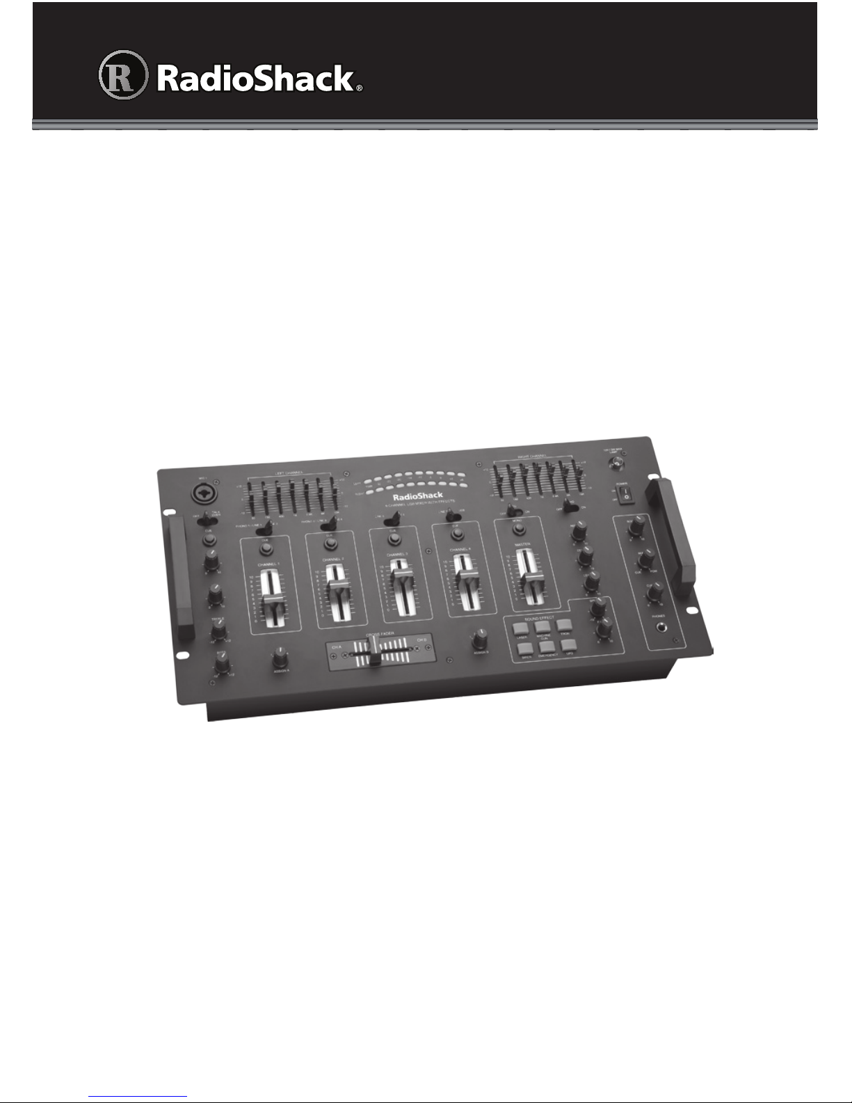
Thank you for purchasing your Stereo 4-Channel Mixer with Sound Effects from
RadioShack. Please read this user’s guide before installing, setting up, and using
your new Mixer.
Stereo • 4-Channel
Mixer with Sound Effects
Page 2

2
Contents
Contents
What’s Included ..................................................................................................3
IMPORTANT SAFETY INSTRUCTIONS .............................................................. 4
Setup ................................................................................................................10
Connecting Outputs .................................................................................................... 10
Connecting Inputs ....................................................................................................... 11
Connecting Microphones ............................................................................................ 12
Connecting Power ....................................................................................................... 12
Connecting a Lamp ..................................................................................................... 13
Connecting Headphones ............................................................................................13
Using Your Mixer .............................................................................................. 14
Presetting Input Signal Levels ..................................................................................... 14
Presetting Audio Input Sources ..................................................................................15
Presetting Microphone(s) ............................................................................................ 15
Checking the Sound ....................................................................................................16
Mixing Your Inputs ....................................................................................................... 16
Playing One Input Source ....................................................................................... 16
Monitoring a Second Input Source .........................................................................17
Switching to a Second Input Source .......................................................................17
Using Microphone(s) ...................................................................................................18
TREBLE and BASS Controls .................................................................................... 18
TALKOVER .............................................................................................................. 18
Using the Seven Band Equalizer .................................................................................19
Using ECHO Effects ....................................................................................................19
Adjust Echo Delay, Repeat, and Level .................................................................... 19
Using Sound Effects .................................................................................................... 20
Using Booth Level Control .......................................................................................... 20
Monitoring (Cuing) Inputs ........................................................................................... 20
Using the USB Port ...................................................................................................... 21
Input ........................................................................................................................21
Record ..................................................................................................................... 21
Additional Information .....................................................................................21
Replacing the Fuse ......................................................................................................21
Service and Repair .......................................................................................................21
Troubleshooting .......................................................................................................... 22
Specifications............................................................................................................... 22
FCC Information ..........................................................................................................23
Page 3
3
CAUTION
RISK OF ELECTRIC SHOCK
DO NOT OPEN
This symbol is intended to inform you that important
operating and maintenance instructions are included in the
literature accompanying this product.
This symbol is intended to alert you to the presence of uninsulated dangerous voltage within the product’s enclosure
that might be of sufficient magnitude to constitute a risk of
electric shock. Do not open the product’s case.
CAUTION: TO REDUCE THE RISK OF ELECTRIC SHOCK, DO NOT
REMOVE THE COVER OR BACK. NO USER-SERVICEABLE PARTS
INSIDE. REFER SERVICING TO QUALIFIED PERSONNEL.
WARNING: To reduce the risk of fire or shock hazard, do not expose
this product to rain or moisture.
What’s Included
• Stereo 4-Channel Mixer with Sound Effects
• User’s Guide
Page 4

4
IMPORTANT SAFETY INSTRUCTIONS
1. Read all safety and operating instructions before the appliance is operated.
2. Keep all safety and operating instructions for future reference.
3. Follow all warnings on the appliance and in the operating instructions.
4. Unplug this appliance from the wall outlet before cleaning. Use only a damp
cloth for cleaning. Do not use liquid or aerosol cleaners.
5.
Do not use this appliance near water (for example, near a bathtub, washbowl,
kitchen sink, or laundry tub; in a wet basement; or near a swimming pool).
6.
Do not place this appliance on an unstable cart, stand, tripod, bracket, or table.
The appliance may fall, causing serious injury to a child or adult, and serious
damage to the appliance. Use only with a cart, stand, tripod, bracket, or table
recommended by the manufacturer or sold with the appliance. Follow the
manufacturer’s instructions for mounting, and use a recommended mounting
accessory.
7.
Slots and openings in the cabinet provide ventilation, ensure reliable operation,
and protect from overheating. Do not block or cover these openings, and do
not place the appliance on a bed, sofa, rug, or other similar surface. Do not
place the appliance in a built-in installation such as a bookcase or rack unless it
provides proper ventilation as specified by the manufacturer.
8.
Keep appliance away from heat sources such as radiators, heat registers,
stoves, or other appliances (including amplifiers) that produce heat.
9.
Operate this appliance using only the power source indicated on its marking
label. If you are not sure of your home’s power type, consult your appliance
dealer or local power company.
10.
This appliance is equipped with a polarized power cord plug (a plug having
one blade wider than the other). This plug will fit in the power outlet only one
way. This is a safety feature. If you cannot insert the plug fully into the outlet, try
reversing the plug. If the plug still doesn’t fit, contact your electrician to replace
your obsolete outlet. Do not defeat the safety purpose of the polarized plug.
11.
Route power-supply cords so they are not likely to be walked on or pinched by
items placed on or against them, paying particular attention to cords at plugs,
convenience receptacles, and the point where they exit from the appliance.
12. Clean only as recommended by the manufacturer.
13. An outside antenna system should not be located in the vicinity of overhead
power lines or other electric light or power circuits, or where it can fall into such
power lines or circuits. When installing an outside antenna system, extreme
care should be taken to keep from touching such power lines or circuits as
contact with them might be fatal.
14. Unplug the power cord from the outlet when you know that you will not be
using the appliance for a long period of time.
15. Do not overload wall outlets, extension cords, or integral convenience
receptacles, as this can result in a risk of fire or electric shock.
Page 5

5
16. Never push objects of any kind into this appliance through openings, as they
may touch dangerous voltage points or short out parts that could result in a fire
or electric shock. Never spill liquid of any kind on the appliance.
17.
Move appliance and cart combinations with care. Quick stops, excessive
force, and uneven surfaces may cause the appliance and cart combination to
overturn.
18. Unplug this appliance from the wall outlet and refer servicing to a qualified
service personnel under the following conditions:
• When the power-supply cord or plug is damaged.
• If liquid has been spilled or objects have fallen into the appliance.
• If the appliance has been exposed to rain or water.
• If the appliance does not operate normally by following the operating
instructions. Adjust only those controls that are covered by the operating
instructions, as an improper adjustment of other controls may result in
damage and will often require extensive work by a qualified technician to
restore the appliance to normal operation.
•
If the appliance has been dropped or damaged in any way.
• When the appliance exhibits a distinct change in performance.
19. Do not attempt to service this appliance yourself, as opening or removing
covers may expose you to dangerous voltage or other hazards. Refer all
servicing to qualified service personnel.
20. When replacement parts are required, be sure the service technician has
used replacement parts specified by the manufacturer or have the same
characteristics as the original part. Unauthorized substitutions may result in fire,
electric shock, or other hazards.
21. Upon completion of any service or repairs to this appliance, ask the service
technician to perform safety checks to determine that the appliance is in proper
operating condition.
22.
For added protection for this product during a lightning storm, unplug it from
the wall outlet. This will prevent damage to the product due to lightning and
power line surges.
23.
Only use attachments recommended by the product manufacturer.
24. The product should be mounted to a wall or ceiling only as recommended by
the manufacturer.
25.
Do not overload wall outlets, extension cords, or integral convenience
receptacles, as this can result in a risk of fire or electric shock.
Page 6
6
LEFT CHANNEL / EQ
Cut or boost channel frequencies
by ± 12dB.
RIGHT CHANNEL / EQ
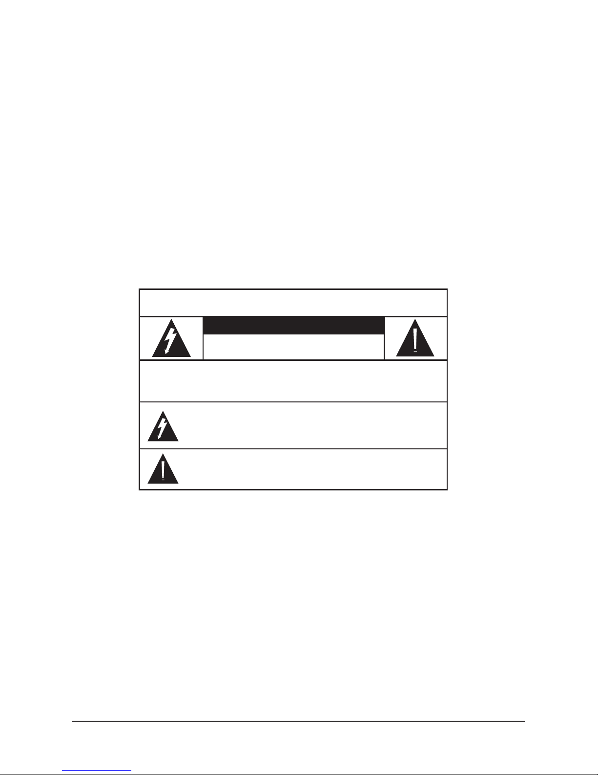
MIC 1 Combo Input Jack
Connect a balanced or
unbalanced low impedance
microphone with XLR-type or ¼
in. (6.35 mm) plug.
MIC TALKOVER ON/OFF
MIC CUE
Monitor and prepare for mixing
when wearing headphones.
MIC 1/MIC 2 Level Controls
MIC TREBLE
MIC BASS
CHANNELS 1–4
Select the input source and adjust the
volume of each channel.
Channel CUE Buttons
Select a channel to monitor and prepare
for mixing when wearing headphones.
MONO
Set the sound output
to stereo or monaural.
MASTER
Control the mixer’s
overall volume level.
LED Meters
Page 7

7
BOOTH
Control the mixer’s booth
volume level.
CUE/MIX/PGM
Balance output volume with
the input being prepared
for mixing when wearing
headphones.
CUE
Adjust the headphones
volume.
PHONES
Echo Controls
Compensate for environmental
conditions or adjust for
personal preference.
RIGHT CHANNEL / EQ
SOUND EFFECT
SPEED
Control the pitch of the selected effect.
F/X
Control the level of the selected effect.
CROSS FADER
Select an input source for
Channel A and Channel B and
mix the sound output between
the two sources.
LED Meters
Page 8
8
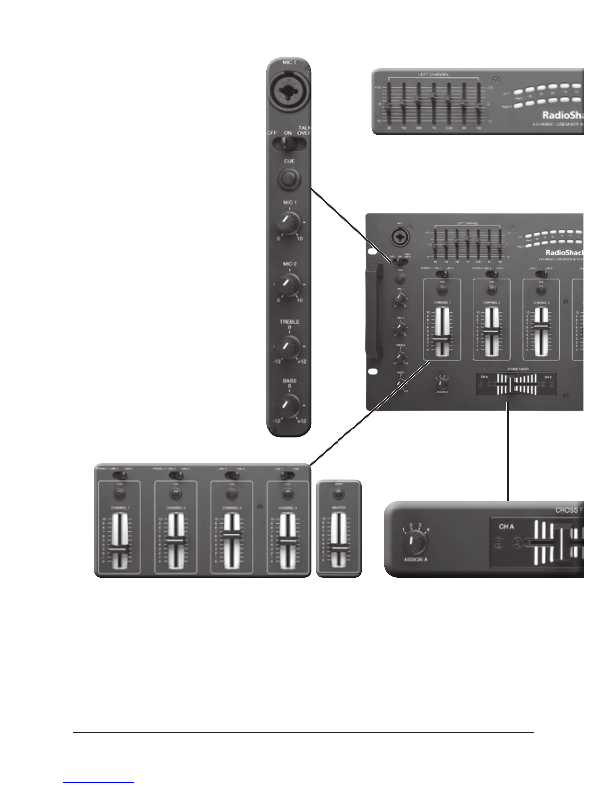
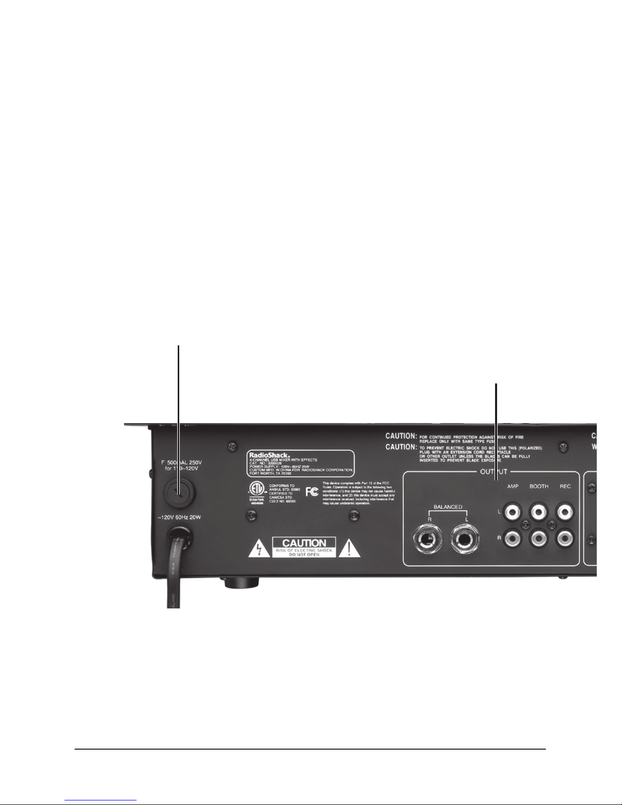
Output Connections
BALANCED
Connect your amplifier or receiver using a
balanced ¼ in. (6.35 mm) audio cable (not
supplied).
AMP
Connect the mixer’s output to your receiver or
amplifier.
BOOTH
Connect to another receiver or amplifier, or
connect to powered speakers.
REC
Connect to the line input of your recording
device so you can record sound from the mixer.
Fuse
Page 9

9
Input Connections
CH 1 (LINE 1/LINE 2), CH 2 (LINE 3/LINE 4), CH 3 (LINE 5/
LINE 6) CH 4 (LINE 7/USB)
PHONO 1/LINE 1 and PHONO 2/LINE 3
In PHONO 1 and PHONO 2 settings, connect low-level
audio sources (such as turntables). In LINE 1 and LINE 3
settings, connect high-level audio sources.
INPUT SELECT
Set switches based on what is plugged into PHONO 1/LINE
1 and PHONO 2/LINE 3 input jacks.
MIC 2
Connect a balanced
or unbalanced
low-impedance
microphone with a
¼ in. (6.35 mm) plug.
GROUND
Connect the
ground wire from a
magnetic cartridge
turntable.
Page 10

10
Setup
Setup
w Caution: A sudden high output from the mixer could damage your hearing
or damage the audio devices connected your mixer. Before connecting to AC
power, turn off your mixer and all audio devices connected to your mixer.
Connecting Outputs
To play the mixer’s output signal through your sound system, connect one end
of an RCA audio cable (not included) to the mixer’s AMP OUTPUT L (white)
and R (red) jacks. Then connect the other end to your receiver/amplifier’s L and
R input jacks, matching L to L and R to R.
If your amplifier or receiver is not equipped with RCA jacks, connect one end
of a ¼ in. (6.35 mm) audio cable to the mixer’s BALANCE OUTPUT L/R jacks.
Then connect the other end to your amplifier or receiver’s input jack.
n Note: Do not connect the ¼ in. (6.35 mm) audio cable and RCA audio cable
simultaneously.
To record the mixer’s output signal, connect one end of an audio patch cord
(not supplied) to the mixer’s REC OUTPUT L (white) and R (red) jacks, then
connect the other end to your recording device’s L and R line input jacks,
matching L to L and R to R.
AMP OUTPUT L/R
BALANCED OUTPUT L/R
REC OUTPUT L/R
Page 11

11
Setup
To monitor the mixer output on a second set of speakers, connect one end of
an audio patch cord (not supplied) to the mixer’s BOOTH OUTPUT L (white)
and R (red) jacks. Then connect the other end to your secondary amplifier’s L
and R input jacks, matching L to L and R to R.
Connecting Inputs
You can connect up to eight audio input sources (such as a tuner, cassette
deck, CD player, or VCR) to the input jacks on the back of the mixer.
w Caution: Do not connect an audio source with a line-level to the low-level
PHONO 1 or PHONO 2 audio input jacks.
1. Connect the line-level outputs from up to seven audio sources to the LINE
(1–7) input jacks, matching left to left, and right to right.
n Note: PHONO 1 and LINE 1 (as well as PHONO 2 and LINE 3) use the
same jack. When connecting the line-level output audio sources, slide INPUT
SELECT to LINE 1 and LINE 3.
2. Connect the low-level outputs from up to two audio sources (such as
turntables) to the PHONO 1 and PHONO 2 input jacks.
n Note:
• If you connect magnetic-cartridge turntables, connect their ground wires
(usually black or green) to GROUND.
• To use PHONO 1 and PHONO 2 input jacks, slide INPUT SELECT to
PHONO 1 and PHONO 2.
BOOTH OUTPUT L/R
PHONO 1 and
PHONO 2
GROUND
Page 12

12
Setup
Connecting Microphones
You can connect two microphones (not supplied) to the mixer.
Connect a microphone with either an XLR plug or a ¼ in. (6.35 mm) plug to
MIC 1 on the top panel.
Connect a microphone with a ¼ in. (6.35 mm) plug to MIC 2 on the lower right
corner of the back panel.
Connecting Power
Connect the mixer’s power cord to a standard AC outlet.
w Caution: The power cord has a polarized plug that only fits one way into
a standard AC outlet. If the plug does not fit, turn it over so it fits properly. Do
not force it.
MIC 1 Jack
MIC 2 Jack
Page 13

13
Setup
Connecting a Lamp
Connect a 12V DC/3W BNC lamp (not supplied) to the 12V/3W MAX LAMP
socket so you can see the control panel in dark or low-light conditions.
Connecting Headphones
To listen in privacy or monitor the audio source inputs so you can locate an
exact passage or section before mixing it, connect a pair of stereo headphones
(not supplied) with a ¼ in. (6.35 mm) plug to the PHONES jack.
Do not listen at extremely high volume levels. Extended, high-volume listening
can lead to permanent hearing loss. To protect your hearing when using
headphones, always follow these guidelines to set the listening volume:
•
Set CUE (headphones volume) to minimum before putting on your
headphones.
•
After you put on the headphones, adjust CUE to a comfortable listening
level. Do not increase the CUE setting. Over time, your ears adapt to the
volume level.
12V/3W MAX LAMP
PHONES Jack
CUE
Page 14

14
Operation
Using Your Mixer
1. Set the volume level on the output devices (receiver, amplifier, and so forth) to
minimum and turn them on.
2.
Press POWER to turn on the mixer.
3.
Turn on the audio input sources you want to mix.
4. Using the mixer requires two basic operations:
• To preset the input signal levels, see “Presetting Input Signal Levels” on
page 14, and ““Presetting Audio Input Sources” on page 15.
• To mix audio input sources, see “Mixing Your Inputs” on page 16.
5. When finished, turn off all connected audio sources, and press POWER to turn
off the mixer.
Presetting Input Signal Levels
To avoid overdriving a channel or prematurely mixing an audio input source,
adjust your mixer to these settings:
•
Set CHANNELS 1–4 to 0.
•
Set CUE, MIC 1–2, TREBLE, and BASS level controls, and BOOTH to 0, and
set CUE/MIX/PGM to MIX.
•
Set MASTER level control to 5.
•
Press MASTER MONO (in) for monaural output. Press again (out) for stereo
output.
MIC TREBLE
MIC BASS
CHANNEL Volume Controls
MASTER
CUE
MIC 2 level
MIC 1 level
BOOTH
Page 15

15
Operation
Presetting Audio Input Sources
Before mixing your audio sources (devices connected to PHONO 1/LINE 1,
LINE 2, PHONO 2/LINE 3, LINE 4–7, and USB port), you must set their input
signal levels to each channel input (CHANNELS 1–4). You do not have to mix
every connected input source.
1. Above each CHANNEL Volume Control, there is a channel selector. Set the
channel selector to the desired input source (PHONO 1/LINE 1/LINE 2,
PHONO 2/LINE 3/LINE 4, LINE 5/LINE 6, LINE 7/USB).
2.
Play the selected input source.
3. Adjust the volume on your headphones or receiver to a comfortable listening
level.
4.
Slowly slide up the CHANNEL volume control until you get a reading of up to 0
on the mixer’s LED meters.
5.
Stop playback of the selected input source.
6. Repeat these steps to preset PHONO 1/LINE 1 and LINE 2 to CHANNEL
1; PHONO 2/LINE 3 and LINE 4 to CHANNEL 2; LINE 5 and LINE 6 to
CHANNEL 3; LINE 7 and USB to CHANNEL 4.
n Note:
• Write down the channel volume control’s setting for each audio source, so
each time you want to mix that source, you can adjust its volume to that
setting.
• If you had to set the channel volume to maximum to get a reading of 0 or
less on the LED meter, then slide channel volume down to about 8 and
slide MASTER up until you get a reading of 0 on both LED meters.
Presetting Microphone(s)
1. If your microphone has an ON/OFF control, turn it ON. Otherwise, rotate MIC
1/2 level controls to 0.
2.
Set TALKOVER/ON/OFF to ON.
3.
While talking, adjust MIC 1/2 level controls until you get a signal reading of up
to 0 on both LED meters.
4.
Set TALKOVER/ON/OFF to OFF.
n Note:
• Write down the MIC 1 level or MIC 2 level settings. When you want to mix
with the microphone, you can adjust it to this setting.
• If you have to adjust MASTER, this affects the level of the previously set
input sources. You must readjust those sources accordingly.
Page 16

16
Operation
Checking the Sound
1. Select an input source to play.
2. Adjust its volume (CHANNEL volume control) to its preset signal level (see
“Presetting Input Signal Levels” on page 14). The mixer’s LED meters should read 0
dB or less.
3.
Adjust your receiver/amplifier’s volume to an appropriate level for the location.
4. Adjust the LEFT CHANNEL and RIGHT CHANNEL frequency controls to your
preference (see “Using the Seven Band Equalizer” on page 19). If this causes the LED
meters to exceed 0 dB, slide MASTER down until their readings return to 0 dB.
Adjust your output device’s volume accordingly.
Mixing Your Inputs
You can select any two of your connected audio sources and mix them so one
or both play through your sound system. Mixing consists of three parts:
•
Playing one input source
• Monitoring a second input source
• Switching to a second input source
Playing One Input Source
1. Set ASSIGN A to the desired audio source (1, 2, 3, and 4 correspond to
CHANNELS 1–4).
2.
Slide the CROSS FADER all the way to CH A.
3. Set PHONO 1/LINE 1, LINE 2, PHONO 2/LINE 3, LINE 4–7 and USB to the
input source you are going to play first.
4.
Adjust the input source’s volume to the desired level.
5. Play the source.
RIGHT
CHANNEL
LEFT
CHANNEL
MASTER
Page 17

17
Operation
Monitoring a Second Input Source
Monitoring a second input source requires listening to an input source, finding
the desired audio section you want to mix, and adjusting its sound level to
match the volume of the first input source (ASSIGN A).
1. Connect and put on your headphones. You can listen to one source through
the headphones while the other source plays over the sound system.
2. Set ASSIGN B to the second input source.
3. Press CUE for the second input (above the CHANNEL control).
4. Select PHONO 1/LINE 1, LINE 2, PHONO 2/LINE 3, LINE 4, LINE 5, LINE 6,
LINE 7 or USB, depending on the location of the second input source.
5. Play the second input source.
6. Adjust the second input source’s volume to its preset signal level. If using
headphones, adjust the CUE level (headphones volume) to a comfortable
listening level.
7. When you reach the desired section of music to mix, stop or pause the second
input source.
Switching to a Second Input Source
1. Play the second input source.
2. When you are ready to hear it play on your sound system, slide the CROSS
FADER from CH A to CH B.
3. Slide the CROSS FADER to the left (CH A) to fade in ASSIGN A (first input
source) and fade out ASSIGN B (second input source). Slide the CROSS
FADER to the right (CH B) to fade in ASSIGN B and fade out ASSIGN A. Slide
the CROSS FADER to the center to equally mix the two.
n Note: Do not slide the CROSS FADER to the center when monitoring
a channel while another is playing. Instead, slide the CROSS FADER to the
channel you are not monitoring. For example, to monitor channel 1 (ASSIGN
A) while channel 2 (ASSIGN B) is playing, slide CROSS FADER to CH A.
CROSS FADERASSIGN A
ASSIGN B
3200026_UG_EN_041912.indd 17 5/15/2012 10:19:14 AM
Page 18

18
Operation
Using Microphone(s)
To mix the microphone connected to the MIC 1 or MIC 2 jack with other audio
input sources, rotate MIC 1 or MIC 2 to increase or decrease the microphone
volume. Set MIC 1 or MIC 2 to 0 when you are not using the microphone.
TREBLE and BASS Controls
Your mixer has a set of TREBLE and BASS controls to tailor the frequency
sounds for each microphone.
1. For regular sound, leave MIC TREBLE and MIC BASS set to 0.
2.
Rotate MIC TREBLE toward +12 to increase high frequency sounds, or toward
-12 to decrease high frequency sounds.
3. Rotate MIC BASS toward +12 to increase low frequency sounds, or toward -12
to decrease low frequency sounds.
TALKOVER
When you are not using your microphone, set TALKOVER/ON/OFF to OFF.
The microphone’s input is turned off and all other audio input sources are
unaffected.
1. To use your microphone, set TALKOVER/ON/OFF to ON. The microphone
sound is mixed equally with the other audio input sources.
2. Set TALKOVER/ON/OFF to TALKOVER so the microphone’s sound is louder
than the other audio input sources.
TREBLE
BASS
TALKOVER
ON/OFF
Page 19

19
Operation
Using the Seven Band Equalizer
The seven band equalizer controls, LEFT CHANNEL and RIGHT CHANNEL,
further tailor the frequency for CHANNELS 1–4 to match your acoustic
surroundings or to suit your personal preference.
1. To activate the equalizer, slide EQ ON/OFF to ON.
2.
Set the LEFT CHANNEL and RIGHT CHANNEL controls for a selected
frequency to +12dB to boost, or toward -12dB to cut the frequency’s sound.
To provide smooth frequency control, the equalizer’s controls must overlap
slightly. Thus, the 1K control has a light effect on the range of frequencies
covered by the 400Hz and 2.4K controls.
Using ECHO Effects
The mixer provides an echo effect and lets you adjust each delay, number of
echo repeats, and the echo’s volume. The echo is applied to the sound after all
of the inputs are mixed.
Slide ECHO ON/OFF to ON to turn on the echo effect. To turn it off, slide
ECHO ON/OFF to OFF.
Adjust Echo Delay, Repeat, and Level
To adjust the time interval between echoes, rotate ECHO DELAY. Set ECHO
DELAY to 0 for minimum delay, and to 10 for maximum time delay.
To adjust the length of time a tone is repeated (reverberation), rotate ECHO
REPEAT. Set ECHO REPEAT to 10 for the longest reverberation and to 0 for
the shortest.
To adjust the echo output level, rotate ECHO LEVEL. Rotate ECHO LEVEL
toward 10 to increase the echo level, and toward 0 to decrease it.
ECHO ON/OFF
ECHO REPEAT
ECHO DELAY
ECHO LEVEL
Page 20

20
Operation
Using Sound Effects
Your mixer provides six preprogrammed sound effects: TRON, UFO, MACHINE
GUN, EMERGENCY, LASER, and SIREN.
To play a sound effect, repeatedly press or hold down the desired SOUND
EFFECT button.
To control sound effect pitch, rotate SOUND EFFECT SPEED.
To control sound effect level, rotate SOUND EFFECT F/X.
Using Booth Level Control
If you set up remote speakers or DJ booth monitors, rotate BOOTH control to
control the mixer’s overall booth volume level.
Monitoring (Cuing) Inputs
1. Press in the CUE button for the input source you wish to monitor (MIC,
CHANNEL 1, CHANNEL 2, CHANNEL 3, and CHANNEL 4).
2.
Rotate CUE located above the PHONES jack to set a comfortable listening
level for the headphones.
3.
To listen to the CUE material, rotate CUE/MIX/PGM to CUE.
To listen to the active program, rotate CUE/MIX/PGM to PGM.
To listen to both simultaneously, set CUE/MIX/PGM to MIX.
Using the USB Port
You can input audio from a PC or Mac® to the mixer, or record audio to a PC or
MAC through the USB port.
SOUND EFFECT SPEED
SOUND EFFECT F/X
Page 21

21
Additional Info
Input
1. Set the channel selector to USB.
2.
Connect the PC or Mac to the USB port with a standard high-speed USB cable
(not supplied). Then play the audio through the computer’s audio player.
Record
1. On the mixer, mix your inputs.
2. Connect the PC or Mac to the USB port with a standard high-speed USB cable
(not supplied). Record the audio to the PC or Mac.
Additional Information
Replacing the Fuse
Your mixer requires a 250 Volt, 0.5 Amp fuse to protect it from power surges
and short circuits. If the mixer suddenly turns off or will not turn on, the fuse
could be blown. Replace the fuse with a 250 Volt, 0.5 Amp, fast-blow, 1¼ x ¼
inch (32 mm x 6.35 mm) fuse (not supplied, available at your local RadioShack
store or at www.radioshack.com).
n Note: Do not use a fuse with a rating other than that specified here. Doing
so might damage your mixer.
1. Unplug the mixer from the AC outlet.
2. Use a Phillips screwdriver to remove the fuse compartment cap from the mixer.
3. Remove the old fuse and replace it with an identical fuse.
4. Replace the fuse compartment cap.
Service and Repair
If your mixer is not performing as it should, take it to your local RadioShack
store for assistance. Modifying or tampering with the mixer‘s internal
components can cause a malfunction and might invalidate its warranty.
Fuse Compartment
Cap
Page 22

22
Additional Info
Troubleshooting
Problem Solution
The mixer won’t turn on. Check the AC power connection and make sure
the AC outlet is “live.”
Check the power connections to the rest of system
(amplifier/receiver, input sources, and so on).
Check the fuse, and replace it if necessary.
There no signal from my input
sources.
Check the control settings of the mixer and the
input sources.
Ensure the proper connection between the mixer
and input sources.
Make sure TALKOVER/ON/OFF is not set to
TALKOVER.
Make sure the input source is turned on.
I hear a humming noise from
the PHONO source.
Make sure the PHONO 1 or PHONO 2 source’s
ground wire is connected to the mixer’s GROUND
terminal.
I hear a humming noise from
another (non-PHONO) input
source.
Make sure there are no low-level inputs connected to
the mixer’s line input jacks.
I hear microphone feedback
(squealing).
Move the microphone farther away from the
output speakers or use a directional microphone.
Specications
Input Sensitivity/Impedance
MIC 1 (Combo jack) ..............................................1.5 mV, 600 ohms, Balanced/Unbalanced
MIC 2 (PHONE jack)
.............................................1.5 mV, 600 ohms, Balanced/Unbalanced
PHONO 1, PHONO 2
.....................................................................................3 mV/50 kOhms
LINE 1, LINE 2, LINE 3, LINE 4, LINE 5, LINE 6, LINE 7
...........................150 mV/27 kOhms
USB Port .................................................................................................................... USB 1.1
Output Level
Main Out ..........................................................................................................1.2V/10 kOhms
Record
.........................................................................................................150 mV/10 kOhms
Frequency Response
......................................................................................20–20K Hz±3dB
S/N Ratio (for 1 kHz)
MIC ....................................................................................................................................60dB
PHONO
............................................................................................................................. 70dB
LINE
...................................................................................................................................80dB
Distortion
MIC ...................................................................................................................................0.20%
PHONO
............................................................................................................................0.08%
LINE
..................................................................................................................................0.05%
Page 23

23
Additional Info
Tone Control (MIC)
TREBLE ........................................................................................................................... ±12dB
BASS
............................................................................................................................... ±12dB
Equalizer Control
Control Frequencies .................................................... 60, 150, 400, 1k, 2.4k, 6k, and 15k Hz
Boost/Cut Range
......................................................................................±12dB from Center
Talkover Attenuation
.......................................................................................................-16dB
Power Source
...........................................................................................AC 120V, 60Hz, 20W
Dimensions (H × W × D)
............................................. 9.5 × 19 × 4 in. (240 × 482 × 102mm)
Weight
............................................................................................................... 9.68 lb (4.4 kg)
Fuse
............................................................250V, 0.5A, fast-blow, 1¼ x ¼ in. (32 × 6.35 mm)
Specifications are subject to change and improvement without notice. Actual product may vary
from the images found in this document.
FCC Information
This equipment has been tested and found to comply with the limits for a Class B digital device,
pursuant to Part 15 of the FCC Rules. These limits are designed to provide reasonable protection
against harmful interference in a residential installation. This equipment generates, uses, and can
radiate radio frequency energy and, if not installed and used in accordance with the instructions, may
cause harmful interference to radio communications. However, there is no guarantee that interference
will not occur in a particular installation. If this equipment does cause harmful interference to radio
or television reception, which can be determined by turning the equipment off and on, the user is
encouraged to try to correct the interference by one or more of the following measures:
•Reorientorrelocatethereceivingantenna.
•Increasetheseparationbetweentheequipmentandreceiver.
•Connecttheequipmentintoanoutletonacircuitdifferentfromthattowhichthereceiveris
connected.
•ConsultyourlocalRadioShack store or an experienced radio/TV technician for help.
If you cannot eliminate the interference, the FCC requires that you stop using your equipment.
Changes or modifications not expressly approved by RadioShack may cause interference and void
the user’s authority to operate the equipment.
This device complies with Part 15 of the FCC rules. Operation is subject to the following two
conditions: (1) This device may not cause harmful interference, and (2) This device must accept any
interference received, including interference that may cause undesired operation.
Limited Warranty
RadioShack warrants this product against defects in materials and workmanship under normal use
by the original purchaser for one (1) year after the date of purchase from a RadioShack-owned store
or an authorized RadioShack franchisee or dealer. RADIOSHACK MAKES NO OTHER EXPRESS
WARRANTIES.
Product Stereo 4-Channel Mixer with
Sound Effects
Model 3200026
Responsible
Party
RadioShack
300 RadioShack Circle
Fort Worth, TX 76102
Phone 817-415-3200
Page 24

Printed
in China
04A12
3200026
©2012. RadioShack Corporation.
All rights reserved. RadioShack and RadioShack.com are
trademarks used by RadioShack Corporation.
Protect the environment by recycling your used electronics. Go to
E-CyclingCentral.com to find an electronic recycling center near you.
Complies with the European Union’s “Restriction of Hazardous Substances
Directive,” which protects the environment by restricting specific hazardous
materials and products.
This warranty does not cover: (a) damage or failure caused by or attributable to abuse, misuse, failure
to follow instructions, improper installation or maintenance, alteration, accident, Acts of God (such
as floods or lightning), or excess voltage or current; (b) improper or incorrectly performed repairs
by persons who are not a RadioShack Authorized Service Facility; (c) consumables such as fuses or
batteries; (d) ordinary wear and tear or cosmetic damage; (e) transportation, shipping or insurance costs;
(f) costs of product removal, installation, set-up service, adjustment or reinstallation; and (g) claims by
persons other than the original purchaser.
Should a problem occur that is covered by this warranty, take the product and the RadioShack sales
receipt as proof of purchase date to any RadioShack store in the U.S. RadioShack will, at its option,
unless otherwise provided by law: (a) repair the product without charge for parts and labor; (b) replace
the product with the same or a comparable product; or (c) refund the purchase price. All replaced parts
and products, and products on which a refund is made, become the property of RadioShack. New or
reconditioned parts and products may be used in the performance of warranty service. Repaired or
replaced parts and products are warranted for the remainder of the original warranty period. You will be
charged for repair or replacement of the product made after the expiration of the warranty period.
RADIOSHACK EXPRESSLY DISCLAIMS ALL WARRANTIES AND CONDITIONS NOT STATED IN THIS
LIMITED WARRANTY. ANY IMPLIED WARRANTIES THAT MAY BE IMPOSED BY LAW, INCLUDING
THE IMPLIED WARRANTY OF MERCHANTABILITY AND, IF APPLICABLE, THE IMPLIED WARRANTY
OF FITNESS FOR A PARTICULAR PURPOSE, SHALL EXPIRE ON THE EXPIRATION OF THE STATED
WARRANTY PERIOD.
EXCEPT AS DESCRIBED ABOVE, RADIOSHACK SHALL HAVE NO LIABILITY OR RESPONSIBILITY TO
THE PURCHASER OF THE PRODUCT OR ANY OTHER PERSON OR ENTITY WITH RESPECT TO ANY
LIABILITY, LOSS OR DAMAGE CAUSED DIRECTLY OR INDIRECTLY BY USE OR PERFORMANCE OF
THE PRODUCT OR ARISING OUT OF ANY BREACH OF THIS WARRANTY, INCLUDING, BUT NOT
LIMITED TO, ANY DAMAGES RESULTING FROM INCONVENIENCE AND ANY LOSS OF TIME, DATA,
PROPERTY, REVENUE, OR PROFIT AND ANY INDIRECT, SPECIAL, INCIDENTAL, OR CONSEQUENTIAL
DAMAGES, EVEN IF RADIOSHACK HAS BEEN ADVISED OF THE POSSIBILITY OF SUCH DAMAGES.
Some states do not allow limitations on how long an implied warranty lasts or the exclusion or limitation
of incidental or consequential damages, so the above limitations or exclusions may not apply to you.
This warranty gives you specific legal rights, and you may also have other rights which vary from state to
state. You may contact RadioShack at:
RadioShack Customer Relations
300 RadioShack Circle, Fort Worth, TX 76102 04/08
www.RadioShack.com
Mac is a trademark of Apple, Inc., registered in the U.S and other countries.
 Loading...