

Page 1

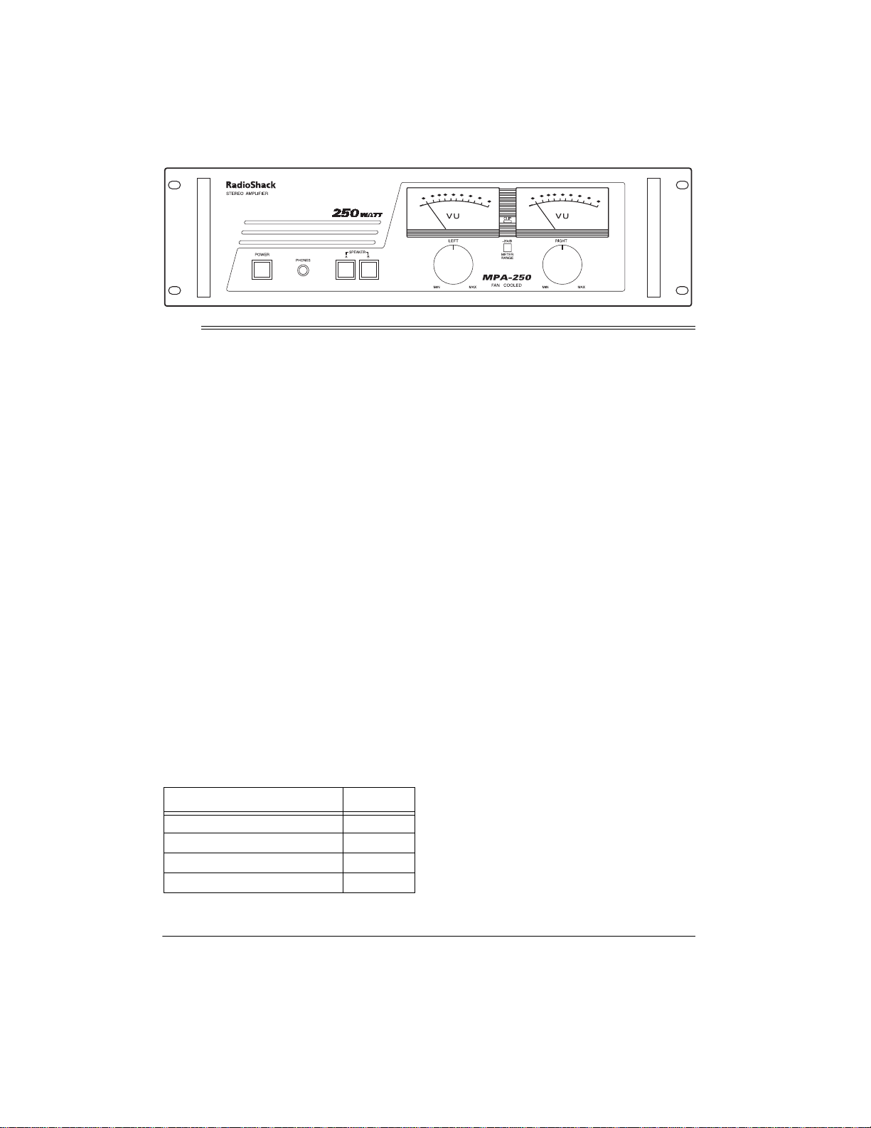
250-Watt Stereo PA Amplifier
Owner’s Manual
Please read before using this equipment.
Page 2

ˆ
Contents
Contents .................................................................................................................................. 2
Features .................................................................................................................................. 3
Preparation ............................................................................................................................. 4
Presetting the Controls ...................................................................................................... 4
Presetting Audio Input Devices .................................................................................. 4
Presetting the Amplifier .............................................................................................. 4
Mounting the Amplifier ...................................................................................................... 4
Placing the Speakers ........................................................................................................ 4
Connections ............................................................................................................................ 5
Connecting an Input Source .............................................................................................. 5
Unbridged Connection ............................................................................................... 5
Bridged Connection ................................................................................................... 5
Grounding the Input Source .............................................................................................. 6
Connecting Speakers ........................................................................................................ 6
Preparing the Speaker Wires ..................................................................................... 6
Unbridged Connection ............................................................................................... 6
Bridged Connection ................................................................................................... 7
Using the Switched AC Outlet ........................................................................................... 7
Connecting Power ............................................................................................................. 7
Using Your Amplifier .............................................................................................................. 8
Using the Meters/METER RANGE .................................................................................... 8
CLIP Indicator ................................ ...................................................................... ............. 8
Using SPEAKER A/B ........................................................................................................ 8
Monitoring the Sound Sources .......................................................................................... 8
Listening Safely ......................................................................................................... 9
Care ......................................................................................................................................... 9
Replacing the Fuse .............................................................................. ............................. 9
The FCC Wants You to Know .............................................................................................. 10
Specifications ....................................................................................................................... 11
©
1998, 2000 Tandy Corporation.
RadioShack is a registered trademark used by Tandy Corporation.
2
All Rights Reserved.
Contents
Page 3
ˆ
Features
Your Public Address Amplifier gives you the
versatility and power you need in a professional sound system. Its wide frequency response easily handles amplification of voice
and music. Use it in meeting halls and auditoriums, at sports events, in schools, and in
the office for paging systems — anywhere
you need to deliver special announcements
with excellent sound.
The amplifier (if bridged) produces up to 350
watts of clean, powerful sound with minimum
distortion.
Your amplifier includes these features:
10–50000 Hz Frequency Response
Built-In Cooling Fan
amplifier by reducing its internal temperature.
Two Mounting Options
the amplifier in a standard-sized audio equipment rack or on a desk, shelf, or table.
2 Lighted VU Meters
fier’s output for each channel in decibels.
Left and Right Output Level Gain Controls
— let you adjust the overall sound level on
the left and right channels.
Clipping Indicator
source signal overdrives the amplifier.
Phones Jack
phones so you can listen privately.
Bridging Capability
amplifier’s two channels and use the amplifier with only one channel, producing a total of
350 watts.
Meter Range Select Switch
trol the meter’s sensitivity.
— lets you connect head-
— helps protect the
— you can mount
— measure the ampli-
— lights if a sound
— you can combine the
— lets you con-
Input Jacks
audio input sources for music and special effects.
A/B SPEAKER
speakers you want to use with the amplifier.
STEREO/MONO
output type; stereo or mono (bridged).
Binding Post Terminals
connect wires directly to the amplifier.
Switched AC Outlet
devices by plugging them into the back of the
amplifier.
WARNING
shock hazard, do not expose this product
to rain or moisture.
CAUTION
ELECTRIC SHOCK, DO NOT REMOVE
COVER OR BACK. NO USER-SERVICEABLE PARTS INSIDE. REFER SERVICING
TO QUALIFIED PERSONNEL.
!
—let you connect a variety of
Switches
Switch
: To reduce the risk of fire or
CAUTION
RISK OF ELECTRIC SHOCK.
: TO REDUCE THE RISK OF
This symbol is intended to alert you to
the presence of uninsulated dangerous voltage within the product’s enclosure that might be of sufficient
magnitude to constitute a risk of electric shock. Do not open the product’s
case.
This symbol is intended to inform you
that important operating and maintenance instructions are included in the
literature accompanying this product.
— let you select the
— lets you select the
— let you easily
— lets you power other
DO NOT OPEN.
!
Features
3
Page 4
ˆ
Preparation
PRESETTING THE
CONTROLS
Before you begin making connections or using your amplifier, preset the audio input
source’s and the amplifier’s controls to avoid
overdriving a channel or producing sudden
unexpected loud sounds.
Warning:
set the audio input device’s and amplifier’s
controls as indicated in the following sections. After you turn on the amplifier or
change the program source, adjust the controls to a comfortable listening level.
Presetting Audio Input Devices
Always set the power control for an audio
mixer or preamplifier you connect to the amplifier to OFF.
Presetting the Amplifier
Set the amplifier’s controls as follows:
POWER
SPEAKER A/B
LEFT and RIGHT MIN
METER RANGE
To prevent possible hearing loss,
Control Setting
Out
Out
Out
MOUNTING THE AMPLIFIER
You can mount the amplifier in a standardsized audio equipment rack or on a desk,
shelf, or table. Before you use your amplifier,
be sure you place it in a location with adequate ventilation. Do not put it on thick carpeting (which can restrict air flow) or near a
heat source such as a heat vent or radiator
(which can cause it to overheat).
To mount the amplifier on a standard-sized
audio equipment rack, drive and tightly secure mounting screws (not supplied) through
the mounting holes.
PLACING THE SPEAKERS
Speaker placement depends on your room’s
size and arrangement. We recommend you
play a wide-range recording and experiment
with speaker placement until you find the locations that result in the best sound. For the
best results, point the speakers toward the
audience (especially if the speakers are far
apart) so the coverage areas overlap to prevent dead spots (areas not covered by the
speakers’ sound). Position the speakers
slightly above the level of the listeners’
heads (see “Connecting Speakers” on
Page 6).
4
Preparation
Page 5

The following drawings show recommended
speaker placements for typical, narrow, and
wide sound coverage.
Typical Coverage
ˆ
Connections
Wide Area CoverageNarrow Coverage
(two speakers)(single speaker)
CONNECTING AN INPUT
SOURCE
You can connect a component such as an
audio mixer or preamplifier to the inputs on
the back of your amplifier. Each input (la-
INPUT
beled
anced and unbalanced jack. You need a
shielded cable with a
phono plug to connect to an unbalanced jack
or a cable with a phono-type plug to connect
to a balanced jack. To prevent hum and other noise, use low-capacitance shielded cable. Your local RadioShack store carries a
wide selection of audio components, parts,
and cables.
Note:
If you are using the
you must connect an audio mixer or pre-amplifier to this amplifier.
Cautions:
• You can connect audio mixers or pream-
• Before you make any connections, be
plifiers to either the balanced or unbalanced jacks. Do not connect input
sources to both jacks at the same time.
POWER
sure
INPUT MONO
and
on the front of the amplifier
) has a bal-
1
/4-inch (6.35-mm)
MIC
level inputs,
is off and the AC power cord is not
plugged in.
Unbridged Connection
If you are connecting more than one speaker
on the same channel (unbridged connection), connect your audio mixer’s or preamplifier’s left and right output jacks to the
R
INPUT L
and
fier. Then, make sure
back of the amplifier is set to
jacks on the back of the ampli-
STEREO/MONO
STEREO
INPUT
on the
.
Bridged Connection
If you are connecting high-power speakers
that can handle a power output of 350 watts
(bridged connection), connect your audio
mixer’s or preamplifier’s output jack to the
PUT MONO
INPUT L
or
jack on the back of the
IN-
Connections
5
Page 6

amplifier. Then, make sure
STEREO/MONO
on the back of the amplifier is set to
MONO
speakers, use this table to determine the
wire length and choose the appropriate
.
gauge.
GROUNDING THE INPUT
SOURCE
To avoid a low frequency hum, connect your
audio mixer’s or preamplifier’s ground wire
GND
(usually black or green) to the
terminal
on the back of the amplifier.
CONNECTING SPEAKERS
You can connect one or more 4-, 8-, or 16ohm speakers to the amplifier. You can also
bridge the amplifier’s channels.
A
The amplifier has two channels:
you connect two pairs of speakers, follow
these guidelines:
• Speakers connected to the same chan-
A
or B) are part of a pair and must
nel (
be of the same impedance.
• Speakers connected to different chan-
A
or B) are not part of a pair and
nels (
can be different impedances.
Most speaker terminals are color-coded or
have a mark that indicates the terminal’s polarity. Usually, terminals with positive polarity
are red or have a plus symbol (+), and terminals with negative polarity are black or have
a minus symbol (–). Phasing is correct when
you connect + to + and – to –.
and B. If
Wire Length Wire Gauge
25 feet or less 18 gauge
Over 25 feet 16 gauge
To prepare the speaker wire, remove about 1
inch of insulation from the end of the speaker
wire you are connecting to the amplifier.
Then twist the exposed wire to secure all of
the wire strands.
Split strands
about 4”
Wire Strands
1"
Unbridged Connection
Use this connection if you are connecting
more than one speaker on the same channel
or if you do not have high-power speakers.
1. Connect the speaker
wires to the corresponding left and right
speaker’s positive (+)
and negative (–) terminals.
2. Connect the other end of the left and
right speaker’s positive (+) and negative
(–) wires to the amplifier’s correspond-
SPEAKERS LEFT
ing
and
SPEAKERS
Preparing the Speaker Wires
Use the shortest length of wire possible to
connect the speakers. After placing the
6
Connections
Page 7

RIGHT
terminals for each channel (as
shown here).
SPEAKERS RIGHT
here).
terminals (as shown
To connect the
speaker wires to
the amplifier, turn
the knob on the
terminal counterclockwise until it
stops, insert the bare wire inside the
space between the knob and the amplifier, then turn the knob clockwise until it
stops to secure it.
3. Make sure
REO
.
STEREO/MONO
is set to
STE-
Bridged Connection
Use this connection only if you have highpower speakers that can handle a power output of 350 watts.
Important:
connect any speaker wires to the black
SPEAKERS
1. Connect the speaker wires to the
2. Connect the other end of the speaker’s
For a bridged connection, do not
terminals.
speaker’s positive (+) and negative (–)
terminals.
positive (+) and negative (–) wires to the
amplifier’s red
SPEAKERS LEFT
and
Note:
SPEAKERS RIGHT (+)
on the
amplfier is used as a negative (–) terminal for a bridged connection.
3. Make sure
MONO
.
STEREO/MONO
is set to
USING THE SWITCHED AC
OUTLET
The amplifier’s switched AC outlet provides a
source of 120 V, 60 Hz power for audio
equipment you connect to it.
POWER
on the
amplifier turns both the amplifier and th e audio equipment connected to this outlet on or
off.
CONNECTING POWER
To connect the amplifier to power, plug the
attached power cord into a standard AC outlet.
Your amplifier’s fuse (located on the amplifier’s back panel) protects the amplifier from
voltage surges. If the amplifier does not work
when you press
POWER
is blown, see “Replacing the Fuse” on
Page 9 to replace it.
, check the fuse. If it
Connections
7
Page 8

ˆ
Using Y our Amplifier
1. Start the input sound source.
2. Make sure
of the amplifier are set to
3. Press
4. One at a time, adjust
the desired volume level.
Turn
increase or counterclockwise to
decrease the corresponding left and
right output power. To get the best performance with the least sound distortion,
always adjust
meter’s pointer does not continuously
swing to the extreme right.
5. When you finish, press
off the amplifier.
LEFT
POWER
LEFT
and
to turn on the amplifier.
and
LEFT
RIGHT
MIN
LEFT
RIGHT
clockwise to
and
POWER
on the front
.
RIGHT
and
RIGHT
so the
to turn
to
USING THE METERS/METER
RANGE
The position of the pointers on both of the
amplifier’s meters indicate the output power.
Built-in lamps light to make the meters easy
to see in dark areas.
METER RANGE
meters. When output power is too strong, a
meter’s needle might continuously swing to
the extreme right and damage or reduce the
accuracy of the meter.
controls the sensitivity of both
nal exceeds the output power level you set
LEFT
using
ble damage to the amplifier. If this happens,
reduce the output level of the connected
sound source or
dicator flickers only at peak volume levels.
and
RIGHT
, warning you of possi-
LEFT
and
RIGHT
until the in-
USING SPEAKER A/B
Press in
front of the amplifier for the channel you want
to listen to. Or, press in
SPEAKER B
ers.
Caution:
to the amplifier, to avoid damage do not set
both
position.
SPEAKER A
to listen to all connected speak-
If you connected 4 ohm speakers
SPEAKER A
and
SPEAKER B
or
SPEAKER A
SPEAKER B
on the
and
to the in
MONITORING THE SOUND
SOURCES
To monitor the sound sources directly from
the amplifier, connect a pair of mono or stereo headphones with a 1/4-inch (6.35-mm)
plug into the
amplifier. Using headphones lets you easily
check and adjust the sound source’s balance.
Note:
wide selection of headphones.
PHONES
Your local RadioShack store carries a
jack on the front of the
If the meter’s needle continuously swings to
the extreme right, press
the out position to maintain a 0 dB gain for
the meter. Or, press
position to allow a 20 dB gain.
METER RANGE
METER RANGE
to the in
CLIP INDICATOR
The CLIP indicator on the front of the amplifier lights steadily when a sound source’s sig-
8
Using Your Amplifier
to
Page 9

Listening Safely
To protect your hearing, follow these guidelines when you use headphones.
• Set the volume to the lowest setting
before you begin listening. After you
begin listening, adjust the volume to a
comfortable level.
ˆ
Care
• Do not listen at extremely high volume
levels. Extended high-volume listening
can lead to permanent hearing loss.
• Once you set the volume, do not
increase it. Over time, your ears adapt
to the volume level, so a volume level
that does not cause discomfort might
still damage your hearing.
To enjoy your PA Amplifier for a long time:
• Keep the PA Amplifier dry. If it gets wet,
wipe it dry immediately.
• Use and store the PA Amplifier only in
normal temperature environm en ts.
• Handle the PA Amplifier gently and
carefully. Do not drop it.
• Keep the PA Amplifier away from dust
and dirt.
• Wipe the PA Amplifier with a damp cloth
occasionally to keep it looking new.
Modifying or tampering with the
’s internal components can cause a mal-
er
function and might invalidate its warranty. If
your
PA Amplifier
should, take it to your local RadioShack store
for assistance.
is not performing as it
PA Amplifi-
REPLACING THE FUSE
If the amplifier does not operate, you might
need to replace the fuse on the back of the
amplifier with another 7-amp, 250-volt fuse.
1. Unplug the amplifier from the AC outlet.
2. Turn the fuse holder cap on the back of
the amplifier in the direction of the arrow,
then pull out the cap to remove the fuse.
3. If the fuse is blown, replace it. Use only
an identical fuse with the proper rating.
The fuse must be 7 amps.
Insert the fuse into the fuse holder ’s socket,
press the fuse holder back into the amplifier,
then turn the fuse holder’s cap clockwise to
tighten it.
Important:
see if it starts again before you assume a
fuse needs to be replaced.
Caution:
than those specified. Doing so might damage
your amplifier.
Let the amplifier cool down and
Do not use a fuse with ratings other
Care
9
Page 10

ˆ
The FCC Wants You to Know
Your amplifier might cause TV or radio interference even when it is operating properly.
To determine whether your amplifier is causing the interference, turn off your amplifier. If
the interference goes away, your amplifier is
causing it. Try to eliminate the interference
by:
• moving your amplifier away from the
receiver
• contacting your local RadioShack store
for help
10
The FCC Wants You to Know
Page 11

ˆ
Specifications
Input Impedance..........................................................................................................20 kOhms
Continuous Output Power
Stereo at 1 kHz .............................................................................. 125 Watts × 2 (8 ohms)
Stereo at 1 kHz .............................................................................. 175 Watts × 2 (4 ohms)
Bridged at 20 Hz to 20 kHz .................................................................. 250 Watts (8 ohms)
Bridged at 1 kHz .................................................................................. 350 Watts (8 ohms)
Total Harmonic Distortion ................................................................................ 0.1% at 80 Watts
Frequency Response (10 Hz – 50 kHz) ............................................................................ ±3 dB
Input Sensitivity .............................................................................................................. 0.775 V
Signal-to-Noise Ratio ................................................................................... 90 dB (A-weighted)
Speaker Impedance ................................. ... ... .................................... ... ......... A, B (4–16 ohms)
A+B (8–16 ohms)
Bridged (8–16 ohms)
Power Requirement ........................................................................................... 120V AC 60 Hz
5
Dimensions (HWD) ............................................................................... 5
Weight .......................................................................................................................... 27.53 lbs
Specifications are typical; individual units might vary. Specifications are subject to change and
improvement without notice.
/6 × 19 × 141/4 Inches
(11.4 × 48.2 × 30.5 cm)
(12.5 kg)
Specifications
11
Page 12

Limited One-Year Warranty
This product is warranted by RadioShack against manufacturing defects in material and workmanship under normal use for one (1) year from the date of purchase from RadioSh ack comp any-owned
stores and authorized RadioShack franchisees and dealers. EXCEPT AS PROVIDED HEREIN, RadioShack MAKES NO EXPRESS WARRANTIES AND ANY IMPLIED WARRANTIES, INCLUDING
THOSE OF MERCHANTABILITY AND FITNESS FOR A PARTICULAR PURPOSE, ARE LIMITED
IN DURATION TO THE DURATION OF THE WRITTEN LIMITED WARRANTIES CONTAINED
HEREIN. EXCEPT AS PROVIDED HEREIN, RadioShack SHALL HAVE NO LIABILITY OR RESPONSIBILITY TO CUSTOMER OR ANY OTHER PERSON OR ENTITY WITH RESPECT TO ANY
LIABILITY, LOSS OR DAMAGE CAUSED DIRECTLY OR INDIRECTLY BY USE OR PERFORMANCE OF THE PRODUCT OR ARISING OUT OF ANY BREACH OF THIS WARRANTY, INCLUDING, BUT NOT LIMITED TO, ANY DAMAGES RESUL TING FROM INCONVENIENCE, LOSS
OF TIME, DATA, PROPERTY, REVENUE, OR PROFIT OR ANY INDIRECT, SPECIAL, INCIDENTAL, OR CONSEQUENTIAL DAMAGES, EVEN IF RadioShack HAS BEEN ADVISED OF THE
POSSIBILITY OF SUCH DAMAGES.
Some states do not allow limitations on how long an implied warranty lasts or the exclusion or limitation of incidental or consequential damages, so the above limitations or exclusions may not apply to
you.
In the event of a product defect during the warranty period, take the product and the RadioShack
sales receipt as proof of purchase date to any RadioShack store. RadioShack will, at its option, unless otherwise provided by law: (a) correct the defect by product repair without charge for parts and
labor; (b) replace the product with one of the same or similar design; or (c) refund the purchase
price. All replaced parts and products, and products on which a refund is made, become the property of RadioShack. New or reconditioned parts and products may be used in the performance of
warranty service. Repaired or replaced parts and products are warranted for the remainder of the
original warranty period. You will be charged for repair or replacement of the product made after the
expiration of the warranty period.
This warranty does not cover: (a) damage or failure caused by or attributable to acts of God, abuse,
accident, misuse, improper or abnormal usage, failure to follow instructions, improper installation or
maintenance, alteration, lightning or other incidence of excess voltage or current; (b) any repairs
other than those provided by a RadioShack Authorized Service Facility; (c) consumables such as
fuses or batteries; (d) cosmetic damage; (e) transportation, shipping or insurance costs; or (f) costs
of product removal, installation, set-up service adjustment or reinstallation.
This warranty gives you specific legal rights, and you may also have other rights which vary from
state to state.
RadioShack Customer Relations, 200 Taylor Street, 6th Floor, Fort Worth, TX 76102
We Service What We Sell
12/99
RadioShack
A Division of Tandy Corporation
Fort Worth, Texas 76102
32-2004
04A00
Printed in China
 Loading...