


UMS–RT-2500
Third Edition
March 2007
Summary Operating Manual
for
Model RT-2500
Fixed Type VHF Marine with DSC, Submersible & 15 Key Microphone
www.japan-marina.co.jp sales@japan-marina.co.jp

Contents
Included with your RT-2500.................................................................... |
3 |
Controls and Indicators........................................................................... |
4 |
Installation............................................................................................... |
8 |
Choosing a Location.......................................................................... |
8 |
Engine Noise Suppression ................................................................ |
9 |
Antenna Considerations .................................................................... |
9 |
Antenna Selection and Installation .................................................... |
9 |
Installing the RT-2500...................................................................... |
10 |
Operation .............................................................................................. |
11 |
Power On/Off ................................................................................... |
11 |
Last Channel Memory...................................................................... |
11 |
Squelch............................................................................................ |
12 |
Coast Guard Channel 16/Channel 9 Communications ................... |
13 |
Triple Watch..................................................................................... |
13 |
Manual Tuning ................................................................................. |
14 |
MEM (Entering channel numbers into Memory Scan) .................... |
14 |
Triple Watch Scan ........................................................................... |
14 |
Normal Scan.................................................................................... |
14 |
Transmitting ..................................................................................... |
15 |
Setting TX Output ............................................................................ |
15 |
Distress............................................................................................ |
16 |
Marine Distress Procedure .............................................................. |
17 |
Menu Operation .................................................................................... |
18 |
Digital Selective Calling (DSC)........................................................ |
18 |
Individual .................................................................................... |
18 |
Group ......................................................................................... |
19 |
All Ships ..................................................................................... |
20 |
Position Request ........................................................................ |
21 |
Position Send ............................................................................. |
23 |
Standby ...................................................................................... |
24 |
Call Wait..................................................................................... |
25 |
Geographical Call ...................................................................... |
26 |

Setup ............................................................................................... |
27 |
Alarm Clock ................................................................................ |
27 |
Local Time Adjust....................................................................... |
30 |
Daylight Savings On/Off............................................................. |
31 |
Directory..................................................................................... |
32 |
Auto Channel Switch.................................................................. |
36 |
Position Reply ............................................................................ |
37 |
CH Tag ....................................................................................... |
39 |
Group MMSI............................................................................... |
41 |
User MMSI ................................................................................. |
42 |
ATIS ID ....................................................................................... |
43 |
System............................................................................................. |
44 |
Contrast...................................................................................... |
44 |
Lamp Adjust ............................................................................... |
45 |
Key Beep ................................................................................... |
46 |
Switching the Inland Waterway Mode/Seagoing Mode ........................ |
47 |
Displaying GPS information.................................................................. |
47 |
Setting Position for Distress Call .......................................................... |
47 |
NMEA Technical Setup ......................................................................... |
48 |
Optional Accessories ............................................................................ |
48 |
VHF FM Marine Radio Telephone |
|
Channel and Functions (International Channels) ........................... |
49 |
Specification ......................................................................................... |
50 |
Troubleshooting .................................................................................... |
51 |
Care and Maintenance ......................................................................... |
52 |
EC Declaration of Conformity ............................................................... |
53 |

Jmc RT-2500
The Jmc RT-2500 VHF marine radio has been designed to give you a rugged, reliable instrument that will provide you with years of troublefree service.
With proper care and maintenance, your marine radio could outlast your present vessel and serve you well on-board. The full features and flexibility designed into this quality transceiver will prevent it from becoming obsolete regardless of changes in craft or geographic locations.
The RT-2500 is of all solid-state design with conservatively rated, rugged components and materials compatible with the marine environment. The transceiver utilizes a number of gaskets, sealing rings, waterproof membranes, and other sealants to effect a waterproof housing for protection of the electronics. It meets the most stringent IPX7 waterproof specification. The unit may be mounted in any number of convenient locations on your vessel by utilizing the optional flash mount bracket (Black - FMB322B).
You are encouraged to thoroughly read the rest of this Operating Guide to acquaint yourself with the characteristics and operation of your transceiver so that you can contribute to the longevity of your investment.
Keep your receipt as proof-of-purchase in case warranty service is required.
Features, specifications, and availability of optional accessories are all subject to change without notice.
Note: RT-2500 meets IPX7 requirements.
2
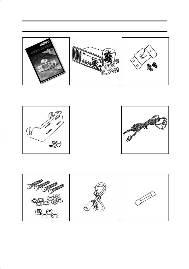
Included with your RT-2500
RT-2500 |
RT-2500 Radio |
Microphone Hanger |
Owner s Manual |
|
and Screws |
Mounting Bracket
and Knobs
DC Cord
Mounting Hardware |
Accessory Cable |
Spare Fuse |
|
|
250V 6A |
3
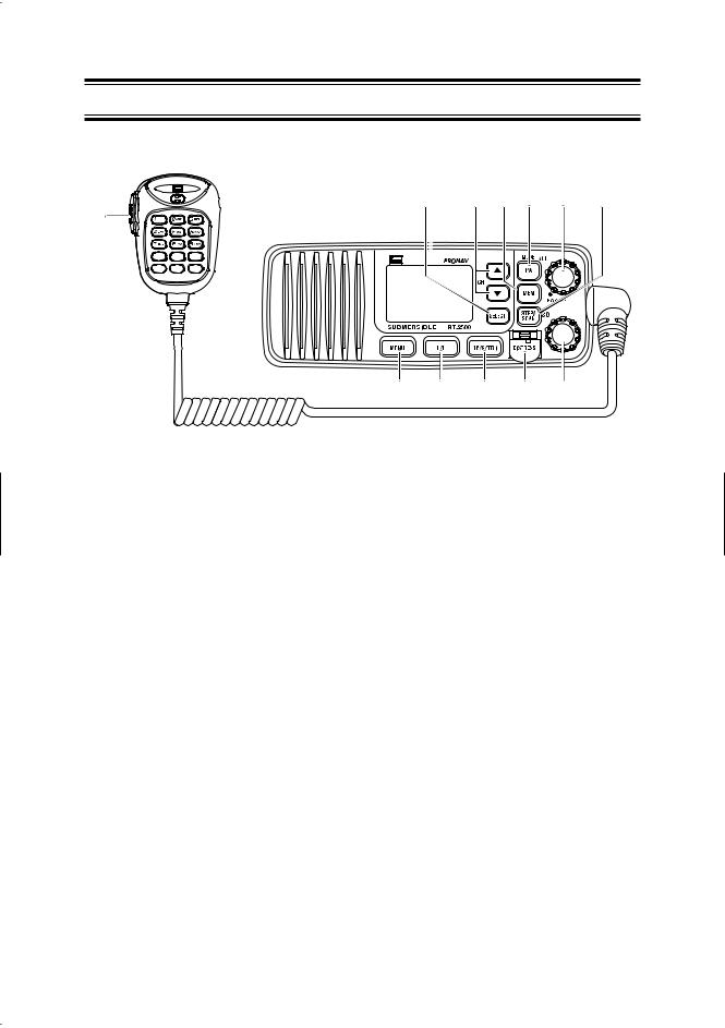
Controls and Indicators
Front panel/Microphone
5 |
6 |
7 |
8 |
9 |
10 |
1
2


 2 3
2 3


 4
4
11 12 13 14 15
1.PTT Switch - Press to transmit and release to receive.
2.6.CHANNEL/▲/▼- These keys are used to change the channel number up/down. These buttons are also used to move the cursor in Menu mode.
3.11. MENU - Press this key to enter the Menu mode.
4.5. |
SELECT - In the Menu mode this is used to select the menu options. |
10. |
STEP/SCAN - Press this key to activate the step operation. Every time |
|
this key is pushed, the radio will step to the next channel that has placed |
|
into Memory. Pressing and holding this key for 2 seconds will activate the |
|
channel scan feature. |
7.MEM - Pressing will place the currently selected channel into Memory.
8.PA/MODE - Press this key to enable the PA (Public Address) feature. Pressing and holding this key will switch between Inland Waterway Mode and Seagoing mode.
9.PWR/VOL (On/Off/Volume) - Turns the unit On or Off and adjusts the speaker volume.
12.HI/LO - Press this key to change the transmit power to either High or Low.
13.16/9/TRI - Press this key instantly change to Channel 16, Channel 9 or current channel. Pressing and holding this key for 2 seconds will activate the triple Watch Feature.
14.DISTRESS - Press this key to send a signal of distress in case of emergency.
15.SQ - Rotate this knob eliminate background noise when a signal is not being received.
4
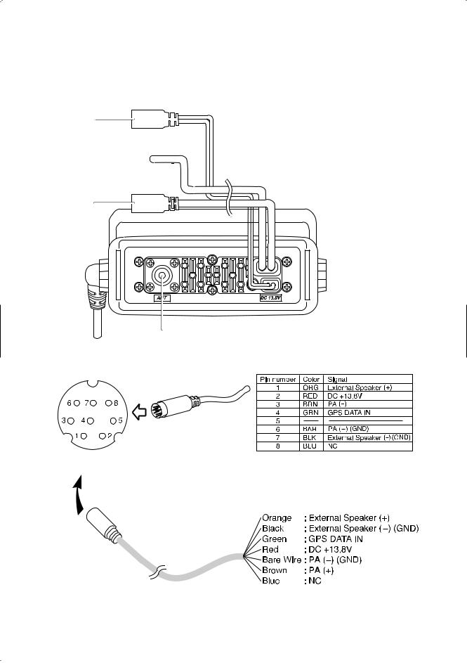
Rear Panel Connectors
1
1. DC Jack
2. ACC Connector
2 


 3. Remote Connector
4. Antenna Connector
3
4
ACC Connector
To RT-2500
Note: DC13.8V and GND are for GPS ANT.
5
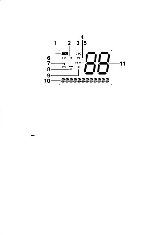
1.TX (Transmit) - Indicates transmitting.
2.HI (High) - Indicates transmit output is 25 Watts.
3.DSC - Indicates the radio is in the DSC mode.
4.TRI (Triple Watch) - Indicates Triple Watch Mode is in effect.
5.MEM (Memory) - Indicates Memory Scan Mode status for each channel selected.
6.LO (Low) - Indicates transmit output is 1 Watt.
7.WX - It blinks when the radio in the Inland Waterway mode.
8. (GPS Icon) - Indicates the following GPS receiving statuses;
-Blinking: No GPS receiver is connected at power-up or no valid position fix is available for more then 4 hours continuously.
-Animating: GPS receiver is receiving valid position data.
-Stationary: GPS receiver is waiting for a Valid position fix.
-None: GPS receiver stops receiving data.
9. (Alarm Icon) - It appears when the alarm clock is set.
10.CH TAG - This area is used for Channel Tag, Menu, and message of DSC, GPS. These messages will continually scroll from right to the left.
11.Channel Display - Indicates Channel Number in use.
6

Flow Chart for Menu Operation
MENU
|
|
|
|
|
|
|
|
|
|
|
|
|
|
|
|
|
|
|
|
|
|
|
|
|
|
|
|
|
|
|
|
|
|
|
|
|
|
|
|
|
|
|
|
|
|
|
|
|
|
|
|
|
|
|
|
|
|
DSC CALL |
|
|
|
|
|
SETUP |
|
|
|
|
|
|
|
|
|
SYSTEM |
|
|
|
|
EXIT |
|||||||
|
|
|
|
|
|
|
|
|
|
|
|
|
|
|
|
|
|
|
|
|
|
|
|
|
|
|
|
|
|
INDIVIDUAL |
|
|
|
ALARM CLOCK |
|
|
|
|
CONTRAST |
|
|
|
|
||||||||||||||
|
|
|
|
|
|
|
|
|
|
|
|
|
|
|
|
|
|
|
|
|||||||||
|
GROUP |
|
|
LOCAL TIME ADJUST |
|
|
LAMP ADJUST |
|
|
|
||||||||||||||||||
|
|
|
|
|
|
|
|
|
|
|
|
|
|
|
|
|
|
|
|
|
|
|
|
|
|
|
|
|
|
ALL SHIPS |
|
|
|
|
DAYLITE SAVE |
|
|
|
KEY BEEP |
|
|
|
|||||||||||||||
|
|
|
|
|
|
|
|
|
|
|
|
|
|
|
|
|
|
|
|
|
|
|
|
|
|
|
||
|
POS REQUEST |
|
|
DIRECTORY |
|
|
|
|
|
EXIT |
|
|
|
|||||||||||||||
|
|
|
|
|
|
|
|
|
|
|
|
|
|
|
|
|
|
|
|
|
|
|
|
|
|
|
||
|
POS SEND |
|
|
|
|
AUTO CH SW |
|
|
|
|
|
|
|
|
|
|
|
|
|
|||||||||
|
|
|
|
|
|
|
|
|
|
|
|
|
|
|
|
|
|
|
|
|
|
|
|
|
|
|
|
|
|
STANDBY |
|
|
|
|
|
POS REPLY |
|
|
|
|
|
|
|
|
|
|
|
|
|
|
|||||||
|
|
|
|
|
|
|
|
|
|
|
|
|
|
|
|
|
|
|
|
|
|
|
|
|
|
|||
|
CALL WAIT |
|
|
|
|
CH TAG |
|
|
|
|
|
|
|
|
|
|
|
|
|
|
||||||||
|
|
|
|
|
|
|
|
|
|
|
|
|
|
|
|
|
|
|
|
|
|
|
|
|
||||
|
EXIT |
|
|
|
GROUP MMSI |
|
|
|
|
|
|
|
|
|
|
|
|
|||||||||||
|
|
|
|
|
|
|
|
|
|
|
|
|||||||||||||||||
|
|
|
|
|
|
|
|
|
|
|
|
|
|
|
|
|
|
|
|
|
|
|
|
|||||
|
|
|
|
|
|
|
|
|
USER MMSI |
|
|
|
|
|
|
|
|
|
|
|
|
|
|
|||||
|
|
|
|
|
|
|
|
|
|
|
|
|
|
|
|
|
|
|
|
|
|
|||||||
|
|
|
|
|
|
|
|
|
ATIS ID |
|
|
|
|
|
|
|
|
|
|
|
|
|
|
|
|
|
||
|
|
|
|
|
|
|
|
|
|
|
|
|
|
|
|
|
|
|
|
|
|
|
|
|
|
|
|
|
|
|
|
|
|
|
|
|
|
EXIT |
|
|
|
|
|
|
|
|
|
|
|
|
|
|
|||||
NOTES: "POS SEND", "LOCAL TIME ADJUST", "DAYLITE SAVE", and "ALARM CLOCK" are not displayed in Menu when GPS module is not connected.
When the radio is in one of the following modes: Channel 16/9 mode, Scan Mode, or Triple Watch mode, and the user presses the Menu key, all of these modes are cancelled.
The Menu mode will be cancelled if the radio receives a DSC call or "EXIT" is selected.
7

Installation
Caution: The RT-2500 will only operate with a nominal 12 volt negative ground battery system.
It is important to carefully determine the most suitable location for your radio on your vessel. Electrical, mechanical, and environmental considerations must all be taken into account. You should select the optimum relationship among these considerations.
Keep in mind the flexibility designed into the RT-2500 so that you can most conveniently use it. Features which should be considered are:
1.The universal mounting bracket may be installed on either the top or bottom of a shelf, on a bulkhead, or for overhead mounting.
2.The REMOTE speaker wires can be used with an auxiliary speaker.
3.All connections are "plug-in" type for easy removal of the radio.
4.Front fire internal speaker allows convenient in-dash mounting using the optional bracket (Black - FMB322B).
Choosing a Location
Some important factors to consider in selecting the location for your RT2500.
1.Select a location that is free from spray and splash.
2.Keep the battery leads as short as possible. Direct connection to the battery is most desirable. If direct connection can not be made with the supplied power lead, any extension should be made with #10 AWG wire. Long extensions should use larger gauge wire.
3.Keep the antenna lead as short as possible. Long antenna leads can cause substantial loss of performance for both receiving and transmitting.
4.Locate your antenna as high as possible and clear from metal objects. The reliable range of coverage is a direct function of the antenna height.
5.Select a location that allows free air flow around the heat sink on the rear of the radio.
6.Select a location well away from the ship’s compass. Auxiliary speakers also should be located away from the compass.
8
Engine Noise Suppression
Interference from the noise generated by the electrical systems of engines is sometimes a problem with radios. The RT-2500 has been designed to be essentially impervious to ignition noise and alternator noise. However, in some installations it may be necessary to take measures to further reduce the effect of noise interference. All DC battery wires, antenna lead, and accessory cables should be routed away from the engine and engine compartment, and from power cabling carrying high currents.
In severe cases of noise interference, it may be necessary to install a noise suppression kit. Contact your Dealer for more information.
Antenna Considerations
A variety of antennas are available from a number of quality suppliers. It is recommended you draw upon the advice of your dealer in determining a suitable antenna for your vessel and range requirements.
In general, communication range is increased by using a high-gain antenna placed as high as possible above the water line. Antennas should be located away from metal objects. Antennas should not have excessively long coaxial feed cables.
Antenna Selection and Installation
RT-2500 has been designed to accomodate all of the popular marine VHF antennas. However, the selection and the installation of the antenna is the responsibility of the user or installer.
The antenna used with this radio should be installed using the following guidelines to insure a suitable distance between the antenna and persons close by.
Small whip antennas (3 dB) or smaller should be installed keeping at least three feet separation distance between the radiating element and people.
Larger antennas (6 dB or 9 dB) should be installed keeping at least a six foot separation distance.
No person should touch the antenna or come into the separation distance when the radio is transmitting.
9
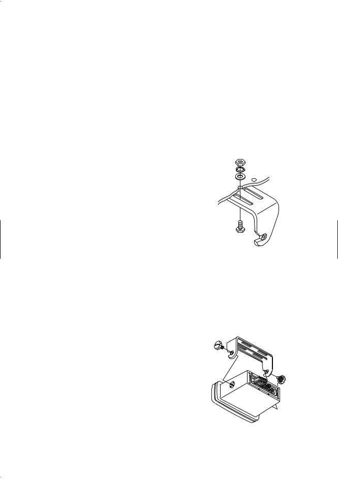
Installing the RT-2500
After you have carefully considered the various factors affecting your choice of location, position the radio (with the bracket, microphone, power cord, antenna and any auxiliary cables installed) into the selected location to assure there is no interference with the surrounding items. Mark the location of the mounting bracket. Remove the bracket from the radio and use it as a template to mark the holes to be drilled for the mounting hardware. Drill the holes and mount the bracket with hardware compatible with the material of the mounting surface.
Note: This HEXAGON HEAD BOLT is only for mounting the bracket with hardware. Do not use it for installing the radio in the mounting bracket.
Connect the red wire of the supplied power cord to the positive (+) battery supply. Connect the black wire of the power cord to the negative
(–) battery supply. The power cord is equipped with a fuse to protect the radio. Use only a six (6) ampere fast blow fuse for replacement. Connect the power cord to the keyed connector on the power "pigtail".
Connect the antenna and all other auxiliary cables and accessories. Install the radio in the mounting bracket and connect all cables and accessories to the appropriate jacks and connectors.
Note: Do not use any other mounting knobs than the ones enclosed. Do not insert the knobs without attaching the bracket.
10
Operation
POWER On/Off
Turn the unit On by rotating the PWR/VOL control clockwise.
Adjust the volume to a comfortable level.
When you turn the unit On, you will hear a beep, and the greeting message below appears on the LCD for 3 seconds.
Note: When you turn On the radio for the first time after purchase, the channel 16 will appear on the LCD.
Last Channel Memory
The RT-2500 memorizes the last channel selected before you turn Off the radio. For example, if you turn Off the radio on CH 12, it will be on that channel when turned back On.
Note: In order for the last channel to be memorized, you must have the radio on that channel for 3 seconds.
11

SQUELCH
Turn SQ fully clockwise. This raises the “Squelch Gate” so high that only very strong signals can get through.
Strong Signals 
Medium Signals 
Weak Signals 
Noise 
Turn SQ fully counterclockwise until you hear a hiss. This lowers the “Squelch Gate” so that everything gets through - noise, weak signals, and strong signals.
Strong Signals
Medium Signals
Weak Signals
Noise 
Turn SQ back clockwise until the hiss stops. Now the “Squelch Gate” allows only strong signals through.
Strong Signals
Medium Signals 
Weak Signals 
Noise 
12
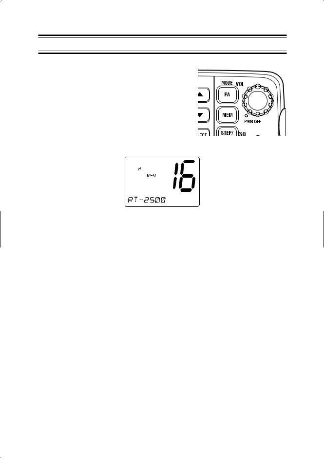
COAST GUARD CHANNEL 16/CHANNEL 9 COMMUNICATIONS
To access Coast Guard Channel 16 or Channel 9 communications, press 16/9/TRI. You can access Coast Guard 16 CH instantly while tuned to another channel. Press 16/9/TRI again for Channel 9 Calling communications. Press 16/9/TRI a third time to return to the channel selected prior to accessing Coast Guard Channel 16/Channel 9 commnunications.
The display will indicate the selected channel.
To cancel Coast Guard Channel 16/Channel 9 communications:
● Press 16/9/TRI until the previous channel setting appears.
--or--
● Press CH ▲, ▼ or STEP/SCAN.
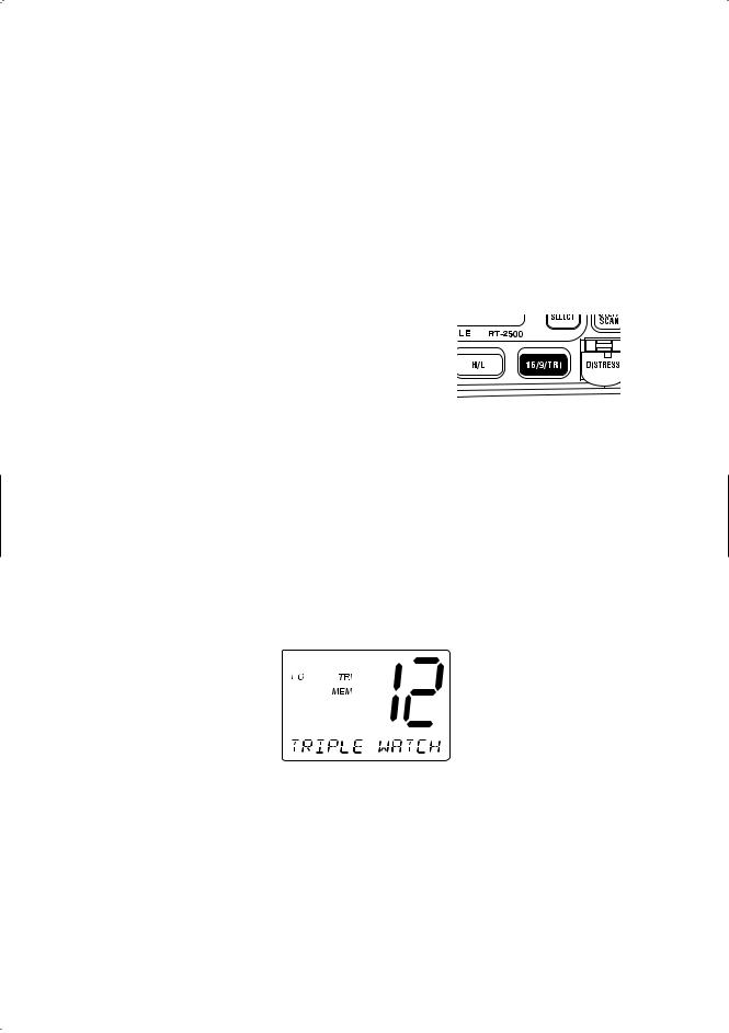
TRIPLE WATCH
Triple Watch monitors Channel 16, Channel 9, and the current Marine Channel or Weather Channel.
To activate Triple Watch, press and hold 16/9/TRI for 2 seconds. TRI appears on the LCD, indicating Triple Watch mode is in effect. If a signal is received on either Channel 16 or Channel 9, the radio remains on that channel until the signal ends.
Press and hold 16/9/TRI for 2 seconds to cancel the Triple Watch mode.
Note: While in Triple Watch mode, you can change the currently selected channel using CH ▲ and ▼.
A momentary press of the 16/9/TRI button interrupts Triple Watch mode and remains on channel 16, or on channel 9 if you press 16/9/TRI once more. To return to the Triple Watch mode, simply press the button again.
13
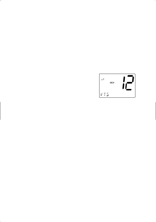
MANUAL TUNING
To manually select a channel, press CH ▲ or ▼. Communication channels are located on channel 01-28 and 60-88.
MEM (Entering channel numbers into Memory Scan)
You can enter channels into Memory Scan for instant scanning at any time. When a channel is selected for Memory Scan, MEM appears on the LCD display.
To enter a channel into Memory Scan, select the channel you want to store by using CH ▲ and ▼, and then press MEM. The channel is stored in Memory Scan and MEM appears on the LCD display.
To cancel the channel in Memory, press MEM.
Triple Watch Scan
To turn Triple Watch Scan On, press and hold STEP/SCAN for 2 seconds. While the current channel is scanned, Channel 16 and Channel 9 are also scanned every 2 seconds. Then TRI appears.
Normal Scan
Normal Scan is performed only when the memory CH is registered.
To turn Normal Scan On, press and hold 16/9/TRI for 2 seconds in Triple watch Scan mode. Although Memory CH is scanned, Channel 16 and Channel 9 are not.
14
TRANSMITTING
Note: Channel 70 is DSC only. All the available marine channel are located on page 49.
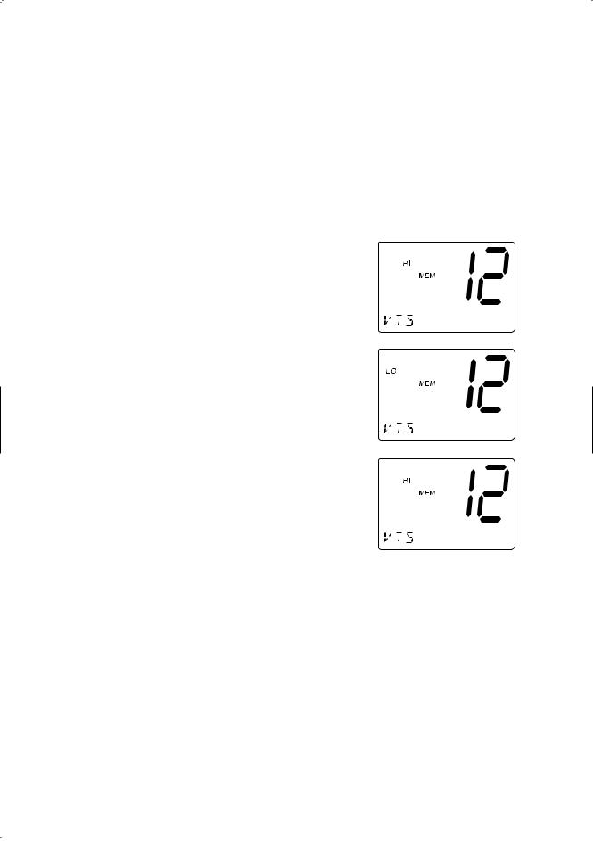
SETTING TX OUTPUT
Caution: It is important to remember to use the LO position in port or for short range communications.
1.When you turn the radio On for the first
time, the unit is automatically set to transmit at 25 watts (HI).
2.Press HI/LO to change the transmitter
output to 1 watt (LO).
3.Press HI/LO again to change back to 25
watts (HI).
Note: Each time the HI/LO is pressed a short tone sounds. When the channel is set as LO power channel, you can
transmit at 25 watts (HI) by pressing and holding HI/LO during the call (except for CH75 and CH76).
15
 Loading...