

Radiant Systems C-10508, C-12012, C-20008, C-18008, C-9008 User Manual
...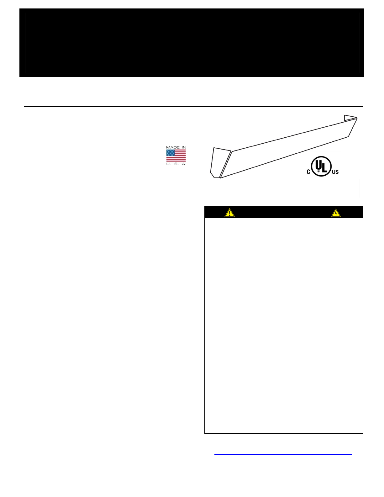
COMFORT-COVE
Installation Instructions & Specifications
Read Carefully – These instructions are written to
help prevent difficulties that might arise during
Studying the
Disconnect all power to heater at main service
Do not allow foreign objects to enter any
recommended by the
This heater is not approved for use in corrosive
The heater must be mounted at least 6’ (182.8
d bottom
Thank you for choosing
American Made Product
, proudly manufacturers
Then & Now
Cove® heater
antly been innovated, engineered,
From the Owner
your heating needs, we take pride in our work
such as ours, we wouldn’t be
R. Kirk Sharp
Warm Your Floor and More™
www.radiantsystemsinc.com
1-800-314-9303 8AM – 5PM CST
FILE #
CANADA: KKWS7.E99303
Comfort-Cove®!
Radiant Systems, Inc.
Comfort-Cove® in the Heartland of America;
in Valentine, Nebraska, USA. Our ComfortCove® heaters are even compliant with the Buy
American Act.
Model C-Series
USA: KKWS.E99303
We started like most American businesses, by
an individual with an idea and determination.
Our story began back in 1984 with founder and
owner, Kirk Sharp. Production began in his
basement and is now operating out of a 30,000square foot factory. Comfort-
has const
and improved for optimum performance, for
the last 28 years.
Thank you for choosing Comfort-Cove® for
and would like to thank you for supporting a
local business
here without you.
installation of Comfort-Cove® heaters.
instructions saves time.
TO REDUCE RISK OF ELECTRIC S HOCK :
1.
panel before wiring or servicing.
2. All wiring must be in accordance with the National
Electrical Code.
3. Verify the power supply voltage coming to heater
matches the rating printed on the heater
nameplate.
4. This heater is hot when in use. Do not touch.
5.
ventilation opening.
6. Do not use it in areas where flammable liquids are
used or stored.
7. Use this heater only as described in this manual,
any other use is not
manufacturer.
8.
atmospheres.
9.
cm) or (1.83 m) above the floor.
10. Refer to these instructions for top an
clearance requirements.
MAINTENANCE SCHEDULE:
1. No Maintenance Required
R. Kirk Sharp
1. Locate a wall stud for each bracket such that when the
heater is attached to the brackets they are spaced
CAUTION
1. Do not recess Comfort-Cove® heater
Never install heater without supplied wall
Do not use plastic conduits for direct
5. DO NOT PAINT HEATE R IN ANY M ANNER
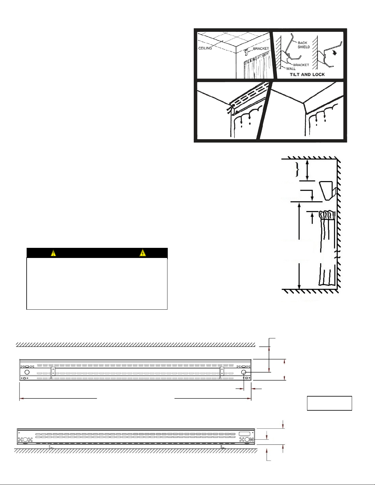
34” TO 132”
1-1/2”
4-3/4” MIN. (DRY WALL CEILING)
CEILING
REAR VIEW
TOP VIEW
WALL
2-7/8”
1-1/4”
4”
Page | 2
Figure #1
Comfort-Cove® Mounting & Clearances
WALL
CURTAINS
CEILING
FLOOR
6’ MIN
1” MIN. BETWEEN BOTTOM
2-1/2” MIN. (DRY WALL CEILING)
CEILING TO CENTER OF
KNOCK OUT
approximately 12” from heater end.
2. Attach brackets to wall studs with wood screws
3. Attach back shield to brackets by tilting Back Shield
4. Hang Front Panel on Back Shield and complete wiring
5. Complete wiring as shown on Page 3. Can be wired
6. Secure Front Panel to Back Shield using supplied
7. Attach End Caps (Teflon washer not needed).
8. Loosen the two outermost painted screws holding the
9. When Comfort-Cove® is first energized, an initial break-
provided, use template provided to mark screw locations
depending upon type of ceiling. (Figure 1)
back and allowing Back Shield slot to fall onto bracket
hook, then simply bring Back Shield forward locking into
place.
as directed. (Note: if left and or right clearan ce is
restricted attach end caps to front panel before hanging)
from either end.
painted screws and Teflon washers.
painted Front Panel in place about one revolution, (this
is to allow for thermal expansion).
in fragrance may be noticed – this is normal. (Do not
touch while hot)
4-1/2” MIN. (LAY IN, VINYL, LATH &
PLASTER OR PLASTIC MOLDING
OF HEATER AND ANY FABIRC
2.
brackets
3. Heater should not be blocked in any manner
4.
connection to Comfort-Cove®
CLEARANCE
TO FLOOR
6-3/4” MIN. (LA Y IN, VINYL, LATH &
PLASTER OR PLASTIC MOLDING
 Loading...