

Page 1

Installation and Operation Manual
M
FCD-IPM
E1/T1 or Fractional E1/T1
odular Access Device
with Integrated Router
Page 2

Page 3

FCD-IPM
E1/T1 or Fractional E1/T1 Modular Access Device with
Integrated Router
Installation and Operation Manual
Notice
This manual contains information that is proprietary to RAD Data Communications Ltd. ("RAD"). No
part of this publication may be reproduced in any form whatsoever without prior written approval by
RAD Data Communications.
Right, title and interest, all information, copyrights, patents, know-how, trade secrets and other
intellectual property or other proprietary rights relating to this manual and to the FCD-IPM and any
software components contained therein are proprietary products of RAD protected under international
copyright law and shall be and remain solely with RAD.
FCD-IPM is a registered trademark of RAD. No right, license, or interest to such trademark is granted
hereunder, and you agree that no such right, license, or interest shall be asserted by you with respect
to such trademark.
You shall not copy, reverse compile or reverse assemble all or any portion of the Manual or the FCDIPM. You are prohibited from, and shall not, directly or indirectly, develop, market, distribute, license,
or sell any product that supports substantially similar functionality as the FCD-IPM, based on or derived
in any way from the FCD-IPM. Your undertaking in this paragraph shall survive the termination of this
Agreement.
This Agreement is effective upon your opening of the FCD-IPM package and shall continue until
terminated. RAD may terminate this Agreement upon the breach by you of any term hereof. Upon
such termination by RAD, you agree to return to RAD the FCD-IPM and all copies and portions
thereof.
For further information contact RAD at the address below or contact your local distributor.
International Headquarters
RAD Data Communications Ltd.
24 Raoul Wallenberg St.
Tel Aviv 69719 Israel
Tel: 972-3-6458181
Fax: 972-3-6498250
E-mail: market@rad.com
© 1991-2003 RAD Data Communications Ltd. Publication No. 702-200-08/03
U.S. Headquarters
RAD Data Communications Inc.
900 Corporate Drive
Mahwah, NJ 07430 USA
Tel: (201) 529-1100, Toll free: 1-800-444-7234
Fax: (201) 529-5777
E-mail: market@radusa.com
Page 4

Limited Warranty
RAD warrants to DISTRIBUTOR that the hardware in the FCD-IPM to be delivered hereunder shall be
free of defects in material and workmanship under normal use and service for a period of twelve (12)
months following the date of shipment to DISTRIBUTOR.
If, during the warranty period, any component part of the equipment becomes defective by reason of
material or workmanship, and DISTRIBUTOR immediately notifies RAD of such defect, RAD shall have
the option to choose the appropriate corrective action: a) supply a replacement part, or b) request
return of equipment to its plant for repair, or c) perform necessary repair at the equipment's location.
In the event that RAD requests the return of equipment, each party shall pay one-way shipping costs.
RAD shall be released from all obligations under its warranty in the event that the equipment has been
subjected to misuse, neglect, accident or improper installation, or if repairs or modifications were
made by persons other than RAD's own authorized service personnel, unless such repairs by others
were made with the written consent of RAD.
The above warranty is in lieu of all other warranties, expressed or implied. There are no warranties
which extend beyond the face hereof, including, but not limited to, warranties of merchantability and
fitness for a particular purpose, and in no event shall RAD be liable for consequential damages.
RAD shall not be liable to any person for any special or indirect damages, including, but not limited to,
lost profits from any cause whatsoever arising from or in any way connected with the manufacture,
sale, handling, repair, maintenance or use of the FCD-IPM, and in no event shall RAD's liability exceed
the purchase price of the FCD-IPM.
DISTRIBUTOR shall be responsible to its customers for any and all warranties which it makes relating
to FCD-IPM and for ensuring that replacements and other adjustments required in connection with the
said warranties are satisfactory.
Software components in the FCD-IPM are provided "as is" and without warranty of any kind. RAD
disclaims all warranties including the implied warranties of merchantability and fitness for a particular
purpose. RAD shall not be liable for any loss of use, interruption of business or indirect, special,
incidental or consequential damages of any kind. In spite of the above RAD shall do its best to provide
error-free software products and shall offer free Software updates during the warranty period under
this Agreement.
RAD's cumulative liability to you or any other party for any loss or damages resulting from any claims,
demands, or actions arising out of or relating to this Agreement and the FCD-IPM shall not exceed the
sum paid to RAD for the purchase of the FCD-IPM. In no event shall RAD be liable for any indirect,
incidental, consequential, special, or exemplary damages or lost profits, even if RAD has been advised of
the possibility of such damages.
This Agreement shall be construed and governed in accordance with the laws of the State of Israel.
Page 5

General Safety Instructions
The following instructions serve as a general guide for the safe installation and operation of
telecommunications products. Additional instructions, if applicable, are included inside the manual.
Safety Symbols
This symbol may appear on the equipment or in the text. It indicates
potential safety hazards regarding product operation or maintenance to
operator or service personnel.
Warning
Danger of electric shock! Avoid any contact with the marked surface while
the product is energized or connected to outdoor telecommunication lines.
.
Warning
Protective earth: the marked lug or terminal should be connected to the building
protective earth bus.
Some products may be equipped with a laser diode. In such cases, a label
with the laser class and other warnings as applicable will be attached near
the optical transmitter. The laser warning symbol may be also attached.
Please observe the following precautions:
• Before turning on the equipment, make sure that the fiber optic cable is
intact and is connected to the transmitter.
• Do not attempt to adjust the laser drive current.
• Do not use broken or unterminated fiber-optic cables/connectors or look
straight at the laser beam.
• The use of optical devices with the equipment will increase eye hazard.
• Use of controls, adjustments or performing procedures other than those
specified herein, may result in hazardous radiation exposure.
ATTENTION: The laser beam may be invisible!
Always observe standard safety precautions during installation, operation and maintenance of this
product. Only qualified and authorized service personnel should carry out adjustment, maintenance or
repairs to this product. No installation, adjustment, maintenance or repairs should be performed by
either the operator or the user.
Page 6

Handling Energized Products
General Safety Practices
Do not touch or tamper with the power supply when the power cord is connected. Line voltages may
be present inside certain products even when the power switch (if installed) is in the OFF position or a
fuse is blown. For DC-powered products, although the voltages levels are usually not hazardous,
energy hazards may still exist.
Before working on equipment connected to power lines or telecommunication lines, remove jewelry
or any other metallic object that may come into contact with energized parts.
Unless otherwise specified, all products are intended to be grounded during normal use. Grounding is
provided by connecting the mains plug to a wall socket with a protective earth terminal. If an earth lug
is provided on the product, it should be connected to the protective earth at all times, by a wire with a
diameter of 18 AWG or wider. Rack-mounted equipment should be mounted only in earthed racks
and cabinets.
Always make the ground connection first and disconnect it last. Do not connect telecommunication
cables to ungrounded equipment. Make sure that all other cables are disconnected before
disconnecting the ground.
Connection of AC Mains
Make sure that the electrical installation complies with local codes.
Always connect the AC plug to a wall socket with a protective ground.
The maximum permissible current capability of the branch distribution circuit that supplies power to
the product is 16A. The circuit breaker in the building installation should have high breaking capacity
and must operate at short-circuit current exceeding 35A.
Always connect the power cord first to the equipment and then to the wall socket. If a power switch is
provided in the equipment, set it to the OFF position. If the power cord cannot be readily
disconnected in case of emergency, make sure that a readily accessible circuit breaker or emergency
switch is installed in the building installation.
Connection of DC Mains
Unless otherwise specified in the manual, the DC input to the equipment is floating in reference to the
ground. Any single pole can be externally grounded.
Due to the high current capability of DC mains systems, care should be taken when connecting the DC
supply to avoid short-circuits and fire hazards.
DC units should be installed in a restricted access area, i.e. an area where access is authorized only to
qualified service and maintenance personnel.
Make sure that the DC supply is electrically isolated from any AC source and that the installation
complies with the local codes.
The maximum permissible current capability of the branch distribution circuit that supplies power to
the product is 16A. The circuit breaker in the building installation should have high breaking capacity
and must operate at short-circuit current exceeding 35A.
Before connecting the DC supply wires, ensure that power is removed form the DC circuit. Locate the
circuit breaker of the panel board that services the equipment and switch it to the OFF position. When
connecting the DC supply wires, first connect the ground wire to the corresponding terminal, then the
positive pole and last the negative pole. Switch the circuit breaker back to the ON position.
A readily accessible disconnect device that is suitably rated and approved should be incorporated in
the building installation.
Page 7

Connection of Data and Telecommunications Cables
Data and telecommunication interfaces are classified according to their safety status.
The following table lists the status of several standard interfaces. If the status of a given port differs from
the standard one, a notice will be given in the manual.
Ports Safety Status
V.11, V.28, V.35, V.36, RS-530,
X.21, 10 BaseT, 100 BaseT,
Unbalanced E1, E2, E3, STM, DS-2,
DS-3, S-Interface ISDN, Analog voice
E&M
xDSL (without feeding voltage),
Balanced E1, T1, Sub E1/T1
FXS (Foreign Exchange Subscriber) TNV-2 Telecommunication Network Voltage-2:
FXO (Foreign Exchange Office), xDSL
(with feeding voltage), U-Interface
ISDN
SELV Safety Extra Low Voltage:
Ports which do not present a safety hazard. Usually
up to 30 VAC or 60 VDC.
TNV-1 Telecommunication Network Voltage-1:
Ports whose normal operating voltage is within the
limits of SELV, on which overvoltages from
telecommunications networks are possible.
Ports whose normal operating voltage exceeds the
limits of SELV (usually up to 120 VDC or telephone
ringing voltages), on which overvoltages from
telecommunication networks are not possible. These
ports are not permitted to be directly connected to
external telephone and data lines.
TNV-3 Telecommunication Network Voltage-3:
Ports whose normal operating voltage exceeds the
limits of SELV (usually up to 120 VDC or telephone
ringing voltages), on which overvoltages from
telecommunication networks are possible.
Always connect a given port to a port of the same safety status. If in doubt, seek the assistance of a
qualified safety engineer.
Always make sure that the equipment is grounded before connecting telecommunication cables. Do
not disconnect the ground connection before disconnecting all telecommunications cables.
Some SELV and non-SELV circuits use the same connectors. Use caution when connecting cables.
Extra caution should be exercised during thunderstorms.
When using shielded or coaxial cables, verify that there is a good ground connection at both ends. The
earthing and bonding of the ground connections should comply with the local codes.
The telecommunication wiring in the building may be damaged or present a fire hazard in case of
contact between exposed external wires and the AC power lines. In order to reduce the risk, there are
restrictions on the diameter of wires in the telecom cables, between the equipment and the mating
connectors.
Page 8

A
n
Caution
To reduce the risk of fire, use only No. 26 AWG or larger telecommunication line cords.
ttentio
Pour réduire les risques s’incendie, utiliser seulement des conducteurs de
télécommunications 26 AWG ou de section supérieure.
Some ports are suitable for connection to intra-building or non-exposed wiring or cabling only. In such
cases, a notice will be given in the installation instructions.
Do not attempt to tamper with any carrier-provided equipment or connection hardware.
Electromagnetic Compatibility (EMC)
The equipment is designed and approved to comply with the electromagnetic regulations of major
regulatory bodies. The following instructions may enhance the performance of the equipment and will
provide better protection against excessive emission and better immunity against disturbances.
A good earth connection is essential. When installing the equipment in a rack, make sure to remove all
traces of paint from the mounting points. Use suitable lock-washers and torque. If an external
grounding lug is provided, connect it to the earth bus using braided wire as short as possible.
The equipment is designed to comply with EMC requirements when connecting it with unshielded
twisted pair (UTP) cables. However, the use of shielded wires is always recommended, especially for
high-rate data. In some cases, when unshielded wires are used, ferrite cores should be installed on
certain cables. In such cases, special instructions are provided in the manual.
Disconnect all wires which are not in permanent use, such as cables used for one-time configuration.
The compliance of the equipment with the regulations for conducted emission on the data lines is
dependent on the cable quality. The emission is tested for UTP with 80 dB longitudinal conversion loss
(LCL).
Unless otherwise specified or described in the manual, TNV-1 and TNV-3 ports provide secondary
protection against surges on the data lines. Primary protectors should be provided in the building
installation.
The equipment is designed to provide adequate protection against electro-static discharge (ESD).
However, it is good working practice to use caution when connecting cables terminated with plastic
connectors (without a grounded metal hood, such as flat cables) to sensitive data lines. Before
connecting such cables, discharge yourself by touching earth ground or wear an ESD preventive wrist
strap.
FCC-15 User Information
This equipment has been tested and found to comply with the limits of the Class A digital device,
pursuant to Part 15 of the FCC rules. These limits are designed to provide reasonable protection
against harmful interference when the equipment is operated in a commercial environment. This
equipment generates, uses and can radiate radio frequency energy and, if not installed and used in
accordance with the Installation and Operation manual, may cause harmful interference to the radio
communications. Operation of this equipment in a residential area is likely to cause harmful
interference in which case the user will be required to correct the interference at his own expense.
Page 9

A
A
Canadian Emission Requirements
This Class A digital apparatus meets all the requirements of the Canadian Interference-Causing
Equipment Regulation.
Cet appareil numérique de la classe A respecte toutes les exigences du Règlement sur le matériel
brouilleur du Canada.
Warning per EN 55022 (CISPR-22)
Warning
vertissement
chtung
Conventions
Note
Caution
This is a class A product. In a domestic environment, this product may cause
radio interference, in which case the user will be required to take adequate
measures.
Cet appareil est un appareil de Classe A. Dans un environnement résidentiel, cet
appareil peut provoquer des brouillages radioélectriques. Dans ces cas, il peut
être demandé à l’utilisateur de prendre les mesures appropriées.
Dieses ist ein Gerät der Funkstörgrenzwertklasse A. In Wohnbereichen können
bei Betrieb dieses Gerätes Rundfunkströrungen auftreten, in welchen Fällen der
Benutzer für entsprechende Gegenmaßnahmen verantwortlich ist.
A note draws attention to a general rule for a procedure, or to exceptions to a rule.
A caution warns of possible damage to the equipment if a procedure is not
followed correctly.
A warning alerts to the presence of important operating and maintenance
(servicing) instructions in the literature accompanying the equipment. If these
instructions are not followed exactly, possible bodily injury may occur.
Warning
Page 10

Page 11

Quick Start Guide
If you are familiar with FCD-IPM, use this guide to prepare it for operation.
1. Installing and Operating FCD-IPM
To install FCD-IPM:
1. Unpack the unit.
2. If working with E1 unbalanced interface, open the unit to switch factory setting
of jumper from BAL to UNBAL.
3. Close the unit.
4. Connect interface cables to the unit.
5. Connect the power to the unit.
6. Turn on the unit.
7. Configure the unit using the Quick Setup Menu or Advanced Menu.
Installing and Operating FCD-IPM 1
Page 12

Quick Start Guide FCD-IPM Installation and Operation Manual
2 Installing and Operating FCD-IPM
Page 13

Contents
Chapter 1. Introduction
1.1 Overview .......................................................................................................... 1-1
Versions...................................................................................................................1-1
Applications.............................................................................................................1-3
Features...................................................................................................................1-4
1.2 Physical Description .......................................................................................... 1-5
1.3 Functional Description ...................................................................................... 1-5
Main Link and Sublink Characteristics ......................................................................1-6
IO Data Channel Interfaces...................................................................................... 1-7
System Timing Considerations..................................................................................1-7
Time Slot Handling .................................................................................................. 1-8
Integrated Router.....................................................................................................1-8
Bridging...................................................................................................................1-8
Protocols .................................................................................................................1-9
Management ...........................................................................................................1-9
1.4 Technical Specifications ..................................................................................1-11
Chapter 2. Installation and Setup
2.1 Site Requirements & Prerequisites ..................................................................... 2-1
2.2 Package Contents.............................................................................................. 2-2
2.3 Equipment Needed........................................................................................... 2-2
2.4 Installation and Setup........................................................................................ 2-2
Setting Internal Jumpers and Switches ......................................................................2-2
Fuses .......................................................................................................................2-3
2.5 Interfaces and Connections ............................................................................... 2-4
E1/T1 Link Connections ...........................................................................................2-4
IO Data Channel Connections .................................................................................2-4
Control Port Connection .......................................................................................... 2-5
Connecting the Power .............................................................................................2-5
Chapter 3. Operation
3.1 Introduction ...................................................................................................... 3-1
3.2 Indicators .......................................................................................................... 3-1
Front Panel Indicators ..............................................................................................3-1
Rear Panel Indicators ...............................................................................................3-3
3.3 Operating Instructions .......................................................................................3-3
Turning On..............................................................................................................3-3
Normal Indications ..................................................................................................3-3
Fault Indications ......................................................................................................3-5
Turning Off..............................................................................................................3-5
3.4 Connecting to the ASCII Terminal ..................................................................... 3-5
Connecting the Terminal Emulator...........................................................................3-5
Password Protection.................................................................................................3-6
FCD-IPM Installation and Operation Manual i
Page 14

Table of Contents
Chapter 4. Configuration
4.1 Overview .......................................................................................................... 4-1
4.2 Main Menu ....................................................................................................... 4-2
4.3 Quick Setup Menu............................................................................................ 4-2
Quick Setup Parameters...........................................................................................4-3
Quick Setup Menu Examples ...................................................................................4-5
WAN Settings ..........................................................................................................4-7
LAN Settings ............................................................................................................4-9
ISDN Settings.........................................................................................................4-11
Frame Relay Settings..............................................................................................4-11
DLCI Number........................................................................................................4-11
V.24 Async Settings................................................................................................4-12
Security Settings.....................................................................................................4-12
4.4 Security Setup Menu .......................................................................................4-13
Device Access Restriction.......................................................................................4-14
Firewall Option......................................................................................................4-15
IP Address Translation (NAT)..................................................................................4-18
4.5 Advanced Setup Menu.................................................................................... 4-20
Setup Menu...........................................................................................................4-20
Device Control Menu ............................................................................................4-21
4.6 View Menu ..................................................................................................... 4-26
Configuration.........................................................................................................4-27
Interface Connections ............................................................................................4-29
Routing Tables.......................................................................................................4-29
Statistics.................................................................................................................4-35
SHDSL Status and Statistics ....................................................................................4-35
E1/T1 Diagnostics ..................................................................................................4-38
E1/T1 Alarms Log File.............................................................................................4-40
4.7 Diagnostic Tools Menu.................................................................................... 4-41
Chapter 5. Setup Menu
5.1 Host Parameters Menu...................................................................................... 5-3
Device ID................................................................................................................5-4
IP Host ....................................................................................................................5-5
SNMP Manager Table..............................................................................................5-7
TFTP (Trivial File Transfer Protocol) ..........................................................................5-8
RADIUS (Authentication and Billing) ........................................................................5-9
5.2 Routing/Bridging Menu ................................................................................... 5-11
Interface Routing/Bridging Mode............................................................................5-12
Static Stations and Nets..........................................................................................5-15
IP Routings Settings................................................................................................5-17
IPX Routing Settings ...............................................................................................5-25
Station Ageing........................................................................................................5-27
5.3 Interface Parameters Menu ............................................................................. 5-28
Link Settings Menu ................................................................................................5-29
SHDSL Settings......................................................................................................5-31
E1/T1 Settings ........................................................................................................5-34
ISDN Settings Menu...............................................................................................5-67
Frame Relay Settings..............................................................................................5-70
ii FCD-IPM Installation and Operation Manual
Page 15

Table of Contents
5.4 Access Control (Security) Menu ....................................................................... 5-75
External Access Security (only relevant to Link with PPP Protocol)...........................5-76
Device Security Identity (PPP only).........................................................................5-78
Security Host/Guest (PPP only)...............................................................................5-79
Login Script Setup..................................................................................................5-79
5.5 WAN Economy Menu ..................................................................................... 5-82
Filters ....................................................................................................................5-83
Connection on Demand ........................................................................................5-92
Spoofing ................................................................................................................5-97
5.6 Factory Default Options .................................................................................. 5-99
Chapter 6. Troubleshooting and Diagnostics
6.1 General Troubleshooting................................................................................... 6-1
6.2 E1/T1 and Voice Troubleshooting...................................................................... 6-1
6.3 Router Connections Troubleshooting ................................................................ 6-2
IP connection to LAN is DOWN ..............................................................................6-2
IP Connection to WAN is DOWN............................................................................6-2
Appendix A. Interface Specifications and Cable Diagrams
Appendix B. Boot Manager
Appendix C. SNMP Management
Appendix D. Glossary
FCD-IPM Installation and Operation Manual iii
Page 16

Table of Contents
List of Figures
1-1. FCD-IPM with PBX and LAN ..................................................................................... 1-3
1-2. FCD-IPM with Eight Telephones and LAN over SHDSL.............................................. 1-3
1-3. FCD-IPM General View............................................................................................. 1-5
1-4. FCD-IPM Functional Block Diagram .......................................................................... 1-6
2-1. Location of Internal BAL/UNBAL Jumpers.................................................................. 2-3
2-2. FCD-IPM Rear Panel ................................................................................................. 2-4
3-1. FCD-IPM Front Panel ................................................................................................3-1
3-2. Connecting to Terminal Emulator .............................................................................. 3-6
4-1. FCD-IPM Main Menu................................................................................................ 4-2
4-2. T1 Interface Quick Setup Screen ............................................................................... 4-5
4-3. E1 Interface Quick Setup Screen ............................................................................... 4-6
4-4. Setting up the IP Mask............................................................................................. 4-10
4-5. Security Setup Menu Outline .................................................................................. 4-13
4-6. Security Setup Menu ............................................................................................... 4-13
4-7. Configuring Firewalls ............................................................................................... 4-17
4-8. Firewall Setup Menu ............................................................................................... 4-17
4-9. Firewall Interfaces Menu ......................................................................................... 4-17
4-10. Firewall Rules Menu ..............................................................................................4-18
4-11. IP Address Translation Menu .................................................................................4-18
4-12. IP Address Translation ...........................................................................................4-18
4-13. IP Address Transparent ..........................................................................................4-19
4-14. Advanced Menu Outline ....................................................................................... 4-20
4-15. Advanced Menu.................................................................................................... 4-20
4-16. Device Control Menu Outline ............................................................................... 4-21
4-17. Device Control Menu............................................................................................ 4-21
4-18. Software Download Menu..................................................................................... 4-22
4-19. Using the Dual Image Flash ................................................................................... 4-22
4-20. Downloading from a TFTP Server .......................................................................... 4-23
4-21. Software Download Menu..................................................................................... 4-23
4-22. Downloading/Uploading Parameters .....................................................................4-24
4-23. View Menu Outline............................................................................................... 4-26
4-24. View Menu ...........................................................................................................4-27
4-25. View Configuration Screen .................................................................................... 4-28
4-26. Interface Connections Screen ................................................................................ 4-29
4-27. Routing Tables Menu............................................................................................. 4-29
4-28. Bridge Table.......................................................................................................... 4-30
4-29. IP Interfaces Table .................................................................................................4-30
4-30. IP Routing Table.................................................................................................... 4-30
4-31. IPX Routing Table.................................................................................................. 4-31
4-32. IPX Services Table ................................................................................................. 4-32
4-33. ARP Table .............................................................................................................4-32
4-34. IP Address Pool (DHCP) Table............................................................................... 4-33
4-35. OSPF Related Information Menu........................................................................... 4-33
4-36. OSPF Interfaces Table ...........................................................................................4-33
iv FCD-IPM Installation and Operation Manual
Page 17

Table of Contents
4-37. OSPF Neighbors Table ..........................................................................................4-34
4-38. OSPF Database Table............................................................................................ 4-34
4-39. LAN Statistics......................................................................................................... 4-35
4-40. SHDSL Status ........................................................................................................4-36
4-41. SHDSL Statistics over Intervals ...............................................................................4-37
4-42. T1 Diagnostics....................................................................................................... 4-38
4-43. E1 Diagnostics .......................................................................................................4-38
4-44. E1 Alarms Screen................................................................................................... 4-40
4-45. T1 Alarms Screen ..................................................................................................4-40
4-46. Diagnostic Tools Menu Outline ............................................................................. 4-41
4-47. Diagnostic Tools Menu.......................................................................................... 4-41
4-48. Pinging an IP Host ................................................................................................. 4-41
4-49. Ping Terminal Screen............................................................................................. 4-42
5-1. Setup Menu Outline.................................................................................................. 5-1
5-2. Setup Menu .............................................................................................................. 5-1
5-3. Host Parameters Menu Outline .................................................................................5-3
5-4. Host Parameters Menu ..............................................................................................5-4
5-5. Device ID Menu........................................................................................................ 5-4
5-6. IP Host Menu ............................................................................................................ 5-5
5-7. Default Gateway ....................................................................................................... 5-7
5-8. SNMP Manager Table Menu ..................................................................................... 5-7
5-9. TFTP Menu ...............................................................................................................5-8
5-10. File Transfer to and from TFTP Server ......................................................................5-8
5-11. RADIUS Menu ........................................................................................................ 5-9
5-12. Routing Menu Outline........................................................................................... 5-11
5-13. Routing/Bridging menu.......................................................................................... 5-12
5-14. Interface Routing Bridging Mode Menu ................................................................. 5-12
5-15. Adding Static Stations and Nets .............................................................................5-15
5-16. Router 2 set to “Next Hop” in FCD-IPM ................................................................5-16
5-17. IP Routing Settings................................................................................................. 5-17
5-18. WAN and LAN Interface Addresses ....................................................................... 5-18
5-19. IP Address Pool Menu ........................................................................................... 5-20
5-20. PC Remote Access................................................................................................. 5-21
5-21. OSPF Settings Menu.............................................................................................. 5-22
5-22. Interfaces area ID .................................................................................................. 5-23
5-23. Interfaces area ID .................................................................................................. 5-23
5-24. OSPF Areas Setup .................................................................................................5-23
5-25. OSPF Summaries Setup......................................................................................... 5-24
5-26. IPX Routing Settings............................................................................................... 5-25
5-27. Automatic Learning from IPX Frames .....................................................................5-26
5-28. RIP/SAP Mode Setup ............................................................................................. 5-26
5-29. Station Aging Menu ............................................................................................... 5-27
5-30. Interface Parameters Menu Outline .......................................................................5-28
5-31. Interface Parameters.............................................................................................. 5-29
5-32. Link Settings Menu ................................................................................................ 5-29
5-33. SHDSL Settings Menu ........................................................................................... 5-31
5-34. SHDSL Parameters Menu ...................................................................................... 5-32
5-35. SHDSL Loops Menu .............................................................................................. 5-33
FCD-IPM Installation and Operation Manual v
Page 18

Table of Contents
5-36. Local Loopback .....................................................................................................5-34
5-37. Remote Loopback ................................................................................................. 5-34
5-38. FCD-IPM with an E1/T1 Interface .......................................................................... 5-35
5-39. FCD-IPM with an E1/T1 Interface and Sublink....................................................... 5-35
5-40. FCD-IPM with an E1/T1 Interface and Analog Voice Ports ..................................... 5-35
5-41. T1 Setup Menu ..................................................................................................... 5-37
5-42. T1 Time Slots Mapping Screen ..............................................................................5-39
5-43. Time Slots Mapping (for FCD-IPM with a T1 Sublink) ............................................ 5-39
5-44. Remote Analog Loopback...................................................................................... 5-40
5-45. Remote Analog Loopback for T1 and Sub T1 Links ................................................5-41
5-46. Remote Digital Loopback ......................................................................................5-41
5-47. Remote Digital Loopback for T1 and Sub T1 Links ................................................ 5-41
5-48. Local Analog Loopback .........................................................................................5-42
5-49. Local Analog Loopback for T1 and Sub T1 Links.................................................... 5-42
5-50. T1 Parameters Link1 Menu.................................................................................... 5-43
5-51. FXS Voice Interface ............................................................................................... 5-45
5-52. FXO Voice Interface .............................................................................................. 5-47
5-53. E & M Voice Interface ........................................................................................... 5-49
5-54. T1 Time Slots Mapping Link1 Screen..................................................................... 5-51
5-55. T1 Alarms Filter Menu ...........................................................................................5-52
5-56. E1 Setup Menu...................................................................................................... 5-53
5-57. E1 Time Slots Mapping Screen .............................................................................. 5-55
5-58. Time Slots Mapping (for FCD-IPM with an E1 Sublink) .......................................... 5-55
5-59. Remote Analog Loopback...................................................................................... 5-56
5-60. Remote Analog Loopback for E1 and Sub E1 Links ................................................ 5-57
5-61. Local Analog Loopback .........................................................................................5-57
5-62. Local Analog Loopback for E1 and Sub E1 Links .................................................... 5-58
5-63. E1 Parameters ....................................................................................................... 5-58
5-64. FXS Voice Parameters............................................................................................ 5-60
5-65. FXO Voice Interface .............................................................................................. 5-62
5-66. E & M Voice Interface ........................................................................................... 5-64
5-67. E1 Time Slots Mapping Link1 Screen ..................................................................... 5-66
5-68. E1 Alarms Filter Screen.......................................................................................... 5-67
5-69. Connection to the Internet over ISDN ...................................................................5-68
5-70. Dialback Phone Number....................................................................................... 5-69
5-71. Frame Relay DLCI Settings..................................................................................... 5-70
5-72. Connection to the Internet over Frame Relay ........................................................ 5-70
5-73. Frame Relay Options in the Advanced Menu......................................................... 5-71
5-74. Polling Intervals ..................................................................................................... 5-73
5-75. Monitored Events ..................................................................................................5-73
5-76. Monitored Events - Down Link .............................................................................. 5-73
5-77. Access Control Menu Outline................................................................................ 5-75
5-78. Access Control Menu ............................................................................................ 5-76
5-79. External Access Security Menu .............................................................................. 5-76
5-80. Device Security Identity Menu .............................................................................. 5-78
5-81. Security Host/Guest Menu..................................................................................... 5-79
5-82. Script Setup Menu................................................................................................. 5-79
5-83. WAN Economy Menu Outline............................................................................... 5-82
5-84. WAN Economy Menu ........................................................................................... 5-83
vi FCD-IPM Installation and Operation Manual
Page 19

Table of Contents
5-85. Filters Menu .......................................................................................................... 5-83
5-86. Action of a Quick Filter ......................................................................................... 5-84
5-87. Action of an Advanced Filter ................................................................................. 5-85
5-88. Filters Menu .......................................................................................................... 5-86
5-89. Quick Filters Menu................................................................................................ 5-87
5-90. Add Filters Menu................................................................................................... 5-88
5-91. Connection On Demand Menu............................................................................. 5-92
5-92. Permanent Connection ......................................................................................... 5-94
5-93. Any Frame Starts a Connection.............................................................................. 5-95
5-94. Limiting Access to a Specific PC............................................................................. 5-96
5-95. Manual Connection............................................................................................... 5-97
5-96. IP/IPX Spoofing Menu............................................................................................ 5-97
5-97. Factory Default Menu Outline ...............................................................................5-99
List of Tables
1-1. Typical FCD-IPM Ranges over SHDSL Link................................................................ 1-7
3-1. Front Panel Indicator Functions ................................................................................. 3-2
3-2. Rear Panel Indicator Functions ..................................................................................3-3
4-1. Quick Setup Parameters ............................................................................................ 4-4
4-2. WAN Parameters....................................................................................................... 4-7
4-3. LAN Parameters ........................................................................................................ 4-9
4-4. ISDN Settings ..........................................................................................................4-11
4-5. V.24 Async Settings .................................................................................................4-12
4-6. Security Settings ......................................................................................................4-12
4-7. IP Address Translation (NAT) Settings....................................................................... 4-19
4-8. SHDSL Status Screen Parameters............................................................................. 4-36
4-9. SHDSL Statistics Parameters .................................................................................... 4-37
4-10. Interval Parameters................................................................................................ 4-39
5-1. Device ID Parameters................................................................................................ 5-5
5-2. IP Host Parameters .................................................................................................... 5-6
5-3. TFTP Parameters ....................................................................................................... 5-8
5-4. RADIUS Menu Parameters ......................................................................................5-10
5-5. Interface Routing/Bridging Mode Menu Parameters ................................................. 5-13
5-6. PPP Settings............................................................................................................. 5-14
5-7. Static Stations and Nets ........................................................................................... 5-15
5-8. Routing Protocol Settings .........................................................................................5-18
5-9. IP Address Pool Setting (DHCP) ...............................................................................5-19
5-10. IP Address Pool Settings......................................................................................... 5-21
5-11. OSPF Settings........................................................................................................ 5-22
5-12. OSPF Areas Setup .................................................................................................5-24
5-13. IPX Routing Settings............................................................................................... 5-25
5-14. Link Settings .......................................................................................................... 5-30
FCD-IPM Installation and Operation Manual vii
Page 20

Table of Contents
5-15. SHDSL Parameters ................................................................................................ 5-32
5-16. SHDSL Loops ........................................................................................................ 5-33
5-17. T1 Setup Parameters ............................................................................................. 5-37
5-18. T1 Parameters Link1 Parameters............................................................................ 5-43
5-19. E1 Setup Parameters.............................................................................................. 5-53
5-20. E1 Link1 Parameters.............................................................................................. 5-59
5-21. Dialing Mode Parameters ...................................................................................... 5-68
5-22. Answering Mode Parameters ................................................................................. 5-68
5-23. Local Number for Dialback ................................................................................... 5-69
5-24. Frame Relay Link Parameters................................................................................. 5-72
5-25. Frame Relay DLCI Parameters ............................................................................... 5-74
5-26. External Access Security Parameters....................................................................... 5-77
5-27. Device Security Identity......................................................................................... 5-78
5-28. Command Codes .................................................................................................. 5-80
5-29. Example of Argument ............................................................................................ 5-81
5-30. Add Filters Menu Terms ........................................................................................ 5-89
5-31. Advanced Filter Parameters ................................................................................... 5-89
5-32. Connection On Demand Parameters..................................................................... 5-93
5-33. IP/IPX Spoofing Parameters.................................................................................... 5-98
6-1. General Troubleshooting ............................................................................................ 6-1
6-2. E1, T1 and Voice Troubleshooting ............................................................................. 6-1
6-3. Router Connections Troubleshooting......................................................................... 6-2
6-4. IP Connection to WAN Troubleshooting.................................................................... 6-2
viii FCD-IPM Installation and Operation Manual
Page 21

Chapter 1 Introduction
1.1 Overview
FCD-IPM is an E1/T1 or fractional E1/T1 Integrated Access Device (IAD), which
enables service providers to bundle voice and Internet access services over a single
E1 or T1 access line. FCD-IPM connects an Ethernet LAN to the Internet or
Intranet through the integrated IP/IPX router or bridge. The connection is made via
E1/T1/SHDSL links, operating at data rates of up to 2.048 Mbps for E1,
1.544 Mbps for T1 or 2.048 Mbps for SHDSL with optional backup for data using
ISDN or PSTN networks. WAN data protocols supported are Frame Relay, PPP
and MLPPP. FCD-IPM also supports two Ethernet LAN connections and provides
two IO data channel slot options.
FCD-IPM provides transparent data and voice capabilities over the E1 or T1 access
line, such as a synchronous data channel that supports user-selectable transmission
rates, digital voice over sub E1 or T1 link that supports PBX and analog FXS, FXO
and E&M voice ports.
Versions
There are several versions of FCD-IPM, and each version has its own specific
options.
The following options are available for ordering as part of FCD-IPM:
• Main Wan Interface
E1/T1 Interface (main link only)
E1 over SHDSL (main link only)
Sub-E1/T1, analog voice, and ISDN backup interface options:
S: supports sub-E1/T1
FXS: supports 4 FXS voice channels
FXO: supports 4 FXO voice channels
E&M: supports 4 E&M voice channels
IBE: supports ISDN “S” interface
IBU: supports ISDN “U” interface.
• WAN interface options (up to two data ports):
T1 or fractional T1 CSU/DSU operating at up to 1.544 Mbps
E1 or fractional E1, with or without LTU, operating at up to 2.048 Mbps
Overview 1-1
Page 22

Chapter 1 Introduction FCD-IPM Installation and Operation Manual
E1/T1 over fiber optic links with interfaces:
850 nm LED for use over multimode fiber at distances up to 5 km (3 miles)
1310 nm LED for use over single mode fiber at distances up to 47 km (29 miles)
1310 nm laser diode for use over single mode fiber at distances up to 62 km
(38 miles)
1550 nm laser diode for use over single mode fiber for extended range
up to 100 km (62 miles)
ST, FC/PC, or SC connectors.
Interfaces/connectors for WAN:
V.35 with 34-pin female via adapter cable
V.24/RS-232 or RS-530 with 25 pin D-type, female
X.21 with 15-pin D-type, female via adapter cable
V.36/RS-422 with 37-pin D-type, female via adapter cable.
• LAN interface options:
One or two ports
Port types:
LAN 1 – 10/100BaseT with RJ-45 connector (UTP) or 10Base2 with coax
connector (BNC)
LAN 2 – 10BaseT with RJ-45 connector (UTP), 10Base2 with coax
connector (BNC).
4-port Ethernet/Fast Ethernet switch.
• I/O data channel slot options:
I/O1 upper slot
I/O2 lower slot
Card insertion options:
4 analog voice ports (quad FXS or FXO or E&M)
8 analog voice ports (2 × quad FXS or FXO or E&M)
Sub E1/T1
2 × Sub E1/T1 cards
4 analog voice ports + Nx64K cards
Sub E1/T1 + Nx64K cards
Nx64K cards (V.24, V.35 or V.11)
5 Port Ethernet 10/100 Switch
1-2 Overview
Page 23
FCD-IPM Installation and Operation Manual Chapter 1 Introduction
Note
The second WAN option is not available when configuring E1/T1 with an ISDN backup.
The dual LAN configuration is not available when configuring E1/T1 with an ISDN
backup.
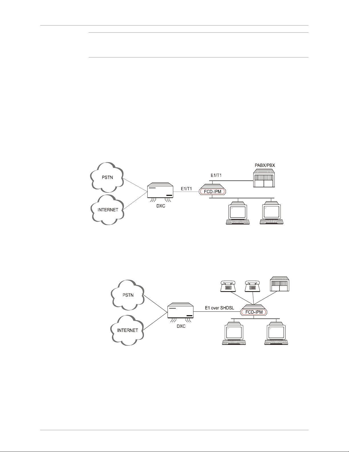
Applications
FCD-IPM is the solution for several different applications. Order your unit
according to your specific application requirements. FCD-IPM can be used as a
router for the office LAN to access the Internet/Intranet and at the same time
control access from the local PBX to the E1/T1 line. FCD-IPM can also have up to
twelve telephones connected directly to the unit for those applications where a
PBX is not present. The following is a list of application options for
FCD-IPM:
• FCD-IPM with PBX and LAN - In the application shown in Figure 1-1,
FCD-IPM supports a single LAN connection to the Internet/Intranet and voice
connectivity to the PSTN.
VOICE
LAN
LAN
Figure 1-1. FCD-IPM with PBX and LAN
• FCD-IPM with four Telephones and LAN – In the application shown in
Figure 1-2, FCD-IPM supports four individual telephones connected to the
carrier, and a LAN connection to the Internet/Intranet.
PABX/PBX
x4 x4
VOICE
LAN
FXS
FXS
Figure 1-2. FCD-IPM with Eight Telephones and LAN over SHDSL
Overview 1-3
Page 24

Chapter 1 Introduction FCD-IPM Installation and Operation Manual
Features
E1/T1 Main Link
• E1/T1 Integrated Access Device (IAD) for Internet/Intranet and voice connectivity
• E1 over 2-wire SHDSL link optional
• Integral E1 with or without LTU or Integral T1 CSU/DSU
• Optional sub-E1/T1 drop and insert port for PABX connectivity
• Fail-safe bypass for the sub-E1/T1 link
• Optional fiber optic uplink.
Integrated Router
• IP and IPX routing and standard bridging
• Supports Frame Relay, PPP and MLPPP
• One or two Ethernet ports or one Fast Ethernet port
• Optional dial-up or integrated ISDN backup
• PAP/CHAP authentication
• Solid Firewall protection
• NAT and Single IP address translation
• DHCP server and relay
• OSPF Protocol
• Quick setup and configuration
• In-band and out-of-band remote management
• SNMP and Telnet support
• Dual management authorization levels (carrier/user)
• FLASH memory for software and parameter file downloading
• Remote software and parameter file download.
Ethernet/Fast Ethernet Switch
• Built-in 4-port switch with 1Mb buffer with Auto-polarity and auto-negotiation.
Data
• Optional second data port (transparent n x 64/56 or serial router port).
Voice
• Supports twelve analog voice channels
• PCM encoded, A-Law or µ-Law
• Optional interfaces: 2-wire FXS, 2-wire FXO, or 4-wire or 2-wire E&M.
1-4 Overview
Page 25
FCD-IPM Installation and Operation Manual Chapter 1 Introduction
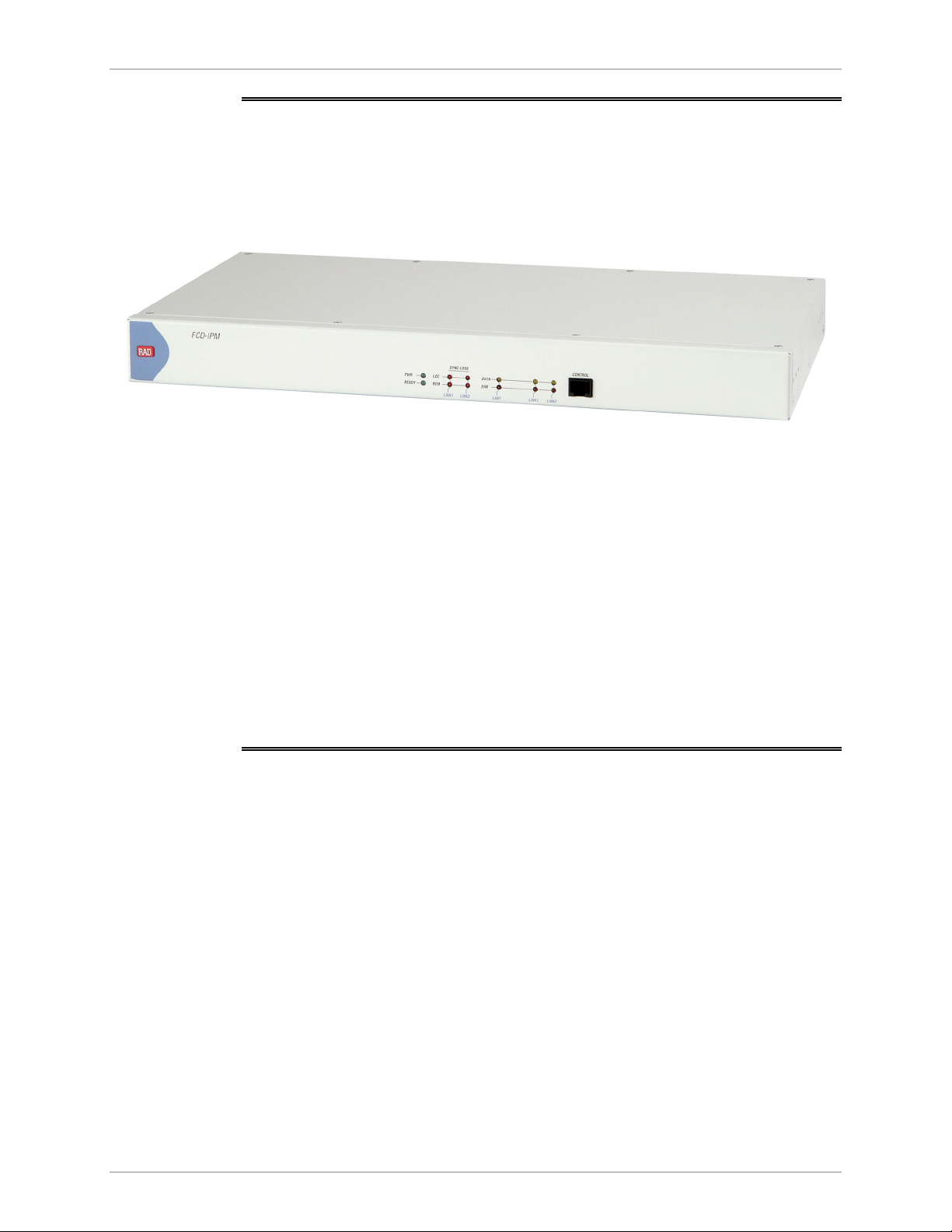
1.2 Physical Description
FCD-IPM units are delivered completely assembled. The units are designed for
desktop installation, or to be mounted in a 19-inch rack. Installation procedures
for FCD-IPM models and respective versions are provided in Chapter 2.
Figure 1-3 shows a 3-D diagram of FCD-IPM.
Figure 1-3. FCD-IPM General View
Controls and indicators of the various versions of FCD-IPM and their functions are
described in Chapter 3. The LED indicators on the front panel indicate the
operating status of FCD-IPM. Various indicators display status of user’s data port,
status of data activity in user’s data connector, and alert conditions. For a
description of the front panel, refer to Chapter 3.
The power and interface connectors are located on the rear panel of FCD-IPM.
For a description of the rear panel, refer to Chapter 2.
The internal jumpers of FCD-IPM are set according to options ordered. The only
jumper that you may need to set is the BAL/UNBAL jumper. The factory setting for
this jumper is BAL. For more information about setting jumpers, refer to Chapter 2.
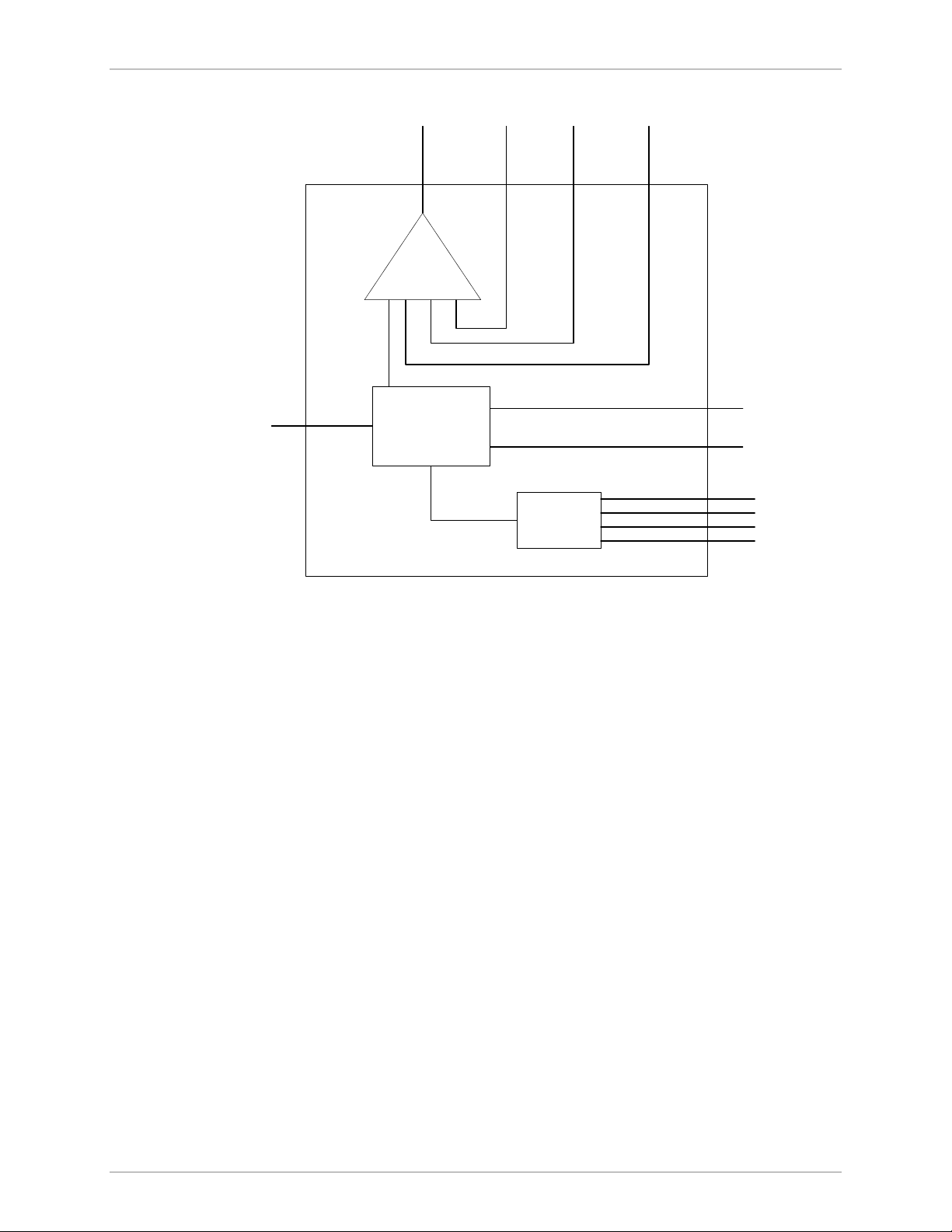
1.3 Functional Description
This section describes the main and sublink characteristics, the data and voice
channel interfaces, timing considerations, time slot handling, integrated IP router
and management of FCD-IPM. Figure 1-4 shows a functional block diagram for
FCD-IPM.
Functional Description 1-5
Page 26
Chapter 1 Introduction FCD-IPM Installation and Operation Manual
ISDN or
Serial
Port
Main
Link Sublink
Mux
Router
Voice
Port
Switch
n x 64 kbps
LAN 1
LAN 2
Figure 1-4. FCD-IPM Functional Block Diagram
FCD-IPM can be ordered in several configuration options. The main link is always
E1/T1 (E1 over SHDSL), and there is always at least one LAN link. The other
interfaces may be a sub E1/T1 link, analog voice, ISDN backup, n x 64 data port,
or router port.
Main Link and Sublink Characteristics
The FCD-IPM E1 main and sublink meet the requirements of ITU-T Rec. G.703,
G.704, G.706, G.732, and G.823, and support 256N and 256S multiframes
(2 or 16 frames per multiframe, respectively), in accordance with ITU-T Rec.
G.704. For FCD-IPM T1 versions the main and sublink comply to AT&T TR62411
and ANSI T1.403 standards, and support D4 and ESF framing.
The framed mode and use of the CRC-4 function are user-selectable.
1-6 Functional Description
Page 27

FCD-IPM Installation and Operation Manual Chapter 1 Introduction
The main and sublinks have two line interfaces:
• 120Ω balanced line interface, terminated in an RJ-48C eight-pin (ISO 10173)
connector
• 75Ω unbalanced interface, terminated in two BNC coaxial connectors
• T1 versions have a 100Ω balanced interface.
You can select the E1 interface to activate the LTU option. With the T1 version,
you can choose to activate CSU or DSU.
When a power failure occurs, the failsafe bypass of the sub E1/T1 link ensures the
continuity of voice services between the main and the fix sublink.
Note
The fail-safe bypass of the E1/T1 sub-link is not available for the FCD-IPM units
equipped with SHDSL interface.
E1 over SHDSL
E1 traffic can also be transmitted using 2-wire SHDSL physical interface. The
SHDSL link uses TC-PAM technology and complies with the requirements of the
ITU-T G.991.2 standard. Table 1-1 lists typical FCD-IPM ranges over 2-wire
24 AWG line.
Table 1-1. Typical FCD-IPM Ranges over SHDSL Link
Data Rate 2-wire, 24 AWG (0.5 mm)
kbps km miles
192
384
512
768
1024
1152
2048
IO Data Channel Interfaces
Each of the two IO data channels can be operated as n x 64k or n x 56k data port
(DCE only).
System Timing Considerations
Internally, FCD-IPM uses one system timing source (clock). This system clock
determines the transit timing of all the E1 links and data ports. The clock source
options are as follows:
6.5
5.8
5.1
4.8
4.1 2.5
3.5 2.1
3.2 1.9
4.0
3.6
3.1
2.9
• Main link 1
• Sublink (each of them)
• Internal.
Functional Description 1-7
Page 28

Chapter 1 Introduction FCD-IPM Installation and Operation Manual
Time Slot Handling
FCD-IPM allows the user to configure each of the individual time slots freely
according to the following options:
• Data link1 – for data from router/bridge
• FIX SUB Voice – for voice from sublink
• FIX SUB Data – for data from sublink
• FIX Voice (1, 2, 3, 4) – for analog voice port 1, 2, 3, 4
• I/O1 Voice (1, 2, 3, 4) – for analog voice port 1, 2, 3, 4
• I/O2 Voice (1, 2, 3, 4) – for analog voice port 1, 2, 3, 4
• I/O1 SUB Data – for data from sublink
• I/O2 SUB Data – for data from sublink
• I/O1 SUB Voice – for voice from sublink
• I/O2 SUB Voice – for voice from sublink
• I/O1 Channel – for n x 64/56 data port
• I/O2 Channel – for n x 64/56 data port.
For more information on configuring time slots, refer to Chapter 4.
Integrated Router
IP Router
FCD-IPM as an IP router supports:
• Static IP net configuration
• Dynamic IP net learning using RIP and RIP-2 protocols
• CIDR topologies
• Multiple IP nets on the LAN
• Numbered and unnumbered interfaces
• IP fragmentation
• RIP1, RIP2 & OSPF Routing Protocols.
IPX Router
FCD-IPM also supports standard IPX routing that includes support for RIP and SAP.
Bridging
FCD-IPM supports bridging. The bridge is used to interconnect a number of LANs
by accessing layer 2 (MAC layer). FCD-IPM automatically extends the scope of any
interface, allowing the interface to interconnect several networks, providing that all
supported interfaces are set to bridge mode.
1-8 Functional Description
Page 29

FCD-IPM Installation and Operation Manual Chapter 1 Introduction
FCD-IPM interconnects:
• Any LAN to link
• Two LANs of the same Bridge
• Two LANs and link.
FCD-IPM interconnects all of its interfaces to one extended LAN.
FCD-IPM supports standard bridging, as specified in IEEE 802.1D, and can operate
opposite any other third party bridge. Spanning Tree Algorithm is not supported.
Bridging works over PPP, Frame Relay RFC-1490 and also a ‘Native’ protocol.
MAC frames pass in an HDLC format.
Protocols
FCD-IPM supports:
• PPP (Point to Point Protocol) – this protocol supports a variety of links and
connection options
• Frame Relay – a network interface, which provides high-speed frame or packet
transmission with minimum delay and maximum bandwidth utilization.
Management
FCD-IPM features a variety of inband and out-of-band management options. These
options include dedicated time slot, dedicated DLCI, and dial-in connectivity.
You can manage the following capabilities:
• FCD-IPM configuration
• Viewing FCD-IPM status
• Testing FCD-IPM
• Viewing alarm status and history.
The management functions are performed via:
• SNMP management – enables management using the RADview or any other
standard SNMP-based management systems.
• Telnet – enables a remote IP host to control the operation of FCD-IPM using
functions identical to those provided by a supervision terminal.
• Supervision terminal – an ASCII terminal connected to the RS-232 control port
of FCD-IPM (or a PC running a terminal emulation program) can be used as a
supervision terminal.
Undesired access to FCD-IPM via Telnet or SNMP can be blocked by the firewall,
or password protected. The dual-level management authentication allows access to
router configuration parameters while restricting the access to network
configuration parameters.
Functional Description 1-9
Page 30

Chapter 1 Introduction FCD-IPM Installation and Operation Manual
Software download is available via the control port using XMODEM and via
LAN/WAN using TFTP. Parameter file download and upload is available via LAN or
WAN using TFTP.
FCD-IPM has an alarm history memory that holds the up to 100 alarms.
Management Using Dedicated Time Slot (DTS)
FCD-IPM features out-of-band management through a dedicated time slot.
The DTS is a management channel that connects directly to the FCD-IPM host
using a separate IP interface, i.e. address, and operates as an additional WAN
interface connected to the management IP network.
This management channel is totally separated from the IP traffic that the integrated
router forwards, so there is no way to expose the manager IP network to
unauthorized IP users.
The DTS channel should be synchronized with other equipment such as a cross
connect unit or router. This can be done with standard WAN protocols such as
Frame Relay and PPP.
1-10 Functional Description
Page 31

FCD-IPM Installation and Operation Manual Chapter 1 Introduction
1.4 Technical Specifications
E1 Link Interface
Framing Options
Bit Rate
Line Code
Zero Suppression
Line Impedance
Signal Levels
256N (no MF, CCS)
256N (no MF, CCS) with CRC-4
256S (TS16 MF, CAS)
256S (TS16 MF, CAS) with CRC-4
2.048 Mbps
AMI
HDB3
Balanced interface: 120Ω
Unbalanced interface: 75Ω
Receive level:
• FCD-IPM with LTU: 0 to –30 dB
• FCD-IPM without LTU: 0 to –12 dB
Transmit level:
• Balanced interface: ±3V ±10%
• Unbalanced interface: ±2.37V ±10%
T1 Link Interface
Jitter Performance
Connectors
Compliance
Diagnostics
Framing Options
Bit Rate
Line Code
Zero Suppression
Impedance
As per ITU-T Rec. G.823
Balanced interface: RJ-48c 8-pin connector
Unbalanced interface: Two BNC coaxial
connectors
ITU G.703, G.704, G.706, G.732
User activated local and remote loopbacks
D4
ESF
1.544 Mbps
AMI
Transparent
B7ZS
B8ZS
Balanced: 100Ω
Technical Specifications 1-11
Page 32

Chapter 1 Introduction FCD-IPM Installation and Operation Manual
Signal Level
Jitter Performance
Connectors
Compliance
Diagnostics
Receive level:
• FCD-IPM with CSU: 0 to –36 dB
• FCD-IPM without CSU: 0 to –10 dB
Transmit level:
• FCD-IPM with CSU: 0, -7.5, -15,
-22.5 dB
• FCD-IPM without CSU: soft adjustable at
0 to 655 ft.
As per AT&T TR-62411
Balanced interface: RJ-48c 8-pin connector
Unbalanced interface: two BNC coaxial
connectors
AT&T TR62411, ANSI T1.403
User available local and remote loopbacks
Network activated loops and FDL loops
(RLB, LLB)
SHDSL Interface
Analog Voice
Type
Line Coding
Range
Impedance
Connector
Protection
Number of Voice
Channels
Modulation Method
Interfaces
2-wire unconditioned dedicated line
TC-PAM
See Table 1-1
135Ω
RJ-45
ITU K.21, UL1950
4 per card
PCM (per ITU-T G.711 and AT&T
PUB-43801)
µ-Law or A-Law
E&M: 2-wire or 4-wire, supporting different
types of E&M signaling: RS-464 Types I, II,
III, and V, and BT SSDC5, configured by
software
FXS: Loop start, WINK start (reverse polarity)
for direct connection to a 2-wire telephone
1-12 Technical Specifications
Page 33

FCD-IPM Installation and Operation Manual Chapter 1 Introduction
FXO: Loop start, WINK start (reverse polarity)
for connection to a 2-wire telephone
exchange subscriber line
Nominal level: 0 dBm
Nominal impedance: 600Ω
Return loss (ERL): Better than 18 dB
Frequency response: (Ref: 1020 Hz)
• ±0.5 dB, 300 to 3000 Hz
• ±1.1 dB, 250 to 3400 Hz
Signal to total distortion, G.712, G.713
method 2:
• 0 to –30 dBm0, better than 33 dB
• +3 to –45 dBm0, better than 22 dB
Idle channel noise: Better than –70 dBm0
(+20 dBrnc)
Transformer isolation: 1500 VRMS
ISDN
WAN Protocols
Routing
Diagnostics
Interfaces
Compliance
Types
Types
Remote analog loopback towards the remote
side, activated from local side
1kHz tone injection towards analog side
Activity indicators
ISDN BRI, “S” and “U”
ETS 300012
I.430
NT1
5ESS
DMS-100
NI1
Frame Relay – RFC 1490
PPP and MLPPP
STATIC
RIP-1
RIP-2
RIP/SAP
OSPF
Technical Specifications 1-13
Page 34

Chapter 1 Introduction FCD-IPM Installation and Operation Manual
LAN Interface
Internal Ethernet/Fast
Ethernet Switch
Data Port Interfaces
Fiber Optic Interfaces
Number of Ports
Standards
Types
Interface
Number of Ports
Interfaces/Connectors
Interface Options
1 or 2
Conforms to Ethernet/IEEE 802.3
10Base2 with BNC coax connector
10BaseT with RJ-45 connector
10/100 BaseT
Four
V.35 with 34-pin female via adapter cable
V.24/RS-232 or RS-530 with 25-pin D-type
female
X.21 with 15-pin D-type female via adapter
cable
V.36/RS-422 with 37-pin D-type female via
adapter cable
850 nm LED
1300 nm LED
Indicators
Connectors
Compliance
1300 nm laser diode
1550 nm laser diode
ST
FC/PC
SC
ITU G.921, G.956
Power indicator (green)
Ready (green)
LINK (green)
100M (green)
LINK data (yellow)
LINK error (red)
RED alarm (red – T1 only)
YEL alarm (yellow – T1 only)
LOC sync loss indicator (red – E1 only)
REM sync loss indicator (red – E1 only)
1-14 Technical Specifications
Page 35

FCD-IPM Installation and Operation Manual Chapter 1 Introduction
General
Physical
Installation Kit
Power
Environment
Height
Width
Depth
Weight
Supply voltage
Power consumption
Temperature
Humidity
4.37 cm/1.7 in (1U)
44.0 cm/17.3 in
23.53 cm/9.25 in
5 kg/11 lb
RM-34 (for 19-inch Rack)
100–240 VAC, 50 to 60 Hz, 25 VA max
24/48 VDC
12W
0 to 50°C (32 to 122°F)
Up to 90%, non-condensing
Technical Specifications 1-15
Page 36

Chapter 1 Introduction FCD-IPM Installation and Operation Manual
1-16 Technical Specifications
Page 37

Warning
Chapter 2 Installation and Setup
This chapter provides instructions for mechanical and electrical installation of the
FCD-IPM unit.
After installation, you must configure the unit before further operation. Refer to
Chapter 4 for basic and advanced configuration instructions. In case a problem is
encountered, refer to Chapter 5 for test and diagnostics instructions.
No internal settings, adjustment, maintenance, and repairs may be performed
by either the operator or the user; such activities may be performed only by a
skilled technician who is aware of the hazards involved. Always observe
standard safety precautions during installation, operation, and maintenance of
this product.
Note
2.1 Site Requirements & Prerequisites
Install AC powered FCD-IPM units within 1.5m (5 feet) of an easily accessible,
grounded AC outlet capable of furnishing the nominal supply voltage, 115 or
230 VAC. DC powered units require a 24 or -48 VDC power source.
Allow at least 90 cm (36 inches) of frontal clearance for operator access. Allow at
least 10 cm (4 inches) clearance at the rear for interface cable connections. The
ambient operating temperature of FCD-IPM is 0° to 50°C (32° to 122°F), at a
relative humidity of up to 90%, non-condensing.
The FCD-IP units are cooled by free air convection therefore in rack installation it is
necessary to leave sufficient space (at least 1U) above and below each unit to
enable free airflow.
Site Requirements & Prerequisites 2-1
Page 38

Chapter 2 Installation and Setup FCD-IPM Installation and Operation Manual
2.2 Package Contents
Inspect the equipment package before unpacking. Note and report damage
immediately. The FCD-IPM package includes the following items:
• FCD-IPM unit
• Multiservice Access Devices and Intelligent CLEs CD
• CBL-RJ45/D9/F/6FT configuration cable
• Interface adapter cable in accordance with your order
• AC power cable or DC power connection kit.
2.3 Equipment Needed
The cables you need depend on the application. Cables terminated in appropriate
connectors provide support for the following data port interfaces:
• V.35 interface: the interface adapter cable ends in a 34-pin female connector
• V.36/422 interface: the interface adapter cable ends in a 37-pin D-type
female connector
• V.24/RS-232 or RS-530 interface: the interface adapter cable ends in a 25-pin
D-type female connector
• X.21 interface: the interface adapter cable ends in a 15 pin D-type female
connector.
2.4 Installation and Setup
The FCD-IPM units are delivered completely assembled. The units are designed
for desktop installation.
For installation of FCD-IPM in a 19-inch rack, the RM-34 rack mount kit is
available. For rack installation instructions, refer to the Rack Mounting Kit for
19-inch Racks guide that comes with the RM kit.
Installation procedures for FCD-IPM are provided in the following paragraphs.
Setting Internal Jumpers and Switches
Only the BAL/UNBAL jumpers, whose locations are shown in Figure 2-1, are
meant for user adjustment. All other internal jumpers are factory set according to
the specific ordering requirements and are not designed for user access. The
factory setting for the BAL/UNBAL jumpers is BAL. Before setting these jumpers,
open the FCD-IPM case.
2-2 Installation and Setup
Page 39

FCD-IPM Installation and Operation Manual Chapter 2 Installation and Setup
NO
FOR FLOATING
RX PATH
Fuses
YES
FOR
NON FLOATING
RX PATH
Factory Setting:
RX-G
NO
J4
NO
F-GND
YES
YES
YES
J1
J6
J3
UN
BAL
J7
J8
UN
BAL
Figure 2-1. Location of Internal BAL/UNBAL Jumpers
BAL UN
For E1 and T1 Interfaces - JUMPER J4
Factory Setting:
NO
Caution
The AC version of FCD-IPM has a user-replaceable fuse rated at 1A slow blow.
The fuse is accessible by opening the fuse cover located just above the power
connector on the rear panel.
Replace fuses only with fuses having identical ratings.
Installation and Setup 2-3
Page 40

Chapter 2 Installation and Setup FCD-IPM Installation and Operation Manual
2.5 Interfaces and Connections
Figure 2-2 shows a general diagram of the rear panels of AC-powered and
DC-powered FCD-IPM units, and identifies the different optional connector
locations.
Power
Connector
Options
AC
DC
P
O
W
E
R
Options
LAN 1
:
10/100BaseT
10Base2
LAN 2
:
Blank
10BaseT
10Base2
4-port Ethernet/
Fast Ethernet Switch
E1/T1 Link Connections
FCD-IPM E1/T1 link has a RJ-48c eight-pin connector for the balanced HDB3
interface, and two BNC connectors for the unbalanced HDB3 interface.
Appendix A provides the pin allocation for the RJ-48c connector.
Sub Link
Location
Data Port
Options
Blank
E1
T1
FXS
FXO
E&M
ISDN “U”
ISDN “S”
Options
Blank
V. 24
V. 35
X.21
V. 36
Rs530
Main Link Location
Figure 2-2. FCD-IPM Rear Panel
Options
E1
T1
SHDSL
IO Data Channel
IO Data Channel
Options
Blank
E1
T1
FXS
FXO
E&M
VXX
Ethernet Switch
Options
Blank
E1
T1
FXS
FXO
E&M
VXX
Ethernet Switch
Connect the E1/T1 link cables to the connector(s) corresponding to the interface in
use.
Caution
Do not connect to both the balanced and unbalanced connectors!
When using the balanced interface, connect to the RJ-45 connector.
When using the unbalanced interface, connect to the two BNC connectors
designated TX/Out and RX/In. Make sure the receive and transmit cables are
connected to the TX/Out and RX/In connectors properly.
IO Data Channel Connections
The FCD-IPM user data port has several possible interface connectors. A listing of
the connectors is given in Equipment Needed on page 2-2.
Connect the DTE link cable to the user data port connector. For more information
on pin allocation, refer to Appendix A.
2-4 Interfaces and Connections
Page 41

FCD-IPM Installation and Operation Manual Chapter 2 Installation and Setup
Control Port Connection
The FCD-IPM control port is located on the front panel. Connect the ASCII
terminal to this port. For more information on connecting to the control port, refer
to Connecting to the ASCII Terminal in Chapter 3.
Connecting the Power
For your protection, FCD-IPM must always be grounded. Any interruption of the
protective (grounding) conductor (inside or outside the instrument) or
disconnecting the protective earth terminal can make this instrument dangerous.
Intentional interruption is prohibited.
BEFORE POWERING UP AN AC POWERED FCD-IPM, the protective earth
terminals of this instrument must be connected to the protective conductor of
the (mains) power cord. The mains plug shall only be inserted in a socket
outlet provided with a protective ground (earth) contact. The protective action
Warning
must not be negated by use of an extension cord (power cable) without a
protective conductor (grounding).
Make sure that only fuses with the required rated current and of the specified
type, as marked on the FCD-IPM rear panel, are used for replacement. Use of
repaired fuses and short-circuiting of fuse holders is forbidden.
Whenever it is likely that the protection offered by fuses has been impaired,
the instrument must be made inoperative and be secured against any
unintended operation.
Warning
AC Power Connection
AC power should be supplied to FCD-IPM through the 1.5m (5 feet) standard
power cable terminated by a standard 3-prong plug.
To connect the AC power:
1. Check that the ON/OFF switch on the FCD-IPM rear panel is set to OFF.
2. Connect the power cable to the connector on the FCD-IPM rear panel.
3. Connect the power cable to the mains outlet.
DC Power Connection
To connect the DC power:
1. Check that the ON/OFF switch on the FCD-IPM rear panel is set to OFF.
2. Connect the power cable to the DC power connector.
Constraints
Do not hot swap the FCD-IPM modular IO data channel cards. A card must be
added to or removed from an IO slot when the power is off ONLY.
Interfaces and Connections 2-5
Page 42

Chapter 2 Installation and Setup FCD-IPM Installation and Operation Manual
2-6 Interfaces and Connections
Page 43

Chapter 3 Operation
In this chapter you will find detailed operating instructions for FCD-IPM. It
includes:
• Description of indicators
• Operating procedures (turn-on, front-panel indications, and turn-off)
• Connection to ASCII terminal
• Login.
Refer to Chapter 6 for diagnostic and troubleshooting instructions.
3.1 Introduction
FCD-IPM is designed for unattended operation. After initial power-up, and prior to
use, you must configure a basic set-up for FCD-IPM. For more information about
configuration, refer to Chapter 4.
3.2 Indicators
Front Panel Indicators
Figure 3-1 shows the location of front panel indicators for one of the various
FCD-IPM versions.
Table 3-1 lists the functions of the controls and indicators located on the front
panel of FCD-IPM.
Figure 3-1. FCD-IPM Front Panel
Indicators 3-1
Page 44

Chapter 3 Operation FCD-IPM Installation and Operation Manual
Table 3-1. Front Panel Indicator Functions
Object Description Function
POWER Green LED ON when FCD-IPM is powered on.
READY/LOOP Green LED ON when packets can be transferred.
Blinks – a loopback is active on E1, T1 or SHDSL link
LAN 1 DATA
LAN 2 DATA
LAN 1 ERR
LAN 2 ERR
LINK 1 DATA
LINK 2 DATA
LINK1 ERR
LINK2 ERR
LINK1 RED
ALARM
SUB RED
ALARM
LINK1
YELLOW
ALARM
Yellow LED ON when a packet is received or transmitted on the
LAN side.
Red LED ON when a LAN interface indicates an error.
Yellow LED Turns ON briefly when a packet is received or
transmitted on the LINK side.
Red LED OFF when there is a physical connection and no LINK
interface error.
Turns ON briefly when LINK interface indicates an
error.
Continuously ON when there is no physical connection.
Red LED ON when T1 link is in RED ALARM.
Local unit lost frame synchronization for more than
2.5 consecutive seconds.
Red LED ON when one of the T1 sub link is in RED ALARM.
Sub link of the local unit lost frame synchronization for
more than 2.5 consecutive seconds.
Yellow LED ON when one of the T1 sub link is in YELLOW ALARM.
Yellow alarm signal is sent from Remote Unit to inform
the local unit that a RED ALARM exists at the remote
end.
SUB YELLOW
ALARM
Yellow LED ON when one of the T1 sub link is in YELLOW ALARM.
Yellow alarm signal is sent from Remote Unit to inform
the sub link of the local unit that a RED ALARM exists at
the remote end.
LINK1 LOC
SYNC LOSS
Red LED ON when E1 link is in local sync loss alarm.
Local unit lost frame synchronization for more than 2.5
consecutive seconds.
SUB LOC
SYNC LOSS
Red LED ON when one of the E1 sub link is in local sync loss
alarm.
Sub link of the local unit lost frame synchronization for
more than 2.5 consecutive seconds.
3-2 Indicators
Page 45

FCD-IPM Installation and Operation Manual Chapter 3 Operation
Table 3-1. Front Panel Indicator Functions (Cont.)
Object Description Function
LINK1 REM
SYNC LOSS
SUB REM
SYNC LOSS
Red LED ON when E1 link is in remote sync loss alarm.
Red LED ON when one of the E1 sub link is in remote sync loss
Rear Panel Indicators
Object Description Function
LINK Green LED ON – LAN is connected to LAN1 or LAN2 connector or
100M Green LED ON – LAN speed is 100M
Remote sync loss signal is sent from Remote Unit to
inform the local unit that a sync loss exists at the remote
end.
alarm.
Remote sync loss signal is sent from Remote Unit to
inform the sub link of the local unit that a sync loss
exists at the remote end.
Table 3-2. Rear Panel Indicator Functions
to one of the Ethernet/Fast Ethernet switch ports.
OFF – LAN speed is 10M
3.3 Operating Instructions
Turning On
In order for the unit to function, you must provide FCD-IPM with a setup
configuration. You configure the unit after the initial power-up stage.
To turn on FCD-IPM:
• Set the power switch on the rear panel to ON.
FCD-IPM is now ready for configuration. Refer to Chapter 4, for quick setup and
advanced configuration instructions.
Normal Indications
During normal operation the POWER indicator lights up, and the READY indicator
lights up when packets can be transferred. Additional indications are:
• The LAN DATA indicator lights when a packet is received or transmitted on
the LAN side
FCD-IPM performs a self-test. All the FCD-IPM indicators should light up.
Confirm that all are operating. Following the test, all indicators except PWR
and READY turn off.
Operating Instructions 3-3
Page 46

Chapter 3 Operation FCD-IPM Installation and Operation Manual
• The LINK DATA indicator lights when a packet is received or transmitted on
the LINK side.
3-4 Operating Instructions
Page 47

FCD-IPM Installation and Operation Manual Chapter 3 Operation
Fault Indications
If a fault occurs, the following alarm indicators light up, and data transfer may be
interrupted:
• LAN ERR indicator lights when LAN interface indicates an error
• LINK ERR indicator lights when LINK interface indicates an error
• RED ALARM indicator lights when T1 interface detects red alarm
• YELLOW ALARM indicator lights when T1 interface detects yellow alarm
• LOC SYNC LOSS indicator lights when the E1 interface detects local sync loss
• REM SYNC LOSS indicator lights when the E1 interface detects remote sync
loss.
To obtain additional information, observe the state of the other indicators and
then refer to Chapter 6 for troubleshooting information:
Turning Off
Set the FCD-IPM power switch, on the rear panel of the unit, to OFF.
3.4 Connecting to the ASCII Terminal
FCD-IPM features a setup program that is invoked and run from an ASCII terminal
or a PC emulator. The terminal/terminal emulator is connected to the RJ-45
CONTROL port on the FCD-IPM front panel (see Figure 3-2).
Connecting the Terminal Emulator
To connect the terminal emulator:
1. Attach the cable to the RS-232 port on the PC.
2. Attach the other end of the cable to the CONTROL port on the FCD-IPM front
panel.
Connecting to the ASCII Terminal 3-5
Page 48

Chapter 3 Operation FCD-IPM Installation and Operation Manual
Figure 3-2. Connecting to Terminal Emulator
To setup the terminal:
1. Set the terminal to work at a baud rate of 9.6 kbps, No Parity, 8 Data Bits.
2. Set the hardware control to OFF.
3. Switch on FCD-IPM.
The operational screen is displayed.
To initiate the login message:
• Press <Enter> several times.
Password Protection
Using a password prevents unauthorized personnel from changing configuration
parameters.
Before you can access any configuration menus you will be prompted for login.
To logon:
• Enter the correct password. The factory default password is 1234.
The password can be changed or removed during configuration. For more
information, refer to Chapter 4.
Notes
1. Use of Password protection for the configuration module is recommended.
Always use the Exit option in the Main Menu once the unit has been
configured. Using the Exit option will force personnel requiring access to the
configuration module to use password.
2. Password verification is case sensitive. Once the password is set, use the same
case that you used when typing in the password.
3. To enable E1/T1 parameter configuration the supervisor password must be
used. Using the login password disables E1/T1 menu viewing.
3-6 Connecting to the ASCII Terminal
Page 49

Chapter 4 Configuration
Topics covered in this chapter include:
• Overview of configuration menus
• Main menu
• Quick setup menu
• Security menu
• Advanced setup menu
Download software/upload device parameters
• View menu
• Diagnostic tools menu.
4.1 Overview
The Main Menu has the following options:
• Quick setup menu – The Quick Setup menu is used to define the basic
parameters for your FCD-IPM unit. The Quick Setup menu allows you to
adjust setup and link configuration parameters while FCD-IPM is in operation.
Line-by-line prompts guide you throughout the procedure. On-screen
instructions and explanations guide you through the setup procedure. For a
complete description of the Quick Setup menu refer to Section 4.3.
• Security setup menu – Use the options in the Security Setup menu to control
FCD-IPM management and entry to your LAN by unauthorized users (refer to
Section 4.4).
• Advanced setup menu – The Advanced menu lists FCD-IPM configuration
parameters and their current values. You can change these parameters and
perform advanced configuration operations, not available through the Quick
Setup menu. Resetting the device and software downloads are also performed
via the Advanced Menu (refer to Section 4.5).
• View menu – Use the options in the View menu to view configuration screens
and information on interface connections, routing tables and statistics.
• Diagnostic Tools menu – Use the Diagnostic Tools menu to verify WAN and
LAN connectivity. The Ping feature allows you to request another user on the
LAN or WAN. If the remote user replies, connectivity is confirmed up to and
including the IP level.
Overview 4-1
Page 50

Chapter 4 Configuration FCD-IPM Installation and Operation Manual
• Exit – Select this option to return to the Operational Status Messages screen. In
this mode you can view real-time information about the unit’s activities.
4.2 Main Menu
Figure 4-1 shows the Main Menu options.
The name of the device connected to the terminal (FCD-IPM) is listed at the top of
the screen.
To choose an option from the Main Menu:
Type the number preceding the option.
MAIN MENU (Device name - FCD-IPM)
----------
1. Quick setup
2. Security setup
3. Advanced setup
4. View
5. Diagnostic tools
0. Exit
Press number to select or ESC to return to the previous menu
Figure 4-1. FCD-IPM Main Menu
4.3 Quick Setup Menu
The parameters listed on the Quick Setup Menu include most of FCD-IPM's
internetworking features:
• WAN Interface
• IP Parameters
• Physical connections
• Protocol
• Routing type.
The Quick Setup screen presents messages that prompt you to accept or modify
the current parameters. The parameter options are enclosed in brackets [ ].
To access the Quick Setup Menu:
1. In the Main menu, press 1.
The Quick Setup menu appears, showing the first parameter, Link Status.
To accept the current parameter:
• Press <Enter>.
4-2 Quick Setup Menu
Page 51

FCD-IPM Installation and Operation Manual Chapter 4 Configuration
To view the options:
• Toggle with the space bar and press ENTER.
To enter new information:
1. Type in the new parameters.
2. Press <Enter>.
To change the existing value:
• Press <Backspace>.
After all parameters have been accepted or changed, you can view them on the
screen. A confirmation message appears requesting that you confirm all the setup
changes. The device may reset after saving these changes.
To configure the setup parameters:
1. From the Main Menu, select option 1, Quick Setup.
2. Follow the on-screen instructions to accept or modify the setup parameters.
3. Press Y to save the setup parameters.
Quick Setup Parameters
The Quick Setup menu contains both general parameters and those parameters
specific to the interfaces installed. This section organizes the parameters into
various categories. The screen for each interface and a description of the options
in the Quick Setup menu can be found in the sections that follow. Refer to the
section that applies to the interface you ordered.
Quick Setup Menu 4-3
Page 52

Chapter 4 Configuration FCD-IPM Installation and Operation Manual
Table 4-1. Quick Setup Parameters
Parameters Type Options
WAN Parameters General Link status
Link mode
Routing
Protocol
WAN IP Address (for IP Router
only)
WAN IP Mask (for IP Router only).
E1/T1 E1/T1 Configuration
Frame Relay DCLI number
ISDN Protocol (ISDN)
Bandwidth
Connection Type
Channel A – Destination Phone No.
Channel B – Destination Phone No.
Connection.
V24 Async Modem Type
Baud Rate
LAN Parameters General LAN Status
LAN IP Address
LAN IP Mask
Default Gateway
Default Gateway Interface
Routing
Security
Parameters
Password
Security Type
Device Access Name
The Quick Setup Menu varies according to the options of FCD-IPM that you have
ordered. The following pages illustrate some of the Quick Setup menus that are
available.
The fields in the Quick Setup screens are described below.
4-4 Quick Setup Menu
Page 53

FCD-IPM Installation and Operation Manual Chapter 4 Configuration
Quick Setup Menu Examples
The following pages illustrate some of the Quick Setup menus, dependent upon
the interface that has been ordered.
Quick Setup for T1 (PPP, IP)
Figure 4-2 shows the Quick Setup menu for T1.
QUICK SETUP
-----------
WARNING: This device automatically exits to Operational
Messages 10 minutes after last keyboard action without
saving parameters
'ENTER' - Accept parameter , 'SPACE' - Change parameter.
WAN interface Link 1 - T1
Link status : [Enable]
Link mode : [Synchronous]
Routing : [IP ROUTER], Protocol: [PPP]
WAN IP address : 10.0.0.1, enter new : 10.0.0.1
WAN IP mask : 255.255.255.252, enter new: 255.255.255.252
Do you want to configure the T1 Interface parameters (Y/N)?:
Host IP setup:
LAN Status : [Enable]
LAN IP address : 192.168.1.1, enter new : 192.168.1.1
LAN IP mask : 255.255.255.000, enter new : 255.255.255.000
Default gateway setting by: [Interface]
Default gateway interface: 1
SECURITY Setup
Device access name : FCD-IPM
No password at present – do you want to create password (Y/N)?: [N]
Security type : [Disabled]
Saving the changes might cause RESET the unit.
Do you want to save QUICK SETUP (Y/N)? Y
Figure 4-2. T1 Interface Quick Setup Screen
Quick Setup Menu 4-5
Page 54

Chapter 4 Configuration FCD-IPM Installation and Operation Manual
Quick Setup for E1 (PPP, IP) + ISDN (Backup, 128K, PPP, IP)
Figure 4-3 shows the Quick Setup menu for E1.
QUICK SETUP
-----------
WARNING: This device automatically exits to Operational
Messages 10 minutes after last keyboard action without
saving parameters
'ENTER' - Accept parameter , 'SPACE' - Change parameter.
WAN interface Link 1 - E1
Link status : [Enable]
Link mode : [Synchronous]
Routing : [IP ROUTER], Protocol: [PPP]
WAN IP address : 10.0.0.1, enter new : 10.0.0.1
WAN IP mask : 255.255.255.252, enter new: 255.255.255.252
Do you want to configure the E1 Interface parameters (Y/N)?:
WAN interface Link 2/CH1 – BRI
Link status : [Backup] to interface: [LINK 1]
Routing : [IP ROUTER], Protocol: [PPP]
WAN IP address : 0.0.0.0, enter new : 0.0.0.
Protocol : [ETSI]
Bandwidth : [128]
Connection Type : [Originate only]
Channel A – Destination phone number: 1234
Channel B – Destination phone number: 5678
Connection : [Always]
Host IP setup:
LAN Status : [Enable]
LAN IP address : 192.168.1.1, enter new : 192.168.1.1
LAN IP mask : 255.255.255.000, enter new : 255.255.255.000
Default gateway setting by: [Interface]
Default gateway interface: [LINK 1]
SECURITY Setup
Device access name : FCD-IPM
No password at present – do you want to create password (Y/N)?: [N]
Security type: [Disabled]
Saving the changes might cause the unit to RESET.
Do you want to save QUICK SETUP (Y/N) ? N
Figure 4-3. E1 Interface Quick Setup Screen
4-6 Quick Setup Menu
Page 55

FCD-IPM Installation and Operation Manual Chapter 4 Configuration
WAN Settings
Set this parameter for the WAN configuration.
Table 4-2. WAN Parameters
Parameters Possible Values Description
Link Status
Link Mode
Routing
Enable
Disable
Backup
Synchronous
Frame Relay
Asynchronous
IP, IPX, Bridge
Any combination
of these link
types.
Transmits and receives frames.
Does not transmit or receive frames. The link may be permanently disabled, for
example, when testing. A disabled line freezes all link operation, including
connection attempts and forwarding.
If a link is defined as backup to another, then whenever the main link operates
normally, the backup link is disabled. If the main link fails, the backup link begins
to operate and become enabled. You must make sure that the routing settings are
correct so that traffic will be forwarded to the desired destination via the backup
link. When you restore the main link connection, the backup link becomes
disabled again.
Default : Enable
Data bits are transmitted at a fixed rate. The sender and the receiver are
synchronized
A packet-switching protocol for connecting devices on a WAN.
Data bits are transmitted at a fixed rate. The sender and the receiver are not
synchronized.
Assigns the link forwarding type.
Quick Setup Menu 4-7
Page 56

Chapter 4 Configuration FCD-IPM Installation and Operation Manual
Table 4-2. WAN Parameters
Parameters Possible Values Description
Protocol
PPP
RFC-1490
Point to Point Protocol. PPP consists of 3 components:
Encapsulation method – for IP datagrams on a serial link PPP supports HDLC
synchronous links.
LCP – Link control procedure to establish, configure, and test the data-link
connection. Having an LCP allows each end to negotiate various options.
NCP(s) – A family of network control protocols specific to different network layer
protocols. The NCPs allow each end to configure network control parameters.
PPP is often used across slow serial lines. It is therefore important to reduce the
number of bytes per frame in order to reduce the latency time. Using LCP, most
implementations negotiate to omitting the constant address and control fields and
reducing the size of the protocol fields from 2 bytes to 1 byte. In addition, when
using IP NCP, most implementations use Van Jacobson header compression to
reduce the size of IP and TCP headers.
Encapsulation method for carrying network interconnect traffic over a Frame
Relay backbone. RFC-1490 also supports a simple fragmentation procedure for
carrying large frames over a frame relay network with a smaller MTU.
DLCI – Every network interface card (NIC) has a Data Link Communication
Identifier (DLCI) that uniquely identifies the node on the network. DLCI enables
connection to the Frame Relay network without configuring Frame Relay
parameters.
DLCI executes congestion control when an explicit congestion notification is
received for the DLCI from the Frame Relay network. The unit reduces the
transmitted information rate of the DLCI and increases it when the congestion
condition is cleared.
Default : PPP
DLCI Number Sets the DLCI identification number.
4-8 Quick Setup Menu
Page 57

FCD-IPM Installation and Operation Manual Chapter 4 Configuration
LAN Settings
Set the parameters in this section for each LAN connection.
Table 4-3. LAN Parameters
Parameters Possible Values Description
LAN Status
Routing
LAN IP Address
Enable
Disable
Class A
1.0.0.0 to
127.255.255.255,
Class B
128.0.0.0 to
191.255.255.255,
Class C
192.0.0.0 to
223.255.255.255,
Class D
224.0.0.0 to
239.255.255.255
Class E
240.0.0.0 to
247.255.255.255
Transmits and receives frames
Does not transmit or receive frames. Used by system
administrator
Default : Enable
Select this parameter to set the routing option.
Note: This parameter appears for the 2-LAN device only.
Select this parameter to enter the IP address. Every device on
a TCP/IP network must have an identification address. The IP
address is a value consisting of the network address and the
host address on that network. The value assigned to a
network depends on the number of computers on that
network.
The IP address is a 32-bit number. The number consists of 4
parts, where each part consists of 3 digits. One part of the
address identifies the network and another part of the
address identifies the host. The numbers in the address,
which identifies the host, depend on the class.
There are 5 classes of IP addresses. Each class represents a
network having a certain number of computers. For example,
a Class C address is given to a network having between 1 to
255 computers.
The numbers in each part of the code are translated into
binary. The binary code identifies the network and the host.
IP addresses are assigned by the Internet Network
Information Center (InterNIC). InterNIC assigns the network
ID. Host IDs are assigned by the network administrator.
LAN IP Mask Select this parameter to enter the IP mask. The mask is
configured automatically from the IP address class. If you want
to change the default mask, enter a new mask. For example,
the IP mask is usually 225.225.225.0. A mask like this would
allow 254 hosts on the LAN. If you want to create a subnet,
which allows 6 users, including FCD-IPM, configure the mask
as 225.225.225.248. on FCD-IPM, as well as each host
included on the subnet (refer to Figure 4-4).
Quick Setup Menu 4-9
Page 58

Chapter 4 Configuration FCD-IPM Installation and Operation Manual
Table 4-3. LAN Parameters (Cont.)
Parameters Possible Values Description
Default Gateway
Setting
Select this parameter to set the Default Gateway configuration
(see Figure 4-4). The default gateway is the address to which
frames are sent, if no other address is defined in the routing
table.
The default gateway can be an IP address or a WAN interface.
If you choose to use an IP address, enter the address of the
router, which will deliver the frames. Specifying an IP address
for the default gateway is done with shared media, such as LAN
interface. If you choose to use a WAN interface, the connection
to the router is point-to-point. Choose by interface and enter
interface/DLCI number (for Frame Relay).
Warning: It is very important to obtain the correct parameters
from the system administrator or ISP. The most common
problem when establishing an IP connection is incorrect
configuration of the IP parameters and Default Gateway. Do not
try to guess these parameters.
E1/T1 Settings Prompts to perform advanced configuration on the main link
settings – E1 or T1, depending on your unit. By entering YES
you are sent into the Advanced Configuration menu. For more
information, refer to Chapter 5.
LAN IP address 192.1 68.1.1
Mask 255.255.255.248
FCD-IPM
IP address
Mask
Default Gateway
192.168.1.2
255.255.255.248
192.168.1.1
192.168.1.3
255.255.255.248
192.168.1.1
192.168.1.4
255.255.255.248
192.168.1.1
192.168.1.5
255.255.255.248
192.168.1.1
192.168.1.6
255.255.255.248
192.168.1.1
Figure 4-4. Setting up the IP Mask
4-10 Quick Setup Menu
Page 59

FCD-IPM Installation and Operation Manual Chapter 4 Configuration
ISDN Settings
FCD-IPM is available with ISDN “S” and “U” options.
Table 4-4. ISDN Settings
Parameters Possible Values Description
Protocol (ISDN)
Bandwidth 56, 64, 112, 128 kbps
Connection
Type
Destination
Phone Number
Assigns the protocol provided by the ISDN service in your
Answer only
Answer&Originate
Originate only
area. Some additional parameters may be requested
depending on the selected protocol.
Assigns a bandwidth. The bandwidth is the rate at which data
passes through the link. The greater the bandwidth, the more
information can be sent through the link. FCD-IPM allows
you to work with a bandwidth of 56, 64, 112, or 128 kbps.
Selection of 112 or 128 kbps for protocols other than IDSL
means MLPPP will be invoked.
Specifies the type of connection used to connect to the
Internet or Intranet.
If the link is to be used only for receiving incoming
connections
If the link is to be used for both incoming and out going
connections (not simultaneously)
If the link is to be used for outgoing connections only.
Defines the phone number used to connect to the Internet or
Intranet. To edit the phone number, erase the number with
the Backspace key and enter the new number. This
parameter appears only when the connection type is
Originate only or Answer&Originate.
Connection
Frame Relay Settings
You need to set the DCLI number, to allow connection to the Frame Relay
network without setting Frame Relay parameters.
DLCI Number
Select this parameter to set the DLCI number.
Determines when the link between the local LAN and the
Internet should be activated. Selecting any frame for
forwarding, activates the link only when there is traffic to be
sent on the link. Selecting Always keeps the link active,
independent of traffic. The Connection parameter is
important in reducing operating costs.
Quick Setup Menu 4-11
Page 60

Chapter 4 Configuration FCD-IPM Installation and Operation Manual
V.24 Async Settings
Two settings that must be made.
Table 4-5. V.24 Async Settings
Parameters Description
Modem Type Select this parameter to select the modem type.
Baud Rate Select this parameter to display the rate at which data is sent between FCD-IPM and
the modem. Use the Space Bar to toggle between the different baud rates. The Quick
Setup default value is recommended for your modem.
Security Settings
This feature provides protection from unauthorized access through the Internet.
Table 4-6. Security Settings
Parameters Description
Device Access
Name
Device Access
Password
Security Type Permits access to all users (disable) or restrict access to allow/deny users whose profiles
Display the name assigned to FCD-IPM for identification by the Internet Provider. To
change the device access name, type in the new name and press Enter.
Assign or updates a password. The password is used to access the Internet.
are defined (enable) in the system.
4-12 Quick Setup Menu
Page 61

FCD-IPM Installation and Operation Manual Chapter 4 Configuration
4.4 Security Setup Menu
Topics covered in this section include:
• Enabling Telnet access
• Enabling SMNP access
• Enabling/disabling the Solid Firewall
• Changing the login password
• IP Address translation (NAT).
Quick Setup
1
Security Setup
2
Advanced
3
Menu
5
View
Diagnostic
Tools
4
Device
Access
Restrictions
21 3
FIREWALL
Options
Figure 4-5. Security Setup Menu Outline
The Security Setup menu allows you to control access to FCD-IPM and access to
the LAN. FCD-IPM is protected against unauthorized user access by disabling
access via SNMP and TELNET. The Solid Firewall is used to protect the LAN
against undesired entry.
To access the Security Setup Menu:
1. In the Main menu, press 2.
The Security Setup menu appears (refer to Figure 4-6).
SECURITY SETUP ( Device name - FCD-IPM)
--------------
1. Device access restrictions
2. FIREWALL options
3. IP address translation
ESC - Return to previous menu
Choose one of the above:
IP Address
Translation
Figure 4-6. Security Setup Menu
The Security Setup options are described below.
Security Setup Menu 4-13
Page 62

Chapter 4 Configuration FCD-IPM Installation and Operation Manual
Device Access Restriction
Parameters listed on this screen allow you to control access to FCD-IPM
configuration from the control port or from LAN/WAN (via Telnet and SNMP).
Enabling Telnet Access
FCD-IPM supports Telnet. This allows FCD-IPM to be configured and controlled
over the WAN and LAN using TCP/IP.
Access to Telnet requires authentication by the device, using username and
password.
By default, Telnet access to FCD-IPM is disabled to prevent changes being made to
the unit's configuration parameters.
To enable Telnet access:
1. From the Security Setup menu, select option 1, Device Access Restrictions.
2. From the Device Access Restrictions menu, select option 1, TELNET Access
Status and change it to Enable.
3. Select options 2 and 3 to change the User name and Password, if required.
FCD-IPM can now be accessed using your TELNET username and password.
Enabling SNMP Access
By default, access to FCD-IPM via SNMP is disabled. Blocking SNMP access
prevents changes being made to the unit's configuration parameters.
To enable SNMP access:
1. From the Security Setup menu, select option 1, Devise Access Restrictions.
2. From the Devise Access Restrictions menu, select option 4, SNMP Access
Status and change it to Enable.
3. Select options 5, 6, and 7 to change Read, Write and Trap communities, if
required.
FCD-IPM can now be accessed for SNMP operation using the appropriate
communities.
Changing Login Password
Entrance to configuration screens, via terminal from the control port, is set by the
factory default as Protected by Password. The default password is 1234.
To change the password or remove password protection:
1. From the Security Setup menu, select option 1, Device Access Restrictions.
2. From the Device Access Restrictions menu, select option 8, Monitor User
Password.
3. Enter a new value for the Password.
4-14 Security Setup Menu
Page 63

FCD-IPM Installation and Operation Manual Chapter 4 Configuration
Supervisor Access
FCD-IPM has the option of dual–level password access. This allows certain menus
to be blocked from a regular user, while permitting a supervisor to access and alter
the parameters of these menus. To use this option, set a Monitor Supervisor
Password.
To set a Monitor Supervisor Password:
1. From the Security Setup menu, select option 1, Device Access Restrictions.
2. From the Device Access Restrictions menu, select option 9, Monitor
Supervisor Password.
Note
Leaving Password blank removes login protection.
Firewall Option
Solid Firewall is a rule-based security mechanism, which monitors incoming and
outgoing traffic and allows or restricts access according to the user-defined criteria
(rules).
You can configure the Solid Firewall to monitor incoming or outgoing traffic on any
WAN and LAN link. The firewall blocks all traffic coming from the unprotected
network segment to the protected section, and allows traffic from protected to
unprotected segments. Only those applications that are enabled via the application
list (e.g. HTTP, FTP, POP3 servers, etc.) are allowed for use. By default, the Solid
Firewall is disabled.
To select the Solid Firewall interface and direction:
1. From the Main menu, select option 2, Security Setup.
2. From the Security Setup menu, select option 2, Firewall Options.
The Firewall Setup menu appears (see Figure 4-8).
3. From the Firewall Setup menu, type 1.
The Firewall Interface menu appears (see Figure 4-9).
4. From the Firewall Interface menu, type A and define the link on which you
intend to set the firewall and traffic type to monitor:
Inbound – The firewall blocks the traffic coming into FCD-IPM via the link
on which the firewall is enabled. The firewall forwards the traffic going out
of the firewall-protected interface to its destination.
Outbound – The firewall blocks the traffic going out of FCD-IPM via the
link on which the firewall is enabled. The firewall grants access to the traffic
coming into FCD-IPM from the network segment attached to the
firewall-protected interface.
5. Press <Esc> and save new values.
Security Setup Menu 4-15
Page 64

Chapter 4 Configuration FCD-IPM Installation and Operation Manual
To define the Solid Firewall rules:
1. From the Firewall Setup menu, type 2.
The Firewall Rules menu appears (see Figure 4-10).
2. From the Firewall Rules menu, type A and perform the following:
Define a link on which the rule will be applied
Specify the source IP address range by defining the start and end addresses.
Specify the destination IP address range by defining the start and end
addresses.
Enable the application used by the rule (user defined, Telnet, Ping, HTTP,
FTP, TFTP, POP3, SMTP, SNMP, SNMP Trap, BOOTP/DHCP, DNS Client
to Server, or DNS Server to Server).
If you select a user-defined application, you must specify the following
parameters:
Protocol type: TCP, UPD or ICMP
Minimum and maximum port value for TCP and UDP protocols, or
ICMP message type for ICMP protocol.
3. Press <Esc> and save new firewall rule values.
For example, two LANs are connected to the FCD-IPM 10BaseT ports
(see Figure 4-7). LAN 1 includes company’s Web, mail and FTP servers, which
cab be accessed from the outside. Employees’ PCs sitting on LAN 2 must not
be reached from the outside, but they must be allowed to access the servers.
In order to grant access to LAN 1 and restrict it to LAN 2, you must set up two
firewalls:
Firewall 1
Select interface – main link
Select direction – inbound
Define rule 1 for Web server:
Start and end source IP address – 0.0.0.0 to 255.255.255.255
Start and end destination IP address – 192.111.111.111
Protocol – HTTP.
Define rule 2 for mail server, which is identical to rule 1, except for
destination IP addresses (192.111.111.112) and protocol (SMTP).
Define rule 3 for FTP server, which is identical to rule 1, except for
destination IP addresses (192.111.111.113) and protocol (FTP).
Firewall 2
Select interface – LAN 2
Select direction – outbound.
4-16 Security Setup Menu
Page 65

FCD-IPM Installation and Operation Manual Chapter 4 Configuration
Main Link
Firewall 2
Users
Inbound
FCD-IPM
Outbound
Figure 4-7. Configuring Firewalls
FIREWALL SETUP ( Device name - FCD-IPM )
--------------
1. FIREWALL Interfaces
2. FIREWALL Rules
Firewall 1
LAN 1LAN 2
Web Server
19 2. 111.111 .111192.110.110.0 192.111.111.112 192.111.111.113
Mail Server FTP Server
ESC - Return to previous menu
Choose one of the above:
Figure 4-8. Firewall Setup Menu
FIREWALL INTERFACES ( Device name - FCD-IPM )
-------------------
Interface Direction
OPTIONS: A-Add
Press one of the above or ESC to return to previous screen:
Select interface: [LINK 1 ]
Select Direction: [Inbound ]
Figure 4-9. Firewall Interfaces Menu
Security Setup Menu 4-17
Page 66

Chapter 4 Configuration FCD-IPM Installation and Operation Manual
FIREWALL RULES ( Device name - FCD-IPM )
--------------
Interface Direction
OPTIONS: A-Add
Press one of the above or ESC to return to previous screen:
Select interface: [LINK 1 ]
Enter start source IP address: 000.000.000.000
Enter end source IP address : 222.222.222.222
Enter start destination IP address :
Enter end destination IP address :
Select application type: [Telnet ]
Figure 4-10. Firewall Rules Menu
IP Address Translation (NAT)
IP Address Translation allows a NET that uses a private IP Address to connect to
the Public Internet/Intranet (Single IP is one of the IP Address Translation types).
IP ADDRESS TRANSLATION (Device name – FCD-IPM)
----------------------
Type Interface Status Range
OPTIONS: A-Add
Press one of the above or ESC to return to previous screen:
Figure 4-11. IP Address Translation Menu
Pubic Internet/
Intranet
FCD-IPM
"Real IP Addresses"
...
PC#1
PC#2
"Virtual IP Addresses"
PC#n
Figure 4-12. IP Address Translation
4-18 Security Setup Menu
Page 67

FCD-IPM Installation and Operation Manual Chapter 4 Configuration
IP Address Translation permits some, or all, PCs on your private LAN to be
represented with legal IP Addresses that are defined on the internet/Intranet (refer
to Figure 4-12).
FCD-IPM supports the IP Address Translation types listed in Table 4-7.
Table 4-7. IP Address Translation (NAT) Settings
Parameters Description
Static Single
Static Range
Concurrent
Transparent
PAT (Port
Address
Translation)
Single IP
A PC with its Virtual Address specified will have access to the Internet/Intranet with a legal,
real IP Address. Bidirectional one-to-one access is allowed.
PCs with their Virtual Addresses within the specified range will have access to the
Internet/Intranet with a legal, real IP Address range. Bidirectional N-to-N access is allowed.
A number of PCs (n) with their Virtual Addresses within the specified range will have access,
but only some of them (m) can work simultaneously (m<n). The application must be started
from the private LAN.
Address translation is not performed for a specified range of IP Addresses. This setup may be
used for the application shown in
Figure 4-13.
FCD-IPM connects a UDP or TCP port to a specified IP address. PAT is available for single IP
only.
The whole Private LAN is represented as a single legal IP Address on Internet/Intranet.
Pubic Internet/
Intranet
Note
FCD-IPM
...
PC#1 PC#2 PC#n
Servers with Legal IP Addresses
for Outgoing Services
Figure 4-13. IP Address Transparent
For Static and Concurrent Address Translation, all PCs on your LAN with IP
Addresses not covered by the listed definitions will not obtain access to the
Internet/Intranet.
You may enter more than one entry of each type.
Each definition in a list may be Enabled or Disabled separately.
Security Setup Menu 4-19
Page 68

Chapter 4 Configuration FCD-IPM Installation and Operation Manual
4.5 Advanced Setup Menu
The Advanced Menu contains the majority of FCD-IPM configuration parameters.
You can change these parameters and perform advanced configuration operations
that are not available through the Quick Setup menu. Resetting FCD-IPM and
software downloads are also performed via the Advanced Menu.
Advanced Menu
1
Setup
2
Device Control
Figure 4-14. Advanced Menu Outline
To access the Advanced Menu:
• In the Main Menu, press 3.
The Advanced Menu appears (refer to Figure 4-15).
ADVANCED MENU (Device name - FCD-IPM)
-------------
1. Setup
2. Device control
ESC - Return to previous menu
Choose one of the above:
Figure 4-15. Advanced Menu
The options in the Advanced Menu are:
• Setup - used to modify setup parameters
• Device Control - used to download the software and parameters, and perform
reset operations.
These options are described in the sections below.
Setup Menu
Refer to Chapter 5 for a detailed description of this option.
4-20 Advanced Setup Menu
Page 69

FCD-IPM Installation and Operation Manual Chapter 4 Configuration
Device Control Menu
Advanced Menu
1
Software
Download
1. Download
from TFTP
Server
2. XMODEM via
Control Port (BOOT
Manager)
2
Upload Device
Parameters to
TFTP Server
3
Download Device
Parameters from
TFTP Server
Figure 4-16. Device Control Menu Outline
To access the Device Control menu:
• In the Advanced Menu, press 2.
1
2
Setup
Device Control
4
Reset Options
1. Reset Device
2. Reset Li nk
3. Reset Interface
Module
5
Terminal Type
1. VT-100, VT-200,
VT-220 ANSI
Terminals
2. VT-52, IBM 3101
Terminals
3. Other Terminals
The Device Control menu appears (refer to Figure 4-17).
DEVICE CONTROL (Device name - FCD-IPM)
--------------
1. Software download
2. Upload device parameters to TFTP server
3. Download device parameters from TFTP server
4. Reset options
5. Terminal type
ESC - Return to previous menu
Choose one of the above:
Figure 4-17. Device Control Menu
The options in the Device Control menu are described below.
Advanced Setup Menu 4-21
Page 70

Chapter 4 Configuration FCD-IPM Installation and Operation Manual
Software Download
Select this option to download a new software version.
SOFTWARE PARAMETERS IN THE DOWNLOAD (Device name-FCD-IPM)
-----------------------------------
1. Download from TFTP Server
2. XMODEM via control port (BOOT Manager)
3. Download software to ISDN module
ESC - Return to previous menu
Choose one of the above:
Figure 4-18. Software Download Menu
FCD-IPM includes a Dual Image Flash, capable of storing two different versions of
software in two different partitions.
Upon reset (or boot, refer to Appendix D), FCD-IPM automatically runs the
program stored in the active partition.
New software versions are loaded into the backup partition. If loading succeeds,
the backup partition becomes active and reset is automatically performed, running
the new software version. If loading fails, however, the device will still be capable
of working, since the Flash partition storing the old version is still active. Refer to
Figure 4-19.
Step 1
Original
S/W Version
Copy 1
Active Partition Backup Partition
Original
S/W Version
Copy 2
Original
S/W Version
Active Partition Backup Partition
Step 2
New
S/W Version
Step 3
Original
S/W Version
Backup Partition Active Partition
Figure 4-19. Using the Dual Image Flash
New
S/W Version
4-22 Advanced Setup Menu
Page 71

FCD-IPM Installation and Operation Manual Chapter 4 Configuration
Control Dual Image Flash by the BOOT Manager. You use the BOOT Manager to
manually define active and backup partition, run backup partition, erase some or
all information from Flash etc. The BOOT Manager is accessible via the above
menu or immediately after resetting the hardware. Refer to Appendix C for a
detailed description of the BOOT Manager.
The options in the Software Download menu are described below.
Download from TFTP Server
TFTP is an IP/UDP client-server application. The unit is a TFTP client. Operating
opposite the client, you need a TFTP server connected to the LAN or WAN
interface via an IP network.
TFTP Server
File
Transf er
TFTP C lient
FCD-IPM
IP Address: 192 .168.10.11
Stores file at C:\booting\boot.exe
Figure 4-20. Downloading from a TFTP Server
To download a new software version via TFTP server:
1. Select option 1 from the Software Download menu.
Do you want to download new software version? (y/n): Y
TFTP server IP address: 192.168.182.34
New software file name: fcdipm.mbi
Download process will erase the program code
in the second partition of the device.
Upon completion of the download,
the device will be reset automatically.
Press 'S' to start the download process
or
ESC to return to previous menu:
Figure 4-21. Software Download Menu
2. Confirm that the Do You Want To Download New Software Version field is
set to Yes.
3. In the TFTP Server IP Address field, type the IP address of the TFTP server.
Advanced Setup Menu 4-23
Page 72

Chapter 4 Configuration FCD-IPM Installation and Operation Manual
4. In the New Software File Name field, type the path and file name of the new
software version.
Note
The IP address and the new software version file name can also be defined through
the Setup menu. Refer to Setup at the beginning of the chapter.
5. Press S to start the download process.
During the process, the new program code is downloaded to the Flash backup
partition, thus erasing its previous contents.
Upon completion, the newly downloaded Flash partition becomes active,
while the old version’s partition becomes backup. The device automatically
resets, running the new program stored in the active partition.
During the download process, a counter shows the number of packets that have
passed. Downloading can be interrupted at any time by pressing the ESC key.
XMODEM via Control Port (BOOT Manager)
Use this option to access the BOOT Manager via the control port. Refer to
Appendix B for more information on the Boot Manager.
Upload Device Parameters to TFTP Server
Select this parameter to save device configuration parameters into a file by
uploading to the TFTP server. This operation sends all unit parameters to the TFTP
server and will be saved under a filename that you specify.
Parameter File Download/Upload
FCD-IPM
Figure 4-22. Downloading/Uploading Parameters
To upload device parameters:
1. Activate the TFTP server application connected to the unit via an IP network.
2. Configure the following IP parameters: IP address, IP mask and IP default
gateway.
3. Select the TFTP upload option.
4. Enter the TFTP server IP address.
5. Assign a name to the configuration file you want to save on the server, for
example V35_file.
IP
TFTP Server
6. Press S to start the upload process.
4-24 Advanced Setup Menu
Page 73

FCD-IPM Installation and Operation Manual Chapter 4 Configuration
Download Device Parameters from TFTP Server
Select this option to load device configuration parameters from a file by
downloading from the TFTP server.
To download device parameters:
1. Activate the TFTP server application connected to the unit via an IP network.
2. Configure the following IP parameters: IP address, IP mask and IP default
gateway.
3. Select the TFTP download option.
4. Enter the TFTP server IP address.
5. Enter the name of the configuration file you want to download from the server,
for example V35_file.
6. Press S to start the download process.
Note
Upon completion of the download process, the unit performs reset. The new
parameters only come into effect after resetting.
Reset Options
Select this option for resetting the device, link, or interface module.
Terminal Type
Select this option to choose a terminal type. Since each terminal type uses
different ASCII control codes for cursor control, FCD-IPM requires this information
to display the screens clearly. This setting affects the Statistics screen display only.
Advanced Setup Menu 4-25
Page 74

Chapter 4 Configuration FCD-IPM Installation and Operation Manual
4.6 View Menu
Use the View menu options to see information on interface connections, routing
tables, statistics, diagnostics, and alarms.
Quick Setup
1
Security Setup
2
Advanced Menu
3
View
4
Diagnostic Tools
5
7
1
Configuration
2
Interface
Connections
3
Routing
Tables
4
Statistics
5
E1/T1
Diagnostics
6
SHDSL
Status
E1/T1
Alarms
Log File
Link Number
Advanced Link
Configuration
1. Bridge
2. IP Interfaces
3. IP Routing
4. IPX Routing
5. IPX Services
6. ARP
7. OSPF Related
Information
8. IP Address
Pool
Figure 4-23. View Menu Outline
To access the View Menu:
• In the Main Menu, press 4.
The View Menu appears (see Figure 4-24).
The options in the View Menu are described in this chapter.
4-26 View Menu
Page 75

FCD-IPM Installation and Operation Manual Chapter 4 Configuration
VIEW MENU (Device name - FCD-IPM)
---------
1. Configuration
2. Interface Connections
3. Routing Tables
4. Statistics
5. SHDSL Status
6. E1/T1 Diagnostics
7. E1/T1 alarms log file
Press number to select or ESC to return to the previous menu:
Figure 4-24. View Menu
Configuration
Select this option to view the configuration parameters for the device and link that
were entered through the Setup menu. The View Configuration screen displays the
general unit configuration and parameters such as names, addresses and link types
(including link baud rate and status). When typing the interface number, detailed
information on the interface appears. Since these screens are “display-only” you
cannot use them to adjust parameters.
View Menu 4-27
Page 76

Chapter 4 Configuration FCD-IPM Installation and Operation Manual
VIEW CONFIGURATION (Device name - FCD-IPM)
------------------
Device type: FCD-IPM
Contact person : name of contact person
System location : the location of this device
Hardware version : 1.0 (1997-11-17)
Software version : 3.00 B1 (2003-03-11)
Burned-In MAC address : 0020 D217 5F61 (active)
Local Administered MAC address : 4020 D217 5F61
IP address : 10.10.90.1
Link Interface Type Clock(Kbps) Status Mode
----- ---------- ---------------- ----------- ------ ----
1) 1 SHDSL+SUB Synchronous Ext Link1/ 0 Enabled Bridge
2) 2 V.11 DTE Synchronous External/ 0 Enabled Bridge
--------------------------------------------------------------------------
I/O1: FXS
I/O2: FXS
ESC - Return to previous menu
For advanced link configuration information - enter link number:
Figure 4-25. View Configuration Screen
4-28 View Menu
Page 77

FCD-IPM Installation and Operation Manual Chapter 4 Configuration
Interface Connections
This screen displays the connection status for all FCD-IPM LAN and WAN
interfaces. The information includes physical connections like E1, subE1 V.35,
ISDN and logical connections like DLCIs in Frame Relay. Each row in the screen
shows the last successful channel synchronization.
INTERFACE CONNECTIONS (Device name – FCD-IPM)
---------------------
INTERFACE ROUTING DEVICE CONNECTED CONNECTION
TYPE NAME USER NAME STATUS
------------------------------------------------------------ LAN 1 Bridge + IP Close
LINK1 IP PPP LCP+IP/VJ
MANAGEMENT Mngmnt PPP LCP+IP
FIX SUB Local sync loss
IO1 Remote sync loss
IO2 Remote sync loss
R – Refresh
ESC – Return to previous menu
Figure 4-26. Interface Connections Screen
Routing Tables
Select this option to display different routing tables.
ROUTING TABLES (Device name - FCD-IPM)
--------------
1. Bridge
2. IP Interfaces
3. IP Routing
4. IPX Routing
5. IPX Services
6. ARP
7. OSPF
8. IP Address Pool
ESC - Return to previous screen
Figure 4-27. Routing Tables Menu
The options in the Routing Tables menu are described below.
View Menu 4-29
Page 78

Chapter 4 Configuration FCD-IPM Installation and Operation Manual
Bridge
Select this option to display a table that contains information on Bridge MAC
addresses (see Figure 4-28).
BRIDGE TABLE (Page-1) (Device name - FCD-IPM)
------------
MAC ADDRESS TYPE INTERFACE
----------- ---- ---------
0020D2FD5153 Static or Dynamic LAN
ESC - Return to previous menu
Figure 4-28. Bridge Table
IP Interfaces
Details the routing interfaces information.
IP INTERFACES TABLE (Page-1) ( Device name - FCD-IPM )
-------------------
IP ADDRESS IP MASK MTU PROTOCOL INTERFACE STATUS
--------------- --------------- ----- --------- ---------- ------
192.170.007.001 255.255.255.000 1500 --------- LAN 1 UP
000.000.000.000 000.000.000.000 1500 --------- LINK 1 UP
ESC - Return to previous menu
Figure 4-29. IP Interfaces Table
IP Routing
Select this option to display a table that contains information on IP routing.
IP ROUTE TABLE (Page-1) ( Device name - FCD-IPM )
IP ADDRESS IP MASK TYPE COST NEXT HOP AGEING INTERFACE
------------- --------------- ------ ---- --------------- -------- ---------default gateway LINK 1
192.170.007.000 255.255.255.000 INTRF 0 192.170.007.001 00:00:00 LAN 1
ESC - Return to previous menu
Figure 4-30. IP Routing Table
4-30 View Menu
Page 79

FCD-IPM Installation and Operation Manual Chapter 4 Configuration
IPX Routing
Select this option to display information on IPX routing.
IPX ROUTING TABLE (Page-1) (Device name - FCD-IPM)
-----------------
IPX NET IPX NODE TYPE HOPS TICKS AGEING INTERFACE
------- -------- ---- ---- ----- ------ ---------
0000000A 0000C0F5D899 NET (RIP) 1 2 00:00:50 LAN
0000001B 0000C0F5D899 NET (RIP) 4 5 00:00:50 LAN
0000001C 0000C0F5D899 NET (RIP) 3 4 00:00:50 LAN
0000001D 0000C0F5D899 NET (RIP) 3 4 00:00:50 LAN
0000001E 0000C0F5D899 NET (RIP) 3 4 00:00:50 LAN
0000001F 0000C0F5D899 NET (RIP) 1 2 00:00:50 LAN
0000001G 0000C0F5D899 NET (RIP) 3 4 00:00:50 LAN
0000001H 0000C0F5D899 NET (RIP) 3 4 00:00:50 LAN
0000002I 0000C0F5D899 NET (RIP) 3 4 00:00:50 LAN
0000002J 0000C0F5D899 NET (RIP) 3 4 00:00:50 LAN
0000003K 0000C0F5D899 NET (RIP) 3 4 00:00:50 LAN
0000006L 0000C0F5D899 NET (RIP) 3 4 00:00:50 LAN
0000009M 0000C0F5D899 NET (RIP) 2 3 00:00:50 LAN
0000012N 0000C0F5D899 NET (RIP) 3 4 00:00:50 LAN
0000067O 0000C0F5D899 NET (RIP) 3 4 00:00:50 LAN
0000083P 0000C0F5D899 NET (RIP) 3 4 00:00:50 LAN
ESC - Return to previous menu
Figure 4-31. IPX Routing Table
View Menu 4-31
Page 80

Chapter 4 Configuration FCD-IPM Installation and Operation Manual
IPX Services
Select this option to display a table that contains information on IPX services (SAP
table).
IPX SERVICES TABLE (Page-1) (Device name - FCD-IPM)
------------------
SERVER NAME TYPE IPX NET HOPS INTERFACE
------------- ---- ------- ---- ---------
ACCESS 0004 3381AFCA 2 LAN
ACCOUNT_RAD 0004 0000AAAB 2 LAN
BACKUP 0004 0001267C 2 LAN
ENG 0004 ACE1111D 3 LAN
EXPORT 0004 00AA110E 2 LAN
FDD_EYE 0004 0032142F 1 LAN
ESC - Return to previous menu , N - next screen
Figure 4-32. IPX Services Table
ARP
Select this option to display the correlation between the IP address and the
MAC address of each station on the LAN
ARP TABLE (Page-1) (Device name - FCD-IPM)
---------
IP ADDRESS MAC ADDRESS AGING
---------- ----------- -----
192.168.1.33 0020D2FD9F16 00:00:00
192.168.1.35 0000B431CBD6 00:00:50
192.168.1.36 0000B471B335 00:02:15
192.168.1.38 0020D2FD51F0 00:02:15
ESC - Return to previous menu
Figure 4-33. ARP Table
4-32 View Menu
Page 81

FCD-IPM Installation and Operation Manual Chapter 4 Configuration
IP Address Pool (DHCP)
Select this option to display the allocation of IP address from the IP address pool
(DHCP Server).
IP ADDRESS POOL (Page-1) (Device name - FCD-IPM)
---------------
IP ADDRESS IP MASK MAC TIME STATUS INTERFACE
--------------- --------------- --------- ----- -------- ----------
001.001.001.001 255.255.255.000 0 DECLINED
001.001.001.002 255.255.255.000 0 FREE
001.001.001.003 255.255.255.000 0 FREE
001.001.001.004 255.255.255.000 0 FREE
001.001.001.005 255.255.255.000 0 FREE
ESC - Return to previous menu
Figure 4-34. IP Address Pool (DHCP) Table
OSPF Related Information
Select this option to display OSPF protocol related information such as common
information, border router information, OSPF database, and interface information
OSPF RELATED INFORMATION ( Device name - FCD-IPM)
1. Interfaces
2. Neighbours
3. Database
4. Memory Allocation
Press number to select or ESC to return to the previous menu:
Figure 4-35. OSPF Related Information Menu
OSPF INTERFACES TABLE (Page-1) ( Device name - FCD-IPM )
---------------------
IP ADDRESS AREA ID TYPE PRIO DES ROUTER
--------------- --------------- ------ ---- ---------------
000.000.000.000 000.000.000.001 P-T-P 0001 000.000.000.000
192.168.001.001 000.000.000.003 BRDCST 0001 192.168.001.007
ESC - Return to previous menu
Figure 4-36. OSPF Interfaces Table
View Menu 4-33
Page 82

Chapter 4 Configuration FCD-IPM Installation and Operation Manual
OSPF NEIGHBOURS TABLE (Page-1) ( Device name - FCD-IPM )
---------------------
IP ADDRESS ID PRIO STATE
--------------- --------------- ---- ---------
192.168.001.003 192.168.001.003 0001 Full
192.168.001.007 000.000.000.004 0001 Full
ESC - Return to previous menu
Figure 4-37. OSPF Neighbors Table
OSPF DATABASE TABLE (Page-1) ( Device name - FCD-IPM )
-------------------
AREA ID TYPE LS-ID ORIG RTR SEQ NUM AGE CKSUM
--------------- ---- --------------- --------------- -------- ----- ------
000.000.000.001 1 192.168.001.003 192.168.001.003 80000691 264 EF87
000.000.000.001 1 209.227.164.065 209.227.164.065 80000034 143 32DC
000.000.000.001 3 131.010.000.000 209.227.164.065 8000000E 154 D7C1
000.000.000.001 3 192.168.001.000 209.227.164.065 80000036 150 F9C0
000.000.000.003 1 000.000.000.004 000.000.000.004 8000010F 147 4BE2
000.000.000.003 1 209.227.164.065 209.227.164.065 80000040 160 6432
000.000.000.003 2 192.168.001.007 000.000.000.004 80000003 1423 679B
000.000.000.003 3 192.114.031.000 209.227.164.065 80000009 146 F7FD
ESC - Return to previous menu
Figure 4-38. OSPF Database Table
4-34 View Menu
Page 83

FCD-IPM Installation and Operation Manual Chapter 4 Configuration
Statistics
Select this option to display information on the traffic between the networks
connected by FCD-IPM. The statistics enable you to view network performance.
STATISTICS FOR THE LAST 00:03:47 (Device name - FCD-IPM)
LAN 1 STATISTICS (per second) CURRENT MAX AVG
------------------
1) Total network frames 00000 00000 00000
2) Received good frames 00000 00000 00000
3) Received good broadcast/multicast 00000 00000 00000
4) Received masked frames 00000 00000 00000
5) Transmitted frames 00000 00000 00000
6) Memory overflow errors 00000 00000 00000
7) LAN errors 00000 00000 00000
8) Received missed frames errors 00000 00000 00000
9) LAN buffers overflow 00000 00000 00000
C - Clear statistics, U - Update average,
L - LAN, Link Number
ESC - Return to previous menu
Figure 4-39. LAN Statistics
SHDSL Status and Statistics
Select this option to display information on the SHDSL line status and statistics
collected over 15-minute and 24-hour intervals.
Displaying the SHDSL Status
Current status of the SHDSL line interface can be viewed from the SHDSL Status
screen.
To access the SHDSL Status screen:
• From the View menu (see Figure 4-24), type 5.
The SHDSL Status screen appears (see Figure 4-40).
The SHDSL Status parameters are listed in Table 4-8.
View Menu 4-35
Page 84

Chapter 4 Configuration FCD-IPM Installation and Operation Manual
Table 4-8. SHDSL Status Screen Parameters
Parameters Possible Values Description
Op. State
Bitrate
Loop Attenuation
Transmit Power
SNR
SHDSL DSP Version,
SHDSL Driver
Version
Note
Loop Attenuation, Transmit Power and SNR are displayed only when OP. State is in
Data mode.
Idle
Handshake, Training,
Framer Sync
Data
Operational status of the SHDSL link
Link is down
FCD-IPM is establishing communication link with remote
device
Data is being transferred over the SHDSL link
Actual line rate after the handshake process is completed
Difference (in dB) between the power transmitted from FCDIPM and the power received by the unit operating at the other
side of the application
Level of power (in dB) which is transmitted on the SHDSL line
Signal-to-noise ratio, difference (in dB) between signal and
background noise
SHDSL DSP and driver revisions
SHDSL STATUS ( Device name - FCD-IPM )
Op. State : Data
Framer Status : Sync
Bitrate : 1032
Loop Attenuation : 5
Transmit Power : 7.5
SNR : 14
SHDSL DSP Version : 1
SHDSL Driver Version: R1.7.1
CRC ES SES LOSW LOSWS UAS
-------- ---- ---- ---- ---- ----- ----
15 Min : 3 1 0 0 0 0
24 hours : 0 0 0 0 0 0
ESC - previous menu | M - More | R - Refresh | C - Clear statistics
Figure 4-40. SHDSL Status
4-36 View Menu
Page 85

FCD-IPM Installation and Operation Manual Chapter 4 Configuration
Displaying the SHDSL Statistics
FCD-IPM collects statistics over the current, 15-minute and 24-hour intervals
(see Figure 4-40):
• 15 Min – Last 15-minute interval
• 24 hours – Last 24-hour interval.
Table 4-9 describes the SHDSL statistics parameters.
Table 4-9. SHDSL Statistics Parameters
Display Description
CRC Number of CRC error events recorded during the current interval
ES Number of errored seconds in which one or more CRC (Cyclic Redundancy Check) error
events occurred during the current interval. This value is updated every second.
SES Number of severely errored seconds in which 832 or more CRC error events occurred during
the current interval. This value is updated every second.
LOSW Number of loss of sync word events recorded during the current interval
LOSWS Number of seconds with loss of sync word during the current interval. This value is updated
every second.
UAS Number of unavailable seconds in which a failed signal occurred during the current interval.
This value is updated every second.
In addition FCD-IPM displays statistics report for all 15-minute intervals in the last
24 hours (see Figure 4-41).
To display statistics for specific intervals:
1. From the SHDSL Status screen, type M.
The SHDSL Statistics over Intervals screen appears (see Figure 4-41).
2. Type N to display the next page of the SHDSL statistics.
SHDSL STATUS ( Device name - FCD-IPM )
Interval CRC ES SES LOSW LOSWS UAS
-------- ---- ---- ---- ---- ----- ----
1. 3 1 0 0 0 0
2. 0 0 0 0 0 0
3. 0 0 0 0 0 0
4. 0 0 0 0 0 0
5. 0 0 0 0 0 0
6. 0 0 0 0 0 0
7. 0 0 0 0 0 0
8. 0 0 0 0 0 0
9. 0 0 0 0 0 0
10. 0 0 0 0 0 0
11. 0 0 0 0 0 0
12. 0 0 0 0 0 0
ESC - previous menu | N - Next page
Figure 4-41. SHDSL Statistics over Intervals
View Menu 4-37
Page 86

Chapter 4 Configuration FCD-IPM Installation and Operation Manual
To refresh or clear statistics:
• From the SHDSL Status screen, type R to refresh the display or type C to clear
the SHDSL statistics.
E1/T1 Diagnostics
Select this option to display error information for the E1/T1 link. This information
enables you to evaluate the line quality. The errors are accumulated in 15-minute
intervals. FCD-IPM keeps up to 96 intervals (for 24 hours).
In addition, there is a rolling 24 hour total of each error parameter. The rolling
total is displayed for the interval parameter called TOTAL. The interval parameter
called CURRENT is the open interval, which did not yet reach 15 minutes. The
errors counted in the CURRENT interval are not included in the TOTAL interval.
The amount of time that has elapsed is displayed on the right of the CURRENT
parameter line. T1 diagnostics are available only when frame mode is ESF. E1
diagnostics are available only when CRC-4 is enabled.
T1 DIAGNOSTICS - LINK 1 (Device name - FCD-IPM)
-----------------------
INTERVAL ES UAS SES BES LOFC CSS DM
-------- ----- ----- ----- ----- ----- ----- -----
CURRENT 1 163 173 1 1 0 02.53 min
ESC - previous menu | R - Refresh | C - Clear diagnostics
Figure 4-42. T1 Diagnostics
E1 DIAGNOSTICS - LINK 1 (Device name - FCD-IPM)
--------------
INTERVAL ES UAS SES BES LOFC CSS DM
CURRENT 0 0 0 0 0 0 06.15 min
1 0 0 0 0 0 0
2 0 0 0 0 0 0
3 0 0 0 0 0 0
4 1 0 0 1 0 0
Total 1 0 0 1 0 0 0
ESC – previous menu | R – Refresh | C – Clear diagnostics
Figure 4-43. E1 Diagnostics
4-38 View Menu
Page 87

FCD-IPM Installation and Operation Manual Chapter 4 Configuration
Interval Parameters
Table 4-10. Interval Parameters
Parameters Description
Current Errored Seconds (ES) An errored second is any second containing one or more CRC error
events, one or more OOF events, or one or more controlled slip
events.
Unavailable Seconds Out-OfFrame (UAS)
An unavailable second out-of-frame is any second in which a failed
signal state exists. A failed signal state is declared when 10 consecutive
severely errored seconds (SES) occur, and is cleared after 10
consecutive seconds of data are processed without a SES.
Severely Errored Seconds
(SES)
Bursty Errored Seconds Out-
A SES is a second with 832 or more CRC error events, or one or more
OOF events.
A BES is a second with 2 to 831 CRC error events.
Of-Frame (BES)
Current Loss of Frame
Counter (LOFC)
Current Slip Second Counter
The loss of frame (LOF) counter counts the loss of frame alignment
events.
A CSS is a second with one or more controlled slip events.
(CSS)
Degraded Minutes (DM) The total number of degraded minutes in the current 24-hour interval.
A degraded minute is a minute in which the bit error rate (BER)
exceeded 1x10
-6
. This number is updated every minute.
View Menu 4-39
Page 88

Chapter 4 Configuration FCD-IPM Installation and Operation Manual
E1/T1 Alarms Log File
Select this option to display the E1/T1 Alarms Log file.
E1/T1 ALARMS (Device name – FCD-IPM) time from start – 00:00:09:26
------------
INTERFACE TYPE STATUS DAYS HOURS MIN SEC
--------- ----------- ------ ---- ----- --- ---
Link 1 MAIN E1 CRC-4 error 0 1 0 0
Link 1 MAIN E1 BPV error 0 1 0 0
Link 1 MAIN E1 CRC-4 error 0 1 0 0
Link 1 MAIN E1 BPV error 0 1 0 0
Link 1 MAIN E1 CRC-4 error 0 1 0 7
Link 1 MAIN E1 BPV error 0 1 0 7
Link 1 MAIN E1 CRC-4 error 0 1 0 7
Link 1 MAIN E1 BPV error 0 1 0 7
Link 1 MAIN E1 CRC-4 error 0 1 0 6
Link 1 MAIN E1 BPV error 0 1 0 6
Link 1 MAIN E1 CRC-4 error 0 1 0 6
Link 1 MAIN E1 BPV error 0 1 0 6
Link 1 MAIN E1 CRC-4 error 0 1 0 5
Link 1 MAIN E1 BPV error 0 1 0 5
Link 1 MAIN E1 CRC-4 error 0 1 0 5
ESC – previous menu | N – Next page | R – Refresh | C – Clear alarms
Figure 4-44. E1 Alarms Screen
E1/T1 ALARMS ( Device name - FCD-IPM ) time from start - 00:02:39:39
------------
INTERFACE TYPE STATUS DAYS HOURS MIN SEC
------------- ------------------ ------ ----- ----- ----- -----
Link 1 MAIN T1 Red alarm ON 0 0 0 2
Link 1 MAIN T1 Red alarm ON 0 0 0 2
ESC - previous menu | R - Refresh | C - Clear alarms
Figure 4-45. T1 Alarms Screen
4-40 View Menu
Page 89

FCD-IPM Installation and Operation Manual Chapter 4 Configuration
4.7 Diagnostic Tools Menu
This section provides information on using FCD-IPM diagnostic tools.
Quick Setup
1
Security Setup
2
Advanced Menu
3
View
Diagnostic Tools
5
1
Ping
IP Address
Figure 4-46. Diagnostic Tools Menu Outline
To access the Diagnostic Tools menu:
1. In the Main Menu, select option 5.
The Diagnostic Tools menu appears (see Figure 4-47).
4
DIAGNOSTIC TOOLS (Device name – FCD-IPM)
----------------
1. Ping terminal
ESC - Return to previous menu
Choose one of the above:
Figure 4-47. Diagnostic Tools Menu
The Diagnostic Tools menu has a Ping option. The Ping option allows you to
confirm IP connectivity by ‘pinging’ (dialing) other IP hosts. If there is a reply from
the remote IP host, connectivity is confirmed (see Figure 4-48).
Control of FCD-IPM
ping terminal
Router
Small Office
LAN
Figure 4-48. Pinging an IP Host
ping reply
192.168.1.5
ping request
Diagnostic Tools Menu 4-41
Page 90

Chapter 4 Configuration FCD-IPM Installation and Operation Manual
To ping another host:
1. From the Main Menu, select option 5.
The Diagnostic Tools menu appears.
2. From the Diagnostic Tools menu, select option 1.
You are prompted to enter the IP address of the host.
3. Enter the host's IP address. FCD-IPM pings the destination host.
A message appears showing the result of the request (see Figure 4-49).
FCD-IPM continues pinging the host until you press <Esc>.
PING TERMINAL (Device name – FCD-IPM)
-------------
Insert the target IP address in the format: xxx.xxx.xxx.xxx
ESC - Return to previous menu
Ping IP address: 10.10.10.10
Pinging 10.10.10.10
Reply from 10.10.10.10: time = 0.100 sec
Reply from 10.10.10.10: time = 0.050 sec
Reply from 10.10.10.10: time = 0.050 sec
Reply from 10.10.10.10: time = 0.050 sec
ESC - Return to previous menu
Figure 4-49. Ping Terminal Screen
4-42 Diagnostic Tools Menu
Page 91

Chapter 5
A
Setup Menu
Topics covered in this chapter include:
• Host parameters setup
• Routing setup
• Interface parameters setup
• Access control (security) setup
• WAN economy setup
• Factory default options.
1 2
Host
Parameters
Routing
3 4 5
Interface
Parameters
Advanced Menu
1
Setup
2
Device Control
ccess Control
(Security)
WA
Economy
Figure 5-1. Setup Menu Outline
To access the Setup menu:
• In the Advanced Menu, press 1.
The Setup menu appears (refer to Figure 5-2).
SETUP ( Device name - FCD-IPM)
-----
1. Host parameters
2. Routing / Bridging
3. Interface parameters
4. Access control (Security)
5. WAN economy
6. Factory default options
Press number to select or ESC to return to the previous menu:
N
6
Factory Default
Options
Figure 5-2. Setup Menu
The options in the Setup menu are described below.
Host Parameters Menu 5-1
Page 92

Chapter 5 Setup Menu FCD-IPM Installation and Operation Manual
5.1 Host Parameters Menu
Select this option to enter reference information about the device, the IP Host, the
SNMP agent and TFTP.
Advanced Menu
1
Host Parameters
1
Device ID
1. Device Name
2. Contact Person
3. System Location
4. MAC Address
2
IP Host
1. IP Address
2. IP Mask
3. Default Gateway
3
SNMP Manager
Table
1. Manager Table
1
2
Setup
Device Control
4
1. Retransmitting
Timeout
TFTP
2. Total Timeout
5
RADIUS
1. RADIUS Server
IP Address
2. RADIUS
Authenticator
3. RADIUS Accounting
Status
4. RADIUS
Authentication Port
5. RADIUS Accounting
Port
6. Retransmission
Timeout
7. Total Timeout
Figure 5-3. Host Parameters Menu Outline
To access the Host Parameters menu:
1. In the Advanced Menu, press 1.
The Setup menu appears.
2. In the Setup menu, press 1.
The Host Parameters menu appears (refer to Figure 5-3).
5-2 Host Parameters Menu
Page 93

FCD-IPM Installation and Operation Manual Chapter 5 Setup Menu
HOST PARAMETERS ( Device name - FCD-IPM)
1. Device ID
2. IP host
3. SNMP manager table
4. TFTP
5. RADIUS
ESC - Return to previous menu
Choose one of the above:
Figure 5-4. Host Parameters Menu
The options in the Host Parameters menu are described below.
Device ID
Advanced Menu
↓1
Setup Menu
↓1
Host Parameters Menu
↓1
Device ID
DEVICE ID ( Device name - FCD-IPM)
---------
1. Device name: 27
2. Contact person: name of contact person
3. System location:
4. MAC address: 0020 D220 3C59 (Burned-In)
ESC - Return to previous menu
Choose one of the above:
Figure 5-5. Device ID Menu
Host Parameters Menu 5-3
Page 94

Chapter 5 Setup Menu FCD-IPM Installation and Operation Manual
Table 5-1. Device ID Parameters
Parameters Description
Device Name Assigns an arbitrary name to FCD-IPM for identification by the system
manager; for example "accounting"
Contact Person Name of the person to be contacted with matters pertaining to the
system; for example "John Doe"
System Location Physical location of the device; for example "Building 3 Floor 4"
MAC Address AssignS a MAC address locally. This allows you additional control of
the devices in the LAN. FCD-IPM can be used with the burned-in
(default) address provided by the manufacturer or with a locally
administered address; for example 4020 2D16 1234. Locally
administered addresses are very useful for managing large networks
IP Host
Advanced Menu
Host Parameters Menu
↓1
Setup Menu
↓1
↓2
IP Host
IP HOST ( Device name - FCD-IPM)
-------
CURRENT NEW
------- ---
1. IP address 010.000.000.027 010.000.000.027
2. IP mask 255.000.000.000 255.000.000.000
3. Default gateway 000.000.000.000 000.000.000.000
ESC - Return to previous menu
Choose one of the above:
Figure 5-6. IP Host Menu
5-4 Host Parameters Menu
Page 95

FCD-IPM Installation and Operation Manual Chapter 5 Setup Menu
Table 5-2. IP Host Parameters
Parameters Possible Values Description
IP Address
IP Mask
Class A
1.0.0.0 to 127.255.255.255,
Class B
128.0.0.0 to 191.255.255.255,
Class C
192.0.0.0 to 223.255.255.255,
Class D
224.0.0.0 to 239.255.255.255,
Class E
240.0.0.0 to 247.255.255.255
Default IP mask for Class A
255.0.0.0
Default IP mask for Class B
255.255.0.0
Default IP mask for Class C
255.255.255.0
Default IP mask for Class D
255.255.255.225
Every device on a TCP/IP network must have an address
for identification. The IP address is a value consisting of
the network address and the host address on that
network. The value assigned to a network depends on
the number of computers on that network.
The IP address is a 32-bit number. The number is made
up of 4 parts, with each part consisting of 3 digits. One
part of the address identifies the network and another
part of the address identifies the host. The numbers in
the address, which identify the host, are dependent on
the class.
There are 5 classes of IP addresses. Each class represents
a network having a certain number of computers. For
example, a Class C address is given to a network having
between 1 to 255 computers.
The numbers in each part of the code are translated
into binary code, which identifies the network and the
host.
IP addresses are assigned by the Internet Network
Information Center (InterNIC). InterNIC assigns the
network ID. Host IDs are assigned by the network
administrator.
A subnet is a portion of a network that shares a
common address component. On TCP/IP networks,
subnets are defined as all devices whose IP addresses
have the same prefix. For example, all devices whose IP
addresses begin with 133.100.100. are part of the same
subnet. An IP mask allows you to filter IP addresses on a
subnet. When an IP address is configured, the IP mask is
automatically configured according to the Class of the IP
Network.
Note: The default IP mask can be edited.
Default Gateway
The default gateway defines where frames will be sent,
if no explicit routing is defined in the routing table.
The default gateway can be an IP address or a WAN
interface. If you choose to use an IP address, enter the
address of the router that will deliver the frames.
Specifying an IP address for the default gateway is done
with shared media, such as LAN interface.
If you choose to use a WAN interface, the connection
to the router is point-to-point. Choose by interface and
enter the interface/DLCI number.
Host Parameters Menu 5-5
Page 96

Chapter 5 Setup Menu FCD-IPM Installation and Operation Manual
Internet
Central Access
Router
FCD-IPM
Figure 5-7. Default Gateway
Note
It is very important to obtain the correct parameters from the system administrator
or ISP. The most common problem when establishing an IP connection is incorrect
configuration of the IP parameters and default gateway. Do not try to guess these
parameters.
SNMP Manager Table
Advanced Menu
Host Parameters Menu
SNMP Manager Table
MANAGER TABLE SETTING ( Device name - FCD-IPM)
---------------------
↓1
Setup Menu
↓1
↓3
LAN Interface IP address
should be Default Gateway
for all stations on LAN
IP address Mask
1. 010.000.000.222 Yes
OPTIONS: C-Clear all, E-Edit, D-Delete, A-Add
Press one of the above or ESC to return to previous screen:
Figure 5-8. SNMP Manager Table Menu
Select this option to add, clear or delete parameters from the manager table. The
manager table lists the SNMP manager IP addresses and masks. Simple Network
Management Protocol (SNMP) manager IP address is the IP of the management
station, which the traps are sent to (NMS). To send traps to that NMS, set the mask
parameter to YES.
SNMP is an application-layer protocol designed to facilitate the exchange of
management information between network devices. By using SNMP to access
management information data (such as packets per second and network error
rates), network administrators can more easily manage network performance and
find and solve network problems.
5-6 Host Parameters Menu
Page 97

FCD-IPM Installation and Operation Manual Chapter 5 Setup Menu
TFTP (Trivial File Transfer Protocol)
Advanced Menu
Host Parameters Menu
TFTP (Device name - FCD-IPM)
1. Retransmission timeout (seconds): 15
2. Total timeout (seconds) : 60
Press the number to edit value or ESC to return to the previous screen:
↓1
Setup Menu
↓1
↓4
TFTP
Figure 5-9. TFTP Menu
TFTP is a simple file transfer protocol running over IP that permits unsecured and
unauthorized file exchange over the Internet/Intranet. TFTP is widely used to
upgrade software and configuration parameters for various standalone units. TFTP
is a client-server type protocol; FCD-IPM operates as the TFTP client. In order to
use the TFTP-based features of FCD-IPM you need TFTP server software running
on some of your PCs.
This screen permits you to configure common TFTP session parameters that are
used for software upgrades and upload/download features.
Table 5-3. TFTP Parameters
Parameters Possible Values Description
Retransmission
Timeout
Total Timeout For example:
For example:
30 seconds
60 seconds.
The amount of time that is allowed to pass before the last
non-acknowledged request is transmitted.
The amount of time FCD-IPM should wait for an acknowledgment
from the TFTP server in case a frame is lost, or there are other
problems.
TFTP Server
File
Tran sfe r
FCD-IPM
TFTP Client
IP Address: 192.168.10.11
Stores file at C:\booting\boot.exe
Figure 5-10. File Transfer to and from TFTP Server
Host Parameters Menu 5-7
Page 98

Chapter 5 Setup Menu FCD-IPM Installation and Operation Manual
RADIUS (Authentication and Billing)
Advanced Menu
Host Parameters Menu
RADIUS (Device name - FCD-IPM)
1. Radius server IP Address :
2. Radius authenticator :
3. Radius accounting status : [Disable]
4. Radius authentication UDP port : 1812
5. Radius accounting UDP port : 1813
6. Retransmission timeout (seconds): 15
7. Total timeout (seconds) : 60
↓1
Setup Menu
↓1
↓5
RADIUS
Press the number to edit value or ESC to return to the previous screen:
Figure 5-11. RADIUS Menu
The RADIUS (Remote Authentication Dial-In User Service) is a client/server
security protocol. Security information is stored in a central location, known as the
RADIUS server. RADIUS clients, such as FCD-IPM, communicate with the RADIUS
server to authenticate users. Although the term RADIUS refers to the network
protocol that the client and server use to communicate, it is often used to refer to
the entire client/server system.
The three main functions of RADIUS are:
• Authentication
• Authorization
• Accounting.
To perform these functions, you must configure the parameters described in
Table 5-4.
5-8 Host Parameters Menu
Page 99

FCD-IPM Installation and Operation Manual Chapter 5 Setup Menu
Table 5-4. RADIUS Menu Parameters
Parameters Possible Values Description
RADIUS Server IP
The IP address of the RADIUS server, for example 192.168.1.9.
Address
RADIUS
Authenticator
Enter the shared secret. The shared secret is a password used by RADIUS
to authenticate the client. It is important to remember that the client is
FCD-IPM. Do not supply the shared secret.
Note: When configuring the RADIUS Authenticator, be sure to use the
same value in the RADIUS server and FCD-IPM.
RADIUS
Accounting Status
RADIUS
Authentication
Enable
Disable
Selects the UDP port number to be used for the RADIUS authentication
Track link up/link down activity. This information is often used for billing
purposes.
application. Confirm that the same value is defined in the RADIUS server
Port
RADIUS
Accounting Port
Retransmission
Timeout
Selects the UDP port number to be used by the RADIUS accounting
application. Confirm that the same value is defined in the RADIUS server
The maximum time FCD-IPM waits for a single request response from the
RADIUS server, for example 30 seconds. After this time the request will
be retransmitted.
Total Timeout The total time FCD-IPM tries to communicate with the RADIUS server
Routing/Bridging Menu 5-9
Page 100

Chapter 5 Setup Menu FCD-IPM Installation and Operation Manual
5.2 Routing/Bridging Menu
Select this option to enter FCD-IPM routing information.
Advanced
Menu
1
Setup
2
Routing/Bridging
1
Interface
Routing/
Bridging Mode
1. Link Type
2. Link Protocol
3. Link Cost/
Metric
4. PPP Settings
1. Header and Control
Field Compression
2. Protocol Field
Compression
3. IP Compression
4. Data Negotiation
Compression Mode
2
Static
Stations & Nets
Add
Clear All
5. Multilink
2
Device
Control
Delete
3
IP Routing
1. Interface
Address
Settings
2. Routing
Protocol
3. Maximum
Transmit Unit
4. DHCP Relay
5. IP Addresses
Pool Setting
6. PC Remote
7. OSPF Setup
Access
4
IPX Routing
Figure 5-12. Routing Menu Outline
Settings
5
Station
Aging
To access the Routing/Bridging menu:
1. In the Advanced Menu, press 1.
The Setup menu appears.
2. In the Setup menu, press 2.
The Routing/Bridging menu appears.
5-10 Routing/Bridging Menu
 Loading...