


 Loading...
IPmux-16
TDMoIP Gateway
Installation and Operation Manual
Notice
This manual contains information that is proprietary to RAD Data Communications. No part of this publication may be reproduced in any form whatsoever without prior written approval by RAD Data Communications.
No representation or warranties for fitness for any purpose other than what is specifically mentioned in this manual is made either by RAD Data Communications or its agents.
For further information contact RAD Data Communications at the address below or contact your local distributor.
|
International Headquarters |
U.S. Headquarters |
|
|
RAD Data Communications Ltd. |
RAD Data Communications Inc. |
|
|
24 Raoul Wallenberg St. |
900 Corporate Drive |
|
|
Tel Aviv 69719 Israel |
Mahwah, NJ 07430 USA |
|
|
Tel: 972-3-6458181 |
Tel: (201) 529-1100 |
|
|
Fax: 972-3-6498250 |
Toll free: 1-800-444-7234 |
|
|
E-mail: rad@rad.co.il |
Fax: (201) 529-5777 |
|
|
|
E-mail: market@radusa.com |
|
© 2001 RAD Data Communications |
Publication No. 118-200-10/01 |
||
Warranty
This RAD product is warranted against defects in material and workmanship for a period of one year from date of shipment. During the warranty period, RAD will, at its option, either repair or replace products which prove to be defective. For warranty service or repair, this product must be returned to a service facility designated by RAD. Buyer shall prepay shipping charges to RAD and RAD shall pay shipping charges to return the product to Buyer. However, Buyer shall pay all shipping charges, duties and taxes for products returned to RAD from another country.
Limitation of Warranty
The foregoing warranty shall not apply to defects resulting from improper or inadequate maintenance by Buyer, Buyer-supplied firmware or interfacing, unauthorized modification or misuse, operation outside of the environmental specifications for the product, or improper site preparation or maintenance.
Exclusive Remedies
The remedies provided herein are the Buyer’s sole and exclusive remedies. RAD shall not be liable for any direct, indirect special, incidental, or consequential damages, whether based on contract, tort, or any legal theory.
Regulatory Information
FCC-15 User Information
This equipment has been tested and found to comply with the limits of the Class A digital device, pursuant to Part 15 of the FCC rules. These limits are designed to provide reasonable protection against harmful interference when the equipment is operated in a commercial environment. This equipment generates, uses and can radiate radio frequency energy and, if not installed and used in accordance with the instruction manual, may cause harmful interference to the radio communications. Operation of this equipment in a residential area is likely to cause harmful interference in which case the user will be required to correct the interference at his own expense.

Safety Warnings
The exclamation point within a triangle is intended to warn the operator or service personnel of operation and maintenance factors relating to the product and its operating environment which could pose a safety hazard.
Always observe standard safety precautions during installation, operation and maintenance of this product. Only a qualified and authorized service personnel should carry out adjustment, maintenance or repairs to this instrument. No adjustment, maintenance or repairs should be performed by either the operator or the user.
Telecommunication Safety
The safety status of each of the ports on IPmux-16 is declared according to EN 41003 and is detailed in the table below:
Safety Status |
Ports |
SELV |
LAN, Unbalanced E1 |
|
|
TNV-1 |
Balanced E1, T1 |
|
|
SELV = Safety Extra-Low Voltage |
|
TNV-1 = Telecommunications Network Voltage within the limits of SELV and subject to overvoltages
|
Contents |
|
Chapter 1. Introduction |
|
|
1.1 |
Overview .......................................................................................................... |
1-1 |
|
Versions................................................................................................................... |
1-1 |
|
Applications............................................................................................................. |
1-1 |
|
Features................................................................................................................... |
1-3 |
1.2 |
Physical Description.......................................................................................... |
1-5 |
|
Front Panel .............................................................................................................. |
1-6 |
|
Rear Panel ............................................................................................................... |
1-6 |
1.3 |
Functional Description ...................................................................................... |
1-6 |
|
Operation Modes .................................................................................................... |
1-7 |
|
Testing..................................................................................................................... |
1-7 |
|
Timing Modes.......................................................................................................... |
1-7 |
|
Frame Format .......................................................................................................... |
1-9 |
|
Packet Delay Variation........................................................................................... |
1-11 |
|
PDVT (Jitter) Buffer ................................................................................................ |
1-12 |
|
Ethernet Throughput.............................................................................................. |
1-13 |
|
Round Trip Delay .................................................................................................. |
1-14 |
|
Throughput Limitations and CAC ........................................................................... |
1-15 |
1.4 |
Technical Specifications .................................................................................. |
1-16 |
|
E1 Modules ........................................................................................................... |
1-16 |
|
T1 Modules ........................................................................................................... |
1-16 |
|
Ethernet Modules .................................................................................................. |
1-17 |
Chapter 2. Installation |
|
|
2.1 |
Introduction...................................................................................................... |
2-1 |
2.2 |
Site Requirements and Prerequisites.................................................................. |
2-1 |
2.3 |
Package Contents.............................................................................................. |
2-2 |
|
Power Cable............................................................................................................ |
2-2 |
2.4 |
Equipment Needed........................................................................................... |
2-2 |
2.5 |
Installation and Setup........................................................................................ |
2-4 |
|
Setting Jumpers........................................................................................................ |
2-4 |
|
Connecting Interfaces and Cables............................................................................. |
2-4 |
Chapter 3. Operation |
|
|
3.1 |
Introduction ....................................................................................................... |
3-1 |
3.2 |
Front Panel Controls, Connectors, and Indicators ............................................... |
3-1 |
3.3 |
Operating Instructions........................................................................................ |
3-2 |
|
Turning IPmux-16 On – Without Control Terminal................................................... |
3-2 |
|
Turning IPmux-16 On – With Control Terminal........................................................ |
3-3 |
|
Turning IPmux-16 Off.............................................................................................. |
3-4 |
3.4 |
Getting Started ................................................................................................... |
3-4 |
3.5 |
Menu Operations............................................................................................... |
3-5 |
|
Navigating ............................................................................................................... |
3-5 |
|
Main Menu.............................................................................................................. |
3-7 |
|
|
|
IPmux-16 Installation and Operation Manual |
i |
|

Table of Contents
3.6 |
Configuring System Parameters .......................................................................... |
3-7 |
|
Viewing System Information..................................................................................... |
3-7 |
3.7 |
Configuring IPmux-16 ...................................................................................... |
3-10 |
|
General Configuration............................................................................................ |
3-11 |
|
Time Slots Configuration ........................................................................................ |
3-32 |
|
Bundle Connection Configuration .......................................................................... |
3-34 |
|
Setting VLAN and IP Support ................................................................................. |
3-36 |
|
Viewing Configuration Summary ............................................................................ |
3-37 |
|
Monitoring System Performance ............................................................................ |
3-38 |
|
Bundle Connection Status...................................................................................... |
3-44 |
Chapter 4. Troubleshooting and Diagnostics |
|
|
4.1 |
Error Detection ................................................................................................. |
4-1 |
|
Front Panel LEDs ..................................................................................................... |
4-1 |
|
Working with the Alarm Buffer................................................................................. |
4-1 |
4.2 |
Troubleshooting ................................................................................................ |
4-3 |
4.3 |
Diagnostic Tests ................................................................................................ |
4-4 |
|
External Loop .......................................................................................................... |
4-4 |
|
Internal Loop ........................................................................................................... |
4-4 |
|
T1 FDL Support ....................................................................................................... |
4-5 |
|
T1 PRM Support ...................................................................................................... |
4-5 |
Appendix A. Boot Sequence for Downloading Software
Appendix B. SNMP Management
Appendix C. Telnet
Appendix D. TFTP Download Procedures
List of Figures
1-1. |
Multiplexing Voice and Data over Fast/Giga Ethernet Trunk....................................... |
1-1 |
|
1-2. |
IP Based Metropolitan Area Network......................................................................... |
1-2 |
|
1-3. IPmux-16 |
3-D View .................................................................................................. |
1-5 |
|
1-4. |
IPmux-16 |
Point-to-Point Application ......................................................................... |
1-6 |
1-5. |
Grooming of Timeslots from Remote Sites into a Single E1/T1 Port at Central Site..... |
1-6 |
|
1-6. IPmux-16 in Loopback Timing Mode......................................................................... |
1-8 |
||
1-7. |
IPmux-16 in Adaptive Timing Mode .......................................................................... |
1-9 |
|
1-8. |
TDMoIP Frame Structure........................................................................................... |
1-9 |
|
1-9. VLAN Tag Format.................................................................................................... |
1-11 |
||
1-10. |
Packet Delay Variation .......................................................................................... |
1-12 |
|
2-1. |
Null Cable (CBL-DB-9/DB-9/NULL) Pin Shorts .......................................................... |
2-3 |
|
2-2. |
IPmux-16 |
Front Panel................................................................................................ |
2-4 |
2-3. |
IPmux-16 |
Rear Panel................................................................................................. |
2-4 |
ii |
IPmux-16 Installation and Operation Manual |

|
|
Table of Contents |
|
|
|
3-1. |
IPmux-16 Front Panel LEDs....................................................................................... |
3-1 |
3-2. |
IPmux-16 Rear Panel Switch...................................................................................... |
3-1 |
3-3. IPmux-16 Terminal Menu Tree.................................................................................. |
3-6 |
|
3-4. Main Menu ............................................................................................................... |
3-7 |
|
3-5. System Menu ............................................................................................................ |
3-8 |
|
3-6. |
General Information Window.................................................................................... |
3-8 |
3-7. The Event Log Window ............................................................................................. |
3-9 |
|
3-8. |
Logfile Events – Sample Menu ................................................................................... |
3-9 |
3-9. |
Ping Dialog Box....................................................................................................... |
3-10 |
3-10. |
Configuration Menu .............................................................................................. |
3-11 |
3-11. |
General Configuration Menu ................................................................................. |
3-11 |
3-12. The Management Configuration Menu ................................................................... |
3-12 |
|
3-13. The Community Window...................................................................................... |
3-12 |
|
3-14. |
User Port Configuration Menu............................................................................... |
3-13 |
3-15. The Manager List Window..................................................................................... |
3-14 |
|
3-16. Default Gateway Menu ......................................................................................... |
3-15 |
|
3-17. The Alarms Trap Mask Window............................................................................. |
3-16 |
|
3-18. |
The ASCII Terminal Configuration Menu ............................................................... |
3-17 |
3-19. Time/Date Update Menu ...................................................................................... |
3-18 |
|
3-20. The Software Download Upload Window ............................................................. |
3-18 |
|
3-21. Download/Upload Using X-Modem Window ........................................................ |
3-19 |
|
3-22. Download/Upload Using TFTP Window................................................................ |
3-20 |
|
3-23. |
View Transfer Status Window................................................................................ |
3-21 |
3-24. |
Reset Default Warning .......................................................................................... |
3-22 |
3-25. |
File System Menu.................................................................................................. |
3-22 |
3-26. |
Physical Layer Configuration Menu........................................................................ |
3-24 |
3-27. |
LAN Physical Layer Configuration Menu................................................................ |
3-24 |
3-28. |
E1/T1 Physical Layer Configuration Menu.............................................................. |
3-26 |
3-29. |
E1 Physical Layer Configuration Menu................................................................... |
3-26 |
3-30. T1 Physical Layer Configuration Menu.................................................................... |
3-29 |
|
3-31. |
Time Slots Configuration Menu ............................................................................. |
3-33 |
3-32. |
Bundle Connection Configuration ......................................................................... |
3-34 |
3-33. |
System Configuration Menu .................................................................................. |
3-36 |
3-34. |
Configuration Summary Screen ............................................................................. |
3-37 |
3-35. |
Performance Monitoring Menu.............................................................................. |
3-38 |
3-36. |
E1/T1 Statistics Menu ............................................................................................ |
3-39 |
3-37. |
LAN Statistics Menu .............................................................................................. |
3-43 |
3-38. |
IP Channel Status Menu ........................................................................................ |
3-45 |
4-1. |
External Loop ............................................................................................................ |
4-4 |
4-2. |
Internal Loop............................................................................................................. |
4-5 |
IPmux-16 Installation and Operation Manual |
iii |

Table of Contents
List of Tables
1-1. |
Ethernet Frame Structure......................................................................................... |
1-10 |
1-2. |
UDP Source Port as Destination Voice Port ............................................................. |
1-11 |
1-3. |
Ethernet Throughput – Unframed E1 ....................................................................... |
1-13 |
1-4. |
Ethernet Throughput – Unframed T1....................................................................... |
1-14 |
1-5. |
System Usage for TDM Bytes per Frame .................................................................. |
1-15 |
2-1. |
Null Cable Pinout Connections.................................................................................. |
2-3 |
2-2. |
E1/T1 Port Connectors Pinout.................................................................................... |
2-5 |
2-3. |
Ethernet Port Pinout .................................................................................................. |
2-5 |
2-4. |
Alarm Connector Pinout............................................................................................ |
2-6 |
3-1. |
IPmux-16 System Indicators and Switches ................................................................. |
3-2 |
3-2. |
IPmux-16 Alarms..................................................................................................... |
3-16 |
3-3. |
E1/T1 Alarms and Statistics ...................................................................................... |
3-40 |
3-4. |
LAN Statistics........................................................................................................... |
3-44 |
3-5. |
IP Channel Status .................................................................................................... |
3-45 |
4-1. |
Event Types............................................................................................................... |
4-2 |
4-2. |
IPmux-16 Troubleshooting Chart............................................................................... |
4-3 |
iv |
IPmux-16 Installation and Operation Manual |
Chapter 1
Introduction
1.1 Overview
IPmux-16 is a modular TDMoIP gateway. IPmux-16 modules enable up to 16 E1 or T1 circuits to be extended over IP networks. The device converts the data stream coming from the E1 or T1 ports into configurable-sized IP packets that are transported over the Ethernet port and vice versa. IPmux-16 offers end-to-end synchronization for TDM applications and large buffers, to compensate for the delay variation inserted by the network. The device can be used to extend E1 or T1 services over high speed IP/Ethernet backbones for both Metropolitan Area Network and corporate applications. IPmux-16 can be managed locally via an ASCII terminal or remotely via Telnet or RADview (RAD’s SNMP-based network management application).
Versions
IPmux-16 with an E1 interface: |
4, 8 12 or 16 ports |
|
Balanced line with an RJ-45 connector |
|
Unbalanced line with a mini-coaxial connector |
IPmux-16 with a T1 interface: |
4, 8 12 or 16 ports |
|
Balanced line with an RJ-45 connector |
Applications
Two typical IPmux-16 applications are shown in Figure 1-1 and Figure 1-2.
PBX |
IPmux-16 |
|
IPmux-16 |
PBX |
|
100BaseT |
100BaseT |
|
|
|
Router |
|
|
|
|
|
1 Gbps |
|
|
|
Gigabit Ethernet |
Gigabit Ethernet |
|
|
|
Switch |
Switch |
Workstation |
|
Workstation
Router
Workstation
Figure 1-1. Multiplexing Voice and Data over Fast/Giga Ethernet Trunk
Overview 1-1

Chapter 1 Introduction |
|
|
IPmux-16 Installation and Operation Manual |
||
|
|
Site A |
|
|
|
PBX |
|
|
Site B |
|
|
|
|
|
|
|
|
Telephone |
NxE1/T1 |
IPmux-16 |
|
|
|
Switch |
Links |
|
|
|
|
|
|
|
|
|
|
|
|
|
|
|
PBX |
PBX |
|
|
|
|
NxE1/T1 |
Router |
|
|
|
Links |
|
|
|
|
|
||
|
|
|
|
IPmux-4 |
|
|
|
Ethernet |
Ethernet |
IPmux-16 |
Telephone |
|
|
Switch |
Switch |
|
Switch |
Workstation |
|
|
|
|
|
|
|
|
|
|
PBX |
Workstation |
|
|
|
|
|
|
|
100BaseT |
100BaseT |
|
|
Gigabit |
|
Gigabit |
|
Ethernet |
|
Ethernet |
|
Switch |
|
Switch |
|
|
Giga Ethernet |
|
|
|
Backbone |
|
|
|
Gigabit |
|
|
MAN |
SwitchEthernet |
|
|
|
100BaseT |
|
|
|
|
|
Site C |
|
Ethernet Switch |
|
|
|
|
IPmux-16 |
|
Workstation |
Router |
|
|
|
|
|
|
|
E1/T1 |
NxE1/T1 Links |
E1/T1 |
|
|
|
|
|
PBX |
|
PBX |
Figure 1-2. IP Based Metropolitan Area Network
1-2 Overview
IPmux-16 Installation and Operation Manual |
Chapter 1 Introduction |
|
|
Features
Management
IPmux-16 can be managed via a local terminal, Telnet, or via RADview, RAD’s Network Management system. IPmux-16 has an RJ-45 port for the local terminal connection for monitoring and control. Software upload and download and configuration can be performed via the local terminal or via RADview.
T1
T1 ports and framers comply with ANSI T1.403 standards. The T1 jitter performance is according to G.824, TR-62411. The T1 framers support pass-through, SF, ESF and CAS. Integral LTU/CSU can be enabled for line protection and long haul options. FDL and transmit PRM for T1/ESF are also supported.
E1
E1 ports comply with G.703 and G.823 standards. E1 framers comply with G.704. The E1 framers support pass-through, framed, CRC4 MF and CAS MF framing. Integral LTU/CSU can be enabled for line protection and long haul options.
IP
The data stream coming from the E1 or T1 ports into IP frames is converted and transferred over the Fast Ethernet port and vice versa.
The TDM bytes are encapsulated in a UDP frame that runs over IP and over Ethernet.
The number of TDM bytes in an IP frame is configurable for throughput / delay tradeoff.
A single IP address should be set per device (Host IP). A destination IP address can be configured for each bundle (see Multibundling, below). IP ToS field support can be configured for IP Level Priority.
Ethernet
IPmux-16 has a half/full duplex, 10/100 Ethernet port for LAN connectivity. Each E1/T1 module includes a single, standard 10/100BaseT port with auto-negotiation support, which provides the uplink to the network. If auto-negotiation is disabled, IPmux-16 can be configured to any of the following:
•100BaseT – full duplex
•100BaseT – half duplex
•10BaseT – full duplex
•10BaseT – half duplex.
Half duplex operation in IPmux-16 is not recommended because collisions and backoffs cause large delay variation and may exceed the delay variation buffer
Overview 1-3

Chapter 1 Introduction |
IPmux-16 Installation and Operation Manual |
|
|
tolerance at the receiving end, causing buffer underflows and errors to occur. IPmux-16 supports VLAN tagging and priority.
Mode of Operation
IPmux-16 can operate in three different modes:
•Unframed full E1/T1 over UDP over IP over Ethernet
•Fractional E1/T1 over UDP over IP over Ethernet
•Fractional with CAS over UDP over IP over Ethernet.
Multibundling
A bundle is a group of timeslots originating from a specific E1 or T1 channel. Up to 31 bundles per E1 channel and 24 bundles per T1 channel can be defined for transport over the network. Each bundle can contain 1 to 24/31 timeslots
(T1/E1 respectively).
Two network topologies are supported:
•Star (point-to-multipoint): Multiple remote locations transport one bundle each to a central site which is capable of grooming the bundles into its E1 or T1 channel.
•Mesh: Any-to-any connectivity is supported at the bundle (DS0) level.
Internal Cross Connect
IPmux-16 allows an internal cross connect of bundles between its E1/T1 ports.
QoS
QoS support:
•Labeling IP level priority (ToS)
•VLAN tagging and priority labeling according to IEEE 802.1 p&q
The user can configure the ToS (Type of Service) of the outgoing IP packets. This allows an en-route layer-3 router or switch, which supports ToS, to give higher priority to IPmux-16 traffic for delay-sensitive and secure applications. IPmux-16 allows you to configure the WHOLE ToS byte field, since different vendors may use different bits to tag packets for traffic prioritization. This also enables you to work according to various RFC definitions (for example RFC 2474, RFC 791). The user can also configure VLAN priority bits for Level 2 Priority.
Timing
Available timing modes are:
•Loopback
The E1 or T1 Transmit clock is derived from the E1/T1 Receive clock.
•Adaptive
In this mode, the E1 or T1 TX clock is regenerated using the Adaptive method. In this method, the fill level of the buffer receiving packets is monitored. If the
1-4 Overview
IPmux-16 Installation and Operation Manual |
Chapter 1 Introduction |
|
|
buffer begins to overfill, the regenerated clock frequency increases to avoid overflow. If the buffer begins to empty, the Receive clock decreases to avoid underflow.
•Internal Clock
In this mode, the Transmit (TX) clock is received from an internal oscillator. This mode is useful for testing and diagnostic purposes.
Standards
G.703, G.704, G.706, G.823,
ANSI T1.403,
TR-AT&T62411, G.824, IEEE 802.3, IEEE 802.3D, 802.1 p&q
EMC Class B compliance – EN 55022 Class B
General
IPmux-16 is a 1.5U high easy to install standalone unit. A rack mount option is available.
IPmux-16 can be ordered with dual redundant power supplies (two AC or two DC modules).
1.2 Physical Description
IPmux-16 is a 1.5U high, easy-to-install standalone unit. A rack mount option is available.
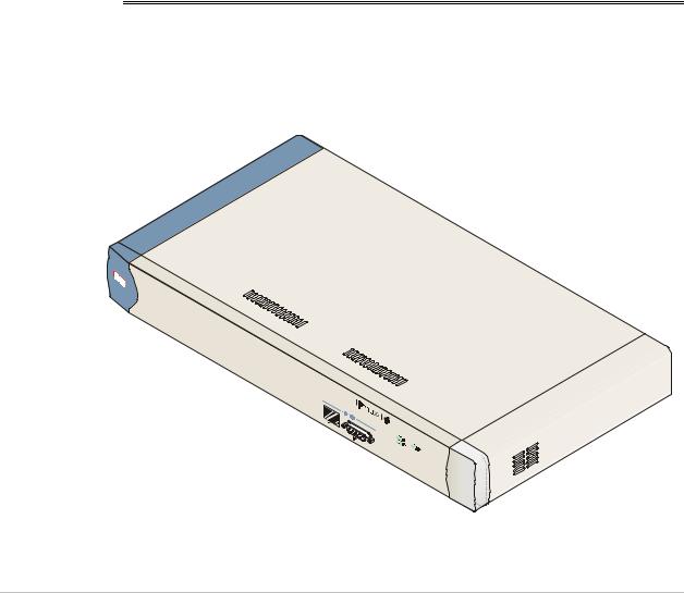
Figure 1-3. IPmux-16 3-D View
Physical Description |
1-5 |
Chapter 1 Introduction |
IPmux-16 Installation and Operation Manual |
|
|
Front Panel
The control port and indicator LEDs are located on the front panel of IPmux-16. For further details see Chapter 2.
Rear Panel
Fuses, power supplies, the dry contact connector, and interface connectors are located on the rear panel of IPmux-16. For further details see Chapter 2.
1.3 Functional Description
IPmux-16 modules support E1 or T1 TDM interfaces. The E1 and T1 modules have either four or eight ports. Each bundle (group of timeslots) can be transmitted to a predefined destination bundle (see the following figure). IPmux-16 supports ICMP (ping), and generates ARP in case of unknown next hop MAC addresses, answers ARP requests, and supports 802.3 Ethernet format.
Configuration and management are provided via the IPmux-16 local terminal, Telnet application or SNMP such as RADview, RAD’s Network Management System.
E1/T1 Port 1 |
IP over |
|
|
Ethernet |
IPmux-16 |
||
E1/T1 Port 2 |
|||
|
|
||
|
IPmux-16 |
|
|
|
|
IPmux-16 |
Figure 1-4. IPmux-16 Point-to-Point Application
Sub E1/T1
IPmux-4
IPmux-1
E1/T1 Line 1 |
|
E1/T1 Line 2 |
IP over |
|
Ethernet |
E1/T1 Line 16 |
IPmux-16 |
IPmux-1
IPmux-16
Sub E1/T1
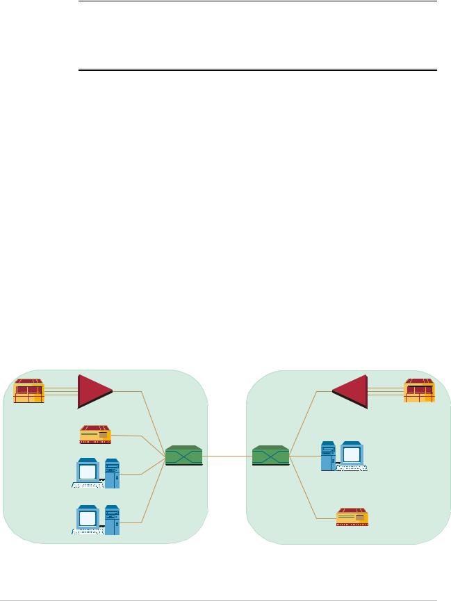
Figure 1-5. Grooming of Timeslots from Remote Sites into a Single E1/T1 Port at Central Site
E1/T1 Port 2
E1/T1 Port 1
Sub E1/T1
Sub E1/T1
1-6 Functional Description

IPmux-16 Installation and Operation Manual |
Chapter 1 Introduction |
|
|
Bundles composed of several timeslots (E1: 1-31, T1: 1-24) can be defined. Each bundle can be connected to a different destination bundle anywhere on the network.
Up to 496 sub-E1 or 384 sub-T1 remote bundles can be attached to one central IPmux-16. Multibundling enables concentrating many remote sites with few timeslots to the same TDM channel at the central site. A mesh topology application, in which the bundles at each site are defined to connect to several sites, is also supported.
Operation Modes
IPmux-16 operation modes are:
•Unframed
•Fractional
•Fractional with CAS
Unframed
In the transparent mode, the incoming bit stream from each port (regardless of framing) is converted into IP over Ethernet frames. This option provides clear channel end-to-end service.
Fractional
In the fractional mode, the incoming bit stream is regarded as a sequence of nx64 Kbps channel groups (according to framing). Each predefined group of channels is converted into a structure block. The structure block is packetized into IP frames and transmitted.
This mode allows transmission of several selected time slots and not the whole E1/T1 as in transparent mode.
Fractional with CAS
In the fractional-with-CAS mode, the structure block (as described under Fractional Operation Modes, above) also includes Channel Associated Signaling (CAS).
Testing
Diagnostic capabilities include E1/T1 local and remote loopback tests for rapid location of faults. Any of the E1/T1 ports can be looped locally toward the line, or toward the remote end (see Chapter 4 for more information).
Timing Modes
The E1/T1 Transmit (TX) clock can operate in several timing modes to provide maximum flexibility for connecting the IPmux-16 E1/T1 interface.
The available timing modes are:
•Loopback: The E1 or T1 Transmit clock is derived from the E1/T1 Receive clock.
Functional Description |
1-7 |

Chapter 1 Introduction |
IPmux-16 Installation and Operation Manual |
|
|
•Adaptive: In this mode, the E1 or T1 Tx clock is regenerated using the Adaptive method. In this method, the fill level of the buffer receiving packets is monitored. If the buffer begins to overfill, the regenerated clock frequency increases to avoid overflow. If the buffer begins to empty, the clock decreases to avoid underflow.
•Internal Clock: In this mode, the Transmit (Tx) clock is received from an internal oscillator. This mode is useful for testing and diagnostic purposes.
Each of the clocks must be configured correctly on both the Receive and Transmit ends to ensure proper operation and prevent pattern slips.
The following paragraphs describe typical timing schemes and their correct timing mode settings in order to achieve end-to-end synchronization.
External Network Timing
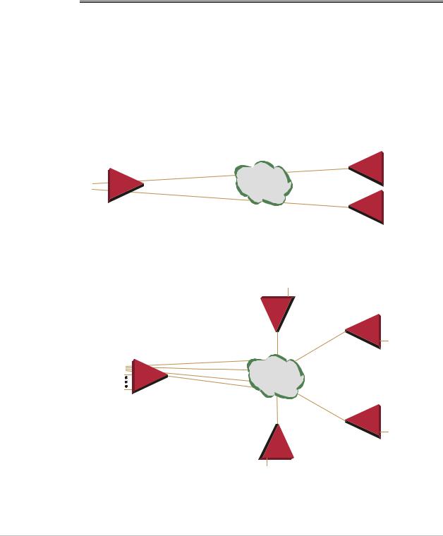
When an external network is used to synchronize the E1/T1 devices, all the IPmux-16 units should be configured to work in loopback mode (see the following illustration). This topology enables any-to-any connectivity; as in the following illustration, all three IPmux-16s have direct E1/T1 connectivity. In this timing configuration both mesh and star bundle connection topologies are supported.
Clock from External Distribution Network
|
|
|
|
|
E1/T1 |
|
E1/T1 |
|
|
|
|
E1/T1 |
|
|
|
IP over |
IPmux-16 |
LBT Mode |
E1/T1 Device |
|
E1/T1 |
|
|
Ethernet |
|
|
|
IPmux-16 |
|
|
|
|||
E1/T1 Device |
|
E1/T1 |
|
|||
|
|
|
|
|
||
|
|
|
|
|
|
|
LBT Mode |
|
|
|
|
E1/T1 |
|
|
|
|
|
IPmux-16 |
E1/T1 Device |
|
|
|
|
|
LBT Mode |
||
Figure 1-6. IPmux-16 in Loopback Timing Mode
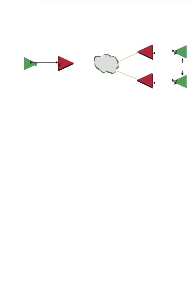
Single Source Clock Network
When a common clock is not available on all the ends of the network:
•E1/T1 Device Configuration:
One of the E1/T1 devices connected to the IPmux-16 should work as the master clock while the others work in loopback timing.
•IPmux-16 Configuration:
The IPmux-16 E1/T1 ports connected to the master clock E1/T1 device work in loopback timing, while the far-end IPmux-16s work in Adaptive mode.
1-8 Functional Description
IPmux-16 Installation and Operation Manual |
Chapter 1 Introduction |
|
|
Note
Master Clock
Source Device
When there are several bundles from different sources at the same E1/T1 port, the bundle that will be used for adaptive clock regeneration for the port is the first bundle of every port. For example (E1): Bundle number 1 for port 1, bundle number 32 for port 2, bundle number 63 for port 3, bundle number 94 for port 4, etc.
In this mode the regenerated clock is subject to network Packet Delay Variation and may not comply with jitter and wander specifications.
|
|
|
|
Adaptive Mode |
|
|
||
|
|
|
|
|
|
E1/T1 |
|
|
Loopback Timing Mode |
|
|
|
E1/T1 |
|
|
||
|
|
|
|
|
|
|
|
|
E1/T1 |
|
|
IP over |
IPmux-16 |
|
|
||
E1/T1 |
Ethernet |
|
|
|
Remote Loopback |
|||
|
Adaptive |
|
Mode |
Timing Devices |
||||
|
IPmux-16 |
|
|
|||||
|
|
|
||||||
|
|
|
|
|
|
E1/T1 |
|
|
|
|
|
|
|
|
E1/T1 |
|
|
|
|
|
|
IPmux-16 |
|
|
||
Figure 1-7. IPmux-16 in Adaptive Timing Mode
Frame Format
The Ethernet frame sent by the IPmux-16 is a UDP datagram which transfers E1/T1 payload bytes over IP over Ethernet (UDP payload + UDP header + IP header + Ethernet header).
The UDP payload size is equal to TDM bytes per frame (TDM bytes/frame configuration).
The illustration below specifies the structure of the different headers, special fields, and the payload in the Ethernet packet.
|
|
|
|
|
MAC |
IP |
UDP |
Payload |
|
|
|
|
|
|
|
|
|
|
|
Figure 1-8. TDMoIP Frame Structure
Functional Description |
1-9 |

Chapter 1 Introduction |
IPmux-16 Installation and Operation Manual |
|
|
Table 1-1. Ethernet Frame Structure
MAC
Layer
LLC
Layer
IP Layer
UDP
Layer
Data
Layer
MAC
Layer
Field length (bytes) |
Field |
|
|
7 |
Preamble |
|
|
1 |
SFD |
|
|
6 |
Destination MAC Address |
|
|
6 |
Source MAC Address |
|
|
2 |
Type |
|
|
1 |
Vers/HLEN |
|
|
1 |
Service Type |
|
|
2 |
Total Length |
|
|
2 |
Identification |
|
|
1 |
Flags/Fragment Offset (most) |
|
|
1 |
Fragment Offset (least) |
|
|
1 |
Time to Live |
|
|
1 |
Protocol |
|
|
2 |
Header Checksum |
|
|
4 |
Source IP Address |
|
|
4 |
Destination IP Address |
|
|
2 |
UDP Source Port |
|
|
2 |
UDP Destination Port |
|
|
2 |
UDP Message Length |
|
|
2 |
UDP Checksum |
|
|
... |
Payload |
|
|
|
|
4 |
CRC |
|
|
IEEE 802.1p&q VLAN Tagging (additional 4 bytes if enabled)
Note: The UDP source port field is used to transfer a destination bundle number.
1-10 Functional Description

IPmux-16 Installation and Operation Manual |
Chapter 1 Introduction |
|
|
VLAN Support
VLAN, according to IEEE 802.1p&q, adds four bytes to the MAC layer of the Ethernet frame. The contents of these bytes, MAC layer priority and VLAN ID, can be set by the user. In this mode, only VLAN format frames are sent and received by IPmux-16. The following figure describes the VLAN tag format.
81 |
00 |
|
|
802.1D Tag Protocol Type
(802.1QTagType)
user_priority |
0 |
|
|
|
VID |
|
|
|
CFI = |
|
|
|
|
8 |
6 |
5 |
4 |
1 |
8 |
1 |
|
Priority |
|
|
|
|
VLAN ID |
Figure 1-9. VLAN Tag Format
UDP Support
Table 1-2. UDP Source Port as Destination Voice Port
Field Length (Bits) |
Field Description |
Value |
|
|
|
2 bytes |
UDP Source Port* |
2 – 497d |
|
|
|
2 bytes |
UDP Destination Port |
2142d |
|
|
|
* The MSB of this field can be either 1 or 0 for inband end-to-end proprietary signaling.
Note The UDP Source Port field is used for destination voice bundle indication. For example, if the destination is:
Bundle 1 – 02, Bundle 2 – 03, Bundle 3 – 04, Bundle 4 – 05, etc.
For more information about VLAN tagging, see IEEE Std 802.1 p&q.
Packet Delay Variation
Packets are transmitted at set intervals. Packet Delay Variation is the maximum deviation from the nominal time the packets are expected to arrive at the far end device. IPmux-16 has a buffer that compensates for the deviation from the expected packet arrival time to prevent IPmux-16 buffers from emptying out.
Packet Delay Variation is an important network parameter. Large PDV (exceeding the jitter buffer configuration) will cause receive buffer underflows and errors at the E1/T1 level (see Figure 1-10).
To compensate for large PDV, the PDVT (jitter) buffer should be configured to a higher value.
Functional Description |
1-11 |

Chapter 1 Introduction |
IPmux-16 Installation and Operation Manual |
|
|
Packets Leaving IPmux-16  t
t
Packets Arriving  t
t
PDV
Figure 1-10. Packet Delay Variation
PDVT (Jitter) Buffer
IPmux-16 is equipped with a Packet DVT (Delay Variation Tolerance) buffer. The PDVT buffer or jitter buffer is filled by the incoming IP packets and emptied out to fill the E1/T1 stream. The buffer begins to empty out only after it is half full in order to compensate for packet starvation from the Ethernet side. The time it takes for half of the buffer to empty out is the maximum DVT time. Delay Variation Tolerance is configurable. The PDVT (jitter) buffer is designed to compensate for packet delay variation caused by the network.
It supports a delay variation of up to E1: 32 ms, T1: 24 ms.
To configure jitter buffer depth:
Estimated or Measured PDV introduced by the network + intrinsic PDV (if it exists) introduced by the module as a result of configuring the
TDM bytes / frame > 48 (see explanation of calculating intrinsic PDV, below).
Intrinsic PDV
If TDM bytes/frame is greater than 48, there is an intrinsic delay variation (intrinsic PDV). The intrinsic PDV introduced by the module is a function of n>1 in
TDM bytes/frame configuration as follows:
I.PDV (ms) = ((n – 1) x 1000) / (frames per second × n)
Where n = configured TDMbytes/frame (n=1 – 8). 48
PDVT Buffer Effect on Delay
The PDVT buffer is on the TDM path. This means that it adds to the total end-to-end delay (see delay calculation, below).
1-12 Functional Description
IPmux-16 Installation and Operation Manual |
Chapter 1 Introduction |
|
|
Ethernet Throughput
Configuring the TDM bytes per frame (TDM bytes/frame) parameter, per bundle configuration, can reduce Ethernet throughput (bandwidth or traffic travelling through the Ethernet). This parameter controls the number of TDM bytes encapsulated in one frame. The TDM bytes/frame parameter can be configured to nX48 bytes where n is an integer between 1 and 8. Configuring TDM bytes/frame to a higher value reduces the IP/Ethernet overhead segment of the total packet and thus can significantly reduce the total Ethernet throughput.
On the other hand, packetization delay and intrinsic packet delay variation (PDVT) are increased and this contributes to a higher end-to-end delay. This effect can be small and negligible when a full E1 (or many timeslots) are transferred but can be very significant when few E1/T1 timeslots are transferred. In this case, the packetization delay and the intrinsic PDV when configuring a large value of TDM bytes / frame can be very large and may exceed the maximum PDVT (jitter) buffer on the receiving end. The tables below show the throughput as a function of the TDM bytes/frame configuration for a full E1 and a full T1.
Table 1-3. Ethernet Throughput – Unframed E1
TDM |
Frame |
Overhead |
Overhead |
Packets |
Throughput |
bytes/frame |
Length |
(bytes) |
(%) |
(per |
(Mbps) |
|
(bytes) |
|
|
second) |
|
|
|
|
|
|
|
48 |
94 |
46 |
96 |
5447 |
4.1 |
|
|
|
|
|
|
96 |
142 |
46 |
48 |
2724 |
3.1 |
|
|
|
|
|
|
144 |
190 |
46 |
32 |
1816 |
2.76 |
|
|
|
|
|
|
192 |
238 |
46 |
24 |
1362 |
2.6 |
|
|
|
|
|
|
240 |
286 |
46 |
19 |
1089 |
2.5 |
|
|
|
|
|
|
288 |
334 |
46 |
16 |
908 |
2.43 |
|
|
|
|
|
|
336 |
382 |
46 |
14 |
778 |
2.38 |
|
|
|
|
|
|
384 |
430 |
46 |
12 |
681 |
2.34 |
|
|
|
|
|
|
Functional Description |
1-13 |

Chapter 1 Introduction IPmux-16 Installation and Operation Manual
|
Table 1-4. |
Ethernet Throughput – Unframed T1 |
|
||
|
|
|
|
|
|
TDM |
Frame |
Over head |
Over head |
Packets |
Throughput |
bytes/frame |
length |
(bytes) |
(%) |
(per |
(Mbps) |
|
(bytes) |
|
|
second) |
|
|
|
|
|
|
|
48 |
94 |
46 |
96 |
4107 |
3.08 |
|
|
|
|
|
|
96 |
142 |
46 |
48 |
2054 |
2.32 |
|
|
|
|
|
|
144 |
190 |
46 |
32 |
1369 |
2.07 |
|
|
|
|
|
|
192 |
238 |
46 |
24 |
1027 |
1.95 |
|
|
|
|
|
|
240 |
286 |
46 |
19 |
821 |
1.87 |
|
|
|
|
|
|
288 |
334 |
46 |
16 |
685 |
1.82 |
|
|
|
|
|
|
336 |
382 |
46 |
14 |
587 |
1.78 |
|
|
|
|
|
|
384 |
430 |
46 |
12 |
513 |
1.76 |
|
|
|
|
|
|
To calculate Ethernet throughput and intrinsic PDV as a function of TDM bytes/frame:
Ethernet load (bps) = [(frame overhead (bytes) + TDM bytes/frame) × 8] × frames/second Frame overhead = Ethernet overhead + IP overhead = 46 bytes
Frame/second =
unframed: 5447/n for a full E1 4107/n for a full T1
framed: |
8000Xk / (46.875 x n) |
||
|
Where k = number of assigned timeslots |
||
|
Where n = |
TDM bytes/frame |
|
|
|
||
|
48 |
|
|
Round Trip Delay
The voice path round-trip delay, which is a function of all connections and network parameters, is calculated for E1/T1 as follows:
RTDelay( s) = 2 x ( 48×n x 125 (µs) + PDVT buffer (µs) +500 (µs))+ Network round trip delay
NTS
Where n = TDM bytes/frame 48
Where NTS = number of timeslots assigned in unframed E1 interface = 32
T1 interface = 24
1-14 Functional Description

IPmux-16 Installation and Operation Manual |
Chapter 1 Introduction |
|
|
End-to-End Alarm Generation
An end-to-end alarm generation mechanism exists in the IPmux-16 to facilitate the following alarms:
Unframed |
AIS will be transmitted toward the near-end PBX in event of: |
|
• Far-end LOS, AIS |
|
• PDVT underflow/overflow. |
Framed |
Timeslot / CAS configurable alarm pattern will be transmitted |
|
toward the near-end PBX in event of: |
|
• Far-end LOS, LOF, AIS |
|
• PDVT underflow/overflow. |
Throughput Limitations and CAC
Ethernet port throughput of IPmux-16 is limited to a number (pps) that is smaller than the number (pps) that should be transmitted when all 16 E1/T1 channels are active with 48 bytes per frame. To prevent configurations that will exceed this limit, a CAC mechanism exists and will prevent adding connections as soon as the limit is exceeded. The mechanism also monitors and displays current system performance optimization (percentage of budget in use).
Table 1-5. System Usage for TDM Bytes per Frame
TDM Bytes/Frame |
System Resources Consumption per Timeslot |
|
|
48 |
0.39% |
|
|
96 |
0.2145% |
|
|
144 |
0.1521% |
|
|
192 |
0.1209% |
|
|
240 |
0.1014% |
|
|
288 |
0.0897% |
|
|
336 |
0.0858% |
|
|
384 |
0.078% |
|
|
Functional Description |
1-15 |

Chapter 1 Introduction |
IPmux-16 Installation and Operation Manual |
|
|
1.4 Technical Specifications
E1 Modules
E1 Port |
Ports |
|
Compliance |
|
Connector |
|
Data Rate |
|
Line Code |
|
Line Impedance |
|
Signal Levels |
|
Jitter Performance |
|
External Adapter |
|
Cable |
E1 |
Compliance |
Framing |
Framing |
|
Signaling |
T1 Modules
Up to 16
ITU-T Rec. G.703, G.706, G.732, G.823
Balanced: RJ-45 8 pin
Unbalanced: TBNC 75Ω (an external adapter cable from TBNC to BNC is required)
2.048 Mbps HDB3
Balanced: 120Ω; Unbalanced: 75Ω
Receive: 0 to –27 dB with LTU
0 to –10 dB without LTU Transmit Balanced: ±3V ±10% Transmit Unbalanced: ±2.37V ±10%
ITU-T G.823 standard
TBNC to BNC required for unbalanced interfaces
G.704, G.706
Passthrough, CRC4 MF, CAS MF
CAS, CCS (transparent)
T1 Port |
Ports |
|
Compliance |
|
Connector |
|
Data Rate |
|
Line Code |
|
Line Impedance |
|
Signal Levels |
Jitter Performance
Up to 16
ANSI T1.403, ITU-T Rec. G.703 RJ-45, 8 pin
1.544 Mbps B8ZS, B7ZS, AMI Balanced: 100Ω
Receive: 0 to –27 dB
Transmit: 0 dB, –7.5 dB, –15 dB, –22.5 with CSU
±2.7V ± 10%, adjustable, measured in range 0 to 655 feet without CSU
AT&T TR-62411, G.824 standards
1-16 Technical Specifications

IPmux-16 Installation and Operation Manual |
|
|
Chapter 1 Introduction |
||
|
|
|
|
|
|
T1 |
Compliance |
ANSI T1.403 |
|
|
|
Framing |
Framing |
Passthrough, SF, ESF |
|
||
|
Signaling |
CAS (bit robbing), CCS (transparent) |
|||
Local |
|
RS-232 over RJ-45 (adapter cable to DB-15 supplied) |
|||
Terminal |
Mode |
DTE |
|
|
|
and |
Baud Rate |
9.6, 19.2, 38.4, 57.6, 115.2 kbps |
|||
Control |
|||||
|
|
|
|
||
Interface |
Connector |
DB-9 |
|
|
|
Dry |
Connector |
DB-9 |
|
|
|
Contact |
Contacts |
30V 2A |
|
|
|
Alarm |
|
|
|||
|
|
|
|
||
Ethernet |
Compliance |
IEEE 802.3, 802.3u, Ethernet, 802.1 p&q |
|||
Modules |
Connector |
RJ-45, 8 pin |
|
|
|
|
Ports |
1 |
|
|
|
|
Data Rate |
10 Mbps or 100 Mbps, full or half duplex |
|||
|
Range |
Up to 100m over UTP Category 5 cables |
|||
General |
System Indicators |
General: |
|
|
|
|
|
PS1 |
Green |
ON when main power supply is |
|
|
|
|
|
OK |
|
|
|
|
|
OFF when malfunction is |
|
|
|
|
|
detected, power does not exist or |
|
|
|
|
|
power is off. |
|
|
|
PS2 |
Green |
ON when secondary power |
|
|
|
|
|
supply is OK |
|
|
|
|
|
OFF when secondary power |
|
|
|
|
|
supply does not exist (no power |
|
|
|
|
|
supply redundancy) or when |
|
|
|
|
|
power is off |
|
|
|
RDY |
Green |
ON when self-test is successfully |
|
|
|
|
|
completed |
|
|
|
|
|
OFF during self-test |
|
|
|
|
|
BLINKS when self-test fails |
|
|
|
ALM |
Red: |
ON when a Minor alarm is |
|
|
|
|
|
detected |
|
OFF when no alarms are detected
Technical Specifications |
1-17 |

Chapter 1 Introduction |
IPmux-16 Installation and Operation Manual |
|
|
Power
Physical
Environment
Humidity
Ethernet Port:
LINK |
OFF when line is not active |
|
ON when line is OK |
ACT |
OFF when no activity |
|
ON when a frame is being transmitted or |
|
received on the line |
FDX |
OFF when half duplex |
|
ON when full duplex |
100M |
OFF when 10 MHz |
|
ON when 100 MHz |
E1/T1 Port: |
|
SYNC |
ON when the port is synchronized (no alarm) |
|
OFF when signal loss, LOF or AIS is detected |
|
(local alarm) |
|
BLINKS when RDI is detected (remote alarm) |
Note: All LEDs are green and ON after power-up.
1 or 2 power supplies
40W, 100 to 240 VAC, 50/60 Hz –36 to –72 VDC (–48 VDC nominal)
Height 6.6 cm / 2.55 in (1.5U) Width 43.2 cm / 19 in
Depth 35 cm / 13.78 in Weight 4.0 kg / 8.8 lb
Temperature: 0 to 45°C / 32 to 110°F Up to 90%, non-condensing
1-18 Technical Specifications

Chapter 2
Installation
2.1 Introduction
IPmux-16 is delivered completely assembled for bench-top installation. The only mechanical installation procedure that may be necessary is optional installation in a 19-inch rack.
After installing the unit, configure the IPmux-16 using an ASCII terminal connected to the IPmux-16 control port. The IPmux-16 configuration procedures are described in Chapter 3 of this manual.
If problems are encountered, refer to Chapter 4 for test and diagnostics instructions.
No internal settings, adjustment, maintenance and repairs may be performed by either the operator or the user; such activities may be performed only by
skilled service personnel who are aware of the hazards involved.
Warning Always observe standard safety precautions during installation, operation, and maintenance of this product.
2.2 Site Requirements and Prerequisites
AC-powered IPmux-16 units should be installed within 1.5m (5 feet) of an easily-accessible grounded AC outlet capable of furnishing the required supply voltage, in the range of 100 to 240 VAC, 16A maximum.
DC-powered IPmux-16 units require a –48 VDC power source (positive pole grounded).
Caution The DC power source must be isolated from the mains supply by double or reinforced insulation.
Allow at least 90 cm (36 in) of frontal clearance for operator access. Allow at least 10 cm (4 in) clearance at the rear of the unit for cable connections. Make sure that the ventilation holes are not blocked.
Site Requirements and Prerequisites |
2-1 |

Chapter 2 Installation IPmux-16 Installation and Operation Manual
The ambient operating temperature of IPmux-16 is 0o to 50o C
(32o F to 122o F), at a relative humidity of up to 90%, non-condensing.
2.3 Package Contents
The IPmux-16 package contains the following items:
•IPmux-16 unit
•Power cord
•CBL-DB9/DB9/NULL cross-cable that connects the IPmux-16 control port and an ASCII terminal (DTE) for local management.
•RM-11 kit containing hardware for mounting IPmux-16 in a 19-inch rack (optionally supplied).
Power Cable
IPmux-16 comes equipped with the power cord connected to PS1. If the unit is equipped with a redundant power supply, IPmux-16 is equipped with an additional power cord.
2.4 Equipment Needed
•Hand Tools and Kits
IPmux-16 needs no special tools for installation. A screwdriver is necessary when mounting IPmux-16 in a 19-inch rack.
•Control Cable
IPmux-16 is provided with one null cable.
The null cable (CBL-DB9/DB9/NULL) is used to connect IPmux-16 (DTE) to a terminal (DTE). Terminals are usually equipped with a male connector DB-9 or DB-25; therefore the null cable should have a female connector.
A straight cable can be defined to connect IPmux-16 (DTE) to a modem (DCE).
2-2 Equipment Needed
IPmux-16 Installation and Operation Manual Chapter 2 Installation
Table 2-1. Null Cable Pinout Connections
DB-9 Female |
Signal |
Name |
Pin No. |
|
|
|
|
|
1 |
DCD |
Data Carrier Detect |
|
|
|
2 |
RXD |
Receive data |
|
|
|
3 |
TXD |
Transmit data |
|
|
|
4 |
DTR |
Data Terminal Ready |
|
|
|
5 |
GND |
Ground |
|
|
|
6 |
DSR |
Data Set Ready |
|
|
|
7 |
RTS |
Request To Send |
|
|
|
8 |
CTS |
Clear To Send |
|
|
|
9 |
RI |
Ring Indicator |
|
|
|
On both DB9 connectors, DCD (pin 1), DTR (pin 4) and DSR (6) are connected together.
RTS (pin 7) is shorted together with CTS (pin 8). Refer to Figure 2-1.
CBL-DB-9/DB9/NULL |
|
DB-9 (Female) |
DB-9 (Female) |
1 |
1 |
2 |
2 |
3 |
3 |
4 |
4 |
5 |
5 |
6 |
6 |
7 |
7 |
8 |
8 |
9 |
9 |
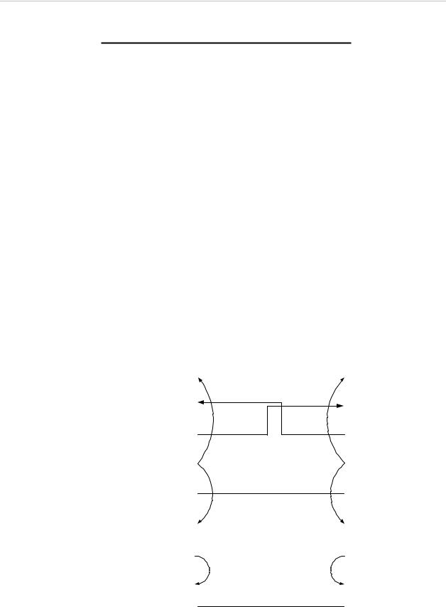
Figure 2-1. Null Cable (CBL-DB-9/DB-9/NULL) Pin Shorts
Equipment Needed |
2-3 |
Chapter 2 Installation |
IPmux-16 Installation and Operation Manual |
|
|
2.5 Installation and Setup
Setting Jumpers
IPmux-16 internal jumpers and switches do not need to be configured by the user and therefore removing the product cover is not required.
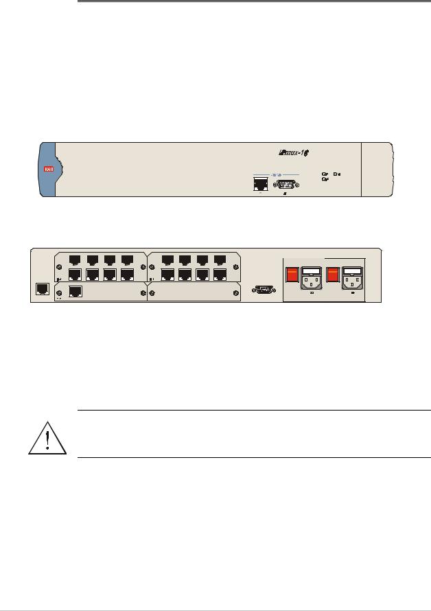
Connecting Interfaces and Cables
Figure 2-2 and Figure 2-3 illustrate the rear and front panel options available for IPmux-16.
Figure 2-2. IPmux-16 Front Panel
|
|
|
|
|
|
|
|
|
|
|
|
|
|
|
PS1 |
POWER |
|
|
|
PS2 |
|
|
|
|
|
|
|
|
|
|
|
|
|
|
|
|
|
POWER |
|||
|
|
|
|
|
|
|
|
|
|
|
|
|
|
|
|
|
|
|
|
|
I |
I |
O |
O |
|
|
|
|
|
|
|
|
|
|
|
|
|
|
|
|
~100-240VAC |
|
3A T 125V |
~100-240VAC 3A T 125V |
||||
EXT. CLK |
ALARMS |
Figure 2-3. IPmux-16 Rear Panel
Grounding
Interrupting the protective grounding conductor (inside or outside the instrument) or disconnecting the protective earth terminal can make this instrument dangerous. Intentional interruption is prohibited.
Before switching ON this instrument and before connecting any other cable, the protective earth terminals of this instrument must be connected to the
protective ground conductor of the power cord.
Warning
Fuses
Make sure that only fuses with the required rated current and specified type, 2 A T 250V as marked on the IPmux-16 rear panel, are used for replacement.
Whenever it is likely that the protection offered by fuses has been impaired, the instrument must be made inoperative and be secured to prevent any operation.
2-4 Installation and Setup
Loading...