

Page 1

ASMi-450
High-Speed HDSL Modem
Installation and Operation Manual
Notice
This manual contains information that is proprietary to RAD Data Communications. No part of this
publication may be reproduced in any form whatsoever without prior written approval by RAD Data
Communications.
No representation or warranties for fitness for any purpose other th an wh at is specifically mentioned in this
manual is made either by RAD Data Communications or its agents.
For further information contact RAD Data Communications at the address below or contact your local
distributor.
RAD data communications
Headquarters
12 Hanechoshet Street
Tel Aviv 69710 Israel
Tel: 972-3-6458181
Fax: 972-3-6498250
E-mail: rad@radmail.rad.co.il
© 1997 RAD Data Communications Ltd. Publication No. 634-200-11/97
RAD data communications
US East
900 Corporate Drive
Mahwah, NJ 07430 USA
Tel: (201) 529-1100
Fax: (201) 529-5777
E-mail: market@radusa.com
RAD data communications
US West
7711 Center Avenue #350
Huntington Beach, CA 92647 USA
Tel: (714) 897-2448
Fax: (714) 891-1764
Page 2

Warranty
This RAD product is warranted against defects in material and workmanship for a period of one year from
date of shipment. During the warranty period, RAD will, at its option, either repair or replace products
which prove to be defective. For warranty service or repair, this product must be returned to a service
facility designated by RAD. Buyer shall prepay shipping charges to RAD and RAD shall pay shipping
charges to return the product to Buyer. However, Buyer shall pay all shipping charges, duties and taxes for
products returned to RAD from another country.
Limitation of Warranty
The foregoing warranty shall not apply to defects resulting from improper or inadequate maintenance by
Buyer, Buyer-supplied firmware or interfacing, unauthorized modification or misuse, operation outside of
the environmental specifications for the product, or improper site preparation or maintenance.
Exclusive Remedies
The remedies provided herein are the Buyer’s sole and exclusive remedies. RAD shall not be liable for any
direct, indirect special, incidental, or consequential damages, whether based on contract, tort, or any legal
theory.
Page 3
Safety Warnings
The exclamation point within a triangle is intended to warn the operator or service
personnel of operation and maintenance factors relating to the product and its operating
environment which could pose a safety hazard.
Always observe standard safety precautions during installation, operation and maintenance of this product.
Only qualified and authorized service personnel should carry out adjustment, maintenance or repairs to this
instrument. No adjustment, maintenance or repairs should be performed by either the operator or the user.
Telecommunication Safety
The safety status of each of the ports on the ASMi-450 is declared according to EN 41003 and is detailed
in the table below:
Safety Status Ports
SELV RS-530, X.21, V.35, V.24, V.36
TNV operating within the limits of SELV HDSL
SELV = Safety Extra-Low Voltage
TNV = Telecommunications Network Voltage
Page 4

Regulatory Information
FCC-15 User Information
This equipment has been tested and found to comply with the limits of the Class A digital device, pursuant
to Part 15 of the FCC rules. These limits are designed to provide reasonable protection against harmful
interference when the equipment is operated in a commercial environment. This equipment generates, uses
and can radiate radio frequency energy and, if not installed and used in accordance with the instruction
manual, may cause harmful interference to the radio communications. Operation of this equipment in a
residential area is likely to cause harmful interference in which case the user will be required to correct the
interference at his own expense.
Warning per EN 55022
This is a Class A product. In a domestic environment, this product may cause radio interference, in which
case the user may be required to take adequate measures.
Page 5

Declaration of Conformity
Manufacturer’s Name:
Manufacturer’s Address:
declares that the product:
Product Name: ASMi-450
Conforms to the following standard(s) or other normative document(s):
EMC:
Safety:
Supplementary Information:
The product herewith complies with the requirements of the EMC Directive 89/336/EEC and the
Low Voltage Directive 73/23/EEC. The product was tested in a typical configuration.
EN 55022 (1994) Limits and methods of measurement of radio disturbance
EN 50082-1 (1992) Electromagnetic compatibility - Generic immunity
EN 60950 (1992/93) Safety of information technology equipment, including
RAD Data Communications Ltd.
12 Hanechoshet St.
Tel Aviv 69710
Israel
characteristics of information technology equipment.
standards for residential, commercial and light industry.
electrical business equipment.
Tel Aviv, January 23rd, 1997
European Contact:
RAD Data Communications GmbH, Lyoner Strasse 14, 60528 Frankfurt am Main, Germany
Haim Karshen
VP Quality
Page 6

Page 7

Chapter 1 Introduction
1.1 Functional Description....................................................................................................................... 1-1
Purpose and Main Features............................................................................................................... 1-1
Serial Data Port Characteristics ........................................................................................................1-2
Ethernet Interface Characteristics.....................................................................................................1-2
HDSL Subsystem Characteristics.....................................................................................................1-3
System Timing..................................................................................................................................1-4
Control of ASMi-450 Operation....................................................................................................... 1-5
1.2 Operating Environment...................................................................................................................... 1-8
Transmission Media..........................................................................................................................1-8
HDSL Line Signal ............................................................................................................................1-8
HDSL Signal Structure..................................................................................................................... 1-9
HDSL-Related System Functions.....................................................................................................1-9
1.3 Technical Specifications ..................................................................................................................1-10
Chapter 2 Installation
2.1 General...............................................................................................................................................2-1
2.2 Unpacking.......................................................................................................................................... 2-2
2.3 Site Requirements .............................................................................................................................. 2-2
Power................................................................................................................................................2-2
User's Port Connections.................................................................................................................... 2-2
HDSL Line Connections................................................................................................................... 2-2
Front and Rear Panel Clearance........................................................................................................2-2
Ambient Requirements .....................................................................................................................2-2
2.4 ASMi-450 Configuration Information............................................................................................... 2-3
General.............................................................................................................................................. 2-3
Opening ASMi-450 Case.................................................................................................................. 2-3
Jumper and Switch Location and Functions.....................................................................................2-4
Internal Settings Procedure...............................................................................................................2-7
Reinstalling ASMi-450 Cover ..........................................................................................................2-7
2.5 Connections................................................................................................................ ........................ 2-8
Connector Location........................................................................................................................... 2-8
Grounding......................................................................................................................................... 2-8
Power Connection............................................................................................................................. 2-9
User's Port Connections.................................................................................................................... 2-9
HDSL Line Connections................................................................................................................. 2-10
Control Port Connection................................................................................................................. 2-10
Contents
Chapter 3 Front-Panel Operating Instructions
3.1 Scope.................................................................................................................................................. 3-1
3.2 Front Panel Controls, Connectors, and Indicators ............................................................................. 3-2
Ethernet Interface Indicators............................................................................................................. 3-3
3.3 Control of ASMi-450 Operation, General ......................................................................................... 3-4
General.............................................................................................................................................. 3-4
General Operating Instructions.........................................................................................................3-4
Display Functions .............................................................................................................................3-4
ASMi-450 Installation and Operation Manual vii
Page 8

Contents
Organization of ASMi-450 Display.................................................................................................. 3-6
Using Front-Panel Push-buttons....................................................................................................... 3-6
3.4 System Configuration Parameters......................................................................................................3-8
3.5 Control Port Configuration Parameters..............................................................................................3-9
3.6 Operating Instructions...................................................................................................................... 3-10
Turn-on........................................................................................................................................... 3-10
Checking Current Operating Configuration....................................................................................3-10
Normal Indications.......................................................................................................................... 3-11
Fault Indications ............................................................................................................................. 3-12
Turn-off...........................................................................................................................................3-12
3.7 Local Configuration Set-Up Procedure............................................................................................3-13
Password Protection........................................................................................................................3-13
General Configuration Procedure...................................................................................................3-13
Specific Configuration Guidelines..................................................................................................3-15
3.8 LCD Configuration Error Messages ................................................................................................3-17
Chapter 4 ASMi-450 Control from the Control Port........................................................................................... 4-1
4.1 General...............................................................................................................................................4-1
4.2 Hardware Requirements.....................................................................................................................4-2
Terminal Characteristics................................................................................................................... 4-2
Communication Requirements.......................................................................................................... 4-2
Handshaking Protocol ....................................................................................................................... 4-2
AUTOBAUD Function..................................................................................................................... 4-4
4.3 Preparation for Use of Supervision Terminal ....................................................................................4-5
ASMi-450 Preparations .................................................................................................................... 4-5
Supervision Terminal........................................................................................................................4-5
Connections ...................................................................................................................................... 4-5
4.4 ASMi-450 Supervision Language......................................................................................................4-6
Command Language Syntax.............................................................................................................4-6
Command Options............................................................................................................................ 4-6
Command Protocol ...........................................................................................................................4-6
Index of Commands.......................................................................................................................... 4-7
4.5 ASMi-450 Command Set Description ............................................................................................... 4-9
4.6 Control Terminal Operating Instructions.........................................................................................4-26
Starting a Session - Single ASMi-450 ............................................................................................4-26
Starting a Session - Multiple ASMi-450......................................................................................... 4-27
Control Session............................................................................................................................... 4-27
Ending a Control Session................................................................................................................4-28
4.7 Configuration Error Messages.........................................................................................................4-29
Chapter 5 Diagnostics
5.1 General...............................................................................................................................................5-1
5.2 Status Indications and Messages........................................................................................................ 5-1
Indicators .......................................................................................................................................... 5-1
Display..............................................................................................................................................5-1
5.3 Test Functions....................................................................................................................................5-6
Test Functions................................................................................................................................... 5-6
TEST OPTIONS Operating Instructions .......................................................................................... 5-7
viii ASMi-450
Installation and Operation Manual
Page 9

Activating the Test Functions from a Control Terminal................................................................... 5-8
5.4 Power-Up Self-Test ...........................................................................................................................5-8
5.5 Troubleshooting Instructions ............................................................................................................. 5-9
Appendix A Connector Wiring
A.1 RS-530 DCE Connector and Adapter Cables .................................................................................. A-1
A.2 V.35 DCE Connector....................................................................................................................... A-3
A.3 X.21 DCE Connector....................................................................................................................... A-4
A.4 HDSL Line Connector ..................................................................................................................... A-5
A.5 RS-232 (V.24) Control Port Connector ........................................................................................... A-5
A.6 Ethernet Interface Connector ........................................................................................................... A-6
Appendix B SNMP Management
B.1 Scope................................................................................................................................................ B-1
B.2 SNMP Environment......................................................................................................................... B-2
General............................................................................................................................................. B-2
SNMP Principles.............................................................................................................................. B-2
SNMP Operations.................................................................................................................................. B-2
The Management Information Base....................................................................................................... B-3
MIB Structure........................................................................................................................................ B-3
MIBs Supported by the ASMi-450 SNMP Agent ................................................................................. B-3
Management Domains Under SNMP .............................................................................................. B-4
SNMP Communities.............................................................................................................................. B-4
Access Restriction Using SNMP Communities..................................................................................... B-4
ASMi-450 Communities........................................................................................................................ B-5
Contents
B.3 IP Environment................................................................................................................................. B-6
General............................................................................................................................................. B-6
IP Environment................................................................................................................................ B-6
IP Address Structure.............................................................................................................................. B-6
B.4 SNMP Traps..................................................................................................................................... B-8
Appendix C Installation in 19" Racks
C.1 General............................................................................................................................................. C-1
C.2 Installation of Single Unit ................................................................................................................ C-2
C.3 Installation of Two Units.................................................................................................................. C-3
General............................................................................................................................................. C-3
Preparations ..................................................................................................................................... C-3
Fastening the Two Units.................................................................................................................. C-4
ASMi-450
Installation and Operation Manual
ix
Page 10

Contents
x ASMi-450
Installation and Operation Manual
Page 11

List of Figures
Figure 1-A. Typical Application for ASMi-450 with Data Interface ........................................................................1-2
Figure 1-B. Typical Application for ASMi-450 with Ethernet Interface................................................................... 1-2
Figure 1-C. Flow of Timing Signals through ASMi-450 System in the External Timing Mode...............................1-4
Figure 1-D. Flow of Timing Signals through ASMi-450 System in the Internal Timing Mode ...............................1-5
Figure 1-E. 2B1Q Encoding Rule.............................................................................................................................. 1-8
Figure 2-1. Identification of Cover Screws................................................................................................................ 2-4
Figure 2-2. ASMi-450 Internal Settings .................................................................................................................... 2-5
Figure 2-3. Typical ASMi-450 Rear Panels............................................................................................................... 2-8
Figure 3-A. ASMi-450 Front Panel...........................................................................................................................3-2
Figure 3-B. ASMi-450 Rear Panel (Ethernet Interface) ............................................................................................ 3-3
Figure 5-A. LOOP LOCAL PORT Loopback...........................................................................................................5-6
Figure 5-B. LOOP REM REM PORT Loopback...................................................................................................... 5-7
Figure C-1. Installation of Single Unit in 19" Rack.................................................................................................. C-2
Figure C-2. Preparation of Two ASMi-450 Units for Installation in 19" Rack........................................................ C-3
Figure C-3. Attachment of Two ASMi-450 Units Before Installation in 19" Rack.................................................. C-4
ASMi-450 Installation and Operation Manual xi
Page 12

List of Figures
xii ASMi-450
Installation and Operation Manual
Page 13

List of Tables
Table 3-A. ASMi-450 Controls, Connectors and Indicators ..................................................................................... 3-2
Table 3-B. Ethernet Interface Indicators....................................................................................................................3-3
Table 3-C. System Parameters...................................................................................................................................3-8
Table 3-D. Control Port Parameters........................................................................................................................... 3-9
Table 4-A. ASMi-450 Command Set Index ..............................................................................................................4-8
Table 4-B. Control Terminal Alarm Messages........................................................................................................ 4-17
Table 4-2. Control Terminal Alarm Messages (Cont’d).......................................................................................... 4-18
Table 4-2. Control Terminal Alarm Messages (Cont’d).......................................................................................... 4-19
Table 4-C. ASMi-450 Default Configuration Used with Control Terminal............................................................ 4-23
Table 5-A. ASMi-450 Alarm Buffer Messages.........................................................................................................5-2
Table 5-1. ASMi-450 Alarm Buffer Messages (Cont’d)........................................................................................... 5-3
Table 5-1. ASMi-450 Alarm Buffer Messages (Cont’d)........................................................................................... 5-4
Table 5-1. ASMi-450 Alarm Buffer Messages (Cont’d)........................................................................................... 5-5
Table 5-B. Troubleshooting Chart............................................................................................................................. 5-9
Table 5-2. Troubleshooting Chart (Cont’d)............................................................................................................. 5-10
Table A-1. RS-530 DCE Connector ......................................................................................................................... A-1
Table A-2. V.36/RS-449/422 DCE Interface Adapter Cable.................................................................................... A-2
Table A-3. V.35 DCE Connector.............................................................................................................................. A-3
Table A-4. DCE Connector, X.21 Interface ....................................................................................... ...................... A-4
Table A-5. LINE Connector, Pin Allocation ............................................................................................................ A-5
Table A-6. Control Port Interface Signals ................................................................................................................ A-5
Table A-7. Ethernet Interface Connector.................................................................................................................. A-6
ASMi-450 Installation and Operation Manual xiii
Page 14

List of Tables
xiv ASMi-450
Installation and Operation Manual
Page 15

Quick-Start Guide
If you are familiar with HDSL transmission equipment, use this guide to prepare
(configure) an ASMi-450 for operation. The configuration activities can be
carried out either before or after the ASMi-450 is installed in its intended
location.
1. Starting the Configuration
Preliminary
Preparations
Starting Procedure
To configure the ASMi-450, you need an ASCII terminal, e.g., a VT-100, etc.,
or a PC running a terminal emulation program. You also need a standard cable
terminated in a 9-pin D-type male connector, for connecting the serial port of
your terminal to the CONTROL DCE connector located on the front panel of the
ASMi-450.
Configure your terminal for eight data bits, no parity, one stop bit, echo off, and
no flow control. You can use 300, 1200, 2400, 4800, or 9600 bps - the
ASMi-450 will automatically recognize the data rate you are using.
1. Turn the ASMi-450 on.
2. Connect the terminal cable to the CONTROL DCE connector of the
ASMi-450.
3. Press the Carriage Return (<CR> or ENTER) key three times in sequence:
you should see the ASMi-450 prompt, ASMI>
If you see PASSWORD>, type ASMI and then press <CR> to obtain the prompt.
If you do not see the prompt:
• Check the terminal configuration, and its connections to the ASMi-450, and
then repeat step 3 above.
• Turn the ASMi-450 off about 15 seconds, and then turn it on again and
repeat step 3 above.
.
• If this is the first time you are working on this ASMi-450 unit, refer to
Section 4-3 for preliminary configuration instructions.
• Read ASMi-450 display. If the second row shows EMPTY, everything is
OK. If it shows SCROLL, press SCROLL and read the alarm messages.
Refer to Chapter 5 for instructions.
ASMi-450 Installation and Operation Manual Quick-Start Guide - 1
Page 16

Quick-Start Guide
2. Configuration Procedure
You are ready to start ASMi-450 configuration. After typing a command, press
<CR> to see the data entry form:
• Use the space bar to move the cursor to the desired field.
• Use the F key to scroll forward, and the B key to scroll backward among the
available values. For free text fields, type the desired text.
• When ready, press <CR> to display the next data entry page of the current
command. Pressing<CR> after the last data entry, executes the command.
• You can exit without executing the changes by pressing CTRL-C at any
time before pressing <CR>.
To obtain correct display of data forms on your terminal, you must select the
terminal control sequences:
1. Type the command F.
2. In each field, type the code corresponding to your terminal type. The chart
below lists the codes for common terminal types:
Terminal Type
Function
TV920 VT52 VT100 Freedom 100/110 Freedom 220
Clear Screen 1B2A0000 N/A 1B5B324A 1B2A0000 1B5B324A
Cursor Home 1E000000 1B480000 1B5B4800 1E000000 1B5B4800
Cursor Right 0C000000 1B430000 1B5B3143 0C000000 1B5B0143
3. When done, press <CR>.
Configure the ASMi-450 in the following order:
Step Action Use the Command
1 Set ASMi-450 system time
2 Set ASMi-450 system date
3 Define control port characteristics
4 Define system characteristics
5 Define general system parameters
TIME
DATE
DEF SP
DEF SYS
DEF AGENT
DEF NAME
DEF NODE
DEF PWD
Quick-Start Guide - 2 ASMi-450 Installation and Operation Manual
Page 17

Quick-Start Guide
3. Command Index
Display the index of commands by typing the help command, H. The following
table lists the available commands.
Type Configuration
System
HDSL Lines
User's Port
Supervisory Port
Tests
Display Commands Control Commands
Commands
DEF SYS DSP ST SYS RESET
DEF AGENT
DEF NAME DSP ALM INIT DB
DEF PWD DSP ALM REM CLR ALM
DEF NODE DSP HDR TST CLR REM ALM
DATE
TIME
DSP ST LINE
DSP HDSL PM LP1
or LP2
DSP R HDSL PM
LP1 or LP2
DSP ST PORT
DSP TS
DEF SP DSP ST SP H
INIT F EXIT
F
LOOP L PORT
LOOP R R PORT
CLR TST
CLR LOOP L PORT
CLR LOOP R PORT
ASMi-450 Installation and Operation Manual Quick-Start Guide - 3
Page 18

Quick-Start Guide
Notes
Quick-Start Guide - 4 ASMi-450 Installation and Operation Manual
Page 19

Chapter 1
Introduction
1.1 Functional Description
Purpose and Main
Features
The ASMi-450 is a high-speed HDSL modem that enables long-range data
transmission over one unconditioned twisted-pair line, using the High Bit Rate
Digital Subscriber Line (HDSL) technology.
The HDSL technology offers a cost-effective and reliable solution for delivering
high-speed data to the subscriber premises over the existing copper cables and
subscriber loops of the local distribution plant.
The ASMi-450 is fully compatible with the ASMi-450C high-speed HDSL
modem card, which is intended for installation in the 12-Card HDSL/Modem
Hub with SNMP Management, LRS-12, offered by RAD.
The ASMi-450 can transmit full duplex over unconditioned AWG-22,
AWG-24, and AWG-26 twisted pair loops. Using advanced equalization,
adaptive filtering, and echo cancellation techniques, the ASMi-450 compensates
for line impairments, bridged taps, and mixed cables commonly encountered in
the local distribution network. Moreover, due to its high immunity to
background noise, the ASMi-450 enables the transmission of multiple HDSL
signals in the same physical cable without requiring pair selection.
The ASMi-450 is available in two versions, optimized for maximum range in
accordance with the user's payload data rate:
• ASMi-450/1152: can transmit data rates of n×64 kbps, where n is 1 through
18 (corresponding to data rates of 64 to 1152 kbps). Typical ranges are up
to 4.5 km over AWG-24 (0.5 mm) cable, and up to 3.6 km over AWG-26
(0.4 mm) cable.
• ASMi-450/768: can transmit data rates of n×64 kbps, where n is 1 through
12 (corresponding to data rates of 64 to 768 kbps). Typical ranges are up to
5.7 km over AWG-24 (0.5 mm) cable, and up to 4.1 km over AWG-26
(0.4 mm) cable.
Both ASMi-450 versions are available with two types of user interfaces:
• Serial data port. The port can be ordered with V.35, RS-530, or X.21
interface (the RS-530 interface also supports V.36/RS-422/RS-442 by
means of an adapter cable).
ASMi-450 Installation and Operation Manual 1-1
Page 20
Introduction
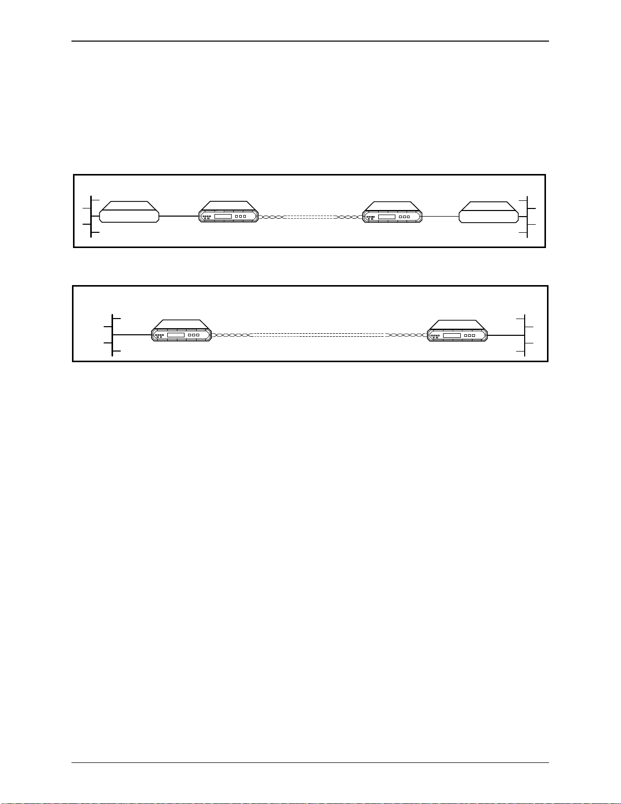
• Ethernet 10BaseT interface. The interface can use unshielded and shielded
twisted pair (UTP and STP) media. The ASMi-450 also includes a remote
bridge, that can be enabled/disabled by the user.
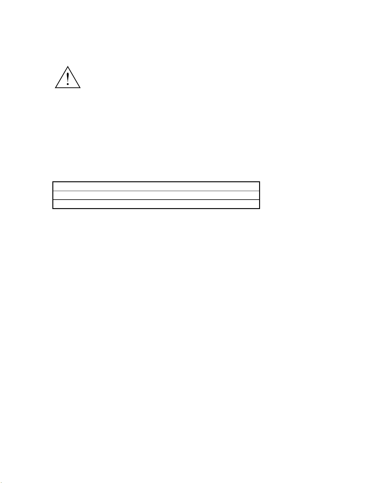
Figure 1-1 shows a typical application for an ASMi-450 with serial data
interface, and figure 1-2 shows a typical application for an ASMi-450 with
Ethernet interface.
LAN
BRIDGE
LOCAL
LAN
Serial Data Port
Characteristics
V.35
768kbps
ASMI-450
HDSL Line
V.35
768kbps
ASMI-450
Figure 1-A. Typical Application for ASMi-450 with Data Interface
HDSL Line
ASMI-450
ASMI-450
Figure 1-B. Typical Application for ASMi-450 with Ethernet Interface
The user's data port of the ASMi-450/768 and ASMi-450/1152 can be ordered
with the following interface options:
• V.35 interface: 34-pin female connector.
• X.21 interface: 15-pin D-type female connector.
• RS-530/RS-422 interface: 25-pin D-type female connector.
LAN
BRIDGE
REMOTE
LAN
• V.36/RS-422/RS-449 interface: a 37-pin D-type male connector is provided
by means of an adapter cable that connects to the RS-530/RS-422
connector.
The user's port interface has two timing options:
• Internal clock - the ASMi-450 user's port provides transmit and receive
clock to the equipment connected to the port.
• External clock - the equipment connected to the ASMi-450 provides the
transmit clock to the user's port, and the ASMi-450 returns a receive clock
locked to the external transmit clock.
Ethernet Interface
Characteristics
The Ethernet interface has a 10BaseT interface complying with the IEEE 802.3
standard, and is terminated in an RJ-45 shielded connector, which can operate
over UTP and STP media.
1-2 ASMi-450 Installation and Operation Manual
Page 21

Introduction
The interface includes a full-feature remote bridge, that operates at the physical
and data link layers of the OSI model, and is therefore completely transparent to
higher level protocols, such as TCP/IP, DECnet, XNS, ISO, and to operating
systems, such as NetWare, VINES, and 3COM+.
The bridge operates as a media access (MAC) layer remote bridge with selflearning capabilities: it learns and automatically recognizes the addresses of the
nodes attached to the local LAN (the LAN directly attached to the ASMi-450
interface), and uses this information to filter the LAN traffic. The address
information is stored in tables, which can store up to 10,000 addresses. The
address information is automatically updated (aging time is 5 minutes, that is, if
no frames are received from a node for 5 minutes, the node address is
automatically removed from the tables to ensure that only fresh addresses are
used).
Therefore, the bridge blocks the packets addressed to local nodes, and forwards
through the ASMi-450 link only multicasts, broadcasts, and packets addressed
to nodes attached to the remote LAN. To increase transmission efficiency, the
bridge compresses short packets by automatically recognizing the padding bits
in 64-bit frames, transmitting only the payload, and reconstructing the packets
at the remote end.
HDSL Subsystem
Characteristics
The filtering and forwarding can be performed at a rate of up to 15,000 packets
per second (provided the bandwidth selected on the HDSL link is sufficient to
carry the resulting payload rate).
When bridging is not necessary, e.g., for LAN extender applications, the user
can disable the bridge: in this case, the ASMi-450 operates as a repeater that
transfers transparently all the traffic to the remote end.
The ASMi-450 HDSL subsystem uses duplex transmission over one 2-wire line.
The ASMi-450 can operate on unloaded AWG-22, AWG-24, and AWG-26
twisted-wire pairs, and other similar pairs. Up to two bridged taps, having a
length of up to 500 meters, are tolerated.
The HDSL line interface is terminated in an RJ-45 eight-pin connector.
The line code on the HDSL lines is 2B1Q at a symbol rate approximately equal
to half the maximum data rate:
• ASMi-450/768: 392 kbaud
• ASMi-450/1152: 584 kbaud.
The increased symbol rate is used to provide framing and synchronization, and
an embedded operations channel, which enables end-to-end system management
and supervision.
The HDSL subsystem operates in a master-slave mode:
• The central unit, located at the central office side of the link, which serves
as the line termination unit (LTU), controls the system start-up procedure,
and provides the timing reference for HDSL line transmission.
ASMi-450 Installation and Operation Manual 1-3
Page 22
Introduction
• The remote unit, located at the remote end of the link (customer side),
serves as the network termination unit (NTU).
The ASMi-450 supports both the central (LTU) and the remote (NTU) operating
modes; the actual operating mode (LTU or NTU) is user-selectable.
System Timing
The ASMi-450 offers selectable timing options, which enable the distribution of
timing over the HDSL system, from the central office to the remote end.
• ASMi-450 Unit Configured as Central Unit (LTU). The ASMi-450 unit
configured as central unit has two timing modes: external timing and
internal timing.
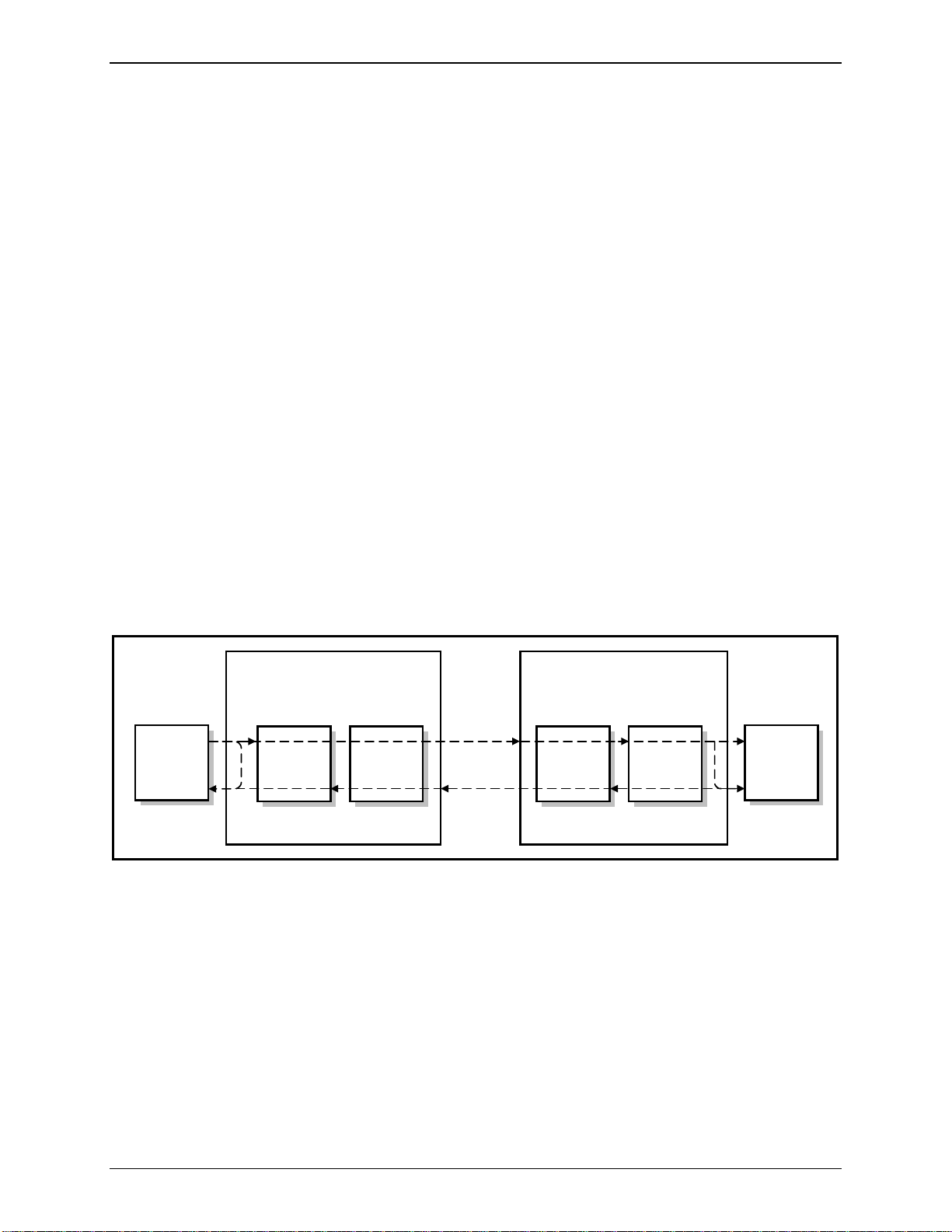
àExternal timing. With external timing, the ASMi-450 system timing is
locked to the clock signal received from the user's equipment (this mode
is not supported when the ASMi-450 is equipped with an Ethernet
interface). This mode allows locking the system timing to the timing of
the network to which the local ASMi-450 unit is connected, and thus it
enables providing the network timing to the equipment on the
customer's premises.
The local HDSL transmit timing is locked to the incoming clock signal,
therefore the transmit path of the local ASMi-450 transparently transfers
the timing from the user's equipment to the HDSL line.
Figure 1-3 shows the flow of timing signals through the ASMi-450 system in
the external timing mode.
CENTRAL ASMi-450
REMOTE ASMi-450
HDSL Line
Local
User's
DTE
Timing
Source
User
Interface
HDSL Line
Interface
HDSL Line
Interface
User
Interface
Figure 1-C. Flow of Timing Signals through ASMi-450 System in the External Timing Mode
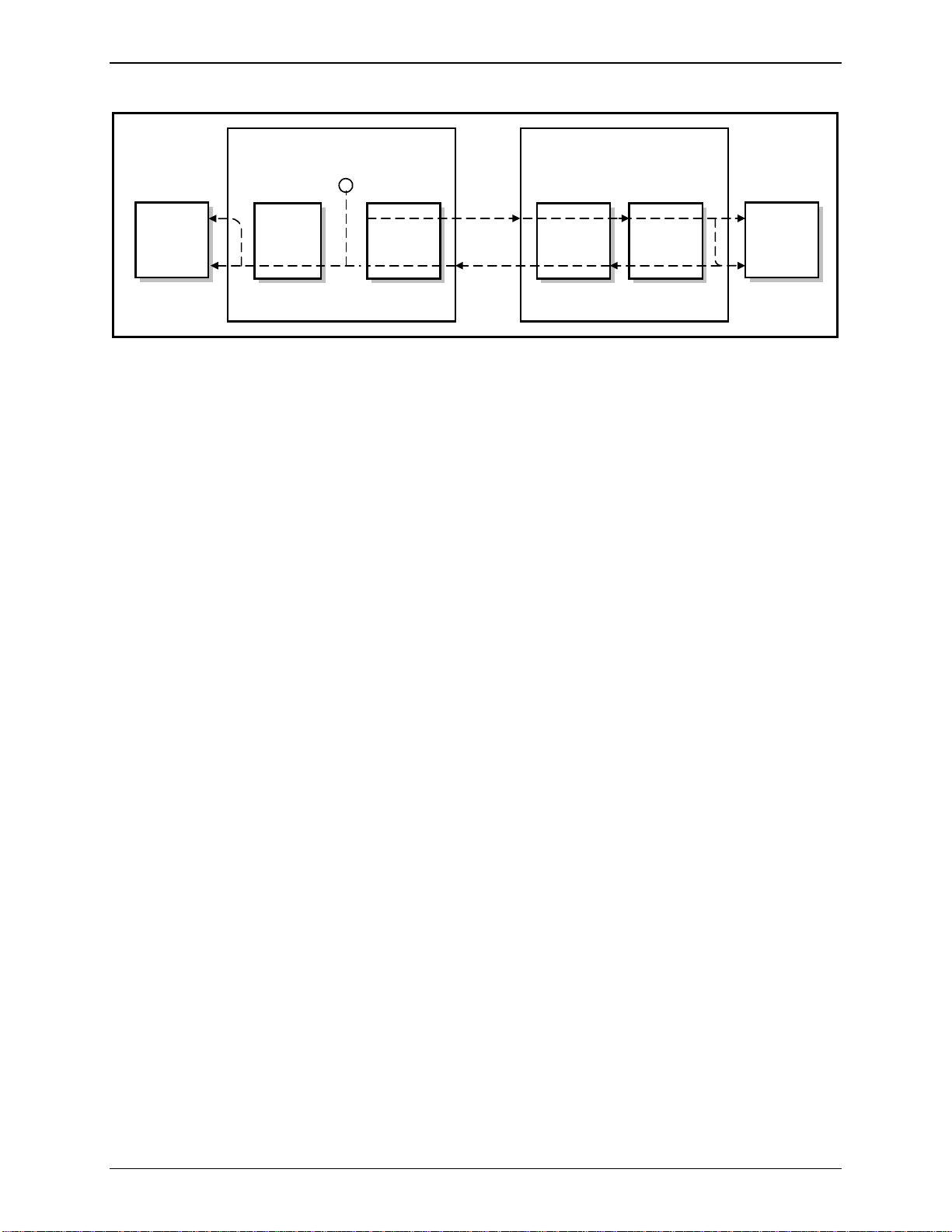
àInternal timing. With internal timing, the ASMi-450 system timing is
determined by the clock signal generated by an internal crystal
oscillator. This clock signal is supplied to the HDSL transmit path and
to the user's equipment.
The internal timing mode is suitable for point-to-point configurations.
Figure 1-4 shows the flow of timing signals through the ASMi-450
system in the internal timing mode.
Remote
User's
DTE
1-4 ASMi-450 Installation and Operation Manual
Page 23
Introduction
g
g
Local
User's
DTE
Timin
Source
Figure 1-D. Flow of Timing Signals through ASMi-450 System in the Internal Timing Mode
Control of
ASMi-450
Operation
CENTRAL ASMi-450
Internal
~
Timin
User
Interface
HDSL Line
Interface
HDSL
Line
REMOTE ASMi-450
HDSL Line
Interface
User
Interface
Remote
User's
• ASMi-450 Unit Configured as Remote Unit (NTU). The ASMi-450 unit
configured as remote unit always locks its internal system timing to the
incoming HDSL signal, which is received from the ASMi-450 unit
configured as central unit. The receive path of the ASMi-450 uses the
recovered timing to generate the data stream supplied to the equipment
connected to the remote user's port. Therefore, the receive path of the
remote ASMi-450 transparently transfers the timing from the HDSL line to
the remote user's equipment.
The ASMi-450 system is designed for unattended operation. The configuration
of the ASMi-450, that is, a complete collection of operating parameters, is
determined by a data base stored in non-volatile memory.
DTE
Local Control
The ASMi-450 can be controlled by means of a simple menu, operated by pushbuttons located on the front panel. During set-up, an LCD display guides the
operator in the execution of the desired operations. The display provides
information concerning the current system configuration and operating mode,
and the available values of each programmable parameter. In case of operator
errors, the ASMi-450 displays a message that explains the error and helps the
operator take the correct action.
Remote Management
In addition to front panel control, the ASMi-450 supports management from a
remote location. The remote management capabilities can be used to perform
the following activities:
• ASMi-450 configuration.
• Reading of ASMi-450 status.
• ASMi-450 testing.
• Display of alarm status and history.
ASMi-450 Installation and Operation Manual 1-5
Page 24

Introduction
The remote management functions are performed through a serial RS-232 port
that enables serial communication with a supervision terminal.
Using the supervision terminal functions, the user can also enable remote
management using IP communications, i.e., Telnet and SNMP. The IP
communication uses the Serial Link Internet Protocol (SLIP).
Note
Support for Telnet and SNMP is available for ASMi-450 with software version
1.0 and higher. If your ASMi-450 does not support Telnet and SNMP, contact
RAD Technical Support Department for upgrade information.
The remote management capabilities available through the serial RS-232 port
are as follows:
• Management by means of a Supervision Terminal. Any “dumb” ASCII
terminal connected to the RS-232 port of the ASMi-450 (or a PC running a
terminal emulation program), controlled by the program stored in the
ASMi-450, can be used as a supervision terminal. The control port can be
used to perform the following activities:
àASMi-450 configuration.
àReading of ASMi-450 status.
àASMi-450 testing.
àDisplay of alarm status and history.
The supervision terminal can communicate with the ASMi-450 using
either point-to-point, or polled (multidrop) communication. For polling
purposes, each ASMi-450 can be assigned an eight-bit address, for a
maximum of 255 nodes (the zero address is reserved for non-polled
communication).
As an option, a dial-up modem can be connected to the control port, to
provide call-in capabilities.
In addition to the remote management functions listed above, the
supervision terminal is also used for the preliminary configuration of
the ASMi-450, to enable the use of IP communication for Telnet and
SNMP management.
• Management by means of Telnet. The ASMi-450 also supports the Telnet
protocol, which enable remote management using the same command line
interface available with a supervision terminal. Telnet uses TCP/IP
communication through the RS-232 port of the ASMi-450.
• SNMP Management. The SNMP management capability enables fully
graphical, user-friendly management using the RADview network
management stations offered by RAD, as well as management by other
SNMP-based management systems.
1-6 ASMi-450 Installation and Operation Manual
Page 25

Introduction
Test and Diagnostics Capabilities
The ASMi-450 has comprehensive diagnostics capabilities. ASMi-450 models
with serial data port support the following types of test functions:
• Local loopback on the user's port of the local ASMi-450 (LOOP LOCAL
PORT).
• Remote loopback on the user's port of the remote ASMi-450 (LOOP REM
REM PORT).
These loopbacks may not be activated for an ASMi-450 equipped with Ethernet
interface, because this would cause a continuous state of collision on the LAN,
thereby disrupting the traffic on the LAN.
Maintenance is further enhanced by advanced self-test capabilities, and by an
automatically performed power-up self-test that provides circuit-level
diagnostics data.
Alarms
The ASMi-450 stores alarms detected during its operation in a buffer that can
hold up to 100 alarms. During regular operation, the front panel LCD display
shows if there are any alarms in the alarm buffer, to notify the local operator
that alarm conditions have been detected. The local operator can then review the
contents of the alarm buffer on the front panel display, and can delete old
alarms.
In addition to the alarm buffer, front-panel LED indicators display in real time
the activity on the ASMi-450 user's port, the state of the LAN, and the
synchronization status and transmission quality of the HDSL line, and alert
when test loops are present in the system.
Physical Characteristics
The ASMi-450 is a compact unit, intended for installation on desk tops or
shelves. Unit height is only 1U (1.75").
An optional rack-mount adapter kit enables the installation of one or two
ASMi-450 units in a 19" rack.
Power Requirements
The ASMi-450 can be powered by 115 VAC and 230 VAC, 47 to 63 Hz. As an
option, the ASMi-450 can also be ordered with a -48 VDC power supply.
ASMi-450 Installation and Operation Manual 1-7
Page 26
Introduction
1.2 Operating Environment
This section describes the HDSL environment, with special emphasis on the
implementation used in the ASMi-450 to provide the background information
required for understanding the configuration parameters of the ASMi-450
system.
Transmission
Media
HDSL Line Signal
HDSL systems are intended to operate on the local subscriber plant, which
typically uses a mixture of unshielded twisted-wire pairs. Moreover, it also
necessary to tolerate bridges taps. Therefore, HDSL systems must operate
properly on this media. The only requirement is that the lines must not be
loaded. In addition, it is assumed that the nominal impedance of the loops is
135 ohms, and that the loops are balanced with respect to ground.
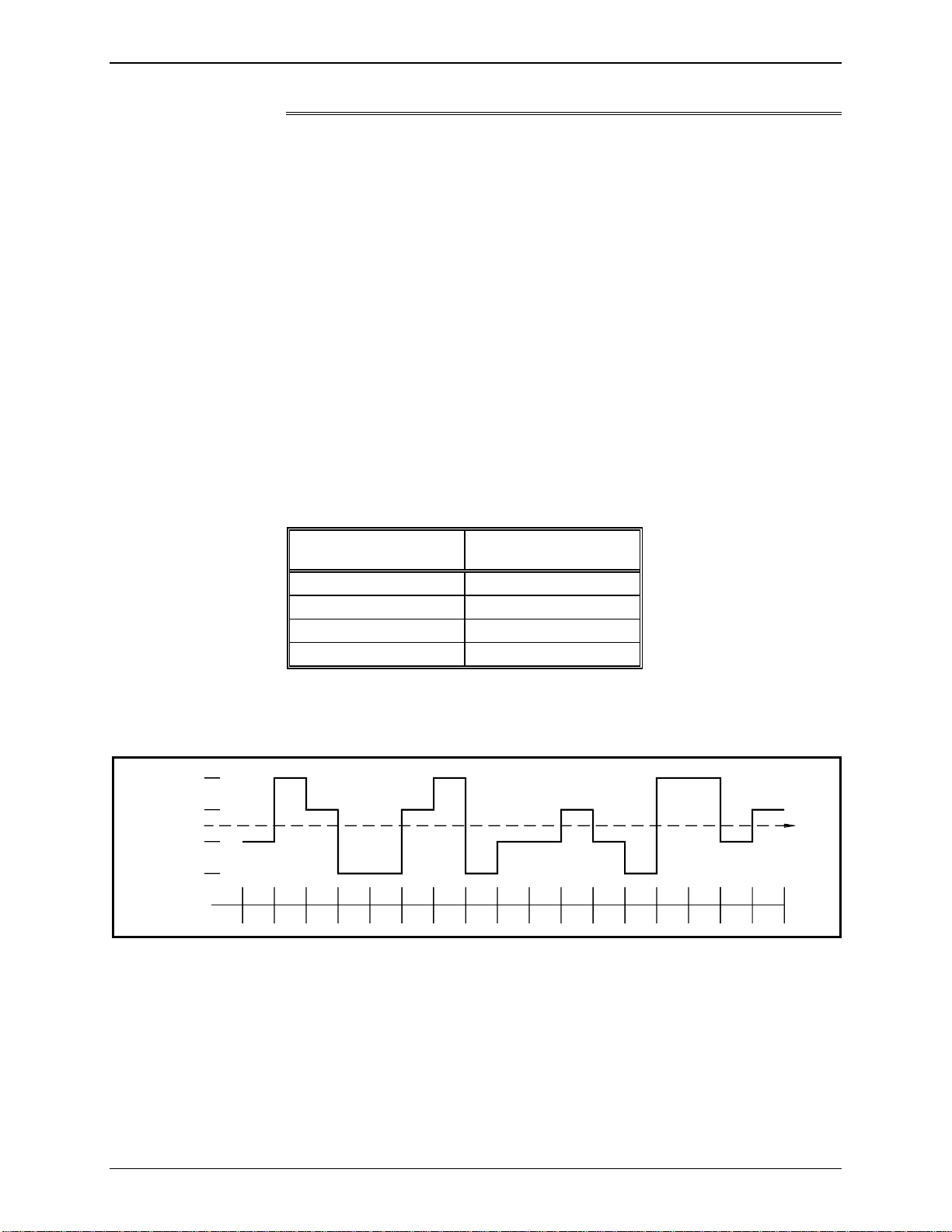
The line code on the HDSL loop is 2B1Q (2 Binary, 1 Quaternary). This is a
four-level pulse-amplitude modulation code without redundancy, under which
each pair of information bits is converted to a quaternary symbol, called quat
(bits can assume two signal levels, whereas quats have four levels).
The encoding rule of the 2B1Q code is as follows:
Binary Digits Quaternary Symbol
00 -3
01 -1
10 +3
11 +1
The levels of the quaternary signal are symmetrically located around the 0V,
and the nominal peak symbol level specified by the HDSL standards is 2.64V.
Figure 1-5 illustrates the 2B1Q encoding rule.
+3 (+2.64V)
+1 (+0.88V)
(0.00V)
-1 (-0.88V)
-3 (-2.64V)
Quats
Bits
-101+310+111-300-300+111+310-300-101-101+111-101-300+310+310-101+1
time
11
Figure 1-E. 2B1Q Encoding Rule
Due to the encoding of two bits into one symbol, the symbol rate on the HDSL
line is half the bit rate. Taking into consideration the highest payload rate
supported by the ASMi-450, 1152 kbps, and some overhead, the required line
data rate is 1168 kbps (equivalent to a symbol rate of 584 kbaud).
1-8 ASMi-450 Installation and Operation Manual
Page 27

Introduction
By reducing the line symbol rate, the maximum range that can be reached is
increased. This is achieved by offering several versions of ASMi-450, each
operating up to a given maximum rate. Together with the advanced digital
signal processing techniques implemented in HDSL systems, this results in a
robust data transmission system that can reliably operate over regular
unconditioned local loops.
HDSL Signal
Structure
HDSL-Related
System Functions
The HDSL signal is organized in frames. The HDSL frames carry user data,
framing and synchronization data, and overhead data. The overhead data is used
for a supervision and management channel, called embedded operations channel
(EOC) that serves for status transfer, diagnostic loopbacks and tests, etc.
The HDSL subsystem performs the following main functions:
• Mapping of input data bits into frames.
• Start-up process.
• Frame alignment.
• System management by means of the EOC channel.
To achieve proper operation, one of the unit<F14P11>s serves as the master that
controls the system start-up procedure, provides the timing reference for HDSL
loop transmission, and manages the communication on the EOC channel. The
master unit is called line termination unit (LTU) and is located at the central
office side of the link; the other unit is called network termination unit (NTU)
and is located at the remote end of the link.
The transmission of data on the HDSL loop is full duplex. To enable duplex
transmission, HDSL transceivers use an echo canceller, based on advanced
digital signal processing (DSP) techniques. When starting system operation, the
echo canceller is “trained”, to enable the separation of the received signal from
the transmit signal. The training is performed by transmitting a special sequence
for a predetermined period. This process is called “start-up process”; data
transmission can start only after its successful completion.
ASMi-450 Installation and Operation Manual 1-9
Page 28

Introduction
1.3 Technical Specifications
HDSL Interface
Signal Format 2B1Q line coding
Line Type One unconditioned, unloaded twisted pair
Nominal Impedance 135Ω
Transmit Pulse Shape Per ANSI T1E1.4/92-002RI and ETSI ETR-152
Transmit Signal Power +13 dBm
35 dB max. at 200 kHz (392 kbaud)
Loop Loss
Typical Range (AWG 24 Wire (0.5 mm))
392 kbaud 5.7 km
584 kbaud 4.5 km
−
31 dB max. at 150 kHz (584 kbaud)
−
16 dB minimum, 40 kHz to 200 kHz @ 392 kbaud
Return Loss (Relative to 135Ω)
Loop Loss
Noise Margin
Equalizer Automatic adaptive equalizer
Connector RJ-45
User's Serial Data Port Interface
Interface Type V.35, V.36/RS-422, RS-530, or X.21, in accordance with
Bit Rates
ASMi-450/768 n×64 kbps, up to 768 kbps
ASMi-450/1152 n×64 kbps, up to 1152 kbps
Interface Connectors
V.35 34-pin, female
−
16 dB minimum, 25 kHz to 317 kHz @ 584 kbaud
−
35 dB maximum at 200 kHz (392 kbaud)
−
31 dB maximum at 150 kHz (584 kbaud)
−
6 dB at 392 kbaud
−
3.3 dB for 584 kbaud
−
order
RS-530 25-pin D-type, female
RS-449/V.36 37-pin D-type, female (via adapter cable)
X.21 15-pin D-type, female
1-10 ASMi-450 Installation and Operation Manual
Page 29

Ethernet Interface
Compliance IEEE 802.3
Interface Type 10BaseT for use on UTP and STP media
Interface Connector RJ-45 shielded eight-pin connector
Internal Bridge Remote MAC-layer bridge with self-learning
Indicators
−
User's Serial Data Port
Ethernet Port
HDSL Line
Transmit Data (TD)
−
Receive Data (RD)
−
Link status
−
Collision indicator
−
Transmit and receive data activity
−
LOS (loss of synchronization)
−
QLTY (good quality)
Introduction
−
Status
Diagnostics
Loopbacks
Timing Modes
Central Unit
Remote Unit Loopback timing, derived from incoming HDSL receive
Front Panel Controls
LCD 2×16 characters
Push-buttons CURSOR, SCROLL, ENTER
Control Port
TEST
−
ALARM
−
Local loopback on the user's serial data port of the local
ASMi-450
−
Remote loopback on the user's serial data port of the
remote ASMi-450
−
Internal timing, derived from local oscillator
−
External timing, locked to user's port receive clock
clock
Interface ITU-T Rec. V.24/EIA RS-232, asynchronous DCE interface
for direct connection of control terminal
Data Rate 300, 1200, 2400, 9600, with Autobaud option
ASMi-450 Installation and Operation Manual 1-11
Page 30

Introduction
−
Word Format
Connector 9-pin D-type, female
Physical Characteristics
Depth 243 mm (9.5")
Width 215 mm (8.5")
Height 43 mm (1.7")
Weight 1.5 kg (3.5 lb.)
Power
AC Source 110V to 240VAC, 47 to 63 Hz, 5W
One start bit
−
7 or 8 data bits
−
Parity: none, odd, or even
−
One stop bit
DC Source -48VDC
Environment
Operating Temperature 0 to 50°C (32 to 122°F)
Relative Humidity Up to 90%, non-condensing
1-12 ASMi-450 Installation and Operation Manual
Page 31

Chapter 2
Installation
2.1 General
The ASMi-450 is delivered completely assembled. It is designed for installation
as a desk-top unit or for mounting in a 19" rack.
Mechanical and electrical installation procedures for the ASMi-450 are
provided in the following paragraphs. For rack installation instructions, refer to
Appendix C.
After installing the unit:
• Refer to Chapter 3 for system configuration information and procedures
using the front panel controls.
• Refer to Chapter 4 for system configuration procedures using an ASCII
terminal connected to the ASMi-450 control port.
In case a problem is encountered, refer to Chapter 5 for test and diagnostics
instructions.
Warning
No internal settings, adjustment, maintenance, and repairs may be
performed by either the operator or the user; such activities may be
performed only by a skilled technician who is aware of the hazards
involved.
Always observe standard safety precautions during installation, operation,
and maintenance of this product.
ASMi-450 Installation and Operation Manual 2-1
Page 32

Installation
2.2 Unpacking
A preliminary inspection of the equipment container should be made before
unpacking. Evidence of damage should be noted and reported immediately.
Unpack the equipment as follows:
• Place the container on a clean flat surface, cut all straps, and open or
remove top.
• Take out the ASMi-450 carefully and place it securely on a clean surface.
• Inspect the product for damage. Report immediately any damage found.
2.3 Site Requirements
Power
User's Port
Connections
HDSL Line
Connections
AC-powered ASMi-450 units should be installed within 1.5m (5 feet) of an
easily-accessible grounded AC outlet capable of furnishing the nominal supply
voltage (115 or 230 VAC, in accordance with your order).
DC-powered ASMi-450 units require a -48 VDC power source.
The user's port connector, designated DCE, depends on the interface type
installed on the unit:
• V.35 interface: 34-pin female connector.
• X.21 interface: 15-pin D-type female connector.
• RS-530/RS-422 interface: 25-pin D-type female connector.
• V.36/RS-422/RS-449 interface: a 37-pin D-type male connector is provided
by means of an adapter cable that connects to the RS-530/RS-422
connector.
• Ethernet interface: shielded RJ-45 connector (supports both UTP and STP
media).
Appendix A provides information on the pin allocation of the user's port
connectors, and for the adapter cable.
The HDSL line of the ASMi-450 is terminated in an RJ-45 connector. Appendix
A provides the pin allocation for this connector.
Front and Rear
Panel Clearance
Ambient
Requirements
2-2 ASMi-450 Installation and Operation Manual
Allow at least 90 cm (36 inches) of frontal clearance for operator access. Allow
at least 10 cm (4 inches) clearance at the rear of the unit for interface cable
connections.
The ambient operating temperature of the ASMi-450 should be 32 to 122°F (0 to
50°C), at a relative humidity of up to 90%, non-condensing.
Page 33

2.4 ASMi-450 Configuration Information
Installation
General
This paragraph provides information on the functions of the internal jumpers
and switches, to help in the selection of the correct setting for particular
application, and gives step-by-step instructions for performing the internal
settings. The default settings are also listed.
All the other configuration actions can be performed from the front panel or from
a control terminal, after the installation is completed. Information and detailed
instructions for these operations appear in Chapters 3 and 4, respectively.
Prior to ASMi-450 installation, it is necessary to check the positions of its
internal jumpers and switches. If necessary, change the settings in accordance
with the specific requirements of your application.
Warning - Electrical Shock Hazard
Access to the inside of the unit is permitted only to qualified and authorized
service personnel.
Disconnect the unit from the power line and from all the cables before
removing cover.
Line voltages are present inside the ASMi-450 when it is connected to
power and/or to the lines. Moreover, under external fault conditions
dangerous voltages may appear on the lines connected to the ASMi-450.
Any adjustment, maintenance, and repair of the opened instrument under
voltage should be avoided as much as possible and, when inevitable, should
be carried out only by a skilled technician who is aware of the hazard
involved. Capacitors inside the instrument may still be charged even after
the instrument has been disconnected form its source of supply.
Opening ASMi-450
Case
Caution
The ASMi-450 contains components sensitive to electrostatic discharge (ESD).
To prevent ESD damage, avoid touching the internal components, and before
moving jumpers, touch the ASMi-450 frame.
To reach the internal jumpers and switches of the ASMi-450, it is necessary to
open its case. The case cover is held by four screws, identified in figure 2-1.
After releasing the screws, the cover can be removed.
Use the following procedure:
• Disconnect all the cables connected to the ASMi-450.
• Refer to figure 2-1, turn the unit over, and unscrew the four cover screws.
Keep the screws in a safe place.
• After the four screws are released, remove ASMi-450 top cover by pulling
it straight up.
ASMi-450 Installation and Operation Manual 2-3
Page 34

Installation
Jumper and Switch
Location and
Functions
Figure 2-1.
Identification of Cover Screws
The ASMi-450 consists of a main board and a user's port interface board. The
jumpers and switches located on the ASMi-450 main board are identified in
figure 2-2. Their functions are described below.
In addition to the jumpers listed below, the ASMi-450 has additional jumpers,
that are set by the manufacturer and must not be changed by you.
Note
Figure 2-2 also indicates the location of the 1A protection fuses, F1 and F2,
used to protect the line side of the isolation transformers of the HDSL line.
The type of user's port interface board depends on the interface installed on your
ASMi-450. None of the user's port interface boards offered with the ASMi-450
includes user-selectable jumpers.
Switch S1
The ASMi-450 is delivered with a set of default parameters that allow the user
to start the configuration activities from a known state. These parameters are
stored in its program EPROM, and therefore cannot be modified. By
configuring the ASMi-450, the user specifies custom parameter values; these
parameter values are stored in the ASMi-450 data base (located in non-volatile
memory), and are automatically loaded each time the ASMi-450 is powered up.
Note
If during the power-up self-test, it is found that the user's configuration has
been corrupted, the ASMi-450 will automatically reload the default parameters
from its EPROM.
2-4 ASMi-450 Installation and Operation Manual
Page 35

Installation
Figure
ASMi-450 Installation and Operation Manual 2-5
. ASMi-450 Internal Settings
2-2
Page 36

Installation
DIP switch S1 allows the user to control the reloading of the desired group of
default parameters. The switch has four sections used for the following
purposes:
• Switch section DEF SP. This section selects the source of the control port
parameters:
ON ASMi-450 uses the default parameters stored in its program
EPROM. The default values are Autobaud, eight data bits,
and no parity.
OFF ASMi-450 uses the user-selected parameters.
Upon first-time operation, you should use the ON position to start the
configuration. You can select this position again to restart with the default
parameters in case the current values are not known, and it is not possible to
communicate with the ASMi-450 through its control port.
The ASMi-450 is shipped with this section set at OFF.
• Switch section DB INT. This section selects the source of the data base
configuration parameters:
ON ASMi-450 uses the default parameters stored in its program
EPROM.
OFF ASMi-450 uses the user-selected parameters.
The ASMi-450 is delivered with the data base loaded with the default
parameters. You can select this position again to restart with the default
parameters in case the current values are not known.
The ASMi-450 is shipped with this section set at OFF.
• Switch section MS/SV. This section is reserved for future features, and
must be always set at ON.
The ASMi-450 is shipped with this section set at ON.
• Switch section PSWD. A password, consisting of up to eight alphanumeric
characters, can be used to prevent unauthorized personnel from using the
ASMi-450 control program. The ASMi-450 is delivered with a default
password, ASMI, but normally the password is selected by the user.
The PSWD section is used to select between the default ASMi-450
password (the ON position) and the user-selected password (the OFF
position). The ASMi-450 address (node number) is also affected by the
setting of the PSWD section: with the jumper set at ON, the node number is
set to 0.
Upon first-time operation, you should use the ON position to start the
configuration. You can select this position again to restart with the default
password and node address 0 in case the current user password was lost.
The ASMi-450 is shipped with this section set at OFF.
2-6 ASMi-450 Installation and Operation Manual
Page 37

Installation
Note
User-selected parameter values are not erased by setting one or more switch
sections to ON: this action merely causes the ASMi-450 to use the default
values. However, if the ASMi-450 is turned off and then powered up again, the
default values replace the user values.
Jumper R/C
The jumper designated R/C, is used to select the function of the ASMi-450 unit:
C The ASMi-450 unit operates as a central unit (LTU).
R The ASMi-450 unit operates as a remote unit (NTU).
The ASMi-450 shipped with the jumper set at C.
Jumper FGND/GND
The jumper FGND/GND controls the connection between the ASMi-450 signal
ground and the frame (chassis) ground.
Internal Settings
Procedure
Reinstalling
ASMi-450 Cover
YES Signal ground is connected to the frame (chassis) ground.
NO Signal ground is not connected to the frame ground.
The ASMi-450 is shipped with the jumper set at YES (connected).
Setting the jumper to NO may invalidate the safety of connection to
telecommunication networks in certain locations, where permanent excessive
voltages are present on the lines.
Refer to figure 2-2, and identify jumper and switch locations and settings.
Change settings as required.
After completing the internal settings, reinstall the top cover as follows:
• Position the lower half of the ASMi-450 case on a flat, clean surface.
• Check that the decorative black plastic strips on the sides on the unit are still
in place (if not, place the strips in the grooves on the sides of the lower
half).
• Identify the front and rear of the top cover, and position the cover on the
lower half of the ASMi-450, so that the cover guides are located just above
the holes in the lower half. Close the cover and ensure that the protruding
tips of the cover guides enter the corresponding recesses in the lower half.
• Hold the cover in place, and turn the assembly over, to gain access to the
bottom of the unit.
• Insert the original cover screws in their positions and tighten carefully. Do
not use excessive torque.
ASMi-450 Installation and Operation Manual 2-7
Page 38

Installation
2.5 Connections
Connector
Location
Figure 2-3 shows typical rear panels of ASMi-450 units, and identifies
connector locations:
• Figure 2-3.A shows the rear panel of an AC-powered ASMi-450 unit (the
unit shown in this figure has an RS-530 interface).
• Figure 2-3.B shows the rear panel of a DC-powered ASMi-450 unit (the
unit shown in this figure has an Ethernet interface; for an explanation of the
indicator functions, refer to Chapter 3).
Grounding
A. Typical AC Powered Unit
B. Typical DC-Powered Unit
Figure
Any interruption of the protective (grounding) conductor (inside or outside the
instrument) or disconnecting the protective earth terminal can make this
instrument dangerous. Intentional interruption is prohibited.
. Typical ASMi-450 Rear Panels
2-3
2-8 ASMi-450 Installation and Operation Manual
Page 39

Installation
Warning
Before switching on this instrument and before connecting any other cable,
the protective earth terminals of this instrument must be connected to the
protective ground conductor of the (mains) power cord. The mains plug
shall only be inserted in a socket outlet provided with a protective earth
contact. The protective action must not be negated by use of an extension
cord (power cable) without a protective conductor (grounding).
Make sure that only fuses with the required rated current, as marked on
the ASMi-450 rear panel, are used for replacement. The use of repaired
fuses and the short-circuiting of fuse holders is forbidden. Whenever it is
likely that the protection offered by fuses has been impaired, the instrument
must be made inoperative and be secured against any unintended
operation.
Power Connection
User's Port
Connections
Before starting, check that the ON/OFF switch on the ASMi-450 rear panel is
set to OFF.
AC Power Connection
Skip this section if the ASMi-450 is powered from a DC source.
AC power should be supplied to the ASMi-450 through the 5 feet (1.5m)
standard power cable terminated by a standard 3-prong plug.
First, connect the power cable to the connector on the ASMi-450 rear panel, and
then to the mains outlet.
DC Power Connection
Skip this section if the ASMi-450 is powered from an AC source.
Connect the power cable to the DC power connector, and then connect the other
end to the DC distribution panel. Pay attention to correct polarity.
The connection to the user's equipment is made to the rear panel connector
marked DCE. The interface type installed in the ASMi-450 is indicated by the
label located above the DCE connector (for example, figure 2-3.A shows a
ASMi-450 rear panel with RS-530 interface).
V.35 Interface The V.35 interface has a 34-pin female connector,
wired for direct connection to V.35 DTE interfaces.
X.21 Interface The X.21 interface has a 15-pin D-type female
connector, wired for direct connection to X.21 DTE
interfaces.
RS-530 Interface The RS-530 interface has a 25-pin D-type female
connector wired for direct connection to
RS-530/-RS-422/V.24 DTE interfaces.
V.36 Interface If the required interface is V.36/RS-449/422, connect
ASMi-450 Installation and Operation Manual 2-9
Page 40

Installation
first the interface adapter cable to the RS-530
connector, then connect the user's data cable to the
37-pin D-type male connector at the other end of the
adapter cable.
Ethernet Interface The Ethernet interface has an RJ-45 connector for
direct connection to Ethernet 10BaseT LAN's.
Connector pin allocations and adapter cable wiring data appear in Appendix A.
HDSL Line
Connections
Control Port
Connection
The HDSL lines connect to the RJ-48C connector designated NETWORK
HDSL.
Connect a cable prepared in accordance with Appendix A between the control
port connector, designated CONTROL DCE, and the control terminal. If the
control terminal is connected via modems, use a cross-over cable.
Note
The various user interface cables should be shielded, in order to comply with
FCC rules. The ASMi-450 and its data interfaces will work well even if the
cables are not shielded, but some radio interference may occur.
2-10 ASMi-450 Installation and Operation Manual
Page 41

Chapter 3
Front-Panel Operating
Instructions
3.1 Scope
In this chapter you will find detailed instructions for operating the ASMi-450
from the front panel. The information presented in this chapter includes:
• ASMi-450 front panel - Section 3-2.
• General description of ASMi-450 control, display and push-button
functions, and menu organization - Section 3-3.
• ASMi-450 configuration parameters - Section 3-4 and 3-5.
• ASMi-450 operating procedures (turn-on, front-panel indications, and turn-
off) - Section 3-6.
• ASMi-450 local configuration set-up - Section 3-7.
• ASMi-450 configuration error messages - Section 3-8.
Refer to Chapter 4 for instructions on the use of a control terminal to remotely
control and monitor ASMi-450 operation.
ASMi-450 Installation and Operation Manual 3-1
Page 42

Front-Panel Operating Instructions
3.2 Front Panel Controls, Connectors, and Indicators
Figure 3-1 shows the front panel of the ASMi-450. Table 3-1 lists the functions
of the ASMi-450 controls, connectors and indicators, located on the ASMi-450
front panel. The index numbers in Table 3-1 correspond to the item numbers in
figure 3-1.
Figure 3-A. ASMi-450 Front Panel
Table 3-A. ASMi-450 Controls, Connectors and Indicators
No. Control or Indicator Function
1 TD indicator Lights to indicate activity on the transmit line of the local DCE port.
2 RD indicator Lights to indicate activity on the receive line of the local DCE port.
3 LOS indicator Lights when the HDSL line circuits lose synchronization to the incoming
signal
4 QLTY indicator Lights when the far-end HDSL block error (FEBE) rate reported by the
remote equipment is less than 10-7 (good quality)
5 ALM indicator Lights when alarms are stored in the ASMi-450 alarm buffer
6 TST indicator Lights when a test is active
7 Alphanumeric display Liquid crystal display (LCD) used to display messages and status
information. The display contains 2 rows of 16 characters each
8 CURSOR push-button Used to move among the information fields
9 SCROLL push-button Used to scroll among the available options of the displayed functions
10 ENTER push-button Used to enter the changes made in the ASMi-450 operation, and initiate
operation under the new set-up
3-2 ASMi-450 Installation and Operation Manual
Page 43

Front-Panel Operating Instructions
Ethernet Interface
Indicators
Figure 3-2 shows the indicators located on the rear panel of an ASMi-450 unit
with Ethernet interface, and Table 3-2 explains the functions of the Ethernet
interface indicators.
1 2
4 3
Figure 3-B. ASMi-450 Rear Panel (Ethernet Interface)
Table 3-B. Ethernet Interface Indicators
No. Indicator Function
1 LINK indicator Lights when the Ethernet interface is connected to an active LAN (i.e., a LAN
with at least one active station)
2 RX indicator Lights when receive activity is present on the Ethernet interface
3 TX indicator Lights when transmit activity is present on the Ethernet interface
4 COLL indicator Lights momentarily for each collision
ASMi-450 Installation and Operation Manual 3-3
Page 44

Front-Panel Operating Instructions
3.3 Control of ASMi-450 Operation, General
General
ASMi-450 operating mode is determined by a set of parameters stored in an
internal non-volatile memory. These parameters are selected by the user, using
the ASMi-450 front panel push-buttons, a supervision terminal, or a network
management station (either a generic SNMP management station, or the
RADview management station offered by RAD). When a supervision terminal,
or a network management station is in control, the ASMi-450 cannot be
controlled from the front panel; however, when under the control of a network
management station, the front panel can still be used to read the current
parameters, status, and statistics.
After the operating parameters have been selected, a process called
configuration set-up, the ASMi-450 no longer requires operator attendance. The
configuration stored in the ASMi-450 memory is not affected when power is
turned off.
Upon turn-on, the ASMi-450 checks the validity of the stored configuration
data, and if everything is OK, it assumes the last selected configuration.
• If the configuration does not require modification, the ASMi-450 is then
ready for operation immediately after power is applied.
• If the configuration data is not valid, the ASMi-450 lets you load instead a
default configuration. The default configuration, prepared by the
manufacturer, is stored in the program EPROM.
General Operating
Instructions
Display Functions
All operations are performed using an interactive, menu-driven user-friendly
interface. The interface is controlled by means of the display and three pushbuttons. The ASMi-450 guides you in the execution of the required task by
means of simple and clear messages, presents the range of available parameter
values and checks your inputs. Moreover, the ASMi-450 will present to you
only those parameter values available on your ASMi-450 model in the selected
operating mode.
If you make a configuration error, e.g., you select a parameter value that
conflicts with the current operating mode, the ASMi-450 rejects the erroneous
selection and displays an error message that identifies the error.
You will find detailed instructions for operating the ASMi-450 in Section 3-6
and 3-7. Section 3-8 explains the configuration error messages, and presents
instructions for correcting the problem.
The ASMi-450 display has the following functions:
• Display of status messages.
• Display of test functions.
• Display of configuration parameters.
3-4 ASMi-450 Installation and Operation Manual
Page 45

Front-Panel Operating Instructions
Status Messages
When the ASMi-450 is not being configured and no test is active, its display
shows status messages. The alarm buffer can store up to 100 alarms. The
presence of status messages in the alarm buffer is indicated by the ALM
indicator.
The status messages appear under the header ALARM BUFFER. The status
messages are described in Chapter 5.
Test Functions
The test functions include:
• Local and remote loopbacks on the user's port, for rapid isolation of faults.
• BER test (future option).
Note
Do not activate any loopback when using an ASMi-450 with Ethernet interface.
The test function messages appear under the header TEST OPTIONS.
Chapter 5 describes the available test functions.
Configuration Parameters
The ASMi-450 has two groups of configuration parameters:
• System parameters.
• Control port parameters.
The configuration parameter groups are detailed in the following chart.
Display Description See...
SYSTEM PARAMETER Display and selection of system parameters:
- Master clock source
- Selection of active time slots
SP PARAMETER Display and selection of ASMi-450 control port parameters:
- Data rate
- Number of data bits
- Parity
- Interface type
Sec. 3-4
Sec. 3-5
In addition to the parameters configured from the front panel, there are
parameters that can be controlled only via the control port. These are presented
in Chapter 4.
After configuration, if alarm messages are stored in its ALARM BUFFER and
no test is active, the ASMi-450 automatically returns to the display of alarm
messages.
ASMi-450 Installation and Operation Manual 3-5
Page 46

Front-Panel Operating Instructions
Organization of
ASMi-450 Display
Using Front-Panel
Push-buttons
The ASMi-450 display has two rows:
• Upper row. Shows the name of the displayed function, group of
configuration parameters, or test option.
• Lower row. The lower row displays:
àParameter name and value.
àStatus messages.
àLoopback status.
àError messages.
àDiagnostics messages.
ASMi-450 operation is controlled by means of the display and the three pushbuttons designated CURSOR, SCROLL and ENTER. The same control actions
are consistently used for all the activities:
CURSOR Use this push-button to indicate what you want to change.
Pressing the CURSOR push-button moves the cursor among
the fields in the current display. The cursor is a bar that
appears under first character of the selected field.
Some fields list several different items, and then you move
the cursor under the desired item. The item displayed above
the cursor can be changed (“scrolled”) by pressing
SCROLL.
SCROLL Press repeatedly to display the alternatives for the current
field/item indicated by the cursor. Holding the push-button
depressed causes automatic scrolling of the available
alternatives.
ENTER Press it once to select the value displayed in the field/item
indicated by the cursor.
• If the selected value is valid, it replaces the old value
and the change takes effect immediately.
• If you make an incorrect selection, the selection is not
accepted. In this case, you see a CONFIG ERROR
message with a two-digit code in the second display
row. The code indicates what is wrong. After a short
time, the error message disappears and you see again
the original display. Now you can correct the error.
Section 3-8 explains the error codes and what to do to
correct the error.
The ENTER key has an additional function: when the alarm buffer is displayed,
the ENTER key can be used to delete all the alarms in the buffer.
3-6 ASMi-450 Installation and Operation Manual
Page 47

Front-Panel Operating Instructions
If you make an incorrect selection, the selection is not accepted. In this case,
you see a CONFIG ERROR message with a code number. The code indicates
what is wrong. Section 3-8 explains the codes.
After a short time, the error message disappears and you see again the original
display. Now you can correct the error.
ASMi-450 Installation and Operation Manual 3-7
Page 48

Front-Panel Operating Instructions
3.4 System Configuration Parameters
Table 3-3 lists the available system configuration parameters and their
functions. The table also lists the parameter values included in the ASMi-450
default configuration.
Table 3-C. System Parameters
Designation Function Values
CLK MASTER
ACTIVE TS
ETHERNET MODE
BRIDGING
Selects the master timing reference.
The available selections depend on
the ASMi-450 function. Refer to
Section 1-2 for details
Determines the number of active
HDSL time slots, which determines
user's data rate.
The maximum number of active
time slots depends on the ASMi450 model:
- ASMi-450/768: 12 time slots
- ASMi-450/1152: 18 time slots
Selects the Ethernet LAN traffic
transfer mode (displayed only for
ASMi-450 version with the
Ethernet interface)
Selects the Ethernet traffic control
function (displayed only for
ASMi-450 version with the
Ethernet interface)
ASMi-450 configured as central (CNTR) unit:
EXT Locked to the clock signal provided by the
user's equipment (this locks the HDSL
transmit timing to the timing of the incoming
user's signal).
INT Internal oscillator.
Default: EXT
ASMi-450 configured as remote (REM) unit:
Always locked to the recovered receive clock of the
HDSL line. This locks the user's equipment timing to
the timing of the HDSL signal.
The number of time slots can be set from 1 up to the
maximum supported by the corresponding ASMi-450
model
Default: Maximum number of time slots supported
by the corresponding ASMi-450 model
HALF Half duplex operation
FULL Full duplex operation
Default: HALF
FILTER The internal bridge of the ASMi-450 is
enabled, and filters the traffic transferred to
the remote end
TRANS The internal bridge of the ASMi-450 is
disabled, and the Ethernet traffic is
transparently transferred (LAN extender
function)
Default: FILTERED
3-8 ASMi-450 Installation and Operation Manual
Page 49

Front-Panel Operating Instructions
3.5 Control Port Configuration Parameters
Table 3-4 lists the available control port configuration parameters and their
functions. The table also lists the parameter values included in the ASMi-450
default configuration.
In addition to the parameters listed below, the ASMi-450 supports additional
parameters, which can be modified only via the control port. These parameters
are explained in Chapter 4.
Table 3-D. Control Port Parameters
Designation Function Values
SPEED BPS
DATA
PARITY
INTERFACE
Selects control port
data rate
Selects the number of
data bits in the word
format
Controls the use of
parity
Selects control port
interface
300,
1200,
2400, Control port data rate (bps)
4800,
9600
AUTO Autobaud operation. The ASMi-450 automatically
identifies the control port data rate.
To enable positive identification the transmission must
start with three consecutive Carriage Returns.
Default: AUTO
7 or 8 data bits.
Default: 8
ODD Odd parity
EVEN Even parity
NONE Parity disabled (only available with 8 data bits)
Default: NONE
DCE The ASMi-450 appears as a DCE for the control terminal
DTE The ASMi-450 operates as a DTE for connection via
modem to the control terminal (future option)
Default: DCE
AUX DEV
ASMi-450 Installation and Operation Manual 3-9
Selects an auxiliary
device
TERMINAL Management by means of supervision terminal
NMS-SLIP Management by means of TCP/IP over SLIP
(Telnet or SNMP)
NONE Not in use
Default: TERMINAL
Page 50

Front-Panel Operating Instructions
3.6 Operating Instructions
This paragraph covers the following activities:
• Turn-on
• Checking ASMi-450 configuration
• Normal ASMi-450 operating indications
• ASMi-450 turn-off.
Refer to Section 3-7 for local configuration set-up instructions.
Turn-on
To turn the ASMi-450 on, set the rear POWER switch to ON. Upon turn-on, the
ASMi-450 performs self-test: observe the front-panel indications.
During the self-test, the ASMi-450 displays the software version in the format X.Y:
ASMi-450 REV: X.Y
SELF TEST
After successfully completing the self-test procedure, the ASMi-450 will switch
to the default display - the ALARM BUFFER.
Notes
1. If the ASMi-450 fails the self-test, you will see a description of the fault in
the second row. In this case, the ASMi-450 must be repaired before it can be
used again. Refer to Chapter 5 for instructions.
2. If the configuration data stored by the ASMi-450 is corrupted, the
DATABASE CKS ERR alarm message is generated. In this case, it is
necessary to initialize the data base (after initialization, you can select again
the desired parameters). To initialize the data base, set section DB INIT of
the internal switch S1 to ON, turn the ASMi-450 on, and then turn it off and
return the switch section to OFF (refer to Chapter 2 for detailed
procedures).
The parameter values included in the default configuration are listed in
Section 3-4 and 3-5.
You can verify the ASMi-450 configuration as explained below. If the
configuration does not require modification, the ASMi-450 is ready for
operation immediately after self-test is completed. To change the configuration,
refer to Section 3-7.
Checking Current
Operating
Review Section 3-4 and 3-5 for an explanation of the ASMi-450 configuration
parameters.
Configuration
Note
During the following procedure, do not press the ENTER push-button, to
prevent accidental change of parameters.
3-10 ASMi-450 Installation and Operation Manual
Page 51

Front-Panel Operating Instructions
Step Action Key Display
1 Bring the cursor under the top row (if not
already there)
2 Scroll to display SYSTEM PARAMETER in
the top row
3 Bring the cursor under the left-hand field in
the second row
4 Scroll to see the other system parameters SCROLL After each pressing of the SCROLL button,
5 Bring the cursor under the right-hand field in
the top row
6 Bring to display the next group of
configuration parameters (the control port
parameters, SP PARAMETER)
7 Repeat steps 3 and 4 to display the control
port parameters - SP PARAMETER
Normal Indications
This section explains the indications provided on the front-panel LCD and the
CURSOR
SCROLL Second row shows the first system parameter,
CLK MASTER, and its current selection
CURSOR
the second display row shows the current
value of the next system parameters.
Continue until CLK MASTER appears again
CURSOR
CURSOR,
SCROLL
CURSOR,
SCROLL
indicators of the ASMi-450.
Display
The normal message displayed in the top row is ALARM BUFFER. However,
if no alarm is stored in the alarm buffer (ALM indicator off), the ASMi-450 will
continue displaying the last user-selected display.
In addition, the ASMi-450 will automatically abort the current activity and will
redisplay the ALARM BUFFER message if no front-panel button is pressed for
1 minute, thereby ensuring that it will not remain in an indeterminate state even
if the operator does not complete a configuration activity.
When the top row shows ALARM BUFFER, the second row displays the
following information:
•
During normal operation, the second row should show EMPTY (no alarm
messages).
•
If the alarm buffers contains alarms, you will see SCROLL in the left-hand
field of the second row, and CLEAR in the right-hand field.
The alarms can be displayed by bringing the cursor under SCROLL, and then
pressing ENTER: you can now scroll between the alarms stored in the alarm
buffer.
To interpret the alarm messages displayed in the second row, refer to Table 5-1.
ASMi-450 Installation and Operation Manual 3-11
Page 52

Front-Panel Operating Instructions
In Table 5-1, you will find two types of alarms, designated as ON/OFF and ON:
• A message indicating an ON/OFF alarm is displayed only when the alarm
condition is present, and is automatically removed when the condition is
cleared (if the alarm is being displayed, it will disappear only when the
display is refreshed by scrolling).
• A message indicating an ON alarm persists even after the event that caused
the alarm condition is cleared.
If the ASMi-450 operates normally, but an alarm message of the ON type is
displayed, you can clear the event alarm message from the display by the
following procedure:
Step Action Key Display
1 Bring the cursor in the second row, under
CLEAR
2 Press ENTER to clear the event messages in
the alarm buffer
Normal Front-Panel Indications
During normal operation, all the ASMi-450 front-panel indicators are off.
Ethernet Interface Indications
During normal operation, the LINK indicator must light continuously. The
COLL, TX, and RX light according to LAN traffic conditions.
Fault Indications
If the LOS indicator and/or the TST indicator lights, data transfer is interrupted.
• The TST indicator lights when a test is active. If the test is activated from
the local ASMi-450, you can see the test type by entering the TEST
OPTIONS (Chapter 5). You can disconnect a local or remote loop as
explained in Chapter 5.
• The HDSL LOS indicator lights when a local loss of synchronization alarm
condition is present on the corresponding line.
• When using the Ethernet interface, the rear LINK indicator will turn off if
the Ethernet LAN is not connected, or not operating properly.
CURSOR
ENTER If no state alarms are present, the second row
should show EMPTY
If the COLL indicator lights continuously, this indicates that a permanent
state of collision is present on the LAN. This may be caused by
malfunctioning LAN equipment, however it may also occur in case a test
loopback is activated on the ASMi-450. Check and deactivate any test
loopback on the local and remote ASMi-450 units.
Turn-off
For AC-powered ASMi-450 units, set the rear power switch to OFF.
For DC-powered ASMi-450 units, disconnect the power cable.
3-12 ASMi-450 Installation and Operation Manual
Page 53

Front-Panel Operating Instructions
3.7 Local Configuration Set-Up Procedure
Before starting any configuration action:
• Review the relevant configuration parameters given in Section 3-4 and 3-5.
• Obtain a list of the required parameters from your system administrator.
ASMi-450 configuration consists of the selection of the system parameters.
When a control terminal will be used to control the ASMi-450, you should also
select the parameters of the control port.
The general configuration procedure is explained on the following page. The
general procedure is followed by special considerations for each group of
parameters.
The ASMi-450 presents only those parameters available in the selected mode,
therefore it is important to perform the configuration according to the order
specified above.
Password
Protection
General
Configuration
Procedure
The ASMi-450 is intended for configuration via the control port, using an ASCII
terminal. If you cannot use a terminal for performing the configuration
procedures, it is necessary to configure the ASMi-450 from the front panel.
This, however, is possible only when the use of the password is disabled: if the
password is enabled, you can use the ASMi-450 front panel to display the
current parameter values, but cannot modify them. If you try to modify a
parameter, or to perform a test function, from the front panel when the password
is enabled, you will see CONFIG ERROR 5.
When the ASMi-450 uses the default parameters values, the use of the password
is disabled (to load the default parameters, use the DB INI section of the internal
switch S1, as explained in Section 2-4). The use of the password can be enabled
or disabled by means of the control terminal, by entering the DEF SP command
(refer to Chapter 4 for detailed instructions).
The following steps are used to perform any configuration activity:
Notes
1. Before starting the configuration procedure, always disconnect all the userinitiated loopbacks (select OFF on TEST OPTIONS).
2. Refer to Section 3-8 for an explanation of the configuration error messages
the ASMi-450 displays when you make an error.
ASMi-450 Installation and Operation Manual 3-13
Page 54

Front-Panel Operating Instructions
Step Action Key Display
1 Bring the cursor under the top row (if not
already there)
2 Scroll to display the desired group of
parameters in the top row
NOTE
When the desired group of parameters
must be independently selected for each
link, the top row includes an additional
field (at the rightmost side of the top
row): this field is used to select the
desired link number. In this case, use the
CURSOR key to bring the cursor to the
rightmost field, then SCROLL to show
the desired link number.
3 When the second row has more than one
field, bring the cursor under the left-hand
field (parameter name) in the second row,
and then scroll to display the desired
parameter in the selected group
4 Bring the cursor under the right-hand field
(the parameter value) in the second row
5 Scroll to set the required value for the
displayed parameter
6 When the desired parameter value is
displayed, select the new parameter value
NOTE
You must press ENTER after changing
parameters of a certain group, e.g.,
SYSTEM. If you change parameter
values, but return the cursor to the first
field and scroll to another group
without pressing ENTER, the changes
are discarded and you will see the
message CONFIG LOST.
7 Repeat steps 3 through 6 until values are
assigned to all the parameters in the group
8 Repeat steps 1 through 7 until values are
assigned to all the parameters in the desired
groups
CURSOR
SCROLL Second row shows the first parameter in the
selected group and its current value
CURSOR
SCROLL
CURSOR
SCROLL The second row shows the available values
ENTER The cursor returns to the first field in the top
SCROLL The second row shows the current selection
SCROLL The second row shows the current selection
The second row shows the parameter name
and its current value
row. The second row displays shortly
CONFIG ENTER, then returns to the normal
display
3-14 ASMi-450 Installation and Operation Manual
Page 55

Front-Panel Operating Instructions
Step Action Key Display
9 After completing the configuration actions,
you can use steps 1, 2 to return to the
ALARM BUFFER.
If alarm messages are stored in the alarm
buffer, ALARM BUFFER will be
automatically displayed if no push-button is
pressed for one minute.
Specific
Configuration
Guidelines
This section presents specific configuration guidelines for the selection of
parameter values. You may also wish to refer to Section 1-2, that provides a
concise description of the ASMi-450 operating environment, including
explanations for many of the relevant terms.
SYSTEM PARAMETER
See parameter definitions in Section 3-4.
CLK MASTER
SCROLL The top row shows:
ALARM BUFFER
The selection can be made only at the unit configured as
CNTR.
•
For connection to carrier lines, select EXT.
•
For a point-to-point application with stand-alone
equipment at both link ends, you can also select INT.
•
For ASMi-450 with Ethernet interface, select INT.
ACTIVE TS •
For ASMi-450 models with DCE interface, the
number of active time slots must be equal to the
multiplier of the basic data rate (64 kbps) which
yields the required user's data rate. The maximum
number of active time slots depends on the
ASMi-450 model:
ASMi-450/768: 12 time slots
5
ASMi-450/1152: 18 time slots
5
ETHERNET Select the method used to handle the LAN traffic,
MODE half-duplex (HALF_DUP) or full-duplex (FULL_DUP).
This parameter appears only for ASMi-450 version with
the Ethernet interface.
BRIDGING Select FILTERED if you want to operate the E1 link as a
remote bridge (the recommended method). To operate the
link as a LAN extender (or repeater), select TRAN.
This parameter appears only for ASMi-450 version with
the Ethernet interface.
ASMi-450 Installation and Operation Manual 3-15
Page 56

Front-Panel Operating Instructions
SP PARAMETERS
See parameter definitions in Section 3-5.
SPEED_BPS Select AUTO whenever feasible. In this case, start the
Note
The automatic baud rate recognition procedure must be repeated after the
DTR line in the control port connector had been switched to OFF and then
ON again.
DATA Select the required number of data bits (same as on the
PARITY Select the required parity (same as on the terminal).
INTERFACE • Select DCE when directly connected to the control
communication with three Carriage Returns, to ensure
positive identification of terminal data rate.
terminal).
terminal.
• Select DTE when connected to a modem (future
option).
Note
The INTERFACE parameter only changes the direction of the interface
control (handshaking) signals, but not the functions of the interface pins.
Therefore, when connecting to a modem, it is necessary to use a cross cable.
3-16 ASMi-450 Installation and Operation Manual
Page 57

Front-Panel Operating Instructions
3.8 LCD Configuration Error Messages
The ASMi-450 detects configuration errors and displays a CONFIG
ERROR XY message. The code XY identifies the error. You will find below the
list of error messages and instructions that will help you correct the problem.
CONFIG ERROR 1
CONFIG ERROR 2
CONFIG ERROR 3
CONFIG ERROR 4
CONFIG ERROR 5
CONFIG ERROR 6
Illegal combination of loopbacks: you are trying to activate simultaneously
local and remote loopbacks. Only one loopback can be connected at a time.
You are trying to activate the REM REM loopback while synchronization is
lost.
You are trying to select the internal clock mode on the remote side.
You are trying to disconnect a loopback that is not active.
You are trying to change a parameter from the front panel when the password
is enabled.
You are trying to select a node number greater than 255.
ASMi-450 Installation and Operation Manual 3-17
Page 58

Front-Panel Operating Instructions
Notes
3-18 ASMi-450 Installation and Operation Manual
Page 59

Chapter 4
ASMi-450 Control
from the Control Port
4.1 General
This Chapter provides detailed instructions for the management of ASMi-450
by means of ASCII terminals and IP hosts using the Telnet protocol.
The initial configuration of the ASMi-450 must always be performed using a
standard ASCII terminal connected to the ASMi-450 control port, CONTROL
DCE. However, after performing the initial configuration, you can also manage
the ASMi-450 using any of the following three options:
• Use the terminal as a supervision terminal, for performing all the
management activities supported by the ASMi-450.
• Manage the ASMi-450 from any IP host using the Telnet protocol. After
establishing a Telnet session with the ASMi-450, the Telnet protocol offers
the same functionality as the supervision terminal, and in addition enables
remote access over IP networks.
• Manage the ASMi-450 by means of SNMP-based network management
stations, e.g., the RADview network management station offered by RAD,
using the SLIP protocol for communication.
The information presented in this chapter includes:
• Description of control terminal hardware requirements, communication and
handshaking - Section 4-2.
• Preparation for use of control terminal - Section 4-3.
• Description of control terminal set of commands and command syntax -
Section 4-4, 4-5.
• General operating instructions, including start-up, routine operations, and
stopping of remote control - Section 4-6.
• Configuration error messages - Section 4-7.
The instructions appearing in this Chapter assume that the supervision terminal
operator is familiar with the ASMi-450 system and with its configuration
parameters.
For instructions regarding the use of the RADview network management
station, refer to the RADview User's Reference Manual.
ASMi-450 Installation and Operation Manual 4-1
Page 60

ASMi-450 Control from the Control Port
4.2 Hardware Requirements
Terminal
Characteristics
Communication
Requirements
Any standard ASCII terminal (“dumb” terminal or personal computer emulating
an ASCII terminal) equipped with an RS-232 communication interface can be
used to control ASMi-450 operation. The software necessary to run the
ASMi-450 control program is contained in the ASMi-450.
The control terminal can be connected either directly to the ASMi-450 control
port (the CONTROL DCE connector), or through a modem or any other type of
full-duplex data link. The ASMi-450 control port interface type must be set in
accordance with the connection method (see Section 3-5):
• DCE for direct connection.
• DTE for connection through a modem or data link (cross cables must then
be used at the ASMi-450 CONTROL DCE connector).
The ASMi-450 can communicate with the control terminal at rates of 300, 1200,
2400, 4800 or 9600 bps. The word format consists of one stop bit and 7 or 8
data bits. Parity can be odd, even or disabled.
The communication interface of the terminal and the ASMi-450 must be
configured for operation with the same parameters.
The ASMi-450 supports two types of modems:
• Dial-up Hayes compatible modems, e.g., the RAD miniature DLM/AT
modem. The ASMi-450 has only a call-in capability, that is, it can accept
external calls, but cannot initiate calls.
Handshaking
Protocol
• Multidrop modems, e.g., the RAD SRM-6 miniature multidrop modem.
For multidrop operation, each ASMi-450 can be assigned a node address in the
range of 1 through 255. Assigning address 0 to the ASMi-450 means that it will
accept and answer any message: this is not permitted in multidrop operation.
Address 0 is however recommended for use with both point-to-point and dial-up
modes.
Each ASMi-450 can be assigned a logical name of up to eight characters. The
logical name is sent in each transmission of alarm messages. The name helps the
operator to identify the source of messages that are received by the control
terminal.
The relevant ASMi-450 configuration parameters are described in Section 3-5
and 4-5. Instructions for configuring the ASMi-450 control port appear in
Section 3-7.
The handshaking between the ASMi-450 and the control terminal uses the
control lines in the CONTROL DCE connector located on the rear panel of the
ASMi-450.
The control lines being used in each mode and the direction of the control
signals is detailed in the following chart.
4-2 ASMi-450 Installation and Operation Manual
Page 61

ASMi-450 Control from the Control Port
Interface Type
Control Line DCE DTE
CTS Out Not used
DCD Out Out
DSR Out Out
DTR In In
RI Not used In
RTS In In
Data Terminal Ready (DTR)
The terminal sets the DTR line ON (active) to gain control over the ASMi-450
and start a configuration/monitoring session.
When the DTR is ON, the front panel controls are disabled, and the LCD
displays a message that notifies the operator the ASMi-450 is under remote
management:
•
When the management mode defined by means of the DEF SP command is
the supervision terminal (
LCD shows
•
When the management mode is the Telnet or SNMP (
TERMINAL ON LINE
DEVICE = NMS_SLIP
AUXILIARY DEVICE = TERMINAL
.
AUXILIARY
), the LCD shows
NETWORK ON LINE
), the
.
The DTR line is OFF (inactive) when terminal control is not required. This ends
the terminal control connection, and returns the control to the ASMi-450 front
panel. If password protection is used, the password must be entered again the
next time the DTR line is set ON to start a new session.
Request to Send (RTS)
The RTS line is normally ON (active) when the control terminal is in session.
When the RTS line is OFF (inactive), the ASMi-450 interprets any data
received from the terminal on the TD line as MARK.
Clear to Send (CTS)
The state of the CTS line is determined by the CTS parameter:
ON
The CTS line is always ON (active).
=RTS
The CTS line follows the RTS line.
Data Carrier Detect (DCD)
The state of the DCD line depends on the communication address (node
number):
ASMi-450 Installation and Operation Manual 4-3
Page 62

ASMi-450 Control from the Control Port
• When the node address is 0, the DCD line is always ON (active).
• When a non-zero node address is used, the DCD line becomes ON (active)
when data is detected on the RD line, provided the ASMi-450 recognizes its
own address in the data stream.
To simulate DTE operation, the delay between these events can be set by the
user (by means of the DCD-DELAY parameter).
Ring Indication (RI)
The RI line is used only with dial-up modems (INT=DTE).
The RI line is normally OFF (inactive), and switches to the ON (active) state
when the modem attached to the ASMi-450 CONTROL DCE connector detects
an incoming call. See also the DSR line.
Data Set Ready (DSR)
• Usually, the DSR line is configured to track the DTR line. In this case, if
the control port interface is DTE, the DSR line will be set to ON for 5
seconds when the RI line is ON while the DTR line is OFF.
AUTOBAUD
Function
• If the control port interface is DCE, the DSR line can also be configured to
be continuously ON. However, if the DTR line switches to OFF, the DSR
line will also switch to OFF for 5 seconds.
In addition, the ASMi-450 always sets DSR OFF (inactive) for 5 seconds when
the EXIT command is executed, or the disconnect time-out expires.
When the AUTOBAUD function is enabled, the ASMi-450 can identify the
operating data rate of the terminal by analyzing the timing of three consecutive
Carriage Return + Line Feed characters (generated by pressing three times the
carriage return key). The detected data rate is then used for the current
communication session.
The automatic baud rate identification procedure is performed (or repeated)
whenever three consecutive carriage returns are received after one of the
following events occurs:
• The DTR line has been switched OFF.
• The EXIT command has been executed.
• The idle disconnect time-out expired because no data has been exchanged
with the control terminal.
In case one of these events occurred, the ASMi-450 assumes that the current
communication session has been terminated. Therefore, when the password
protection is enabled, the password must be entered again before the control
terminal can resume communication with the ASMi-450.
Note that when SLIP communication is required, the AUTOBAUD function
must be disabled.
4-4 ASMi-450 Installation and Operation Manual
Page 63

ASMi-450
Preparations
ASMi-450 Control from the Control Port
4.3 Preparation for Use of Supervision Terminal
Internal Settings
See Section 2-4 for detailed information.
In general you must enter a password when you start a control session. If the
password is incorrect, the ASMi-450 will not respond. This can be corrected by
appropriate setting of the PSWD section of switch S1. Set the PSWD section of
switch S1 as follows:
OFF In this position, you can define your own password and node
address.
ON Set the switch section to ON to restore the default ASMi-450
password (ASMI), and change the node address to the default
value of 0. The change will be made after you turn the
ASMi-450 off for a short time, and then turn it back on.
Supervision
Terminal
Connections
Control Port Configuration
Configure the ASMi-450 control port as required. See Sections 3-5 through 3-7.
If the control port parameters are not correct, the ASMi-450 will not respond.
This can be corrected by appropriate setting of the DEF SP section of switch S1.
Set the DEF SP section of switch S1 as follows:
OFF In this position, you can define the desired control port
parameters.
ON Set the switch section to ON to restore the default control port
parameters. The change will be made after you turn the
ASMi-450 off for a short time, and then turn it back on.
Configure the terminal for the same communication parameters you selected for
the ASMi-450 control port.
Connect the control cable (coming directly from the terminal, or from the
modem used to connect the terminal) to the CONTROL DCE connector of the
ASMi-450. See Appendix A for cable wiring information.
Turn the control terminal on and when applicable, turn on the modems and the
other communication equipment used to connect the terminal to the ASMi-450.
ASMi-450 Installation and Operation Manual 4-5
Page 64

ASMi-450 Control from the Control Port
4.4 ASMi-450 Supervision Language
This paragraph presents the ASMi-450 supervision language syntax, usage, and
set of commands.
Command
Language Syntax
• Commands can only be entered when the ASMi-450 control port prompt is
displayed. The prompt is ASMI>, and it always appears at the beginning of
a new line. The cursor appears to the right of the prompt.
• Commands are case-insensitive, e.g. you can type commands in either lower
case and/or upper case letters.
• To correct typing errors, backspace by pressing the BACKSPACE key until
the error is cleared, and then type again the correct command.
• Use space as a separator between command fields and/or parameters.
• Commands must end with a carriage return <CR>.
• To cancel the current command, press BREAK or type CTRL-C. You will
obtain again the ASMi-450 prompt.
Command Options
The following general types of options are available with some commands. See
details in the command set index, Table 4-1.
Option Meaning Example of Usage
/A All CLR ALM /A
Clears all the alarms stored by the alarm buffer
/C Clear DSP ALM /C
Displays all the alarms stored by the alarm buffer, and then clears all
the alarms in the ON state stored by the alarm buffer
/CA Clear all DSP ALM /CA
Displays all the alarms stored by the alarm buffer, and then clears all
the alarms stored by the alarm buffer
/R Repeat automatically
command execution.
Available only when
node address is 0
DSP ST PORT /R
Enables you to monitor the status of the user's data port.
Command
Protocol
• If AUTOBAUD is on, start any session by pressing the <CR> key three
times in sequence. This will ensure identification of terminal data rate.
• When the ASMi-450 uses a non-zero node address, it expects an address
before responding to the terminal commands. No response will occur until
the node number is received and acknowledged by the addressed
ASMi-450.
Acknowledgment is indicated by the echoing of the node address part, i.e.
Node<SP>nnn<SP>, where <SP> stands for space.
4-6 ASMi-450 Installation and Operation Manual
Page 65

ASMi-450 Control from the Control Port
• The address is in the range of 1 through 255 (0 indicates that the selective
addressing function is disabled). The address is a prefix sent in the
following format: Node<SP>nnn<SP>.
• When password protection is on, the addressed ASMi-450 waits for the
password before continuing. After the correct password is received, the
ASMi-450 sends the working prompt, ASMI>.
If password protection is off, this step is omitted and the working prompt
appears after the node address conditions are fulfilled.
• After the working prompt is displayed, every character typed on the
terminal keyboard is immediately evaluated by the ASMi-450 and echoed to
the terminal screen. Full duplex communication with the terminal is
therefore necessary, to provide on-line feedback to the terminal operator.
• Command evaluation starts only when the <CR> key is pressed.
• In case an error is detected during command evaluation, the command is not
executed. Instead, the ASMi-450 will send the erroneous command back to
the terminal, and you will see BAD COMMAND OR PARAMETER.
TYPE 'H' FOR HELP in the next row. The correct command must then be
sent again.
Index of
Commands
• The command is executed only after it is validated.
• Command execution can be interrupted by pressing BREAK or CTRL-C.
This will result in the display of the ASMi-450 prompt, and a new
command can be entered.
Use the BREAK key (or CTRL-C) to stop the automatic repetition of
commands (/R option).
• If an idle disconnect time-out is specified, the ASMi-450 will automatically
disconnect the ongoing session if no command is received from the terminal
for the specified time-out interval.
Table 4-1 lists the ASMi-450 commands in alphabetical order.
ASMi-450 Installation and Operation Manual 4-7
Page 66

ASMi-450 Control from the Control Port
Table 4-A. ASMi-450 Command Set Index
Command Purpose Options
CLR ALM Clear the alarms stored in the ASMi-450 alarm buffer /A
CLR LOOP L PORT
CLR LP L PORT
CLR LOOP R R PORT
CLR LP R R PORT
CLR TST Clear all the user-initiated tests and loopbacks
DATE Set the date for the ASMi-450 internal clock
DEF AGENT Define the SNMP agent configuration parameters
DEF NAME Define the logical name of the ASMi-450
DEF NODE Define the node number of the ASMi-450
DEF PWD Define new password
DEF SP Define control port parameters
DEF SYS Define system parameters
DEF TERM Define the supervision terminal type and control sequences
DSP ALM Display the contents of the alarm buffer and optionally clear the buffer /C
DSP HDR TST Display hardware faults (detected during the power-on self-test, and
DSP ST LINE Display status information on the HDSL lines /R
DSP ST PORT Display status information on the user's data port /R
DSP ST SYS Display system status information
EXIT End the current control session
F Select the codes for the “clear the screen”, “cursor right”, and “cursor
HELP Displays a concise index of commands and option switches
INIT DB Load the default configuration instead of the user configuration. Table
INIT F Reset the codes for “clear the screen”, “cursor right”, and “cursor
LOOP L PORT
LP L PORT
LOOP R R PORT
LP R R PORT
NODE Select an ASMi-450 before starting a management session on a
PASSWORD Enter the password when prompted to type the password upon the start
RESET Reset the ASMi-450 system
TIME Set the time of the ASMi-450 internal clock
Clear user-initiated loopbacks or tests
during normal operation)
home” commands sent to the control terminal
4-3 lists default parameter values
home” to 0
Activate a specified user-controlled loopback or test
multidrop connection
of a control session
/CA
4-8 ASMi-450 Installation and Operation Manual
Page 67

ASMi-450 Control from the Control Port
4.5 ASMi-450 Command Set Description
This section describes the ASMi-450 commands. The commands are listed in
alphabetical order. The description includes command format, use, and options.
The following notational conventions are used below:
[ ] square brackets indicate optional entry/parameter
' ' single quotes delimit user entry
<CR> indicates the pressing of the carriage return key
CLR ALM--------------------------------------------------------------------------------------
Purpose
Format
Use
Clear the alarm buffer.
CLR ALM [/A]
1. To clear only alarms of the ON type stored in the alarm buffer (see Table 5-1):
CLR ALM<CR>
2. To clear all the alarms stored in the alarm buffer (including ON/OFF alarms):
CLR ALM /A<CR>
3. You will see the time and date, followed by the ASMi-450 prompt.
CLR LOOP------------------------------------------------------------------------------------
Purpose
Format
Use
Deactivate the specified user-initiated loopback or test.
CLR LOOP [looptype] or CLR LP [looptype]
1. To deactivate the local (L) loopback on the user's port of the local ASMi-450, type:
CLR LOOP L PORT<CR> or CLR LP L PORT<CR>
2. To deactivate the remote (R) loopback on the user's port of the remote ASMi-450,
type:
CLR LOOP R R PORT<CR> or CLR LP R R PORT<CR>
3. You will see the time and date, followed by the ASMi-450 prompt.
4. If no loopback of the specified type is now activated, you will receive ERROR 2.
ASMi-450 Installation and Operation Manual 4-9
Page 68

ASMi-450 Control from the Control Port
CLR TST---------------------------------------------------------------------------------------
Purpose
Format
Use
Deactivate all the user-initiated tests and loopbacks.
CLR TST
1. To deactivate all the user-initiated tests and loopbacks, type:
CLR TST<CR>
2. You will see the time and date, followed by the ASMi-450 prompt.
3. If no test or loopback is now activated, you will receive ERROR 2.
DATE -------------------------------------------------------------------------------------------
Purpose
Format
Use
Set the date for the ASMi-450 internal real-time clock.
DATE
1. Type
DATE<CR>
2. The ASMi-450 sends the date entry form:
DAY = 06
MONTH = 09
YEAR = 1995
3. Bring the cursor to the first field to be changed by pressing <CR>.
4. To change the selected field, press F to increase and B to decrease the displayed
values. When done, press <CR> to move to the next field.
5. To end, press <CR> after the YEAR field. The ASMi-450 will display the TIME and
DATE fields (note that DATE has changed), followed by the ASMi-450 prompt.
DEF AGENT----------------------------------------------------------------------------------
Purpose
Format
Use
Display and modify the current SNMP agent parameters. Refer to Appendix B for
additional explanations.
To enable SNMP and Telnet management, it is necessary to define all the parameters.
DEF AGENT
1. To define the SNMP agent parameters, type:
DEF AGENT<CR>
2. You will see the entry line for the first parameter, TELNET_APATHY_TIME.
3. After selecting the desired value, press <CR> to display the second line. If you do
not want to change the current value of a parameter, press <CR> to confirm it and
continue to the next line, otherwise type in the new value and then press <CR>.
Repeat the procedure until all the parameters are defined, and then press <CR> to end.
4-10 ASMi-450 Installation and Operation Manual
Page 69

ASMi-450 Control from the Control Port
4. A typical display, as seen after all the parameters are selected, is shown below:
TELNET_APATHY_TIME 10 MIN
IP_ADDRESS XXX.XXX.XXX.XXX
READ COMMUNITY public
WRITE COMMUNITY private
TRAP COMMUNITY ISpublic
where X stands for the digits of the IP address.
Display
Fields
The agent parameters displayed on the data form, and their range of values, are as
follows:
TELNET_APATHY_TIME Press the F or B keys to select the time, in minutes,
after which a Telnet connection will be automatically
terminated if no incoming activity is detected.
The available values are 10MIN, 15MIN, and 20MIN.
IP_ADDRESS Type in the IP address assigned to the ASMi-450
SNMP agent in the dotted-quad format (four groups of
digits in the range of 0 through 255, separated by
periods).
READ COMMUNITY Type in the name of the SNMP community that has
read-only authorization (the ASMi-450 SNMP agent
will accept only getRequest and
getNextRequest commands from management
stations using that community). You may enter up to
32 alphanumeric characters.
WRITE COMMUNITY Type in the name of the SNMP community that has
read-write authorization (the ASMi-450 SNMP agent
will also accent setRequest commands from
management stations using that community). You may
enter up to 32 alphanumeric characters.
TRAP COMMUNITY Type in the name of the SNMP community to which
the ASMi-450 SNMP agent will send traps. You may
enter up to 32 alphanumeric characters.
DEF NAME------------------------------------------------------------------------------------
Purpose
Format
Use
ASMi-450 Installation and Operation Manual 4-11
Define the node name (up to eight alphanumeric characters).
DEF NAME
1. To define the ASMi-450 node name, type:
DEF NAME<CR>
Page 70

ASMi-450 Control from the Control Port
2. The ASMi-450 displays the node name entry form:
ENTER NODE NAME (MAX 8 CHARACTERS) =
CURRENT NODE NAME = 'name'
where 'name' is the node name the ASMi-450 is currently assigned.
3. Type the desired name, and then press <CR>. The ASMi-450 will display the TIME
and DATE fields, followed by the ASMi-450 prompt.
Note
Before entering a node name, make sure that the PSWD section of the
ASMi-450 internal switch S1 is not set to ON, because in such a case the default
name (blank) is enforced.
DEF NODE------------------------------------------------------------------------------------
Purpose
Format
Use
Define the node number, or address, of the ASMi-450. The allowed range is 0 to 255.
DEF NODE
1. To define the ASMi-450 node number, type:
DEF NODE<CR>
2. The ASMi-450 displays the node entry form:
NODE (0 to 255) = 0
3. Type the desired number in the range of 0 to 255, and then press <CR>. The
ASMi-450 will display the TIME and DATE fields, followed by the ASMi-450
prompt.
Note
Before entering a node number, make sure that the PSWD section of the
ASMi-450 internal switch S1 is not set to ON, because in such a case the default
number (0) is enforced.
DEF PWD--------------------------------------------------------------------------------------
Purpose
Define a new user password for the ASMi-450. The password must have 4 to 8
characters.
Format
Use
4-12 ASMi-450 Installation and Operation Manual
DEF PWD
1. Type
DEF PWD<CR>
Page 71

ASMi-450 Control from the Control Port
2. The password entry screen appears, e.g.:
NEW PASSWORD (4 to 8 CHARS) =
CURRENT PASSWORD = 'password'
where 'password' is the current password.
3. Type the required password. Carefully check that the specified password has been
indeed typed in, and then press <CR>. The ASMi-450 will display the TIME and
DATE fields, followed by the ASMi-450 prompt.
Note
Before entering a new password, make sure that the PSWD section of the
ASMi-450 internal switch S1 is not set to ON, because in such a case the default
password (ASMI) is enforced.
DEF SP-----------------------------------------------------------------------------------------
Purpose
Format
Use
Assign values to control port parameters. See Section 3-5 for parameter description and
allowable ranges, and Section 3-7 for practical selection recommendations.
DEF SP
1. Type
DEF SP<CR>
2. The first page of the control port parameters data form is displayed. A typical form is
shown below. The form presents the current parameter values as defaults.
SPEED DATA PARITY INTERFACE CTS DCD_DEL DSR
AUTO 8 NO DCE =RTS 0_MSEC ON
3. Change the parameter values as follows:
• Bring the cursor to the beginning of the first field to be changed by pressing the
space bar.
• To change the selected field, press F or B to scroll among the available
selections.
• When the desired selection is displayed, press the space bar to move to the next
field.
4. When done, press <CR> to display the next page of control port parameters. A typical
form is shown below.
POP_ALM PWD LOG_OFF AUXILIARY DEVICE
NO NO NO TERMINAL
5. Repeat the procedure given in Section 3 above to select new parameter values.
ASMi-450 Installation and Operation Manual 4-13
Page 72

ASMi-450 Control from the Control Port
Notes
In addition to the parameters listed in Section 3-5, the following parameters can
be programmed only from the terminal:
PWD Password protection: select YES or NO
LOG_OFF Idle disconnect time:
CTS Determines CTS state:
DCD_DEL With ASMi-450 control port defined as DTE, indicates delay (in
POP_ALM Controls the automatic display of alarms in the terminal
NO automatic session disconnection disabled.
10_MIN automatic disconnection after ten minutes if no input
data is received by the ASMi-450.
ON The CTS line is always ON (active).
=RTS The CTS line follows the RTS line.
msec) between DCD=ON and the sending of data.
Values: 0, 10, 50, 100, 200, 300 msec.
YES The terminal automatically displays every 10
minutes the alarm status (or whenever an alarm
changes state to ON)
NO The automatic display feature is disabled
DSR Determines the DSR state:
ON The DSR line is continuously on. It will switch to
OFF for five seconds after the DTR line is switched OFF.
DTR The DSR line tracks the DTR line. When
INTERFACE=DTE, the DSR line will switch to ON
for five seconds when the RI line is ON while the
DTR line is OFF.
AUXILIARY Selects the management mode supported by the control port of
DEVICE the ASMi-450:
TERMINAL management by means of a supervision terminal.
NMS_SLIP management by means of Telnet host, or an
SNMP network management station.
6. After the desired parameter values are selected, press <CR> to end. The ASMi-450
will display the TIME and DATE fields, followed by the ASMi-450 prompt.
4-14 ASMi-450 Installation and Operation Manual
Page 73

ASMi-450 Control from the Control Port
DEF SYS---------------------------------------------------------------------------------------
Purpose
Format
Use
Assign values to system parameters.
DEF SYS
1. Type
DEF SYS<CR>
2. The system parameters data form is displayed. A typical form for an ASMi-450/1152
with Ethernet interface is shown below. The form presents the current parameter
values as defaults. For ASMi-450 with serial data port, the ETHERNET_MODE and
BRIDGING fields always show N/A.
CLK_MASTER ACTIVE_TS ETHERNET_MODE BRIDGING
EXT 18 HALF_DUP FILTER
See Section 3-4 for a description of the various parameters, and Section 3-7 for practical
selection recommendations.
3. Change the parameter values as follows:
• Bring the cursor to the beginning of the first field to be changed by pressing the
space bar.
• To change the selected field, press F or B to scroll among the available
selections.
• When the desired selection is displayed, press the space bar to move to the next
field.
4. After the desired parameter values are selected, press <CR> to end. The ASMi-450
will display the TIME and DATE fields, followed by the ASMi-450 prompt.
DEF TERM------------------------------------------------------------------------------------
Purpose
Define the control sequences to be sent to the supervision terminal to perform the
following terminal control functions:
• Clear screen.
• Move cursor to screen home position.
• Move cursor to the right by one position.
This command is similar to the F command (see F section below), except that it also
enables you to specify a terminal type and the ASMi-450 will automatically configure
itself for using the corresponding control sequences. The terminal types supported by
this command are: VT-52, VT-100, TV-920, FREEDOM-100, FREEDOM-110,
FREEDOM-220, and terminals compatible with one of them.
The codes used by the supported terminals are listed in the following chart:
ASMi-450 Installation and Operation Manual 4-15
Page 74

ASMi-450 Control from the Control Port
Terminal Type
Function
TV- 920 VT-52 VT-100 Freedom-110 Freedom-220
Clear Screen 1B2A0000 N/A 1B5B324A 1B2A0000 1B5B324A
Cursor Home 1E000000 1B480000 1B5B4800 1E000000 1B5B4800
Cursor Right 0C000000 1B430000 1B5B3143 0C000000 1B5B0143
Format
Use
DEF TERM 'terminal'
1. To configure the ASMi-450 for using the control sequences corresponding to a
supported terminal, type:
DEF TERM 'terminal'<CR>
where 'terminal' stands for one of the types listed in the table above.
2. In response, you will see the new control sequences, in the format shown below:
New Control Sequences:
CLEAR SCREEN = hhhhhhhh
CURSOR HOME = hhhhhhhh
CURSOR RIGHT = hhhhhhhh
h
where
indicates hexadecimal digits.
DSP ALM--------------------------------------------------------------------------------------
Purpose
Format
Use
Display the contents of the alarm buffer. This buffer can contain up to 100 alarms.
DSP ALM [Option]
1. To display the complete contents of the buffer, type:
DSP ALM<CR>
2. To display the complete buffer contents and then clear the type-ON alarms, type:
DSP ALM /C<CR>
3. To display the complete buffer and then clear all the stored alarms, type:
DSP ALM /CA<CR>
Display
Format
The contents of the alarm buffer are displayed as a table with four columns: the alarm
number and alarm syntax (description), alarm state, and time of alarm occurrence. Each
block of alarms received from a ASMi-450 is preceded by a header. The header lists the
assigned node name and the node number of the ASMi-450 unit which sent the alarm
block, and thus it serves as an easily-identified separator between alarms transmitted by
different ASMi-450 units.
Table 4-2 lists all the alarm messages that can be displayed by the terminal.
4-16 ASMi-450 Installation and Operation Manual
Page 75

ASMi-450 Control from the Control Port
Table 4-B. Control Terminal Alarm Messages
Alarm No. Alarm Syntax Meaning State Time
1 LOCAL DB
CHECKSUM ERROR
2 LOCAL ALARM
BUFFER OVERFLOW
3 LOCAL SELF TEST
ERROR
4 LOCAL HARDWARE
FAILURE
5 LOCAL PSWRD
SWITCH IS ON
6 LOCAL SP-PAR
SWITCH IS ON
7 LOCAL DB-INIT
SWITCH IS ON
8 LOCAL REAL TIME
CLOCK BATTERY
FAILURE
9 LOCAL REVERSE
POLARITY
10 LOCAL SIGNAL LOSS Loss of HDSL line input signal at the local
11 LOCAL SYNC LOSS The local ASMi-450 lost synchronization
12 LOCAL LOW QUALITY
ALARM
13 LOCAL TRANSMIT
SLIP
14 LOCAL RECEIVE SLIP A slip has been detected on the local
15 LAN NOT CONNECTED No data is received from the user's port
The data base currently stored in the nonvolatile memory of the local ASMi-450 is
corrupted. Message can appear only upon
power-up
The alarm buffer of the local ASMi-450 is
full, and new alarms overwrite the older
alarms
A fault has been detected in the local
ASMi-450 during the power-up self-test
A hardware fault has been detected in the
local ASMi-450
Section PSWD of switch S1 of the local
ASMi-450 is set to ON
Section DEF SP of switch S1 of the local
ASMi-450 is set to ON
Section DB INIT of switch S1 of the local
ASMi-450 is set to ON
The battery that powers the local
ASMi-450 internal real-time clock when
ASMi-450 is not powered has failed
Reversed loop polarity has been detected
by the local ASMi-450
ASMi-450
to the HDSL line signal
The CRC-6 error rate detected on the
incoming HDSL signal exceeds 10
A slip has been detected on the local
transmit path
receive path
(for ASMi-450 version with serial data
port).
or
The Ethernet interface is not connected to
an operating LAN (at least one station
must be active on the LAN)
-7
[ON] hh:mm:ss
[ON] [OFF] hh:mm:ss
[ON] hh:mm:ss
[ON] hh:mm:ss
[ON] hh:mm:ss
[ON] hh:mm:ss
[ON] hh:mm:ss
[ON] hh:mm:ss
[ON] hh:mm:ss
[ON] [OFF] hh:mm:ss
[ON] [OFF] hh:mm:ss
[ON] hh:mm:ss
[ON] hh:mm:ss
[ON] hh:mm:ss
[ON] [OFF] hh:mm:ss
ASMi-450 Installation and Operation Manual 4-17
Page 76

ASMi-450 Control from the Control Port
Table 4-2. Control Terminal Alarm Messages (Cont’d)
Alarm No. Alarm Syntax Meaning State Time
16 REMOTE DB
CHECKSUM ERROR
17 REMOTE ALARM
BUFFER OVERFLOW
18 REMOTE SELF TEST
ERROR
19 REMOTE HARDWARE
FAILURE
20 REMOTE PSWRD
SWITCH IS ON
21 REMOTE SP-PAR
SWITCH IS ON
22 REMOTE DB-INIT
SWITCH IS ON
23 REMOTE REAL TIME
CLOCK BATTERY
FAILURE
24 REMOTE REVERSE
POLARITY
25 REMOTE SIGNAL LOSS A report of loss of HDSL input signal at
26 REMOTE SYNC LOSS A report of HDSL loss of synchronization
27 REMOTE LOW
QUALITY ALARM
28 REM TRANSMIT SLIP A slip has been detected on the remote
29 REM RECEIVE SLIP A slip has been detected on the remote
The data base currently stored in the nonvolatile memory of the remote ASMi-450
is corrupted. Message can appear only
upon power-up
The alarm buffer of the remote ASMi-450
is full, and new alarms overwrite the older
alarms
A fault has been detected in the remote
ASMi-450 during the power-up self-test
A hardware fault has been detected in the
remote ASMi-450
Section PSWD of switch S1 of the remote
ASMi-450 is set to ON
Section DEF SP of switch S1 of the
remote ASMi-450 is set to ON
Section DB INIT of switch S1 of the
remote ASMi-450 is set to ON
The battery that powers the remote
ASMi-450 internal real-time clock when
ASMi-450 is not powered has failed
Reversed loop polarity has been detected
by the remote ASMi-450
the remote ASMi-450 has been received
via the HDSL line
at the remote ASMi-450 has been received
via the HDSL line
The far-end block error rate (FEBE)
reported via the HDSL line exceeds 10
transmit path
receive path
-7
[ON] hh:mm:ss
[ON] [OFF] hh:mm:ss
[ON] hh:mm:ss
[ON] hh:mm:ss
[ON] hh:mm:ss
[ON] hh:mm:ss
[ON] hh:mm:ss
[ON] hh:mm:ss
[ON] hh:mm:ss
[ON] [OFF] hh:mm:ss
[ON] [OFF] hh:mm:ss
[ON] hh:mm:ss
[ON] hh:mm:ss
[ON] hh:mm:ss
4-18 ASMi-450 Installation and Operation Manual
Page 77

ASMi-450 Control from the Control Port
Table 4-2. Control Terminal Alarm Messages (Cont’d)
Alarm No. Alarm Syntax Meaning State Time
30 REM LAN NOT
CONNECTED
No data is received from the remote user's
port (for ASMi-450 version with serial
data port)
or
The Ethernet interface of the remote
ASMi-450 is not connected to an
operating LAN (at least one station must
be active on the LAN)
[ON] [OFF] hh:mm:ss
DSP HDR TST -------------------------------------------------------------------------------
Purpose
Format
Use
Display
Format
Display the results of the last hardware test (made during power-on self-test and during
regular operation).
DSP HDR TST
1. To display the hardware test report, type:
DSP HDR TST<CR>
The display has one field that shows NO ERROR if everything checks good, or lists the
detected problem:
•
EPROM FAILURE
•
I/O EXPANDER ERROR
DSP ST LINE---------------------------------------------------------------------------------
Purpose
Format
Use
Display status information on the HDSL line of the local ASMi-450.
DSP ST LINE [Option]
1. To display the current status information, type:
DSP ST LINE<CR>
2. To monitor continuously the status information, type:
DSP ST LINE /R<CR>
The display will be automatically updated. To stop the monitoring, press BREAK (or
CTRL+C).
ASMi-450 Installation and Operation Manual 4-19
Page 78

ASMi-450 Control from the Control Port
Display
Format
A typical HDSL line status display is shown below.
STATUS OF LINE
ANALOG FRONT END TYPE = 784K
LOCAL LINE ALARMS = SYNC LOSS SIGNAL LOSS
OFF OFF
The fields included in the status information display are listed below:
ANALOG FRONT END TYPE Displays the nominal data rate on the HDSL line:
784 kbps for ASMi-450/768.
LINE ALARMS Displays the state of the line alarms on the HDSL
line:
SIGNAL LOSS ON indicates loss of HDSL
input signal.
SYNC LOSS ON indicates loss of
synchronization to the HDSL
signal.
DSP ST PORT -------------------------------------------------------------------------------
Purpose
Display status information on the user's port.
Format
Use
Display
Format
DSP ST PORT [Option]
1. To display the current status information for the user's port, type:
DSP ST PORT
A typical user's port status display is shown below.
STATUS OF PORT
INTERFACE TYPE = 'interface'
LOCAL UNIT ACTIVATED LOOPS = LOCAL PORT REM REM PORT
NO NO
REMOTE UNIT INITIATED LOOPS = REM PORT
NO
The fields included in the ASMi-450 status information display are listed below:
TYPE Displays the type of the user's port interface
('interface' stands for the interface type: V.35,
X.21, RS-422, RS-530, or ETHERNET).
LOCAL UNIT Displays the state of each type of loopback that
can be activated ACTIVATED LOOPS by
command from the local ASMi-450 unit on either
the local, or the remote unit:
• LOCAL PORT: local port loopback on the
local unit.
• REM REM PORT: remote port loopback
4-20 ASMi-450 Installation and Operation Manual
Page 79

ASMi-450 Control from the Control Port
play
on the remote unit.
REMOTE UNIT Displays the state of the loopback that can be
INITIATED LOOPS activated by command from the remote
ASMi-450 unit on the local unit (this is REM
PORT, remote port loopback on the local unit,
toward the remote unit).
DSP ST SYS----------------------------------------------------------------------------------
Purpose
Format
Use
Dis
Format
Display system status information.
DSP ST SYS [option]
To view the current system status, type:
DSP ST SYS<CR>
A typical status information display is shown below.
NODE = 0
NAME = 'ASMi-450 name'
NODAL CLOCK = EXT
ASMI TYPE = CNTR
NUM OF ACTIVE TS = 24
SOFTWARE REV = X.Y
HARDWARE REV = X.Y
The system status fields are described below (from top to bottom)
NODE Displays the node number of the ASMi-450
NAME Displays the node name of the ASMi-450
NODAL CLOCK Indicates the current source for the ASMi-450 system clock:
INT or EXT (see Section 3-4).
NUM OF ACTIVE TS Indicates the number of active time slots configured on the
ASMi-450 (see Section 3-4).
ASMI TYPE Indicates the function of the ASMi-450: central or remote.
SOFTWARE REV Displays the ASMi-450 software version
HARDWARE REV Displays the ASMi-450 hardware version
EXIT---------------------------------------------------------------------------------------------
Purpose
Format
Use
ASMi-450 Installation and Operation Manual 4-21
End the current session and return control to the ASMi-450 front panel.
EXIT
Type:
EXIT<CR>
Page 80

ASMi-450 Control from the Control Port
F--------------------------------------------------------------------------------------------------
Purpose
Format
Use
Define the codes used to be sent to the control terminal to perform the following
terminal control functions:
• Clear screen
• Move cursor to screen home position.
• Move cursor to the right by one position.
This command lets you enter manually the desired codes. However, if you are using a
terminal of the following type: VT-52, VT-100, TV-920, FREEDOM-110,
FREEDOM-220, or a terminal which is compatible with one of the terminals listed
above, you can use the DEF TERM command (see DEF TERM command) to select
automatically the corresponding control sequences.
F
1. To display the current codes, type:
F<CR>
2. The terminal function entry screen is displayed. The screen includes three separate
lines, displayed one after the other. A typical screen, showing all the three lines, is
shown below:
CLEAR SCREEN =hhhhhhhh (clear screen code)
CURSOR HOME =hhhhhhhh (cursor home code)
CURSOR RIGHT =hhhhhhhh (cursor right code)
where h indicates hexadecimal digits.
3. To change a code, bring the cursor under the first digit of the code to be changed, by
pressing <CR>, then enter the appropriate hexadecimal digit.
4. Repeat the procedure until all the necessary digits are changed.
HELP -------------------------------------------------------------------------------------------
Purpose
Format
& Use
Display an index of the control port commands and the options available for each
command.
H<CR>
You will see the first HELP page. Press any key to see the next page.
4-22 ASMi-450 Installation and Operation Manual
Page 81

ASMi-450 Control from the Control Port
INIT DB ----------------------------------------------------------------------------------------
Purpose
Format
Use
Parameter Type Parameter Designation Default Value
Load a specified set of default parameters values instead of the user configuration (Table
4-3).
INIT DB
1. Type
INIT DB<CR>
2. The ASMi-450 will display the TIME and DATE fields followed by the ASMi-450
prompt.
Table 4-C. ASMi-450 Default Configuration Used with Control Terminal
ASMI
0
00000000
00000000
00000000
EXT
Maximum supported on the ASMi-450 model
AUTO
8
NONE
DCE
NO
NO
=RTS
ON
0_MSEC
NO
General
System
SP
(Control Port)
PASSWORD
NODE (node number)
CLEAR SCREEN
CURSOR HOME
CURSOR RIGHT
CLK_MASTER
ACTIVE TS
SPEED
DATA
PARITY
INT
PWD
LOG_OFF
CTS
DSR
DCD_DEL
POP_ALM
INIT F-------------------------------------------------------------------------------------------
Purpose
Format
& Use
ASMi-450 Installation and Operation Manual 4-23
Resets the terminal control codes used to clear the terminal screen, to move the cursor to
the right, and to return the cursor to the home position to 0.
INIT F<CR>
Page 82

ASMi-450 Control from the Control Port
LOOP-------------------------------------------------------------------------------------------
Purpose
Format
Use
Activate a user-controlled loopback or test on the ASMi-450 (see Section 5-3 for test
and loopbacks descriptions).
LOOP [looptype]
1. To activate the local (L) loopback on the user's port of the local ASMi-450, type:
LOOP L PORT<CR> or LP L PORT<CR>
2. To activate the remote (R) loopback on the user's port of the remote ASMi-450, type:
LOOP R R PORT<CR> or LP R R PORT<CR>
3. You will see the time and date, followed by the ASMi-450 prompt.
At any time, you can activate only one loopback If you try to activate a second
loopback, you will see an error message (illegal loop combination). You must deactivate
the other loopback before you can activate the new one.
NODE-------------------------------------------------------------------------------------------
Purpose
Format
Use
Select an ASMi-450 for establishing a control session.
NODE 'node number'
1. To connect to the desired ASMi-450, type:
NODE 'node number' <CR>
where 'node number' is the three-digit node number, in the range of 1 through 255.
2. When the addressed ASMi-450 is on-line, it will echo the complete string:
NODE<SP>nnn<SP>. After you see the echo, type the desired command.
PASSWORD----------------------------------------------------------------------------------
Purpose
Format
Use
Enter the password when prompted to type the password upon the start of a control
session.
PWD<SP>'password'
1. When you see the prompt
PASSWORD>
type:
'password'<CR>
password
where '
defined by the user (or the default, ASMI, as appropriate).
2. The ASMi-450 sends the current time and date, and then the prompt ASMI> is
displayed on the next line.
' is the string of four to eight alphanumeric characters that has been
4-24 ASMi-450 Installation and Operation Manual
Page 83

ASMi-450 Control from the Control Port
RESET -----------------------------------------------------------------------------------------
Purpose
Format
Use
Reset the ASMi-450. This will cause the ASMi-450 to initialize, therefore the traffic
through the ASMi-450 will be disrupted until the ASMi-450 returns to normal operation.
For this function to operate the internal WD jumper (Section 2-4) must be set to ON.
RESET
1. To reset the ASMi-450, type:
RESET<CR>
TIME --------------------------------------------------------------------------------------------
Purpose
Format
Use
Set the time for the ASMi-450 internal real-time clock.
TIME
1. Type
TIME<CR>
2. The ASMi-450 sends the time entry form:
HOUR = 12
MINUTE = 25
SECOND = 16
3. If necessary, change the time as follows:.
• Bring the cursor to the beginning of the first field to be changed by pressing the
space bar.
• To change the selected field, press F or B to scroll among the available
selections.
• When the desired selection is displayed, press the space bar to move to the next
field.
4. Set the time about one minute beyond the current time, and then press <CR> at the
correct instant. The ASMi-450 will display the TIME and DATE fields (note that
TIME has changed), followed by the ASMi-450 prompt.
ASMi-450 Installation and Operation Manual 4-25
Page 84

ASMi-450 Control from the Control Port
4.6 Control Terminal Operating Instructions
Before using the control terminal, make sure the preparations listed in
Section 4-3 were completed and all the relevant equipment has been turned on.
Starting a Session
- Single ASMi-450
When the terminal is used to control a single ASMi-450, always assign node
address 0 to the ASMi-450. Use the following start-up sequence to connect to a
ASMi-450 that has been assigned node number 0.
1. If you use the AUTO (Autobaud) mode, press the <CR> key three times.
This allows the ASMi-450 to identify the terminal data rate.
2. Assuming that the ASMi-450 successfully identified the data rate of the
control terminal, you will be notified if the ASMi-450 failed the power-up
self-test:
• If you see ASMi-450 SELFTEST FAILED, the ASMi-450 must be
repaired before you can continue using it.
• If ASMi-450 successfully passed the power-up self-test (ASMi-450
SELFTEST OK), it sends the following message:
ASMI SUPERVISORY PORT ON LINE. TYPE “H” FOR HELP
3. By now, the ASMi-450 prompt should already be displayed on the terminal
screen, after the ON-LINE announcement. If you see
PASSWORD>
this indicates that password protection is enabled. In this case, type the
password:
'password'<CR>
where 'password' stands for the current password (four to eight characters). For
each password character typed by you, the terminal displays an asterisk *.
The default password is ASMI.
If your password is accepted, you will see the prompt ASMI>.
4. The ASMi-450 is now in session, under your control:
• On your terminal, you will see the prompt:
ASMI>
• On the ASMi-450 front panel, you will see the message:
TERMINAL ON LINE
The front panel controls are disabled as long as the ASMi-450 is under
remote control.
4-26 ASMi-450 Installation and Operation Manual
Page 85

ASMi-450 Control from the Control Port
Note
While the control terminal is in session with the ASMi-450, the ASMi-450 local
operator can regain control by disconnecting the cable from the ASMi-450
CONTROL DCE connector, or by sending the EXIT command from the control
terminal.
The ASMi-450 will automatically return to front panel control if no commands
are received for a certain period of time (controlled by the LOG_OFF
parameter). This time-out can however be disabled.
Starting a Session
- Multiple ASMi-450
When one terminal is used to control several ASMi-450 connected via modems,
non-zero node addresses are assigned to each ASMi-450. The node addresses, in
the range of 1 through 255, are assigned during the first session, by means of the
command DEF NODE. Use the following procedure to establish a session with a
specific ASMi-450.
Important
If you are using a multidrop configuration, do not assign address 0 to any of the
ASMi-450 connected to a given terminal. Make sure the interface type is set as
DTE, and select the appropriate DCD_DEL parameter.
1. Press the <CR> key three times.
2. Type NODE, space, the desired ASMi-450 node address and another space,
and then type the desired command and press <CR>. For example, with node
address 234, type:
NODE<SP>234<SP> 'command' <CR>
3. If the addressed ASMi-450 does not use password protection, it will
immediately execute the command.
4. If the addressed ASMi-450 is password protected, you will see the prompt:
PASSWORD>
Type again the node address and then the password. For example, for node
address 234, type :
NODE<SP>234<SP>'password'<CR>
5. If the password is correct, the ASMi-450 will execute the command.
Otherwise, you will see:
ENTER PASSWORD>
Control Session
1. During the control session, type the desired commands at the terminal
keyboard. You must see the ASMi-450 echo character by character.
If a bad command appears, backspace to clear the error, and then type again
the correct character.
ASMi-450 Installation and Operation Manual 4-27
Page 86

ASMi-450 Control from the Control Port
• When you see the correct and complete command in the echo line, press
<CR> to execute the command. The ASMi-450 will process the
command and display the appropriate response.
At the end of the command execution, the ASMi-450 displays the
current time and date, and then provides a new prompt for the next
command line.
• If you changed your mind, and want to abort the command, press
BREAK or CTRL-C. You will again receive the prompt, so you can
enter another command.
Note
You can also use BREAK or CTRL+C to stop automatic repetition of
commands sent with the /R option.
2. If your command is not correct, the ASMi-450 will not execute it, but will
echo again the command, with a bad command message in the following
line. Type again the correct command.
Ending a Control
Session
3. If the terminal screen fills up during the exchange with the ASMi-450, you
will see the message:
HIT ANY KEY TO CONTINUE
After pressing any key except BREAK, the terminal scrolls to the next page.
1. To end the control session, type:
EXIT
2. The ASMi-450 prompt will disappear. Now you can control the ASMi-450
from its front panel.
Note
A control session may also be terminated by the ASMi-450 if the idle disconnect
time-out is enabled, or when the DTR line switches to the inactive (OFF) state.
4-28 ASMi-450 Installation and Operation Manual
Page 87

ASMi-450 Control from the Control Port
4.7 Configuration Error Messages
The ASMi-450 provides configuration error messages for the control terminal
user. The configuration messages have the format ERROR, followed by a twodigit code. The ASMi-450 will display a short description of the error message
after the ERROR code.
The error messages are explained below.
ERROR 01 ILLEGAL LOOP COMBINATION
Illegal combination of loopbacks: you are trying to activate simultaneously
local and remote loopbacks. Only one loopback can be connected at a time.
ERROR 02 REM REM LOOP WHILE SYNC LOSS
You are trying to activate REM REM loopback while synchronization is lost.
ERROR 03 ILLEGAL CLOCK MODE ON REMOTE SIDE
You are trying to select the internal clock mode at the remote side.
ERROR 04 LOOP IS NOT ACTIVE
You are trying to disconnect a loopback that is not active.
ERROR 06 ILLEGAL NODE NUMBER
You are trying to select a node number greater than 255.
ASMi-450 Installation and Operation Manual 4-29
Page 88

ASMi-450 Control from the Control Port
Notes
4-30 ASMi-450 Installation and Operation Manual
Page 89

Chapter 5
Diagnostics
5.1 General
The ASMi-450 diagnostics functions include:
• Status indications and messages - Section 5-2.
• Test functions - Section 5-3.
• Power-up self-test - Section 5-4.
• Troubleshooting - Section 5-5.
5.2 Status Indications and Messages
Indicators
Display
ASMi-450 status is indicated by the front panel indicators. Indicator functions
are listed in Table 3-1.
The Ethernet LAN and interface status is indicated by the rear panel indicators.
Indicator functions are listed in Table 3-2.
The ASMi-450 maintains an alarm buffer. The buffer can store one alarm event
of each type, and a maximum of 100 alarms can be stored for display on the
control terminal.
The ASMi-450 operator can view the contents of the alarm buffer on the front
panel LCD display, and can delete the event alarms from the buffer when no
longer needed. This procedure is explained in Section 3-6.
Table 5-1 presents the alarm messages displayed by the ASMi-450 in
alphabetical order, and lists the actions required to correct the alarm condition
(the messages displayed on the control terminal have a similar syntax).
To correct the reported problem, perform the corrective actions in the given
order, until problem is corrected. If the problem cannot be corrected by carrying
out the listed actions, have the ASMi-450 checked by the technical support
personnel.
ASMi-450 Installation and Operation Manual 5-1
Page 90

Diagnostics
Table 5-A. ASMi-450 Alarm Buffer Messages
Message Description Corrective Actions
LAN NOT CONNECTED The Ethernet interface is not
connected to an operating LAN
LOCAL ALARM
BUFFER OVERFLOW
LOCAL DB CHECKSUM
ERROR
LOCAL DB-INIT
SWITCH IS ON
LAN NOT CONNECTED No data is received from the user's
LOCAL HARDWARE
FAILURE
LOCAL LOW QUALITY
ALARM
More than 100 alarms entries have
been written in the alarm buffer of
the local ASMi-450 since the last
clear command. New alarms are
overwriting the older alarms
The data base currently stored in the
non-volatile memory of the local
ASMi-450 is corrupted. Message can
appear only upon power-up
Section DB INI of switch S1 of the
local ASMi-450 is set to ON
port (for ASMi-450 version with
serial data port).
or
The Ethernet interface is not
connected to an operating LAN (at
least one station must be active on
the LAN)
Local ASMi-450 technical failure
(failure of one of the internal
programmable components)
A CRC-6 error has been detected in
the HDSL input signal of the local
ASMi-450
Check the cable connecting the LAN,
the LAN media, and check that at
least one station is active on the LAN
Read the messages and then clear the
buffer:
- If you are using the front panel,
delete all the event alarms by
selecting CLEAR.
- From the control terminal, send
the CLR ALM command
1. Load the default configuration in
the place of the current data base
(from the control terminal, enter
the INIT DB command)
2. Replace the ASMi-450
If it is no longer necessary to enforce
the default data base parameter
values, change setting to OFF
Check the LAN or DTE connection ON/OFF
Replace the ASMi-450 ON/OFF
If the number of CRC-6 errors is
significant (more than a few errors
per hour), perform the following:
1. Check the HDSL line connecting
the two ASMi-450 units.
2. Perform self-test on the two
ASMi-450 and replace the
ASMi-450 that fails the self-test
Alarm
Type
ON/OFF
ON/OFF
ON/OFF
ON
ON
5-2 ASMi-450 Installation and Operation Manual
Page 91

Table 5-1. ASMi-450 Alarm Buffer Messages (Cont’d)
Diagnostics
Message Description Corrective Actions
LOCAL PSWRD
SWITCH IS ON
LOCAL REAL TIME
CLOCK BATTERY
FAILURE
LOCAL RECEIVE
SLIP
LOCAL REVERSE
POLARITY
LOCAL SELF TEST
ERROR
LOCAL SIGNAL LOSS Loss of HDSL line input signal at the
LOCAL SP-PAR
SWITCH IS ON
LOCAL SYNC LOSS Loss of synchronization on the
LOCAL TRANSMIT
SLIP
REM TRANSMIT SLIP A slip has been detected by the
REM RECEIVE SLIP A slip has been detected by the
Section PSWD of switch S1 of the
local ASMI-450 is set to ON
The battery that powers the local
ASMi-450 internal real-time clock
when ASMi-450 is not powered has
failed
A slip has been detected by the local
ASMi-450 in the receive path
Reserved loop polarity has been
detected by the local ASMi-450
A problem has been detected during
local ASMi-450 self-test
local ASMi-450
Section DEF SP of switch S1 of the
local ASMi-450 is set ON
HDSL line at the local ASMi-450
A slip has been detected by the local
ASMi-450 in the transmit path
remote ASMi-450 in the receive path
remote ASMi-450 in the receive path
If it is no longer necessary to enforce
the default password and node
number, change setting to OFF
Have the ASMi-450 repaired ON
Check the selection of clock sources
at the local and remote ASMi-450
units
The ASMi-450 continues normal
operation
Repeat self-test, and replace the
ASMi-450 if it fails the self-test
1. Check the HDSL line.
2. Perform self-test on the two
ASMi-450 and replace the
ASMi-450 that fails the self-test
If it is no longer necessary to enforce
the default control port parameters,
change setting to OFF
1. Check the HDSL line
2. Perform self-test on the two
ASMi-450, and replace the
ASMi-450 that fails the self-test
Check the selection of clock sources
at the local and remote ASMi-450
units
Check the selection of clock sources
at the local and remote ASMi-450
units
Check the selection of clock sources
at the local and remote ASMi-450
units
Alarm
Type
ON
ON
ON
ON
ON/OFF
ON
ON/OFF
ON
ON
ON
ASMi-450 Installation and Operation Manual 5-3
Page 92

Diagnostics
Table 5-1. ASMi-450 Alarm Buffer Messages (Cont’d)
Message Description Corrective Actions
REMOTE ALARM
BUFFER OVERFLOW
REMOTE DB
CHECKSUM ERROR
REMOTE DB-INIT
SWITCH IS ON
REMOTE DTE NOT
CONNECTED
REMOTE HARDWARE
FAILURE
REMOTE LOW
QUALITY ALARM
REMOTE PSWRD
SWITCH IS ON
REMOTE REAL TIME
CLOCK BATTERY
FAILURE
More than 256 alarms entries have
been written in the alarm buffer of
the remote ASMi-450 since the last
clear command. New alarms are
overwriting the older alarms
The data base currently stored in the
non-volatile memory of the remote
ASMi-450 is corrupted. Message can
appear only upon power-up
Section DB INI of switch S1 of the
remote ASMi-450 is set to ON
No data is received from the remote
user's port (for an ASMi-450 version
with serial data port).
or
The remote Ethernet interface is not
connected to an operating LAN (at
least one station must be active on
the LAN)
Remote ASMi-450 technical failure
(failure of one of the internal
programmable components)
The far-end block error rate (FEBE)
reported via the HDSL line exceeds
-7
10
Section PSWD of switch S1 of the
remote ASMI-450 is set to ON
The battery that powers the remote
ASMi-450 internal real-time clock
when ASMi-450 is not powered has
failed
Read the messages and then clear the
buffer:
- If you are using the front panel,
delete all the event alarms by
selecting CLEAR.
- From the control terminal, send the
CLR ALM command
1. Load the default configuration in
the place of the current data base
(from the control terminal, enter
the INIT DB command)
2. Replace the ASMi-450
If it is no longer necessary to enforce
the default data base parameter
values, change setting to OFF
Check the remote LAN or DTE
connection
Replace the ASMi-450 ON/OFF
1. Check the HDSL line connecting
the two ASMi-450 units.
2. Perform self-test on the two
ASMi-450 and replace the
ASMi-450 that fails the self-test
If it is no longer necessary to enforce
the default password and node
number, change setting to OFF
Have the ASMi-450 repaired ON
Alarm
Type
ON/OFF
ON/OFF
ON
ON/OFF
ON
ON
5-4 ASMi-450 Installation and Operation Manual
Page 93

Table 5-1. ASMi-450 Alarm Buffer Messages (Cont’d)
Diagnostics
Message Description Corrective Actions
REMOTE REVERSE
POLARITY
REMOTE SELF TEST
ERROR
REMOTE SIGNAL
LOSS
REMOTE SP-PAR
SWITCH IS ON
REMOTE SYNC LOSS Loss of synchronization on the
Reversed loop polarity has been
detected by the remote ASMi-450
A problem has been detected during
remote ASMi-450 self-test
Loss of HDSL line input signal at the
remote ASMi-450.
Section DEF SP of switch S1 of the
remote ASMi-450 is set ON
HDSL line at the remote ASMi-450
The ASMi-450 continues normal
operation
Repeat self-test, and replace the
ASMi-450 if it fails the self-test
1. Check the HDSL line.
2. Perform self-test on the two
ASMi-450 and replace the
ASMi-450 that fails the self-test
If it is no longer necessary to enforce
the default SP-PAR and node
number, change setting to OFF
1. Check the HDSL line
2. Perform self-test on the two
ASMi-450 and replace the
ASMi-450 that fails the self-test
Alarm
Type
ON
ON
ON/OFF
ON
ON/OFF
ASMi-450 Installation and Operation Manual 5-5
Page 94

Diagnostics
5.3 Test Functions
Test Functions
The ASMi-450 supports the following types of test functions:
• Local loopback on the user's port of the local ASMi-450 (LOOP LOCAL
PORT).
• Remote loopback on the user's port of the remote ASMi-450 (LOOP REM
REM PORT).
The loopbacks are not available for an ASMi-450 with the Ethernet interface.
The user-controlled test functions are accessed from the TEST OPTIONS menu.
In addition, when the internal jumpers ALB and RLB are set to EN (see Section
2-4 for detailed instructions), the LOOP LOCAL PORT and LOOP REM REM
PORT loopbacks, respectively, can also be enabled via the corresponding
CCITT Rec. V.52 pins in the DCE connector.
The available test functions are described in the following paragraphs. The test
functions are identified by the designation displayed by the ASMi-450.
LOOP LOCAL PORT
When activated, the local user's port loopback returns the signal received from
the user's DTE, after passing through the user's port interface of the ASMi-450.
The local loopback is formed by connecting the transmit signal, provided by the
user's port interface to the processing circuits, to the input of the receive path of
the user's port interface. The test signal is provided by the DTE connected to the
ASMi-450, that must receive its own transmission without errors while the
loopback is activated. During the loopback, the local ASMi-450 continues
sending the user's data to the link.
Figure 5-1 shows a typical local user's port loopback.
This test is generally used to check the connections between the DTE and the
ASMi-450.
REMOTE ASMi-450LOCAL ASMi-450
HDSL Line
User
Interface
Processing
HDSL Line
Interface
HDSL Line
Interface
Processing
User
Interface
Figure 5-A. LOOP LOCAL PORT Loopback
5-6 ASMi-450 Installation and Operation Manual
Page 95

Diagnostics
LOOP REM REM PORT
When the remote user's port loopback is activated, the user's port interface of
the remote ASMi-450 returns the received data signal toward the local user's
DTE. The remote loopback is performed by internally connecting the DCE
receive signal, to the input of the transmit path. The received data signal
remains connected to the remote user's DTE. The test signal is provided by the
local user's DTE, that must receive its own transmission without errors while the
loopback is activated.
Figure 5-2 shows a typical remote user's port loopback.
This test fully checks the data link, including the cables connecting the two
ASMi-450 to the HDSL line, the transmission plant connecting the two
ASMi-450, and the cable connecting the local user's DTE to the local
ASMi-450.
REMOTE ASMi-450LOCAL ASMi-450
HDSL Line
User
Interface
Processing
HDSL Line
Interface
HDSL Line
Interface
Processing
Figure 5-B. LOOP REM REM PORT Loopback
TEST OPTIONS
Operating
Before starting the execution of a test, note that in general you should activate
only one loopback at a time.
Instructions
To activate or deactivate a specific test, use the following procedure:
Step Action Key Display
1 Bring the cursor under the left-hand field in
the top row (if not already there)
2 Scroll to display TEST OPTIONS in the top
row
3 To enable the activation of tests, bring the
cursor under the right-hand field in the top
row, and scroll to display LOOPS
CURSOR
SCROLL The right-hand field of the top row should
show OFF, to indicate that no test is active.
LOOPS indicates that a test is currently
active (in this case, the front-panel TST
indicator lights).
Second row is empty
CURSOR,
The second row displays the first test option
SCROLL
User
Interface
ASMi-450 Installation and Operation Manual 5-7
Page 96

Diagnostics
(Cont’d)
Step Action Key Display
4 Bring the cursor under the left-hand field in
the second row, and scroll to display the
desired type of loopback:
• LOCAL PORT (local user's port
loopback)
• REM REM PORT (remote user's port
loopback)
5 To change the test state, bring the cursor
under the right-hand field in the second row,
and scroll to display the desired state
6 Press ENTER to activate the displayed test The TST indicator turns on if the test is
CURSOR,
SCROLL
CURSOR,
SCROLL
Second row shows the current state of the
selected test, OFF or ON
The second row shows the new state of the
selected test, e.g., ON
activated, or turns off if no test is activated
To deactivate all the tests, perform steps 1, 2, 3 above: in step 3 select OFF, and
then press ENTER. The TST indicator will turn off.
Activating the Test
Functions from a
The test functions can be activated by means of a control terminal, using the
LOOP and CLR LOOP commands, as explained in Chapter 4.
Control Terminal
5.4 Power-Up Self-Test
The ASMi-450 performs a power-up self-test upon turn-on. The self-test
sequence, described in Section 3-6, tests the critical circuit functions and the
display.
In case of failure, the ASMi-450 displays an alarm message in the second row.
5-8 ASMi-450 Installation and Operation Manual
Page 97

Diagnostics
5.5 Troubleshooting Instructions
In case a problem occurs, check the displayed alarm messages and refer to Section 5-2 and Table 5-1 for
their interpretation. If trouble cannot be corrected by performing the actions listed in Table 5-1, use
Table 5-2: identify the trouble symptoms and perform the actions listed under “Corrective Measures” in
the order given in Table 5-2, until the problem is corrected.
Table 5-B. Troubleshooting Chart
No. Trouble Symptoms Probable Cause Corrective Measures
1 The ASMi-450 is “dead” 1. No power 1. Check that both ends of the power cable are
properly connected (for AC-powered units,
also check that the POWER switch is ON).
2. If the ASMi-450 is powered from DC, check
the polarity of the power connections
2. Blown fuse Disconnect the power cable from both ends and
replace the fuse with another fuse of proper
rating
3. Defective ASMi-450 Replace the ASMi-450
2 Local DTE does not
receive the remote DTE.
No alarm indicator lights
3 HDSL LOS indicator
lights (local loss of
synchronization alarm on
the HDSL line)
4 Ethernet interface COLL
indicator lights most of
the time, and LAN
cannot operate
1. Problem in local router
connections
2. Defective ASMi-450 Perform power-up self-test and replace the
1. External problem 1. Activate the local user's channel loopback. If
2. Defective ASMi-450 2. Perform power-up self-test and replace the
1. Loopback connected on
the ASMi-450
Activate the local port loopback. The TD and
RD indicators should light to indicate data
activity. If the local DTE does not receive its
own signal, check the connections of the local
DTE, and the DTE itself
ASMi-450 if defective
the local DTE does not receive its own
transmission, check the cable connecting it
to the ASMi-450 DCE connector
ASMi-450 if defective
1. If the TST indicator lights, check and
disconnect the loopback
2. Check and replace if necessary the cable that
connects the ASMi-450 10BaseT connector
to the LAN
3. Disconnect the ASMi-450 from the LAN: if
problem persists, troubleshoot the LAN
4. Perform power-up self-test and replace the
ASMi-450 if defective
ASMi-450 Installation and Operation Manual 5-9
Page 98

Diagnostics
Table 5-2. Troubleshooting Chart (Cont’d)
No. Trouble Symptoms Probable Cause Corrective Measures
5 Ethernet interface LINK
indicator not lit
1. No active station on the
LAN
2. Cable problem
3. Problem on the LAN
4. Defective ASMi-450
1. Check that at least one station is active on
the LAN
2. Check and replace if necessary the cable that
connects the ASMi-450 10BaseT connector
to the LAN
3. Check LAN media
4. Perform power-up self-test and replace the
ASMi-450 if defective
5-10 ASMi-450 Installation and Operation Manual
Page 99

Appendix A
Connector Wiring
A.1 RS-530 DCE Connector and Adapter Cables
When the ASMi-450 is ordered with an RS-530 DCE interface, the physical
interface is a 25-pin female connector wired in accordance with Table A-1.
Table A-1. RS-530 DCE Connector
Pin Designation Direction Function
1 FG
2 SDA To ASMi-450 Send Data - wire A
3 RDA From ASMi-450 Receive Data - wire A
4 RTSA To ASMi-450 Request to Send (RTS) - wire A
5 CTSA From ASMi-450 Clear to Send (CTS) - wire A
6 DSRA From ASMi-450 Data Set Ready (DSR) - wire A
7 SG
8 DCDA From ASMi-450 Carrier Detect (DCD) - wire A
9 RCB From ASMi-450 Receive Clock - wire B
10 DCDB From ASMi-450 Carrier Detect (DCD) - wire B
11 SCEB To ASMi-450 Send External Clock - wire B
12 SCB From ASMi-450 Send Clock - wire B
13 CTSB From ASMi-450 Clear to Send (CTS) - wire B
14 SDB To ASMi-450 Send Data - wire B
15 SCA From ASMi-450 Send Clock - wire A
16 RDB From ASMi-450 Receive Data - wire B
17 RCA From ASMi-450 Receive Clock - wire A
18 LL To ASMi-450 Local Loopback (V.54 Loop 3)
19 RTSB To ASMi-450 Request to Send (RTS) - wire B
20 DTRA/RCEA To ASMi-450 Data Terminal Ready(DTR) - wire A/Receive External Clock - wire
21 RL To ASMi-450 Remote Loopback (V.54 Loop 2)
22 DSRB From ASMi-450 Data Set Ready (DSR) - wire B
23 DTRB/RCEB To ASMi-450 Data Terminal Re ady (DT R ) - w i r e B/Receive External Clock - wire B
24 SCEA To ASMi-450 Send External Clock - wire A
25 TM From ASMi-450 Test Indicator
↔
↔
Frame Ground
Signal Ground
A
ASMi-450 Installation and Operation Manual A-1
Page 100

Connector Wiring
Table A-2. V.36/RS-449/422 DCE Interface Adapter Cable
Pin Designation Direction Function V.36/RS-449/422
1 FG ↔ Frame Ground 1
2 SDA To ASMi-450 Send Data - wire A 4
3 RDA From ASMi-450 Receive Data - wire A 6
4 RTSA To ASMi-450 Request to Send (RTS) - wire A 7
5 CTSA From ASMi-450 Clear to Send (CTS) - wire A 9
6 DSRA From ASMi-450 Data Set Ready (DSR) - wire A 11
7 SG ↔ Signal Ground 19
8 DCDA From ASMi-450 Carrier Detect (DCD) - wire A 13
9 RCB From ASMi-450 Receive Clock - wire B 26
10 DCDB From ASMi-450 Carrier Detect (DCD) - wire B 31
11 SCEB To ASMi-450 Send External Clock - wire B 35
12 SCB From ASMi-450 Send Clock - wire B 23
13 CTSB From ASMi-450 Clear to Send (CTS) - wire B 27
14 SDB To ASMi-450 Send Data - wire B 22
15 SCA From ASMi-450 Send Clock - wire A 5
16 RDB From ASMi-450 Receive Data - wire B 24
17 RCA From ASMi-450 Receive Clock - wire A 8
18 – N/A Not Connected –
19 RTSB To ASMi-450 Request to Send (RTS) - wire B 25
20 RCEA To ASMi-450 Receive External Clock - wire A –
21 – N/A Not Connected –
22 DSRB From ASMi-450 Data Set Ready (DSR) - wire B 29
23 RCEB To ASMi-450 Receive External Clock - wire B –
24 SCEA To ASMi-450 Send External Clock - wire A 17
25 – N/A Not Connected –
Note
The V.36/RS-499/422 connector is a 37-pin D-type male connector.
A-2 ASMi-450 Installation and Operation Manual
 Loading...