

Page 1

Installation and Operation Manual
2
S
S
ASM-
ynchronous/Asynchronous
hort Range Modem
0
Page 2

Page 3

ASM-20
Synchronous/Asynchronous Short Range Modem
Installation and Operation Manual
Notice
This manual contains information that is proprietary to RAD Data Communications Ltd. ("RAD"). No
part of this publication may be reproduced in any form whatsoever without prior written approval by
RAD Data Communications.
Right, title and interest, all information, copyrights, patents, know-how, trade secrets and other
intellectual property or other proprietary rights relating to this manual and to the ASM-20 and any
software components contained therein are proprietary products of RAD protected under international
copyright law and shall be and remain solely with RAD.
ASM-20 is a registered trademark of RAD. No right, license, or interest to such trademark is granted
hereunder, and you agree that no such right, license, or interest shall be asserted by you with respect
to such trademark.
You shall not copy, reverse compile or reverse assemble all or any portion of the Manual or the
ASM-20. You are prohibited from, and shall not, directly or indirectly, develop, market, distribute,
license, or sell any product that supports substantially similar functionality as the ASM-20, based on or
derived in any way from the ASM-20. Your undertaking in this paragraph shall survive the termination
of this Agreement.
This Agreement is effective upon your opening of the ASM-20 package and shall continue until
terminated. RAD may terminate this Agreement upon the breach by you of any term hereof. Upon
such termination by RAD, you agree to return to RAD the ASM-20 and all copies and portions thereof.
For further information contact RAD at the address below or contact your local distributor.
International Headquarters
RAD Data Communications Ltd.
24 Raoul Wallenberg St.
Tel Aviv 69719 Israel
Tel: 972-3-6458181
Fax: 972-3-6498250
E-mail: market@rad.com
© 1989–2005 RAD Data Communications Ltd. Publication No. 601-200-09/05
North America Headquarters
RAD Data Communications Inc.
900 Corporate Drive
Mahwah, NJ 07430 USA
Tel: (201) 529-1100, Toll free: 1-800-444-7234
Fax: (201) 529-5777
E-mail: market@radusa.com
Page 4

Limited Warranty
RAD warrants to DISTRIBUTOR that the hardware in the ASM-20 to be delivered hereunder shall be
free of defects in material and workmanship under normal use and service for a period of twelve (12)
months following the date of shipment to DISTRIBUTOR.
If, during the warranty period, any component part of the equipment becomes defective by reason of
material or workmanship, and DISTRIBUTOR immediately notifies RAD of such defect, RAD shall have
the option to choose the appropriate corrective action: a) supply a replacement part, or b) request
return of equipment to its plant for repair, or c) perform necessary repair at the equipment's location.
In the event that RAD requests the return of equipment, each party shall pay one-way shipping costs.
RAD shall be released from all obligations under its warranty in the event that the equipment has been
subjected to misuse, neglect, accident or improper installation, or if repairs or modifications were
made by persons other than RAD's own authorized service personnel, unless such repairs by others
were made with the written consent of RAD.
The above warranty is in lieu of all other warranties, expressed or implied. There are no warranties
which extend beyond the face hereof, including, but not limited to, warranties of merchantability and
fitness for a particular purpose, and in no event shall RAD be liable for consequential damages.
RAD shall not be liable to any person for any special or indirect damages, including, but not limited to,
lost profits from any cause whatsoever arising from or in any way connected with the manufacture,
sale, handling, repair, maintenance or use of the ASM-20, and in no event shall RAD's liability exceed
the purchase price of the ASM-20.
DISTRIBUTOR shall be responsible to its customers for any and all warranties which it makes relating
to ASM-20 and for ensuring that replacements and other adjustments required in connection with the
said warranties are satisfactory.
Software components in the ASM-20 are provided "as is" and without warranty of any kind. RAD
disclaims all warranties including the implied warranties of merchantability and fitness for a particular
purpose. RAD shall not be liable for any loss of use, interruption of business or indirect, special,
incidental or consequential damages of any kind. In spite of the above RAD shall do its best to provide
error-free software products and shall offer free Software updates during the warranty period under
this Agreement.
RAD's cumulative liability to you or any other party for any loss or damages resulting from any claims,
demands, or actions arising out of or relating to this Agreement and the ASM-20 shall not exceed the sum
paid to RAD for the purchase of the ASM-20. In no event shall RAD be liable for any indirect, incidental,
consequential, special, or exemplary damages or lost profits, even if RAD has been advised of the
possibility of such damages.
This Agreement shall be construed and governed in accordance with the laws of the State of Israel.
Page 5
General Safety Instructions
The following instructions serve as a general guide for the safe installation and operation of
telecommunications products. Additional instructions, if applicable, are included inside the manual.
Safety Symbols
This symbol may appear on the equipment or in the text. It indicates
potential safety hazards regarding product operation or maintenance to
operator or service personnel.
Warning
Danger of electric shock! Avoid any contact with the marked surface while
the product is energized or connected to outdoor telecommunication lines.
.
Warning
Protective earth: the marked lug or terminal should be connected to the building
protective earth bus.
Some products may be equipped with a laser diode. In such cases, a label
with the laser class and other warnings as applicable will be attached near
the optical transmitter. The laser warning symbol may be also attached.
Please observe the following precautions:
• Before turning on the equipment, make sure that the fiber optic cable is
intact and is connected to the transmitter.
• Do not attempt to adjust the laser drive current.
• Do not use broken or unterminated fiber-optic cables/connectors or look
straight at the laser beam.
• The use of optical devices with the equipment will increase eye hazard.
• Use of controls, adjustments or performing procedures other than those
specified herein, may result in hazardous radiation exposure.
ATTENTION: The laser beam may be invisible!
In some cases, the users may insert their own SFP laser transceivers into the product. Users are alerted
that RAD cannot be held responsible for any damage that may result if non-compliant transceivers are
used. In particular, users are warned to use only agency approved products that comply with the local
laser safety regulations for Class 1 laser products.
Always observe standard safety precautions during installation, operation and maintenance of this
product. Only qualified and authorized service personnel should carry out adjustment, maintenance or
repairs to this product. No installation, adjustment, maintenance or repairs should be performed by
either the operator or the user.
Page 6

Handling Energized Products
General Safety Practices
Do not touch or tamper with the power supply when the power cord is connected. Line voltages may be
present inside certain products even when the power switch (if installed) is in the OFF position or a fuse is
blown. For DC-powered products, although the voltages levels are usually not hazardous, energy hazards
may still exist.
Before working on equipment connected to power lines or telecommunication lines, remove jewelry or any
other metallic object that may come into contact with energized parts.
Unless otherwise specified, all products are intended to be grounded during normal use. Grounding is
provided by connecting the mains plug to a wall socket with a protective earth terminal. If an earth lug is
provided on the product, it should be connected to the protective earth at all times, by a wire with a
diameter of 18 AWG or wider. Rack-mounted equipment should be mounted only in earthed racks and
cabinets.
Always make the ground connection first and disconnect it last. Do not connect telecommunication cables
to ungrounded equipment. Make sure that all other cables are disconnected before disconnecting the
ground.
Connection of AC Mains
Make sure that the electrical installation complies with local codes.
Always connect the AC plug to a wall socket with a protective ground.
The maximum permissible current capability of the branch distribution circuit that supplies power to the
product is 16A. The circuit breaker in the building installation should have high breaking capacity and must
operate at short-circuit current exceeding 35A.
Always connect the power cord first to the equipment and then to the wall socket. If a power switch is
provided in the equipment, set it to the OFF position. If the power cord cannot be readily disconnected in
case of emergency, make sure that a readily accessible circuit breaker or emergency switch is installed in the
building installation.
In cases when the power distribution system is IT type, the switch must disconnect both poles
simultaneously.
Connection of DC Mains
Unless otherwise specified in the manual, the DC input to the equipment is floating in reference to the ground.
Any single pole can be externally grounded.
Due to the high current capability of DC mains systems, care should be taken when connecting the DC supply
to avoid short-circuits and fire hazards.
DC units should be installed in a restricted access area, i.e. an area where access is authorized only to
qualified service and maintenance personnel.
Make sure that the DC supply is electrically isolated from any AC source and that the installation complies
with the local codes.
The maximum permissible current capability of the branch distribution circuit that supplies power to the
product is 16A. The circuit breaker in the building installation should have high breaking capacity and must
operate at short-circuit current exceeding 35A.
Before connecting the DC supply wires, ensure that power is removed from the DC circuit. Locate the
circuit breaker of the panel board that services the equipment and switch it to the OFF position. When
connecting the DC supply wires, first connect the ground wire to the corresponding terminal, then the
positive pole and last the negative pole. Switch the circuit breaker back to the ON position.
A readily accessible disconnect device that is suitably rated and approved should be incorporated in the
building installation.
If the DC mains are floating, the switch must disconnect both poles simultaneously.
Page 7

Connection of Data and Telecommunications Cables
Data and telecommunication interfaces are classified according to their safety status.
The following table lists the status of several standard interfaces. If the status of a given port differs from
the standard one, a notice will be given in the manual.
Ports Safety Status
V.11, V.28, V.35, V.36, RS-530,
X.21, 10 BaseT, 100 BaseT,
Unbalanced E1, E2, E3, STM, DS-2,
DS-3, S-Interface ISDN, Analog voice
E&M
xDSL (without feeding voltage),
Balanced E1, T1, Sub E1/T1
FXS (Foreign Exchange Subscriber) TNV-2 Telecommunication Network Voltage-2:
FXO (Foreign Exchange Office), xDSL
(with feeding voltage), U-Interface
ISDN
SELV Safety Extra Low Voltage:
Ports which do not present a safety hazard. Usually
up to 30 VAC or 60 VDC.
TNV-1 Telecommunication Network Voltage-1:
Ports whose normal operating voltage is within the
limits of SELV, on which overvoltages from
telecommunications networks are possible.
Ports whose normal operating voltage exceeds the
limits of SELV (usually up to 120 VDC or telephone
ringing voltages), on which overvoltages from
telecommunication networks are not possible. These
ports are not permitted to be directly connected to
external telephone and data lines.
TNV-3 Telecommunication Network Voltage-3:
Ports whose normal operating voltage exceeds the
limits of SELV (usually up to 120 VDC or telephone
ringing voltages), on which overvoltages from
telecommunication networks are possible.
Always connect a given port to a port of the same safety status. If in doubt, seek the assistance of a
qualified safety engineer.
Always make sure that the equipment is grounded before connecting telecommunication cables. Do
not disconnect the ground connection before disconnecting all telecommunications cables.
Some SELV and non-SELV circuits use the same connectors. Use caution when connecting cables.
Extra caution should be exercised during thunderstorms.
When using shielded or coaxial cables, verify that there is a good ground connection at both ends. The
earthing and bonding of the ground connections should comply with the local codes.
The telecommunication wiring in the building may be damaged or present a fire hazard in case of
contact between exposed external wires and the AC power lines. In order to reduce the risk, there are
restrictions on the diameter of wires in the telecom cables, between the equipment and the mating
connectors.
Page 8

A
n
Caution
To reduce the risk of fire, use only No. 26 AWG or larger telecommunication line cords.
ttentio
Pour réduire les risques s’incendie, utiliser seulement des conducteurs de
télécommunications 26 AWG ou de section supérieure.
Some ports are suitable for connection to intra-building or non-exposed wiring or cabling only. In such
cases, a notice will be given in the installation instructions.
Do not attempt to tamper with any carrier-provided equipment or connection hardware.
Electromagnetic Compatibility (EMC)
The equipment is designed and approved to comply with the electromagnetic regulations of major
regulatory bodies. The following instructions may enhance the performance of the equipment and will
provide better protection against excessive emission and better immunity against disturbances.
A good earth connection is essential. When installing the equipment in a rack, make sure to remove all
traces of paint from the mounting points. Use suitable lock-washers and torque. If an external
grounding lug is provided, connect it to the earth bus using braided wire as short as possible.
The equipment is designed to comply with EMC requirements when connecting it with unshielded
twisted pair (UTP) cables. However, the use of shielded wires is always recommended, especially for
high-rate data. In some cases, when unshielded wires are used, ferrite cores should be installed on
certain cables. In such cases, special instructions are provided in the manual.
Disconnect all wires which are not in permanent use, such as cables used for one-time configuration.
The compliance of the equipment with the regulations for conducted emission on the data lines is
dependent on the cable quality. The emission is tested for UTP with 80 dB longitudinal conversion loss
(LCL).
Unless otherwise specified or described in the manual, TNV-1 and TNV-3 ports provide secondary
protection against surges on the data lines. Primary protectors should be provided in the building
installation.
The equipment is designed to provide adequate protection against electro-static discharge (ESD).
However, it is good working practice to use caution when connecting cables terminated with plastic
connectors (without a grounded metal hood, such as flat cables) to sensitive data lines. Before
connecting such cables, discharge yourself by touching earth ground or wear an ESD preventive wrist
strap.
FCC-15 User Information
This equipment has been tested and found to comply with the limits of the Class A digital device,
pursuant to Part 15 of the FCC rules. These limits are designed to provide reasonable protection
against harmful interference when the equipment is operated in a commercial environment. This
equipment generates, uses and can radiate radio frequency energy and, if not installed and used in
accordance with the Installation and Operation manual, may cause harmful interference to the radio
communications. Operation of this equipment in a residential area is likely to cause harmful
interference in which case the user will be required to correct the interference at his own expense.
Page 9

A
A
Canadian Emission Requirements
This Class A digital apparatus meets all the requirements of the Canadian Interference-Causing
Equipment Regulation.
Cet appareil numérique de la classe A respecte toutes les exigences du Règlement sur le matériel
brouilleur du Canada.
Warning per EN 55022 (CISPR-22)
Warning
vertissement
chtung
This is a class A product. In a domestic environment, this product may cause
radio interference, in which case the user will be required to take adequate
measures.
Cet appareil est un appareil de Classe A. Dans un environnement résidentiel, cet
appareil peut provoquer des brouillages radioélectriques. Dans ces cas, il peut
être demandé à l’utilisateur de prendre les mesures appropriées.
Dieses ist ein Gerät der Funkstörgrenzwertklasse A. In Wohnbereichen können
bei Betrieb dieses Gerätes Rundfunkströrungen auftreten, in welchen Fällen der
Benutzer für entsprechende Gegenmaßnahmen verantwortlich ist.
Page 10

Declaration of Conformity
Manufacturer's Name: RAD Data Communications Ltd.
Manufacturer's Address: 24 Raoul Wallenberg St.
Tel Aviv 69719
Israel
declares that the product:
Product Name: ASM-20
conforms to the following standard(s) or other normative document(s):
EMC: EN 55022: 1998 Information technology equipment, radio disturbance
characteristics, limits and methods of measurement.
EN 50024: 1998 Information technology equipment, immunity characteristics,
limits and methods of measurement.
Safety: EN 60950: 2000 Safety of information technology equipment.
Supplementary Information:
The product herewith complies with the requirements of the EMC Directive 89/336/EEC, the Low
Voltage Directive 73/23/EEC and the R&TTE Directive 99/5/EC for wired equipment. The product was
tested in a typical configuration.
Tel Aviv, 22 January, 2003
Haim Karshen
VP Quality
European Contact: RAD Data Communications GmbH, Otto-Hahn-Str. 28-30, 85521
Ottobrunn-Riemerling, Germany
Page 11

Note
Quick Start Guide
If you are familiar with ASM-20, use this guide to prepare it for operation.
Perform the following steps for both the local and the remote units.
1. Disconnect all cables from the units.
2. Open the units.
3. Adjust the jumpers. See Chapter 2, Installation and Setup.
Make sure that there is only one clock source in the application: one modem INT or
EXT and the other modem RCV (LBT).
4. Configure the DTE parameters. See Chapter 2, Installation and Setup.
5. Configure the line parameters. See Chapter 2, Installation and Setup.
6. Close the units.
7. Connect the units to the DTEs.
8. Turn on the units.
9. Connect the units to the line. The units should begin operating within a few
seconds.
1
Page 12

Quick Start Guide ASM-20 Installation and Operation Manual
2
Page 13

Contents
Chapter 1. Introduction
1.1 Overview..................................................................................................................... 1-1
Applications.......................................................................................................................... 1-1
Features................................................................................................................................ 1-2
Options ................................................................................................................................1-2
1.2 Physical Description..................................................................................................... 1-3
Front Panel........................................................................................................................... 1-3
LEDs..................................................................................................................................... 1-3
Jumpers................................................................................................................................ 1-3
Rear Panel ............................................................................................................................ 1-3
1.3 Functional Description................................................................................................. 1-4
Encoder................................................................................................................................1-4
Modulation Timing ............................................................................................................... 1-5
XMT Level (optional)............................................................................................................. 1-5
Receiver ...............................................................................................................................1-5
Remote Power Failure (RPF)..................................................................................................1-5
V.54 Diagnostics................................................................................................................... 1-5
Async to Sync Converter ....................................................................................................... 1-5
X.21 Buffer (for X.21 interface).............................................................................................. 1-6
Test Pattern Generator and Receiver .....................................................................................1-6
X.21 External Clock Buffer Option.........................................................................................1-6
G.703 DTE Interface.............................................................................................................1-6
1.4 Technical Specifications............................................................................................... 1-7
Chapter 2. Installation and Setup
2.1 Introduction................................................................................................................. 2-1
2.2 Site Preparation and Prerequisites................................................................................ 2-1
2.3 Package Contents ........................................................................................................2-1
2.4 Equipment Needed ..................................................................................................... 2-2
2.5 Setting Internal Jumpers and Switches.......................................................................... 2-2
2.6 Connecting the Cables................................................................................................. 2-6
Strap Selection...................................................................................................................... 2-7
Power Connection................................................................................................................ 2-7
Chapter 3. Operation
3.1 Power On.................................................................................................................... 3-1
3.2 Controls and Indicators................................................................................................ 3-1
3.3 Operation.................................................................................................................... 3-4
Test Activation ...................................................................................................................... 3-4
Operational Jumper and Switch Changes ..............................................................................3-4
3.4 Power Off.................................................................................................................... 3-4
Chapter 4. Troubleshooting and Diagnostics
4.1 Loop Test Procedure.................................................................................................... 4-1
4.2 Bit Error Rate Tester (BERT).......................................................................................... 4-1
ASM-20 Installation and Operation Manual i
Page 14

Table of Contents
4.3 Modem Self Test.......................................................................................................... 4-3
4.4 Local Test - Analog Loopback ...................................................................................... 4-3
4.5 Communication Link Tests........................................................................................... 4-4
Remote Digital Loopback...................................................................................................... 4-4
Local Digital Loopback..........................................................................................................4-5
4.6 Frequently Asked Questions ........................................................................................ 4-6
4.7 Technical Support........................................................................................................ 4-7
Chapter 5. Card-Cage Version
5.1 ASM-MN-214 Card Cage............................................................................................. 5-1
5.2 ASM-20/R Card Version............................................................................................... 5-3
5.3 Power Supply .............................................................................................................. 5-4
AC Supply (100, 115 or 230 VAC).........................................................................................5-4
DC Supply (-48 VDC) ........................................................................................................... 5-4
Power Supply with Redundancy............................................................................................5-4
5.4 Installation ................................................................................................................... 5-6
Appendix A. Ethernet Interface
Appendix B. IR-G.703 Codirectional Interface (64 kbps)
Appendix C. IR-X.21B Interface Module
Appendix D. DTE Interface Connectors
Appendix E. Connection to RS-422
Appendix F. Unit Case Assembly
ASM-20 Installation and Operation Manual
Page 15
Applications
Chapter 1 Introduction
1.1 Overview
The ASM-20 short range modem operates synchronously or asynchronously at
full-or half-duplex, over unconditioned lines. ASM-20 has a range of up to 23 km
(14 mi) and operates at selectable data rates from 19.2 kbps to 256 kbps.
ASM-20 uses conditioned diphase modulation (EUROCOM Std. D1) to provide
immunity from background noise, eliminate normal line distortion, and enable
efficient transmission and reception of serial data over a twisted pair cable.
Transmit timing is provided internally, or derived externally from the data terminal
or regenerated from the receive signal.
Receive timing is regenerated from the data.
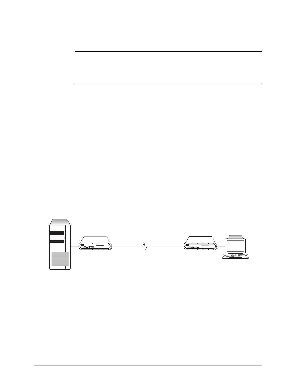
HOST
DTE
The following diagrams illustrate ASM-20 in a variety of applications:
• Point-to-point
• Modem link
• Tail-end for digital networks.
4-WIRE
Up to 23 km
RAD RAD
ASM-20 ASM-20
Figure 1-1. Point-to-point Application
19.2 - 256 kbs
Ter m in a l
Overview 1-1
Page 16
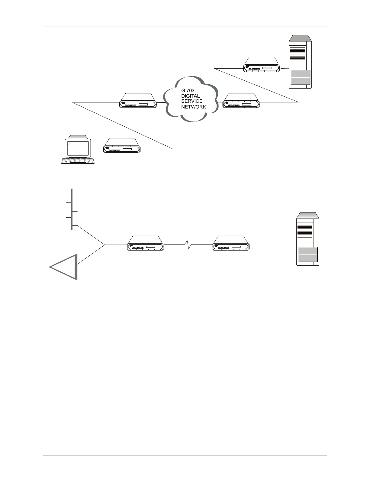
Chapter 1 Introduction ASM-20 Installation and Operation Manual
RAD
ASM-20
RCV CLK
Ter m in a l
RAD
ASM-20
RCV CLK
RAD
ASM-20
EXT CLK
G.703
DIGITAL
SERVICE
NETWORK
RAD
ASM-20
EXT CLK
DTE
Figure 1-2. G.703 Modem Link Application
Features
Options
RAD
ASM-20
RAD
ASM-20
G.703 or
X.21/RS-530/V.24
or V.35 or ETH
DTE
Figure 1-3. Tail-end for Digital Network Application
ASM-20 features V.54 diagnostic capabilities for performing local analog loopback
and local and remote digital loopback. The operator at either end of the line may
test both modems and the line when in digital loopback mode. The loopback is
controlled by either front panel push buttons or via the DTE interface.
The following DTE interface options are available:
• V.24/RS-232(up to 64 kbps)
• V.35
• X.21
• RS-530
• V.36
• G.703 (64 kbps co-directional)
1-2 Overview 02-Aug-2005 10:47
Page 17
ASM-20 Installation and Operation Manual Chapter 1 Introduction
• Built-in Ethernet bridge.
Connection to an RS-449/V.36 interface is accomplished via the RS-530 interface
(see Appendix A, Ethernet Interface). ASM-20 incorporates a built-in Bit Error Rate
Tester (BERT). The internal BERT allows complete testing of both modems and the
line without external test equipment. A front panel switch generates a pseudorandom test pattern (511-bit, according to ITU/V.52) for testing end-to-end
connectivity. The ERROR LED will flash when a bit error is encountered.
1.2 Physical Description
ASM-20 is available as a desk-top unit or a rack-mountable card for a 19" rack.
The rack can carry up to 14 ASM-20 cards which provide a 25-pin
D-type connection to the digital interface. Optional interface adapters for V.35,
X.21, G703 and ETH are available. The ASM-20/R card can detect and indicate
power failure on the remote ASM-20 standalone unit. The RPF LED will light up if
remote power failure occurs.
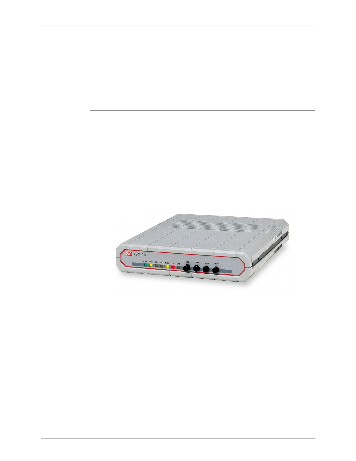
Front Panel
LEDs
Jumpers
Figure 1-4 shows a general view of ASM-20.
Figure 1-4. ASM-20
All controls (push button and LED indicators are located on the ASM-20 front
panel (see Figure 1-4). A description of the front panel can be found in Controls
and Indicators in Chapter 3.
A description of the jumpers can be found in Setting Internal Jumpers and Switches
in Chapter 2. See Table 2-1 and Figure 2-3.
Rear Panel
Figure 1-5. ASM-20 Rear Panel with V.35 Interface
Physical Description 1-3
Page 18
Chapter 1 Introduction ASM-20 Installation and Operation Manual
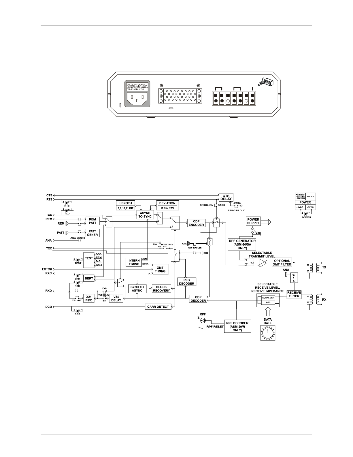
shows an example of an ASM-20 rear panel. A description of the rear panel can
be found in Electrical Installation in Chapter 2.
The line and interface connectors are located on the rear panel of ASM-20 (see
Figure 1-5).
DTE
100-115 VAC
-0.2A T 250V
~230 V/ 0.1A T 250V
GNDRCVXMT
Figure 1-5. ASM-20 Rear Panel with V.35 Interface
1.3 Functional Description
This section contains functional descriptions of the circuit blocks in ASM-20,
primarily those circuits which are required for configuring the modem (see
Figure 1-6).
Figure 1-6. ASM-20 Block Diagram
Encoder
The encoder receives data from the DTE, then modulates the data using the CDD
“conditional diphase modulation” technique.
• 4-wire full-duplex
• 4-wire half-duplex.
1-4 Functional Description 02-Aug-2005 10:47
Page 19

ASM-20 Installation and Operation Manual Chapter 1 Introduction
Modulation Timing
This circuit supplies the transmit clock to the encoder. Three clock sources are
available:
• Internal oscillator
• External from the DTE
• Loop clock derived from the receive signal.
Setting the XMT CLK jumper determines the timing option. See Setting Internal
Jumpers and Switches in Chapter 2 for more information.
XMT Level (optional)
Two options are available for the XMT level (signal level): 0 and -6 dBm. XMT level
is controlled by the XMT LVL jumper. See Setting Internal Jumpers and Switches in
Chapter 2 for more information on the XMT LVL jumper.
An optional output filter to the line is available. This filter can be ordered in
compliance with British Telecom and other PTT requirements.
Receiver
The receiver comprises several circuits as shown in the block diagram
(see Figure 1-6):
• The RECEIVE FILTER removes all the out-band frequencies.
• The AUTOMATIC EQUALIZER comprises several equalizers which are
activated according to baud rate.
• The digital AGC automatically compensates for the attenuation of the line.
Remote Power Failure (RPF)
The Remote Power Failure feature allows the user at a central location to detect a
power failure in a remote modem. The remote power failure feature can only be
configured when the ASM-20/SA standalone unit (remote) operates opposite the
rack-mounted card ASM-20/R (central). When a power failure occurs, ASM-20/SA
transmits a special tone which is detected by ASM-20/R and causes the ERR/RPF
LED to light up. A special push button located on the front panel of ASM-20/R
allows the user to reset the RPF LED. The RPF jumper in the standalone unit
enables or disables the feature. The RPF feature should be disabled for multipoint
applications.
V.54 Diagnostics
V.54 loops are activated either by manual front panel push buttons or via the DTE
interface. The push buttons and the DTE interface can be enabled or disabled
separately by the SWITCH EN, ALB DTE, RLB DTE jumpers respectively. See
Setting Internal Jumpers and Switches in Chapter 2, for more information.
Async to Sync Converter
ASM-20 has an internal asynchronous to synchronous converter and synchronous
to asynchronous converter (used for asynchronous data).
Functional Description 1-5
Page 20

Chapter 1 Introduction ASM-20 Installation and Operation Manual
A synchronous transmission is provided by internal conversion from asynchronous
to synchronous mode in compliance with ITU V.22 bis. In this standard, the
modem compensates for frequency deviation between the modem and the DTE
by adjusting the length of the stop bit of the async character. If the modem’s
frequency is lower than the DTE, the local converter deletes one stop bit in every
four (25%) or eight (12.5%) characters. The remote converter will add a shorter
stop bit (shorter by 12.5% or 25%) before sending the data to the remote DTE.
A suitable operation of the ASYNC to SYNC converter is selected by adjusting the
proper character length and frequency deviation setting (dip switch bank), see
Figure 2-3 and Table 2-2.
X.21 Buffer (for X.21 interface)
To allow tail-end connection on an X-21 interface, a buffer is provided on received
data. When ASM-20 is used in external clock configuration, set jumper JP2 to EXT.
When internal or receive clock configuration is used, set the jumper to the
opposite side. See Appendix C, IR-X.21B Interface Module for more information.
Test Pattern Generator and Receiver
This feature allows for easy and quick testing of the local modem as well as the
communication link. When the PATT button on the front panel is activated, the
circuit sends and checks a standard 511-bit pseudo random pattern. If errors are
encountered, the ERROR LED remains ON or blinks.
The test can be carried out in local analog loopback, in remote digital loopback or
in normal point-to-point operation opposite a remote ASM-20 modem. Press the
PATT push button on the remote unit or connect a Bit Error Rate Tester which uses
the standard 511-bit pattern.
X.21 External Clock Buffer Option
Available with X.21 interface model only. See Appendix C, IR-X.21B Interface
Module for more information.
G.703 DTE Interface
Available with G.703 interface model only. See Appendix B, IR-G.703
Codirectional Interface (64 kbps) for more information.
1-6 Functional Description 02-Aug-2005 10:47
Page 21

ASM-20 Installation and Operation Manual Chapter 1 Introduction
1.4 Technical Specifications
Transmission Line
Digital Interface
Type
Range
Level
Transmit Impedance
Receive Impedance
Return Loss
Carrier
Modulation
Type
Unloaded twisted pair 19 to 26 AWG
See Table 1-1
Strap-selectable to 0 dBm or -6 dBm
150Ω or LOW (strap selectable)
150Ω or HIGH (strap selectable)
Greater than 15 dB
Controlled by RTS or constantly ON
Conditional diphase European Std. D1
V.24/RS-232 via 25-pin D-type, (up to 64 kbps
only), female connector
V.35 via 34-pin female connector
X.21 via 15-pin D-type female connector
RS-530 (RS-422) via 25-pin D-type female
connector
V.36 (RS-449) via 37-pin female connector using
mechanical cable adapter provided with the
product
G.703 Codirectional (64 kbps) via terminal block
or RJ-45
Built-in Ethernet bridge via RJ-45 connector or
BNC
Data Rates - selectable
RTS/CTS Delay
Length of Word
Stop Bits
Sync:
19.2, 32, 48, 56, 64, 72, 96, 112, 128, 144, 192,
256 kbps
Async:
19.2, 28.8, 38.4, 57.6, 115.2 kbps
Switch selectable to:
- 0 ms
- 9 ms
- 70 ms
8, 9, 10, 11
1, 1.5, 2
Technical Specifications 1-7
Page 22

Chapter 1 Introduction ASM-20 Installation and Operation Manual
Diagnostics
(Complies with the
V.54 Standard)
Timing Elements
Indicators
Digital Loopback
Analog Loopback
Pattern
Receive Clock
Transmit Clock
Power
Request to Send
Transmit Data
Receive Data
Local (DIG), activated by a manual switch
Remote (REM), activated by a manual switch or
by a control signal from the DTE interface
connector
Local (ANA), activated by a manual switch or by a
control signal from the DTE interface connector
Test pattern activated by manual switch
Derived from the receive signal
Derived from 3 alternative sources:
Internal oscillator
External from the DTE
Loop clock derived from the receive signal
PWR (green)
RTS (yellow)
TD (yellow)
RD (yellow)
Electrical
Physical
Environment
Data Carrier Detect
Test
Bit errors
Power Supply
ASM-20 Modem
ASM-20-R Card
Temperature
Humidity
DCD (yellow)
TEST (red)
Err (yellow)
115 or 230 V (± 10%)
47 to 63 Hz; 5W
-48 VDC or 24 VDC
Height: 44 mm/ 1.7 in
Width: 215 mm/ 8.5 in
Depth: 243 mm/ 9.6 in
Weight: 1.1 kg / 2.4 lb
Dimensions: Fits ASM-MN-214 modem rack
Weight: 290 gm / 10.1 oz
0° - 50°C / 32° - 122°F
Up to 90%, non-condensing
1-8 Technical Specifications 02-Aug-2005 10:47
Page 23

ASM-20 Installation and Operation Manual Chapter 1 Introduction
Table 0-1 Approximate Range
Baud
Rate
19 AWG
(0.8 mm)
22 AWG
(0.6 mm)
24 AWG
(0.5 mm)
26 AWG
(0.4 mm)
kbps km miles km miles km miles km miles
256 3.75 2.3 2.85 1.75 2.25 1.4 1.9 1.2
192 6.0 3.7 4.5 2.8 3.5 2.2 2.7 1.7
144 10.6 6.6 6.75 4.2 4.5 2.8 3.4 2.1
128 12.4 7.7 7.3 4.5 5.0 3.1 3.6 2.2
115.2* 12.8 7.8 7.65 4.75 5.25 3.3 3.8 2.5
112 12.8 8.0 8.0 5.0 5.5 3.4 4.0 2.5
96 13.0 8.1 8.3 5.15 6.0 3.7 4.15 2.6
72 15.0 9.3 9.4 5.8 6.25 3.9 4.3 2.65
64 17.6 11.0 11.0 6.8 7.5 4.6 5.3 3.3
57.6* 18.8 11.7 11.75 7.3 8.0 5.0 5.6 3.5
56 18.8 11.7 11.75 7.3 8.0 5.0 5.6 3.5
48 19.4 12.0 12.2 7.6 8.25 5.2 5.8 3.6
38.4* 20 12.5 12.5 7.8 8.5 5.3 6.0 3.7
32 20.5 12.75 12.85 8.0 8.75 5.4 6.2 3.85
28.8* 20.5 12.75 12.85 8.0 8.75 5.4 6.2 3.85
19.2** 23.0 14.0 14.0 8.7 9.75 6.0 7.0 4.3
* Async baud rate
** Sync/Async baud rate
Technical Specifications 1-9
Page 24

Chapter 1 Introduction ASM-20 Installation and Operation Manual
1-10 Technical Specifications 02-Aug-2005 10:47
Page 25

Chapter 2 Installation and Setup
2.1 Introduction
This chapter provides instructions for mechanical and electrical installation of the
ASM-20 standalone model.
• For rack installation of the ASM-20, see Chapter 5, Card Cage Version.
• For ETH interface installation see Appendix A, Ethernet Interface.
• For G.703 interface installation, see Appendix B, IR-G.703 Codirectional
Interface (64 kbps).
• For X.21B interface installation, see Appendix C, IR-X.21B Interface Module.
• For V.36 interface installation, see Appendix E, Connection to RS-422.
After installation has been completed, see Chapter 3, Operation for operating
information and system checkout to assure normal operation.
2.2 Site Preparation and Prerequisites
Install ASM-20 within 1.5m (5 ft) of a grounded, easily accessible AC outlet. The
outlet should be capable of furnishing 115 VAC or 230 VAC (depending on rated
voltage of unit).
For DC units, the DC supply must be adequately isolated from the mains supply.
To prevent a fire hazard, the line supply lead should be fused or current limited.
Allow at least 90 cm (36 in) of frontal clearance for operating and maintenance
accessibility. Ensure that there is at least 10 cm (4 in) clearance at the rear of the
unit for signal lines and interface cables.
2.3 Package Contents
The ASM-20 package includes the following items:
• ASM-20
• AC cord
• 48 VDC plug (optional)
• Adapter cable for the different interfaces (optional)
• ASM-20 Installation and Operation Manual.
Package Contents 2-1
Page 26

Chapter 2 Installation and Setup ASM-20 Installation and Operation Manual
2.4 Equipment Needed
ASM-20 is a standalone device designed to be placed on a tabletop or bench. It is
delivered completely assembled. No provisions are made for bolting ASM-20 to
the tabletop.
No special equipment is needed for installing ASM-20.
2.5 Setting Internal Jumpers and Switches
To set the jumpers and switches:
1. Disconnect the power cable.
2. Loosen the screws holding the bottom cover in place.
3. Remove the top cover.
4. Adjust the jumpers as required. See Table 2-1.
5. Replace the top cover and tighten the retaining screws.
2-2 Setting Internal Jumpers and Switches
Page 27

ASM-20 Installation and Operation Manual Chapter 2 Installation and Setup
DIS
CON
CHASS
150
LOW
J13
J10
150
HIGH
RCV IMPRCV LVL
LOW
HIGH
J9
0 dbm
-6 dbm
J12
ON
OFF
RPF. XMT LVL XMT IMP
*
J11
EN
RLB DTE
J7 J8
4
5
3
6
2
1
0
F
7
8
kbps
9
A
E
D
B
C
0 - 256
1 - 192
2 - 144
BAUD RATE
3 - 128
SW3
%
STOP BIT
12
25
8
9
SW2
ONON
ONON
321
LN1 BIT
LN0
11
10
ON
ON
OFF
ON OFF
ON
OFF
J14
DIS
EN
DIS
ALB DTE
4 - 115.2
5 - 112
6 - 96
7 - 72
8 - 64
9 - 57.6
A - 56
B - 48
C - 38.4
D - 32
E - 28.8
F - 19.2
Warning
Note
J6
INT
EXT
RCV
ASY
ON
EN
DIS
V54 DIS
CNTRL
CARRIER
J1 J2 J3
XMT CLK
0970
J4
ON
RTS-CT S
DLY (ms)
OFF
SW. EN.
* J11 - Only for standalone option
Figure 2-1. PCB Layout Diagram
In certain locations where permanent excessive high voltages are present on
the lines, disconnecting the signal ground from the chassis ground may render
the unit unsafe for connection to unprotected telecommunication networks.
For applications using an X.21 interface external clock (DTE timing source), connect
the input clock to Pins 7(a) and 14(b) of the 15-pin connector. In X.21, one of the
modems should be set to RCV clock.
Table 2-1 specifies the strap selection settings. The jumper and switch identity
numbers correspond to PCB Layout Diagram (see Figure 2-1).
Setting Internal Jumpers and Switches 2-3
Page 28

Chapter 2 Installation and Setup ASM-20 Installation and Operation Manual
Table 2-1. ASM-20 Strap Selection Settings
Jumper and
Switch Identity
J1
V54 DIS
J2
CARRIER
J3
XMT CLK
J4
RTS-CTS
DLY (ms)
J6
SW. EN.
J7
RLB DTE
J8
ALB DTE
Function Possible Settings**
Prevents activation of remote V.54 loops. EN
DIS
Selects the transmit carrier mode. When ON, transmit
carrier is constantly ON. When CNTRL, transmit carrier is
ON
CNTRL
ON only when RTS is High. In X.21, RTS is replaced by the
CONTROL signal.
Selects the transmit timing signal from either: internal clock,
external clock or receive clock and enables working in
Asynchronous mode.
INT
EXT
RCV
ASY
Selects the delay between RTS and CTS. 0
9
70
Enables activation of DIG, ANA and REM loopbacks via the
front panel push buttons.
Enables Remote Loopback command from the DTE.
ON
OFF
EN
DIS
Enables Analog Loopback command from the DTE.
EN
DIS
J9
Selects the receiver sensitivity level required.
RCV LVL
J10
Selects receive line impedance.
RCV IMP
J11
Enables the Remote Power Failure feature.
RPF*
J12
Selects the transmit output level to the line.
XMT LVL
J13
Selects the transmit line impedance.
XMT IMP
J14
CHASS
The CON setting connects Signal Ground to Chassis
Ground. The DIS setting disconnects them.
* Only for standalone option
** Factory settings are shown in bold.
LOW
HIGH
150Ω
HIGH
ON
OFF
0 dBm
-6 dBm
150Ω
LOW
DIS
CON
2-4 Setting Internal Jumpers and Switches
Page 29

ASM-20 Installation and Operation Manual Chapter 2 Installation and Setup
Table 2-2. ASM-20 Strap Selection Settings (Cont.)
Jumper and
Function Possible Settings **
Switch Identity
SW2
ASYNC LENGTH
(3 dip switches)
Select character length in async mode
(see Table 2-3. Async Character Length Setting
for further explanation).
Selects the stop bit reduction rate to be used in async
mode.
SW3
Selects the data rate. Rate
Baud Rate (kbps)
$
Async baud rate
$$
Async/Sync baud rate
** Factory settings are shown in bold.
S1 S2 No. Bits
OFF OFF 8
ON OFF 9
OFF ON 10
ON ON 11
S3
OFF 25%
ON 12.5%
0) 256 kbps
1) 192 kbps
2) 144 kbps
3) 128 kbps
4) 115.2 kbps
$
5) 112 kbps
6) 96 kbps
7) 72 kbps
8) 64 kbps
9) 57.6 kbps
$
A) 56 kbps
B) 48 kbps
C) 38.4 kbps
$
D) 32 kbps
E) 28.8 kbps
F) 19.2 kbps
$
$$
Setting Internal Jumpers and Switches 2-5
Page 30

Chapter 2 Installation and Setup ASM-20 Installation and Operation Manual
X
Table 2-3. Async Character Length Setting
Start Bit Data Bits Parity Stop Bit No. of Bits
1 5 NONE 2 8
1 6 NONE 1, 1.5, 2 8
9
1 6 ODD, EVEN 1, 1.5, 2 9
10
1 7 NONE 1, 1.5, 2 9
10
1 7 ODD, EVEN 1, 1.5, 2 10
11
1 8 NONE 1, 1.5, 2 10
11
1 8 ODD, EVEN 1, 1.5, 2 11
2.6 Connecting the Cables
The line and digital interface connectors (located on the rear panel of ASM-20)
consist of a DTE interface connector and a five-screw terminal block. The DTE
interface connector may be 34-pin for V.35 (see Figure 2-2), 15-pin for X.21 (see
Figure 2-3) or 25-pin for RS-530/RS-422 or RS-232/V.24.
The terminal block provides a connection between transmit and receive twisted
pair lines. The transmit and receive pairs are polarity insensitive. The transmit pair
is connected to the terminals marked XMT, the receive pair is connected to the
terminals marked RCV. If the cable is shielded, the shield may be connected to the
terminal marked GND.
CAUTION:
PROTECTION AGAINST RISK OF
FIRE, REPLACE ONLY WITH SAME
TYPE AND RATING OF FUSE.
CAUTION:
PROTECTION AGAINST RIS K OF
FIRE, REPLACE ONLY WITH SAME
TYPE AND RATING OF FUSE.
-1A T 250V
~230 VAC
FOR CONTINUED
Figure 2-2. ASM-20 - V.35 Rear Panel
FOR CONTI NUED
DTE
DTE
X.21
MT RCV GND
Line Con nector
Figure 2-3. ASM-20 - X.21 Rear Panel
2-6 Connecting the Cables
Page 31

Chapter 3 Operation
This chapter:
• Describes the controls and indicators of ASM-20 and their functions
• Explains the operation procedures
• Provides jumper and switch information.
Installation procedures given in Chapter 2, Installation and Setup must be
completed and checked before attempting to operate the ASM-20.
3.1 Power On
Apply AC power by connecting the AC power cord to an acceptable AC source.
The PWR LED should light up, indicating that the ASM-20 is on. If the local and
remote ASM-20 units are in operation and passing data, the following indicator
conditions will exist:
• PWR: On
• RTS: On or Flashing
• TD: Flashing or Off
• RD: Flashing or Off
• DCD: On or Flashing
• TEST: Off.
If you do not obtain the above LED indications following initial power on, check
that the three test push buttons are not depressed.
3.2 Controls and Indicators
All controls (push button switches) and LED indicators are located on the ASM-20
front panel. Their functions are described in Table 3-1 and correspond to the
identification numbers in Figure 3-1 and Figure 3-2.
Controls and Indicators 3-1
Page 32

Chapter 3 Operation ASM-20 Installation and Operation Manual
ASM-20
RTSPWR TD DCD TEST ERR
RD
DIG ANA REM PATT
1 2 3
E
5 6 74
ABC D
Figure 3-1. ASM-20/SA Front Panel
PWR
RTS
TD
DCD
TEST
DIG
ANA
PATT
ERR
RPF
1
2
3
4
5
7
A
B
C
D
ASM - 20
Figure 3-2. ASM-20R Front Panel
3-2 Controls and Indicators
Page 33

ASM-20 Installation and Operation Manual Chapter 3 Operation
Table 3-1. Control and Indicator Functions
Item Name Type Function
A DIG Pushbutton The Digital Loopback switch causes the local ASM-20 to loop
received data and clock back to its transmitter. Data Set Ready
will turn off (see
B ANA Pushbutton The Analog Loopback (V.54 Loop 3) switch causes the local
ASM-20 to loop its transmitter output back to its receiver (see
Figure 4-3
when DTE COMMAND ALB strap is set to EN.
C REM Pushbutton The Remote Digital Loopback (V.54 Loop 2) switch causes the
remote ASM-20 to loop received data and clock to its
transmitter (see
loopback may be also activated from the terminal when DTE
COMMAND RLB strap is set to RLB EN.
D PATT Pushbutton The PATT switch causes the ASM-20 to send and receive a 511
test pattern. If errors are encountered,, the ERROR LED is ON
or blinks. Receive Data and Clear to Send will turn off.
Note: The CARRIER jumper should be set to ON; if set to
CNTRL, the RTS signal must be high.
Figure 4-5).
). This loopback may also be activated from the DTE
Figure 4-4). Data Set Ready will turn off. This
E RPF RESET Pushbutton Resets ERR/RPF LED (only available in ASM-20/R).
1 PWR LED Indicator Green LED is on when power is on.
2 RTS LED Indicator
ITU 105
3 TD LED Indicator
ITU 103
4 RD LED Indicator
ITU 104
5 DCD LED Indicator
ITU 109
6 TEST LED Indicator
ITU 142
7 ERR/RPF LED Indicator ERR: Yellow LED goes ON momentarily when PATT switch is
Yellow LED is on when terminal activates Request to Send.
Yellow LED is on when steady SPACE is being transmitted. It
flickers when data is transmitted.
Yellow LED is on when steady SPACE is being received.
It flickers when data is received.
Yellow LED is on when a valid receive signal is present.
Red LED is on when the ASM-20 is in any of the three loopback
modes or PATT mode.
activated and then goes out. If there are errors in the test
pattern, the LED blinks or remains ON.
RPF: Indicates power failure in remote standalone units
(ASM-20/R only). Reset by depressing RPF reset push button.
Controls and Indicators 3-3
Page 34

Chapter 3 Operation ASM-20 Installation and Operation Manual
3.3 Operation
ASM-20 operates entirely unattended, except when the occasional monitoring of
LED indicators is required.
Test Activation
In order to verify that the ASM-20 is operating correctly, use the internal BERT and
analog loopback tests as described in Bit Error Rate Tester (BERT) in Chapter 4 and
Local Test - Analog Loopback in Chapter 4.
Operational Jumper and Switch Changes
If you need to reconfigure the ASM-20 for a different type of operation, the
jumpers and switches must be changed to correspond to the new operating mode.
Only authorized or qualified personnel should have access inside the
equipment. Disconnect the ASM-20 power cable before opening the top cover.
Warning
For guidance in repositioning the jumpers and switches, see Setting Jumpers and
Switches in Chapter 2. The equipment will become unsafe for connection to
telecommunication networks in some locations, if the signal ground is
disconnected from the chassis ground.
3.4 Power Off
To turn off an AC powered ASM-20:
Remove the AC power cord from the AC source.
To turn off a DC powered ASM-20:
Turn off the circuit breaker that supplies the DC mains.
3-4 Power Off
Page 35

Chapter 4
Troubleshooting and
Diagnostics
This chapter contains procedures for performing system diagnostic tests for
ASM-20. Use the test procedures provided in this chapter to:
• Verify normal system operation
• Isolate faulty equipment in the event of failure.
Tests are activated by control push buttons on the ASM-20 front panel and
monitored via LED indicators. For a description of the ASM-20 controls and
indicators and their functions, see Chapter 3, Operation.
4.1 Loop Test Procedure
The test switches and LED indicators built into ASM-20 allow rapid checking of the
data terminals, ASM-20 and lines. Use the test procedures provided in this chapter
to check normal system operation and isolate faulty equipment in the event of
failure. Each test verifies the operational performance of a unit in the system or
provides a positive indication of equipment failure.
Before testing operation of the data system equipment and line circuits, ensure
that all units are turned on and correctly configured.
4.2 Bit Error Rate Tester (BERT)
The Bit Error Rate Tester (BERT) can be activated in any diagnostics test in which
the test pattern transmitted is looped back to the BERT for comparison (see
Figure 4-1).
Bit Error Rate Tester (BERT) 4-1
Page 36

Chapter 4 Troubleshooting and Diagnostics ASM-20 Installation and Operation Manual
T
PATT
Pressed
Pattern
Generator
Pattern
Tes t er
Error
ASM-20
XMT
RCV
Figure 4-1. BERT Using Loops
Alternatively, the complete link can be tested when using two ASM-20 modems or
an external BERT. Figure 4-2 illustrates the two options for testing a complete link:
• Press the PATT push button of the local modem and check the ERR/RPF LED.
At the remote side check an external BERT.
• Press the PATT push button of the local and remote modems and check their
ERR LEDs.
PATT
Pressed
PAT
Pressed
Error
Pattern
Generator
Pattern
Te st e r
LOCAL ASM-20
Pattern
Tes t er
Error
Pattern
Generator
REMOTE ASM-20
Figure 4-2. Two BERTs Operating End-to-End
RCV
511
External
BERT
XMT
4-2 Bit Error Rate Tester (BERT)
Page 37

ASM-20 Installation and Operation Manual Chapter 4 Troubleshooting and Diagnostics
4.3 Modem Self Test
The modem self test verifies that ASM-20 is operating correctly.
To verify that ASM-20 is operating correctly:
1. Press the ANA (Analog Loopback) push button on the front panel. Both the
TEST and DCD LEDs should light up. If the DCD LED does not light up, check
that the CARRIER jumper is ON or that the RTS signal is ON (high).
2. Press the PATT push button. Verify that:
DCD LED is still lit up
TEST LED is still lit up
ERR LED lights up for a short period.
The ERR LED should then turn off. If it lights up or blinks, then ASM-20 is
faulty and should be replaced. If the test executes correctly, restore all the
push buttons and jumpers to the required position.
4.4 Local Test - Analog Loopback
This test checks the performance of the local modem, the local data terminal and
the cables connecting them. Perform it separately at the local and remote sites.
ANA
Pressed
CLK
DATA
TERMINAL
CLK
DATA
XMTR
RCVR
ASM-20
Figure 4-3. Local ASM-20 in Analog Loopback
LINE
To check the performance of the local modem and the local data terminal:
1. Press the ANA (Analog Loopback) push button on the front panel (see
Figure 3-1). This test can also be activated via the pin on the DTE interface.
See Table 2-2 for more information. The TEST LED should turn on. ASM-20
transmit output is now connected to its own receiver (see Figure 4-3).
Local Test - Analog Loopback 4-3
Page 38

Chapter 4 Troubleshooting and Diagnostics ASM-20 Installation and Operation Manual
2. Check that the DTE is operating properly and can be used for a test. If a fault is
indicated, call a technician or replace the unit.
3. Execute the test using one of the methods described below:
Use the DTE and check the echoed data stream
Use an external Bit Error Rate Tester (BERT) unit
Use the internal Bit Error Rate Tester (BERT). Press the PATT push button.
The ERR LED will light up briefly to indicate that the LED is functioning. If
any bit error is encountered, the LED will blink or remain ON.
4. Perform Step 3 at both ends. If the BERT test equipment does not indicate a fault, but the data terminal does, follow the manufacturer’s test procedures for the data terminal and check that the cable connecting the terminal and ASM-20 is working. After completion of the test (or when the fault has been corrected), restore the ANA push button to the OFF position by pressing the ANA push button again. Proceed to Communication Link Tests below.
4.5 Communication Link Tests
Remote Digital Loopback
This test determines the performance of the local and remote ASM-20, and the
lines connecting them.
To check the performance of the local and remote ASM-20:
1. Press the REM (Remote Loopback) push button, providing a loopback at the
remote ASM-20 (see Figure 4-4). (This test can also be activated via the pin on
the DTE interface.) The TEST LED should light up at both the local and remote
units.
2. Perform the BERT test using one of the methods described below:
Use the DTE and check the echoed data stream
Use an external Bit Error Rate Tester (BERT) unit
Use the internal Bit Error Rate Tester (BERT). Press the PATT push button.
The ERR LED will light up briefly to indicate that the LED is functioning. If
any bit error is encountered the LED will blink or remain ON.
3. If Step 2 indicates a fault, and if the modem test described Modem Self Test on
page 4-3 was positive for both the local and remote modems, the line circuits
are not operating properly.
4-4 Communication Link Tests
Page 39

ASM-20 Installation and Operation Manual Chapter 4 Troubleshooting and Diagnostics
G
REM
Pressed
LOCAL
DATA
TERMINAL
Local Digital Loopback
This test is activated by pressing the DIG push button. It loops the received data
back to the remote ASM-20. (This test is equivalent to activating the remote
loopback from the remote ASM-20 – see Figure 4-5). The operator at the remote
end can determine the performance of the local and remote ASM-20 units, and
the lines between them.
Note
The modem with the pressed DIG push button must be in RCV or ASY mode
DATA
CLK
CLK
DATA
XMTR
RCVR
LOCAL ASM-20
REMOTE ASM-20
Figure 4-4. Remote ASM-20 in Digital Loopback
RCVR
REMOTE
DATA
TERMINAL
XMTR
DI
Pressed
REMOTE
DATA
TERMINAL
DATA
CLK
DATA
CLK
XMTR
RCVR
REMOTE ASM-2 0
LOCAL ASM-20
Figure 4-5. Local ASM-20 in Digital Loopback
RCVR
LOCAL
DATA
TERMINAL
XMTR
Communication Link Tests 4-5
Page 40

Chapter 4 Troubleshooting and Diagnostics ASM-20 Installation and Operation Manual
4.6 Frequently Asked Questions
Q. How is the new version of ASM-20 different from the older version?
A. ASM-20 has been improved in order to get CE mark approval and has some
new features. A different ordering name, ASM-20-2, was given to the newer
version. Presently, any order received for ASM-20 or ASM-20-2 will be delivered
as ordered until the stock of existing ASM-20 products is depleted. After the stock
is depleted, orders for any version will be delivered with the new ASM-20-2
boards only.
The following table describe the differences between the old ASM-20 and the new
version.
Table 4-1. Differences in Versions
ASM-20 ASM-20-2
Non-modular interfaces (V.24,
X.21 etc.); part of the main board
Two ordering options for
synchronous rates:
32 kbps - 128 kbps
32 kbps - 144 kbps
No Ethernet support Ethernet built-in bridge
Metal box Plastic box
Terminal block with screws Clip terminal block
Main chip RJ008 and external
BERT chip
No CE mark CE mark
No asynchronous transmission Asynchronous transmission
Modular interfaces
All synchronous rates from
19.2 kbps - 256 kbps.
Main chip RJ016 which includes
BERT chip
capability
The above versions are compatible with each other within similar synchronous
rates.
Additionally, the ASM-20-2 has been improved in order to get a better line surge
protection. In many cases line surges are caused by lightening strikes. The
improved line protection of ASM-20-2 complies with the ITU-T/K.21 standard.
The line interface has been modified by adding two Gas surge protection diodes
and another two Transorber surge protection diodes. The Gas diodes protect
against line surges above 300V and the Transorber diodes protect against surges
below 300V.
4-6 Frequently Asked Questions
Page 41

ASM-20 Installation and Operation Manual Chapter 4 Troubleshooting and Diagnostics
4.7 Technical Support
Technical support for this product can be obtained from the local distributor from
whom it was purchased.
For further information, please contact the RAD distributor nearest you or one of
RAD's offices worldwide. This information can be found at www.rad.com
About RAD > Worldwide Offices; distributors – Where to Buy > End Users).
(offices –
Technical Support 4-7
Page 42

Chapter 4 Troubleshooting and Diagnostics ASM-20 Installation and Operation Manual
4-8 Technical Support
Page 43

Chapter 5 Card-Cage Version
This chapter describes the ASM-20/R card version, designed for installation in the
ASM-MN-214 card cage. The chapter describes:
• ASM-MN-214 card cage
• ASM-20/R card version
• ASM-20/R power supply
• How to install ASM-20/R.
5.1 ASM-MN-214 Card Cage
The ASM-MN-214 card cage contains one or two power supplies and up to 14
plug-in cards. The card types can be ASM-20/R or other RAD rack version
modems/converters - any combination of up to 14 plug-in cards.
For each of the 14 cards, the rear panel (see Figure 5-1) contains a male connector
for the terminal block and a DB-25 connector. A protection cover protects the
terminal block connectors.
The terminal block (see Figure 5-1) is to be attached to the rear panel terminal
block connectors. It contains screws for connecting the transmit and receive pairs
and ground, if present.
The 25-pin D-type female interface connector provides all interface signals for the
digital interfaces. Modems with X.21 or V.35 interface require an external
mechanical adapter. Two optional interface attachments, CIA/V.35/1 and
CIA/X.21, can be ordered separately from RAD. CIA/X.21 converts two adjacent
DB-25 connectors to two X.21 15-pin connectors. CIA/V.35/1 converts one DB-25
connector to a V.35 34-pin connector. V.36 modem cards are supplied with a
RAD adapter cable CBL 530/449F, which converts the DB-25 connector to a V.36
37-pin connector. The adapter cable and two interface attachments are also
shown in Figure 5-1.
ASM-MN-214 Card Cage 5-1
Page 44

Chapter 5 Card-Cage Version ASM-20 Installation and Operation Manual
Figure 5-1. ASM-MN-214 Rear Panel
5-2 ASM-MN-214 Card Cage
Page 45

ASM-20 Installation and Operation Manual Chapter 5 Card-Cage Version
5.2 ASM-20/R Card Version
Figure 5-2. ASM-20/R Front Panel
shows the ASM-20/R card front panel. The LEDs and switches of the card version
are identical in their functionality to those of the standalone device. For this
information, see Controls and Indicators, in Chapter 3.
PWR
RTS
TD
RD
DCD
TEST
ERR
RPF
DIG
ANA
REM
PATT
ASM - 20
Figure 5-2. ASM-20/R Front Panel
ASM-20/R Card Version 5-3
Page 46

Chapter 5 Card-Cage Version ASM-20 Installation and Operation Manual
5.3 Power Supply
Power is supplied to the ASM-20/R card from the ASM-MN-214 power supply via
the chassis. Each ASM-20/R card has two fuses, which protect the entire system
against power failure resulting from a short circuit in one card.
The ASM-MN-214 card cage can accept both AC or DC power supplies. LED
indicators located on the ASM-MN-214 front panel (see Figure 5-3) show activity
when the power supply is connected to the mains plug. The power supply
supports the full card cage with any combination of cards.
AC Supply (100, 115 or 230 VAC)
The AC power supply of the ASM-MN-214 is 100, 115 or 230 VAC, ±10%,
47 to 63 Hz.
DC Supply (-48 VDC)
The DC power supply is -36 to -72 VDC. It uses a DC/DC converter module to
provide the power required for the cards.
Power Supply with Redundancy
This special ordering option is equipped with two separate power supplies,
operating together and sharing the load of the whole card cage. If either of the
power supplies fails, the other one will continue to supply power to the full card
cage.
Two LED indicators show activity of each power supply. They both light when
mains power is provided.
Note
It is possible to combine AC and DC power supplies in the same cage.
5-4 Power Supply
Page 47

ASM-20 Installation and Operation Manual Chapter 5 Card-Cage Version
Figure 5-3. ASM-MN-214 Front Panel
Installation 5-5
Page 48

Chapter 5 Card-Cage Version ASM-20 Installation and Operation Manual
5.4 Installation
To install the ASM-20/R card in the ASM-MN-214 card cage:
1. Install the ASM-MN-214 card cage in the 19" rack.
2. Adjust the jumpers and switches on the card as required (see Table 2-1 and
Figure 2-3 in Chapter 2).
3. Insert the ASM-20/R card into one of the ASM-MN-214 slots. Push the bottom
of the card into the cage to until it is fully inserted into the edge connector
inside the rack. Tighten the screws on the top and on the bottom of each card.
4. Remove the protection cover from the terminal block connectors.
5. Connect the terminal block to the ASM-MN-214 terminal block connector.
6. Connect the line to the terminal block as follows: connect transmit pair to the
terminals marked XMT, the receive pair to the terminals marked RCV, and the
fifth screw to ground (optional).
7. If required, attach the appropriate CIA (CIA/X.21 or CIA/V.35/1) or V.36
adapter cable to the DB-25 connector on the card cage rear panel.
8. Connect the DTE cable to the DB-25 connector, other side of CIA or adapter
cable (depending on your version of the card interface).
9. Connect power to the ASM-MN-214 card cage:
To connect AC power, connect the power cable to the mains supply.
To connect DC power, refer to DC Power Supply Connection Supplement.
5-6 Installation
Page 49

Appendix A Ethernet Interface
This appendix:
• Describes the IR-ETH for RAD modems
• Describes the different IR-ETH connector options
• Lists the Ethernet bridge specifications
• Explains how to install and operate an Ethernet bridge.
A.1 Description
The IR-ETH is an interface module for RAD modems, used for converting the
Ethernet (10BaseT or 10Base2) electrical levels to the modem TTL levels. It also
converts the Ethernet protocol to HDLC to enable long distance transmission and
avoid the Ethernet collision limitation.
The IR-ETH includes an internal, self-learning Ethernet bridge, which enables a
high performance link between two Ethernet segments at a low transmission rate.
The low-speed HDLC transmission is sent over the link using the modem
modulation technique. It is converted back to an Ethernet signal at the remote
modem.
Figure A-1 shows a typical application using an Ethernet interface bridge. Each
modem is connected to an Ethernet network via the Ethernet Interface bridge.
LINK
MODEM MODEM
Figure A-1 Ethernet Interface Typical Application
A.2 IR-ETH Connector Options
Figure A-2 and Figure A-3 show the rear panel of ASM-20 with the IR-ETH
connector options. The IR-ETH connector for the ASM-20/R card (rack mount
version) is shown in Figure A-4.
IR-ETH Connector Options A-1
Page 50

Appendix A Ethernet Interface ASM-20 Installation and Operation Manual
Line Connector
Figure A-2 ASM-20 Rear Panel with IR-ETH/UTP Connector Option
Line Connector
Figure A-3 ASM-20 Rear Panel with IR-ETH/BNC Connector Option
13
12
(13) RCV(+)
(12) RCV(-)
(11) XMT(+)
(9) XMT(-)
(7) GND
11
9
7
DB-25
Figure A-4 IR-ETH Connector for the ASM-20 Rack-Mount Version
When using the RJ-45 connector, the customer must prepare a mechanical cable
for adapting the DB-25 pinout to that of RJ-45. The pinouts of the DB-25 and
RJ-45 connectors are given in Table A-1.
Table A-1 DB-25 and RJ-45 Pin Assignment for IR-ETH Connection
Signal Pin
DB-25 RJ-45
RCV (+) 13 3
RCV (-) 12 6
XMT (+) 11 1
XMT (-) 9 2
GND 7 -
A-2 IR-ETH Connector Options
Page 51

ASM-20 Installation and Operation Manual Appendix A Ethernet Interface
A.3 Ethernet Bridge Specifications
General
LAN
WAN
LAN Table
Filtering and
10,000 addresses
15,000 pps
Forwarding
Buffer
Delay
Standard
Data Rate
Connectors
256 frames
1 frame
Conforms to IEEE 802.3/Ethernet
10 Mbps (20 Mbps 10BaseT FDX)
10BaseT (UTP): Shielded RJ-45
10Base2: BNC connector
Protocol
Data Rate
HDLC
According to the modem transmission rate
A.4 Installation and Operation
Figure A-5 and Figure A-6 show the Ethernet bridge layout, the locations of the DIP
switches, and the rear panel components for the UTP and the BNC versions,
respectively.
4
3
2
1
Figure A-5 Ethernet Bridge Layout (UTP Option)
Installation and Operation A-3
Page 52

Appendix A Ethernet Interface ASM-20 Installation and Operation Manual
4
3
2
1
Figure A-6 Ethernet Bridge Layout (BNC option)
LAN Installation
For 10BaseT installation, either a straight cable or a cross-cable may be required.
Use a cross-cable when connecting to a port that does not implement the
crossover function internally. Otherwise, use a straight cable. (Hubs usually
implement the crossover function internally while NICs and other devices do not.)
Switch Settings
Set switches according to Table A-2.
Switch
Number
1 SQ/FD ON: Ethernet full-duplex mode
2 CMP ON: Strips padding bits inserted in 64-byte frame
3 FIL ON: Passes only frames destined for another LAN
4
* Default settings are shown in bold.
Note
The SQ/FD switch is not used in the Ethernet bridge with the BNC connector
option.
Table A-2 DIP Switches Settings
Name Description*
OFF: Ethernet half-duplex mode
OFF: Transmits frames over WAN as is
OFF: Disables LAN filter; passes all frames transparently
(nc)
LED Indicators
Table A-3 lists the IR-ETH LED indicators and describes their functions.
A-4 Installation and Operation
Page 53

ASM-20 Installation and Operation Manual Appendix A Ethernet Interface
Table A-3 IR-ETH Bridge LED Indicators
LED
Description Location Color
Name
LINK ON indicates good link integrity (available only
Panel Green
in the 10BaseT version)
COLL ON indicates collision on the attached Ethernet
Panel Yellow
segment
RX ON when data is received from the Ethernet
Panel Yellow
attached segment
TX ON when data is transmitted from the modem
Panel Yellow
to the Ethernet segment
ERR D4 Bridge buffer overrun On board Red
Installation and Operation A-5
Page 54

Appendix A Ethernet Interface ASM-20 Installation and Operation Manual
A-6 Installation and Operation
Page 55

Appendix B
IR-G.703 Codirectional
Interface (64 kbps)
B.1 Introduction
This appendix:
• Provides a general description of the IR-G.703 codirectional interface
(64 kbps)
• Describes the EXT mode
• Describes the INT/RCV mode
B.2 General Description
Note
The IR-G.703 is an interface module for RAD modems, converting G.703
codirectional signals to TTL levels. The converted data is sent over the modem link
using the modem modulation technique and converted back at the other end into
G.703 64 kbps codirectional signals, or into any other digital interface signal
possible. The module is available in the following two versions:
• The Standalone version fits into a standalone modem and is available with
two types of physical connections: a terminal block or an RJ-45.
• The Rack version is mounted on the rack version modem card and uses the
modem edge connector for communication. The edge connector is wired, on
the motherboard of the card cage, to the DB-25 connector on the back plane
of the ASM-MN-214 card cage. Figure B-1 illustrates the pinout of the
different connectors.
Byte sync is not kept end-to-end. A violation bit that is inserted every 8 bits does
not appear in the same location at the remote side.
General Description B-1
Page 56

Appendix B IR-G.703 Codirectional Interface (64 kbps) ASM-20 Installation and Operation Manual
Figure B-1. IR-G.703 Connector Options
Note
In Figure B-1, RCV refers to the input signals to the IR module; XMT refers to the
output signals from the module.
The IR-G.703 interface module is shown in Figure B-2. It has two operation modes which are selectable on the PCB board. The selection is made by means of the JP1 jumper located within the module as shown in Figure B-2. The EXT mode is described in EXT Mode on page B-2 and illustrated by Figure B-3. The INT/RCV mode is described in INT/RCV Mode on page B-3 and illustrated by Figure B-4.
Note
On a modem with the IR-G.703 module, set jumper J1 (XMT CLK) to the EXT
position for all clock modes (including INT and RCV.)
TERMINAL BLOCK
OR RJ-4 5
(STANDALONE VERSION)
B.3 EXT Mode
This mode is used in applications, where the system timing is provided by the
G.703 network. The IR-G.703 module has an internal buffer to compensate for the
phase delay introduced to the system by the line delay between the two modems.
The buffer is an 8-bit FIFO connected as shown in Figure B-3.
INT/RCV
JP1
EXT
Figure B-2. Location of JP1 on the IR-G.703 Interface Module
This mode corresponds to the modem clock working in the EXT mode.
B-2 EXT Mode
Page 57

ASM-20 Installation and Operation Manual Appendix B IR-G.703 Codirectional Interface (64 kbps)
A
Modem A Modem B
IR-G.703 Module
G.703
Codirectional
64 kbps network
Timing Source
TX Data
RX Data
Clock
Out
Clock
Recovery
Data
CLK
FIFO
Data
Clock
Recovery
FIFO
EXT Clock Mode RCV Clock Mode
Clock In
TX
RX
RX
Clock
Recovery
TX
Figure B-3. IR-G.703 EXT Mode Timing Block
INT or RCV
Clock Mode
B.4 INT/RCV Mode
This mode is used in applications where the G.703 codirectional 64 kbps
equipment connected to the modem recovers the clock signal from the modem
link. This mode is used mainly when the attached equipment has a G.703
codirectional interface, but is not able to produce clock signals. The module has a
8-bit FIFO buffer to compensate for the phase delay introduced by the G.703
device. Figure B-4 illustrates the buffer connection and the required application
setup.
This mode corresponds to the modem clock working in the INT or RCV mode.
DTE
side
(Depending on the
attached network)
Modem
EXT, INT or RCV
Clock Mode
TX
RX
LINK
side
RX
Clock
Out
TX
Clock
Recovery
FIFO
Modem B
Clock In
IR-G.703 Module
Data
CLK
FIFO
Data
Clock
Recovery
G.703
side
RX Data
TX Data
Equipment
with G.703
interface
INT/RCV Clock Mode
Figure B-4. IR-G.703 INT/RCV Mode Timing Block
INT/RCV Mode B-3
Page 58

Appendix B IR-G.703 Codirectional Interface (64 kbps) ASM-20 Installation and Operation Manual
B-4 INT/RCV Mode
Page 59

Appendix C
X
IR-X.21B Interface Module
This appendix:
• Provides a general description of the IR-X.21B interface module
• Describes the IR-X.21B connectors and pin assignments
• Describes the IR-X.21B interface module
• Describes the EXT mode for the IR-X.21B
• Describes the INT/RCV mode for the IR-X.21B.
C.1 Description
The IR-X.21B is an interface module for RAD modems, converting X.21 signals to
TTL levels. The converted data is sent over the modem link, using the modem
modulation technique, and is converted back at the other end into X.21 signals, or
into any other digital interface signal.
X.21
Network
Figure C-1 shows a typical application of the ASM-20 standalone modem with the
IR-X.21B interface module.
Central Location
Line
Remote Location
X.21
DTE
Figure C-1 Typical ASM-20 X.21 Application
C.2 IR-X.21B Connectors
Figure C-2 shows the rear panel of a standalone ASM-20 with the IR-X.21B
interface module.
CAUTION :
FOR CONTINUED
PROTECTION AGAINST RISK OF
FIRE, REPLACE ONLY WITH SAME
TYPE AND RATING OF FUSE.
DTE
21
Line Connector
Figure C-2 ASM-20 Rear Panel with X.21 Connector
IR-X.21B Connectors C-1
Page 60

Appendix C IR-X.21B Interface Module ASM-20 Installation and Operation Manual
The ASM-20 modem rack version requires an additional adapter to connect
between the DB-15 connector of the X.21 equipment to the DB-25 connector of
the ASM-MN-214 modem rack. For this purpose, an optional DB-15 attachment
CIA/X.21 can be ordered separately from RAD. The attachment connects to the
ASM-MN-214 rear panel as shown in Figure 5-3 for the CIA/V.35 attachment.
Pin Assignment
Table C-1 shows the X.21 DB-15 pin assignment.
Table C-1 IR-X.21B DB-15 (RS-422) Connector Pin Assignment
Pin ID Function
1 Shield Chassis connection
2 A Transmit signal A
3 A Control A
4 A Receive A
5 A Indication A
6 A Signal timing A
7 A External Timing
8 GND Common
9 B Transmit B
10 B Control B
11 B Receive B
12 B Indication B
13 B Signal Timing B
14 B External Timing
C.3 IR-X.21B Interface Module
The IR-X.21B interface module is shown in Figure C-3. It has two operation modes
which are selectable on the PCB board. The selection is made by means of the JP2
jumper located within the module as shown in the figure. The EXT mode is
described on page C-3 and illustrated in Figure C-4. The INT/RCV mode is
described on page C-4 and illustrated in Figure C-5.
Note
The X.21 interface should be in accordance with the modem clock mode. For
example, if the modem is in the EXT mode, then JP2 should be set to the EXT
position.
C-2 IR-X.21B Interface Module
Page 61

ASM-20 Installation and Operation Manual Appendix C IR-X.21B Interface Module
INT/RCV
JP 2
INT/RCV
EXT
clock setting
EXT
clock setting
Connector DB-15
Figure C-3 Location of Jumper JP2 in the IR-X.21B Interface Module
C.4 EXT Mode
This mode is used in applications of X.21 networks where the system timing is
provided by the X.21 network. The IR-X.21B module has internal buffers to
compensate for the phase delay introduced to the system by the line delay
between the two modems. The buffers are 16-bit FIFO’s connected as shown in
Figure C-4. When the modem’s clock mode is EXT, the JP2 jumper must be set to
EXT (see Figure C-3).
EXT Mode C-3
Page 62

Appendix C IR-X.21B Interface Module ASM-20 Installation and Operation Manual
MODEM (EXT)
IR-X.21
TD
FIFO
TC
RD
RC
Buffer
FIFO
Buffer
Transmit Data
External timing from DTE
Receive Data to DTE
Signal Timing
DB
Connector
Figure C-4 EXT Mode Timing Block
from DTE
(2,9)
(7,14)
(4,11)
(6,13)
C.5 INT/RCV Mode
This mode is used in applications where the IR-X.21B side uses the clock signal
from the modem link. This mode is used mainly when the attached equipment has
an IR-X.21 interface, but no ability to produce clock signals. The module has two
16-bit FIFO’s buffers to compensate for the phase delay introduced by the X.21
device.
Figure C-5 illustrates the buffers connection and the required application setup.
When the modem’s clock mode is INT or RCV, the JP2 jumper must be set to
INT/RCV (see Figure C-3).
MODEM (INT or RCV)
IR-X.21
TD
FIFO
TC
RD
RC
Buffer
FIFO
Buffer
Transmit Data
Receive Data to DTE
Signal Timing
DB
Connector
Figure C-5 INT/RCV Mode Timing Block
from DTE
(2,9)
(4,11)
(6,13)
C-4 INT/RCV Mode
Page 63

Appendix D DTE Interface Connectors
Table D-1 lists detailed information about each DTE interface connector.
D-1
Page 64

Chassis ground. May be isolated from
Signal Ground. See Table 2-1.
Description
DB-15 Standalone
Pin Circuit
[Function]
DB-25
Frame
Common Signal and DC power supply
[SHIELD]
ground.
Serial digital data from DTE. The data
[GND]
2 T(A)
2
transitions must occur on the rising
edge of the transmit clock.
Serial digital data at the output of the
modem receiver. The data transitions
9 T(B)
[TRANSMIT]
4 R(A)
11 R(B)
14
3
16
A positive level to the ASM-20 when
clock.
data transmission is desired.
3 C(A)
10 C(B)
4
19
occur on the rising edge of the receive
[RECEIVE]
delay, after receipt of Request to Send,
and when the ASM-20 is ready to
transmit.
[CONTROL]
A positive level from the ASM-20 with
the power is on, and the ASM-20 is
(a)not in the DIGITAL LOOP mode, or
(b) has not received a REMOTE
LOOPBACK signal from the remote
unit.
A positive level from the ASM-20 when
Not used.
Table D-1. Interface Signal List (Female Connectors) Pinout and Standard Signal Names
RS-232 V.35 EIA-530 X.21
DB-25 Standalone
and Frame
Pin Circuit
34-pin
Standalone
Pin Circuit
DB-25
Frame
Standalone
and Frame
7 AB 7 8 -
2 BA(A)
14 BA(B)
Ground
S TD(B) 103
P TD(A) 103
9
3 BB(A)
16 BB(B)
R RD(A) 104
T RD(B) 104
13
19 CA(B)
13 CB(B)
22 CC(B)
23 CD(B)
Appendix D DTE Interface Connectors ASM-20 Installation and Operation Manual
Signal Function DB-25
Protective Ground 1 1 A Frame 101 1 1 1 -
Signal Ground 7 7 B Signal 102
Transmitted Data 2 11
Received Data 3 12
Request to Send 4 4 C RTS 105 4 CA(A)
Clear to Send 5 5 D CTS 106 5 CB(A)
Data Set Ready 6 6 E DSR 107 6 CC(A)
Data Terminal Ready 20 20 H DTR 108 20 CD(A)
D-2
Page 65

A positive level from the ASM-20,
except when a loss of the received
Description
DB-15 Standalone
Pin Circuit
[Function]
DB-25
Frame
signal is detected, or when Data Set
5 I(A)
12 I(B)
[INDICATION]
8
10
Ready is negative.
A serial data rate clock input from the
data source. Positive clock transitions
must correspond to data transitions.
7 (A)
14 (B)
24
11
A transmit data rate clock for use by an
external data source. Positive clock
transitions correspond to data
transitions.
6 S(A)
13 S(B)
[SIGNAL TIMING]
15
12
commands the ASM-20 into Local
Analog Loopback (V.54 Loop 3). See
external data sink. Positive clock
transitions correspond to data
transitions.
A receive data clock output for use by
Table 2-2.
commands the ASM-20 to send a
remote Loopback command (V.54
Loop 2) to the remote ASM-20. See
ASM-20; positive during any test mode.
Table 2-2.
Table D-1. Interface Signal List (Female Connectors) Pinout and Standard Signal Names (Cont.)
RS-232 V.35 EIA-530 X.21
Pin Circuit
Pin Circuit
and Frame
10 CF(B)
DB-25 Standalone
and Frame
34-pin
Standalone
DB-25
Frame
Standalone
24 DA(A)
11 DA(B)
15 DB(A)
12 DB(B)
U SCTE(A) 113
W SCTE(B) 113
Y SCT(A) 114
A SCT(B) 114
16
24 19
10
17 DD(A)
9 DD(B)
X SCR(B) 115
V SCR(A) 115
23
ASM-20 Installation and Operation Manual Appendix D DTE Interface Connectors
Signal Function DB-25
Carrier Detect 8 8 F DCD 109 8 CF(A)
External Transmit
Clock
Transmit Clock 15 14
Receive Clock 17 22
Local Analog Loop 18 18 L and j 141 18 LL A control signal input; when on,
Remote Loopback 21 21 N and h 140 21 RL A control signal input; when on,
Test Indicator 25 25 n and k 142 25 TM A control signal output from the
D-3
Page 66

Appendix D DTE Interface Connectors ASM-20 Installation and Operation Manual
D-4
Page 67

Appendix E Connection to RS-422
Table E-1 describes how to connect ASM-20 (EIA 530) to a RS-422 (V.36) DTE.
Table E-1. Interface List for Connecting ASM-20 (RS- 530) to RS-422 (V.36) DTE
Signal Function RS-449 (RS-422/423)
37 Pins
Pin Circuit Pin Circuit
Protective Ground 1 Shield 1
Signal Ground 19 SG 7 AB
DTE Common Return 37 SC
DCE Common Return 20 RC
Transmitted Data 4 SD (A)
22 SD (B)
Received Data 6 RD (A)
24 RD (B)
Request to Send 7 RS (A)
25 RS (B)
Clear to Send 9 CS (A)
27 CS (B)
Data Set Ready 11 DM (A)
29 DM (B)
Data Terminal Ready 12 TR (A)
30 TR (B)
EIA 530
DB-25 Female Standalone and Frame
2 BA (A)
14 BA (B)
3 BB (A)
16 BB (B)
4 CA (A)
19 CA (B)
5 CB (A)
13 CB (B)
6 CC (A)
22 CC (B)
20 CD (A)
23 CD (A)
Carrier Detect 13 RR (A)
31 RR (B)
External Transmit Clock 17 TT (A)
35 TT (B)
Transmit Clock 5 ST (A)
23 ST (B)
Receive Clock 8 RT (A)
26 RT (B)
Local Analog Loopback 10 LL 18 LL
Remote Loopback 14 RL 21 RL
Test Indicator 18 TM 25 TM
E-1
8 CF (A)
10 CF (B)
24 DA (A)
11 DA (B)
15 DB (A)
12 DB (B)
17 DD (A)
9 DD (B)
Page 68

Appendix E Connection to RS-422 ASM-20 Installation and Operation Manual
E-2
Page 69

Appendix F Unit Case Assembly
This appendix:
• Describes the unit case
• Describes how to install the unit case into a 19-inch rack.
F.1 Unit Case
The unit case design facilitates quick access to the interior strappings as well as
easy installation into a 19-inch rack.
F.2 Installation of the Unit Case into a 19-inch Rack
The height of the unit is 1U (1.75 in); the width of the unit is slightly less than half
the available mounting width. A rack adapter kit, RM-17, is available for installing
either a single unit or two units side by side in the 19-inch rack.
Caution
Disconnect AC power before opening the unit.
Installing a Single Unit
Rack adapter components for installing a single unit include one short bracket and
one long bracket. Each bracket is fastened to the side walls of the unit by two
screws (with flat washers) which are inserted into the two front holes on the side
wall (The unit is supplied with nuts already in place on the inner side wall). Note
that the short bracket fastens to the left side of the unit, and the long bracket to the
right side of the unit. See Figure F-1. Installing a Single Unit
Installing Two Units
Rack adapter components for installing two units include: two long side rails (one
for each unit) that slide into each other fastening the two units together, and two
short side brackets which hold the two units in the 19-inch rack. See Figure F-2.
.
Once the brackets are fastened to the side walls, the unit is ready for installation in
the 19-inch rack. Place the unit in the rack and fasten the brackets to the side rails
of the rack by means of the two screws situated on each side (not included in the
kit).
Installation of the Unit Case into a 19-inch Rack F-1
Page 70

Appendix F Unit Case Assembly ASM-20 Installation and Operation Manual
Short
Bracket
Fastening
Screws
Long Bracket
Installing Two Units
Rack adapter components for installing two units include: two long side rails (one
for each unit) that slide into each other fastening the two units together, and two
short side brackets which hold the two units in the 19-inch rack. See Figure F-2.
Figure F-1. Installing a Single Unit
F-2 Installation of the Unit Case into a 19-inch Rack
Page 71

ASM-20 Installation and Operation Manual Appendix F Unit Case Assembly
Left-Hand
Unit
Rail
Short
Bracket
Right-Hand
Unit
Rail
Short
Bracket
Figure F-2 Rack Adapter Components for Installation of Two Units
To install two units:
1. Fasten one long side rail to each unit (right side to one unit, left side to the
other unit) using the four screws and flat washers supplied. The side rails must
be attached in opposing fashion, the narrow flange of the first rail opposite the
wide flange of the second rail.
2. Attach one short bracket opposite the side rail on each unit using the four
screws and flat washers supplied.
3. Slide the side rail of one unit into the side rail of the other unit, fastening the
two units together (See Figure F-2. Installing Two Units
Installation of the Unit Case into a 19-inch Rack F-3
Page 72

Appendix F Unit Case Assembly ASM-20 Installation and Operation Manual
4. ).
5. Secure the supplied plastic caps to the ends of the rails, to prevent the units
moving and to protect the rail ends.
6. Place the assembled units in the rack and fasten the brackets to the side rails of
the rack, by means of the four screws situated on each side (not included in
the kit).
Figure F-2. Installing Two Units
F-4 Installation of the Unit Case into a 19-inch Rack
Page 73

24 Raoul Wallenberg St., Tel Aviv 69719, Israel
A
Tel: +972-3-6458181, Fax: +972-3-6483331, +972-3-6498250
E-mail: , Web site:
erika_y@rad.com
www.rad.com
Customer Response Form
RAD Data Communications would like your help in improving its product documentation.
Please complete and return this form by mail or by fax or send us an e-mail with your
comments.
Thank you for your assistance!
______________________________________________________________
Manual Name:
Publication Number:
SM-20
__________________________________________________________
601-200-09/05
Please grade the manual according to the following factors:
Installation instructions
Operating instructions
Manual organization
Illustrations
The manual as a whole
What did you like about the manual?
___________________________________________________________________________
___________________________________________________________________________
___________________________________________________________________________
___________________________________________________________________________
___________________________________________________________________________
Excellent Good Fair Poor Very Poor
❒ ❒ ❒ ❒ ❒
❒ ❒ ❒ ❒ ❒
❒ ❒ ❒ ❒ ❒
❒ ❒ ❒ ❒ ❒
❒ ❒ ❒ ❒ ❒
Page 74

Page 75

Error Report
Type of Error(s) ❒ Incompatibility with product
or Problem(s): ❒ Difficulty in understanding text
❒ Regulatory information (Safety, Compliance, Warnings, etc.)
❒ Difficulty in finding needed information
❒ Missing information
❒ Illogical flow of information
❒ Style (spelling, grammar, references, etc.)
❒ Appearance
❒ Other _________
Please list the exact page numbers with the error(s), detail the errors you found (information missing,
unclear or inadequately explained, etc.) and attach the page to your fax, if necessary.
_________________________________________________________________________________________
_________________________________________________________________________________________
_________________________________________________________________________________________
_________________________________________________________________________________________
Please add any comments or suggestions you may have.
_________________________________________________________________________________________
_________________________________________________________________________________________
_________________________________________________________________________________________
You are: ❒ Distributor
❒ End user
❒ VAR
❒ Other ________________________
Who is your distributor? _______________________________
Your name and company
Job title:
__________________________________________________________________________
___________________________________________________________
:
Address: __________________________________________________________________________
Direct telephone number and extension:
Fax number:
E-mail:
______________________________________________________________________
_____________________________________________________________________
_______________________________________________
Page 76

Page 77

Page 78

Toll Free: 1-800-444-7234, Fax: (201) 529-5777, Email: market@radusa.com
Publication No. 601-200-09/05
www.rad.com
INTERNATIONAL HEADQUARTERS:
24 Raoul Wallenberg Street, Tel Aviv 69719, Israel, Tel: 972-3-6458181
Fax: 972-3-6498250, 972-3-6474436, Email: market@rad.com
NORTH AMERICA HEADQUARTERS:
900 Corporate Drive, Mahwah, N.J. 07430, Tel: (201) 529-1100
 Loading...