

Page 1

Technology Corporation
®
Expert Solutions for the LAN Environment
MRS-815
Rack-Mount 15" Flat Panel Console w/KVM Switch
Installer/User Guide
™
Technology Corporation
www.RackitTechnology.com
®
Rackit
® Technology Corporation
274 Madison Avenue, New York, NY 10016
Tel: (212) 679-0050 • Fax: (212) 679-0040
1.800.636.3434
Page 2

Legal Information
Information in this document has been carefully checked for accuracy; however, no guarantee is given to the correctness of the contents. The information in this document is subject to change without
notice. Rackit Technology Corporation is not liable for any injury or
loss that results from the use of this equipment.
This document contains proprietary information protected by copyright. All rights are reserved.
2
Page 3

Table of Contents
Legal Information................................................................... 2
Packing List............................................................................ 4
Safety Instructions................................................................. 5
Product Overview .................................................................. 6
Specifications ...................................................................... 7
Hardware Requirements ..................................................... 8
About the Chassis ............................................................... 8
Securing the Unit................................................................. 8
About the Rear Ports......................................................... 10
About the Keyboard........................................................... 11
About the Touchpad.......................................................... 11
Using the Control Panel .................................................... 12
Installation............................................................................ 13
About the Power Supply.................................................... 14
Making the Connection...................................................... 15
Working with the MRS-815 ................................................. 16
Touchpad Driver Installation .............................................. 17
Using the Monitor ................................................................ 17
OSD Menu Items............................................................... 18
Troubleshooting................................................................... 21
Regulatory Notices .............................................................. 22
3
Page 4

Packing List
This product ships with the following items:
• One 1U rack mount console
• Two keys
• Two rear L-brackets (Pre-installed)
• KVM cables (if purchased). [8 cables included as of October 1, 2003]
(3-in-1 cable for PS/2 mouse, PS/2 keyboard, and VGA DB15)
• Eight audio cables
• One power cord
4
Page 5

Safety Instructions
1. Unplug equipment before cleaning. Don’t use liquid or
spray detergent; use a moist cloth.
2. Keep equipment away from excessive humidity and heat.
Preferably, keep it in an air-conditioned environment with
temperatures not exceeding 40º Celsius (104º Fahrenheit).
3. When installing, place the equipment on a sturdy, level
surface to prevent it from accidentally falling and damaging other equipment or injuring persons nearby.
4. When the unit is in an open position, do not cover,
block or in any way obstruct the gap between it and the
power supply. Proper air convection is necessary to keep
it from overheating.
5. Arrange the equipment’s power cord in such a way that
others won’t trip or fall over it.
6. If you are using a power cord that didn’t ship with the
equipment, ensure that it is rated for the voltage and current labeled on the equipment’s electrical ratings label.
The voltage rating on the cord should be higher than the
one listed on the equipment’s ratings label.
7. Observe all precautions and warnings attached to the
equipment.
8. If you don’t intend on using the equipment for a long
time, disconnect it from the power outlet to prevent being
damaged by transient over-voltage.
9. Keep all liquids away from the equipment to minimize the
risk of accidental spillage. Liquid spilled on the power
supply or other hardware may cause damage, fire or electrical shock.
10. Only qualified service personnel should open the chassis.
Opening it yourself could irreparably damage the equipment and invalidate its warranty.
11. If any part of the equipment becomes damaged or stops
functioning, have it checked by qualified service personnel.
5
Page 6

Product Overview
The MRS-815 Rack-Mount Flat Panel Console w/KVM Switch is the
network administrator’s tool of choice when working in space-restricted
server farms, crowded industrial and factory environments, and facilities where it isn’t convenient or cost-effective to install a full-sized
computer in order to interface with and manipulate a multi-server network.
The MRS-815 features an exceptionally sturdy, industrial strength
nickel-coated rack-mount drawer designed to withstand the most
demanding industrial hazards; a high quality PS/2-compatible
keyboard and touchpad pointing device to give you unparalleled
ease-of-use; and a high-resolution 15-inch monitor arranged
to provide maximum visual real-estate in as compact a space
as possible. Additionally, a key attribute is the built-in KVM switch,
which lets administrators instantly connect to any server on the network and remotely control any computer connected to the console.
Because the MRS-815 is rack-mounted, it fits comfortably into a
standard server rack, taking up significantly less space
than a standard-sized network management tool. If necessary, you can
adapt the unit to fit deep rack configurations up to 36 inches. The
keyboard, monitor, touchpad and other controls can be pulled out
from the main rack body by means of a sliding drawer, opened and
then used on the spot. For security, the unit has a built-in key lock
to prevent unsanctioned access.
The MRS-815’s monitor is a state-of-the-art LCD device. Its active
matrix screen is as vivid as a traditional desktop computer monitor or
television screen. It is made with thin film transistors, which are resistant to electro-magnetism.
6
Page 7

Specifications
The MRS-815’s technical specifications are as follows:
DISPLAY AREA
• 12.125 (W) x 9.125 (H)
• 15.0 inch diagonal
R
ESOLUTION
1024 x 768 pixels
N
UMBER OF COLORS
True Color 16.7M
(24-bit color)
B
RIGHTNESS
250 (cd/m2)
B
ACKLIGHT UNIT
2 replaceable CCFLs
O
PERATION TEMPERATURE
0º ~ 40º C (104º Fahrenheit)
V
IEWING ANGLE
• -60 ~ 60 (H)
• -55 ~ 45 (V) (Typ.)
K
EYBOARD
• Sunrex K9505
• PS/2, 88 keys
T
OUCHPAD
Synaptics Corp., PS/2
S
PEAKERS
Two 2-watt stereo speakers
S
CREEN ADJUSTMENT CONTROLS
• Menu: auto, brightness, pitch,
contrast, color
• Built-in OSD microchip
• Plug & Play
• VESA DDC1 and DDC2B
P
OWER BUTTON
On/Off button & indicator
M
UTE BUTTON
Speaker on/off button & indicator
PS/2 C
ONNECTORS
Eight keyboard/mouse 6-pin Mini
DIN sockets
D-SUB C
ONNECTORS
• Eight 15-pin VGA sockets
• Analog RGB input (DDC2B)
AC P
LUG
AC inlet
A
UDIO-IN CONNECTORS
Eight 3.5 ϕ audio jacks
P
OWER
• Built-in AC adaptor
• 40 Watts
• 90~264V universal
S
ECURITY
Cover lock
Chassis Dimensions - Fully open (Inches)
• 17 3/8W x 14¼H x 23¾D
C
OLOR
• Black
• Fine-texture coating
EMI/S
AFETY
FCC, UL, TUV, CE, CUL
7
Page 8

Hardware Requirements
The computers to which you connect the console must have either a
, SVGA or Multisync video card in order for the MRS-815
VGA
LCD monitor to function properly. The video card drivers should
already be installed (if you must install new drivers, refer to the operating system’s documentation).
Other requirements are:
• Available PS/2 pointing device port
• Available PS/2 keyboard port
•VGA port
If connecting to an Apple Macintosh computer or server, then you
should have the appropriate video adapter in order to use the video
display.
If you don't use the KVM cables that shipped with the MRS-815, we
strongly recommend ones that possess optimum signal integrity and
which are of sufficient length to connect the unit with the interfacing
computer.
About the Rack-Mounted Chassis
The chassis comprising the MRS-815 Rack-Mount Flat Panel Console
w/KVM Switch conforms to the 19" EIA rack-mount standard, making
it easy to slide into any standard server rack.
The outside of the chassis is electroplated with nickel, giving it a
scratch resistant veneer and enhancing its sturdy structure.
Securing the Unit
Your network security is of utmost importance. As such, the MRS-815
Rack-Mount Flat Panel Console w/KVM Switch has a built-in
external locking mechanism and removable keys.
The equipment ships with two keys. Be sure to always keep one in a
secure place in case the other one gets misplaced.
8
Page 9

The external lock consists of two parts: a sliding lock and a key lock.
Both locks must be disengaged before you can release the unit and
open it.
To unlock the unit:
1. Insert the key into the lock.
2. Turn the key to the left (counterclockwise – A).
3. Press the sliding lock outward in the direction of the
arrow (B).
4. Lift the cover open
with the handle (C).
To lock the unit:
1. Close the cover. The sliding lock clicks shut (A).
2. Insert the key into the lock.
3. Turn the key to the right (clockwise – B).
9
Page 10

About the Rear Ports
The rear of the MRS-815 Rack-Mount Flat Panel Console w/KVM Switch
has eight port arrays (System 1 ~ System 8):
E
D
ABC
A. Power — Receives a power cord validated for 100 ~ 240V AC, 50
~ 60Hz. Don’t use any other cords with the unit; inconsistent current may damage the unit.
B. Pointing Device — The pointing device cable plugs in here from
the interfacing computer. Once plugged in, the touchpad on the
console functions normally.
C. Audio — The audio cable plugs in here from the interfacing computer. Once plugged in, the speakers on the console function normally.
D. Keyboard — The keyboard cable plugs in here from the interfacing computer. Once plugged in, the keyboard on the console functions
normally.
E. VGA — The video cable plugs in here from the interfacing computer. Once plugged in, the monitor on the console functions normally.
10
Page 11
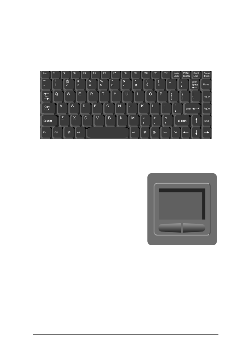
About the Keyboard
This is a standard sized keyboard. Once the console has been connected to the interfacing computer, it functions according to all the
rules of the operating system driving it.
About the Touchpad
This is a standard touchpad pointing
device. Once the unit has been connected to the interfacing computer, it
functions according to the operating system driving it.
Sliding your finger over the touchpad
moves the mouse on-screen. You can
“left-click” either by single-tapping the
pad or clicking the left button. Doubleclick by tapping the pad or clicking the
left button twice.
11
Page 12

Using the Control Panel
The control panel enables you to adjust monitor parameters; raise,
lower, and mute the volume; and select a connected computer in order
to access and control it through the built-in KVM switch.
A
B
CD
A. Up — Increases the volume. However, after pressing the Menu
key, it may be used to scroll up through the available menu options.
B. Down — Decreases the volume. However, after pressing the Menu
key, it may be used to scroll down through the available menu
options.
C. Auto — Automatically sets the monitor defaults for horizontal and
vertical position, brightness, contrast, and screen resolution. As
MRS-815 adjusts the monitor, the message ‘Auto tuning’ appears.
D. Menu — Pressing this button once opens the monitor/audio setup
and adjustment menu. Pressing it again while the menu is open enters
a command.
E. Ports — Press the button corresponding to the port array at the rear
of the MRS-815 to access and control the attached computer.
F. Auto Scan — Press this button to scan the port array and automatically detect which computers are attached.
E. Mute — Turns the sound on and off.
F. Power — Turns the MRS-815 on and off.
E
GHF
12
Page 13

Installation
The MRS-815 unit is designed designed to fit in a standard 19 inch
server rack or cabinet. MRS-815 uses only 1 rack-unit space (1U)
when folded. MRS-815 supports mounting depth of 23½ to 36 inches.
To mount the MRS-815, use the screws that came with your server rack to
mount the brackets onto the rack -- on all four corners -- adjusting the
rear brackets to fit the rack's depth.
Do not over-tighten the screws; otherwise you may strip the threads.
13
Page 14
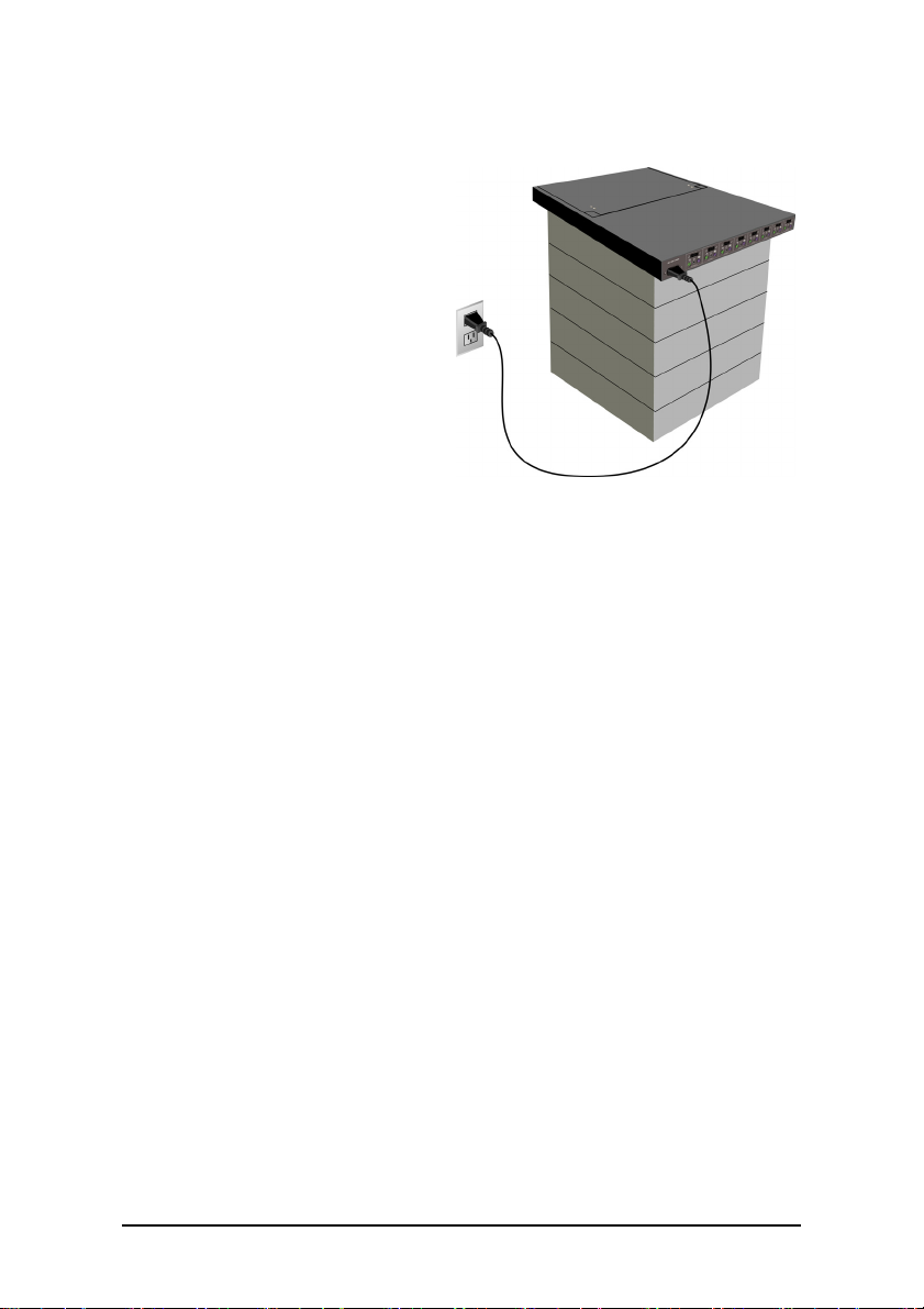
About the Power Supply
The MRS-815 Rack-Mount
Flat Panel Console w/KVM
Switch utilizes a built-in
40-watt AC power adapter.
A
Plug the female end of the
B
MRS-815 cable into the AC
jack at the rear of the case (A).
Plug the male end of the cable
into an available power
socket (B).
Warning! To reduce the risk of injury:
• Do not use the unit near water.
• Do not place the unit on an unstable cart, stand or table.
If the unit falls, it could injure a person or cause
serious damage to the unit.
• Do not overload power outlets or extension cords. An overload
can result in fire or electric shock.
• Do not use an extension cord unless absolutely necessary.
Using an improper extension cord could result in a risk of fire
and electric shock. If an extension cord must be used, make
sure:
– The pins on the extension cord’s plug are of the same number,
size, and shape as those of the plug on the power supply.
– The extension cord is properly wired and in good electrical
condition.
– The extension cord’s wire is at least 18 AWG.
• Do not disassemble the unit. Take the unit to a qualified
service technician when service or repair is required.
Improper reassembly may result in a risk of electric shock or
fire.
14
Page 15

Making the Connection
Once you’ve installed the unit, connect the MRS-815 to the computers you want to control.
1. Turn off the computers to which you want to connect the
MRS-815.
2. Connect the green pointing device PS/2 connector to the
green PS/2 port on the back of the console. Connect the
other end of the PS/2 line to the computer's mouse port.
3. Connect the purple keyboard connector to the purple key-
board port on the back of the console. Connect the other
end of the keyboard line to the computer's keyboard port.
4. Connect the blue VGA connector to the VGA port at the
back of the console. Connect the other end of the
VGA line to the computer.
5. Follow steps 2 through 4 for the remaining computers.
6. Switch on the computers and then switch on the
console. All of the attached computers can now be
accessed and controlled directly through the console.
Note: The keyboard, VGA and mouse
wires are all connected in a single,
integrated unit called the KVM cable.
15
KVM cable
Page 16
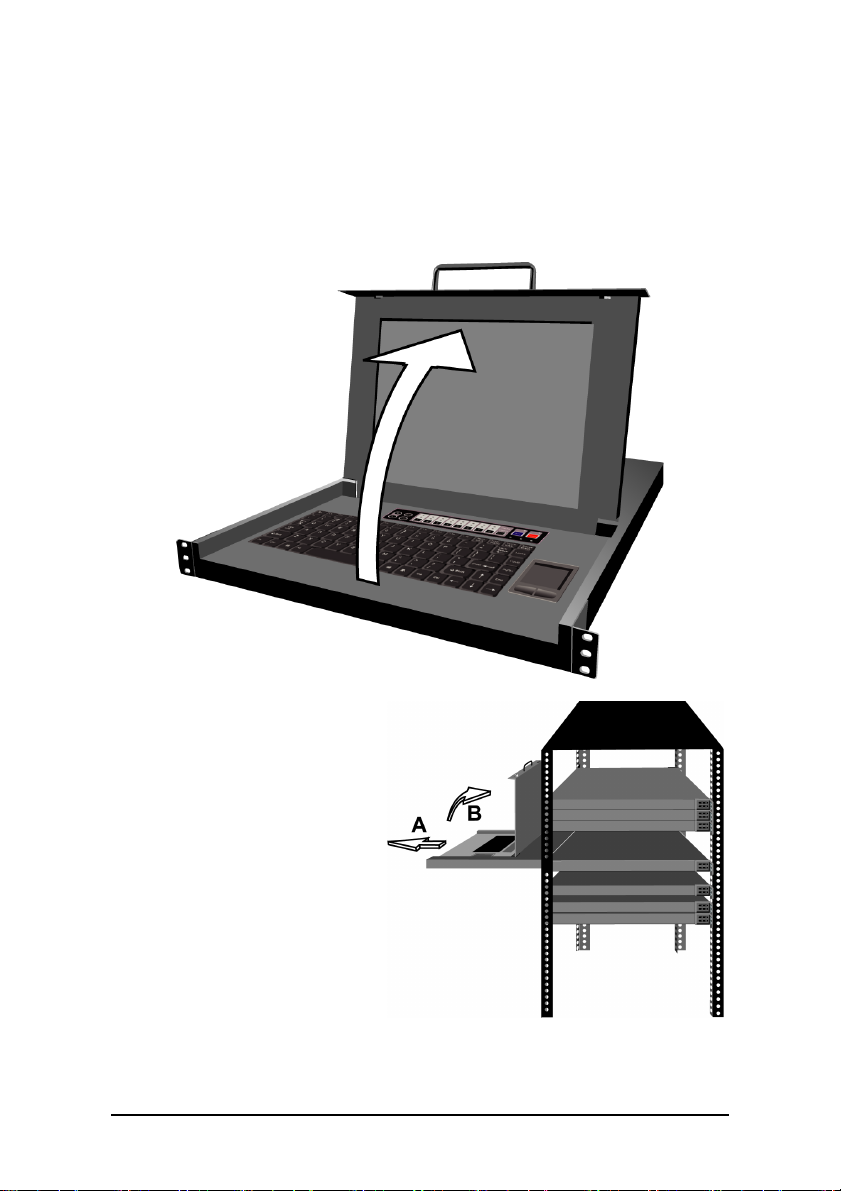
Working with the MRS-815
The MRS-815 is quite simple to use. After unlocking the unit (for
information on doing this, See “Securing the Unit” on page 8),
open it by pulling up on the handle. The monitor, keyboard and touchpad are immediately accessible.
If the MRS-815 is blocked
from above by other devices,
pull the unit out toward
you sliding it away from the
mounted chassis (A), and
open it (B).
When you’re done working
on the MRS-815, remember
to close it, slide the unit
back into the chassis, and
then lock it (See “Securing
the Unit” on page 8).
16
Page 17
Touchpad Driver Installation
On most systems, the MRS-815 touchpad pointing device should
work automatically. Microsoft® Windows® ME, 2000, NT and XP
will detect the device and install generic drivers for it the first time
MRS-815 is connected to a computer with one of these operating systems.
However, if you encounter problems with the touchpad drivers, you
can go to the Windows® support Web site and download updated drivers,
if available.
After downloading the driver installation package, run the setup program and follow the on-screen instructions to complete the process.
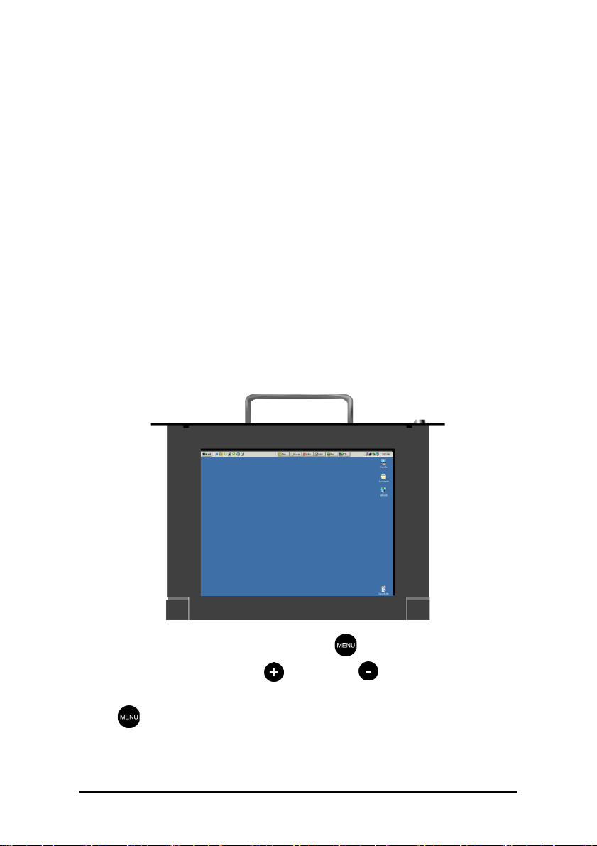
Using the Monitor
The MRS-815 console monitor is functionally identical to a normal
desktop or notebook monitor.
On the keyboard, press the menu button to open the On Screen
Display (OSD). Use the plus and minus buttons to navigate
up and down the OSD menu. When you want to configure an option,
press when the submenu is highlighted.
17
Page 18

OSD Menu Items
Press the menu button on the keyboard to open the OSD menu. The
following are the OSD menu options:
Brightness
Adjusts monitor brightness. Press plus (+) to increase the brightness. Press minus (–) to decrease it. Press menu to exit.
Contrast
Adjusts monitor contrast. Press plus (+) to increase the contrast.
Press minus (–) to decrease it. Press menu to exit.
Display Adjust
Modifies the positioning of the operating system interface on the
display screen. Highlight an option on the Display Adjust submenu and press menu to display the menu items. Options are:
• V- Position: adjusts the vertical position of the screen.
Press plus (+) to move the screen up. Press minus (–) to move
it down.
• H-Position: adjusts the horizontal position of the screen.
Press plus (+) to move the screen left. Press minus (–) to move
it right.
• Pitch: adjusts the noise or distortion of the vertical display
bars. Press plus (+) and minus (–) to adjust the bars.
• Phase: adjusts the noise or distortion of the horizontal display
bars. Press plus (+) and minus (–) to adjust the bars.
• Sharpness: adjusts the clarity of the monitor. Press plus (+) to
increase the sharpness. Press minus (–) to decrease the sharpness.
• Auto Tuning: automatically adjusts the monitor settings
according to the VGA card of the target computer.
• Recall: resets monitor settings to the factory default values.
• Return: after making your adjustments, highlight this item and
press menu to exit.
18
Page 19

Color Temperature
Adjusts the monitor’s color temperature level. Adjust the color
temperature to compensate for ambient light. The three default
temperatures are: 9300 K, 7500 K, and 6500 K. Select User Preset
to set a defined color temperature. Select Recall to load the factory
default settings. Highlight Return and press menu to exit the Color
Temperature submenu.
Language
Sets the OSD language. Options are: English, Spanish, German,
Italian, French, and Chinese. Press plus (+) and minus (–) to highlight the desired language. Press menu to select the language.
Highlight Return and press menu to exit the Language submenu.
OSD Adjust
Adjusts OSD menu options:
• OSD H-Position: adjusts the horizontal position of the OSD
menu on the screen. Press plus (+) to move the OSD menu
right. Press minus (–) to move it left.
• OSD V-Position: adjusts the vertical position of the OSD
menu on the screen. Press plus (+) to move the OSD menu up.
Press minus (–) to move it down.
• OSD Timer: adjusts the amount of time that the OSD menu is
visible. Press plus (+) and minus (–) to adjust the time.
• Te a T i m e: enables an OSD screen saver. Press plus (+) and
minus (–) to adjust the time at which the screensaver starts.
• Recall: resets OSD menu settings to the factory default values.
• Return: after making your adjustments, highlight this item and
press Menu to exit.
19
Page 20

Audio Control
Adjust the volume of the onboard speakers.
• Mute: turns the sound off. Selecting this option a second time
restores the volume.
• Vo lu me : raises and lowers the audio volume. Press plus (+) to
increase the volume. Press minus (–) to decrease the volume.
• Recall: resets audio settings to the factory default values.
• Return: after making your adjustments, highlight this item and
press Menu to exit.
Reset
Restores all settings back to the factory defaults.
Exit
Exits the OSD menu.
20
Page 21

Troubleshooting
The following are answers to some commonly asked questions
regarding problems operating the MRS-815 device.
Q: I can’t open the unit even though I’ve turned the key all the
way to the left.
A: You must press the sliding lock toward the left with your other
hand after you’ve unlocked the key on the right.
Q: The pointing device, keyboard and/or monitor either don’t
work at all or are behaving erratically.
A: Check the KVM cables where they attach to the console and
be sure none of the component wires are loose or detached.
Q: The equipment won’t turn on.
A: Check to make sure the power cord is plugged in completely
and that your power supply matches the MRS-815 device
requirements.
Q: The equipment powers up normally but the monitor displays
nothing and neither the keyboard nor the touchpad respond.
The OSD menu comes up as per normal.
A: Check your connections to the interface computer. Ensure that
the KVM cable is securely connected at both the interface computer and the MRS-815.
Q: There is no sound from the speakers.
A: Check that the audio cable is installed properly. Also check the
drivers on the interface computer to which it is attached.
21
Page 22

Regulatory Notices
Federal Communications Commission (FCC)
This equipment has been tested and found to comply with the limits for a Class A
digital device, pursuant to Part 15 of the FCC rules. These limits are designed to provide reasonable protection against harmful interference when the equipment is operated in a commercial environment. This equipment generates, uses, and can radiate
radio frequency energy and, if not installed and used in accordance with the instructions, may cause harmful interference to radio communications. Operation of this
equipment in a residential area is likely to cause harmful interference in which case
the user will be required to correct the interference at his own expense.
FCC Caution: Assure continued compliance (example - use only shielded interface
cables when connecting to computer or peripheral devices). Any changes or modifications not expressly approved by the party responsible for compliance could void
the user’s authority to operate this equipment.
22
Page 23

CE Notice (European Union)
The symbol indicates compliance of this equipment to the EMC Directive and the
Low Voltage Directive of the European Union. These markings indicate that this system meets the following technical standards:
• EN 55022 — “Limits and Methods of Measurement of Radio Interference
Characteristics of Information Technology Equipment.”
• EN 55024 — “Information technology equipment - Immunity characteristics
- Limits and methods of measurement.”
• EN 61000-3-2 — “Electromagnetic compatibility (EMC) - Part 3: Limits Section 2: Limits for harmonic current emissions (Equipment input current
up to and including 16 A per phase).”
• EN 61000-3-3 — “Electromagnetic compatibility (EMC) -Part 3: Limits Section 3: Limitation of voltage fluctuations and flicker in low-voltage supply systems for equipment with rated current up to and including 16 A.”
• EN 60950 — “Safety of Information Technology Equipment.”
NOTE: EN 55022 emissions requirements provide for two classifications:
• Class A is for typical commercial areas.
• Class B is for typical domestic areas.
To determine which classification applies to your computer, examine the FCC registration label located on the back panel of the computer. If the label indicates a Class
A rating, the following warning applies to your computer:
RF INTERFERENCE WARNING: This is a Class A product. In a domestic environment this product may cause radio frequency (RF) interference, in which case the
user may be required to take adequate measures.
This device is classified for use in a typical Class B domestic environment.
CCC Notice
On Class A systems, the following warning will appear near the regulatory label:
Warning: This is a Class A product. In a domestic environment this product may
cause radio interference, in which case the user may be required to take adequate
measures.
23
Page 24

24
 Loading...