


TO 31R2-2TRC207-1
OPERATION AND MAINTENANCE INSTRUCTIONS
WITH ILLUSTRATED PARTS BREAKDOWN
ORGANIZATIONAL LEVEL
RADIO SET
AN/TRC-207
(BI-DIRECTIONAL REPEATER)
RACAL COMMUNICATIONS, INC.
5 RESEARCH PLACE
ROCKVILLE, MD 20850
CONTRACT NO: F19628-91-D-0012
DISTRIBUTION STATEMENT B - Distribution authorized to U.S. Government agencies only for administrative
or operational use 15 August, 1996. Other requests for this document shall be referred to Sacramento ALC/TILBE,
3200 Peacekeeper Way, Suite 1, McClellan AFB, CA 95652-1026.
WARNING - This document contains technical data whose export is restricted by the Arms Export Control Act (Title
22, U.S.C., Sec 2751 et seq.) or the Export Administration Act of 1979, as amended (Title 50, U.S.C., App 2401 et
seq.). Violations of these export laws are subject to severe criminal penalties.
HANDLING AND DESTRUCTION NOTICE - Handle in compliance with distribution statement and destroy by any
method that will prevent disclosure of contents or reconstruction of the document.
PUBLISHED UNDER AUTHORITY OF THE SECRETARY OF THE AIR FORCE
15 JULY 1997

LIST OF EFFECTIVE PAGES
TO 31R2-2TRC207-1
INSERT LATEST CHANGE PAGES, DESTROY SUPERSEDED PAGES.
NOTE: The portion of the text affected by the changes is indicated by a vertical line
DATES OF ISSUE FOR ORIGINAL AND CHANGED PAGES ARE:
TOTAL NUMBER OF PAGES IN THIS PUBLICATION IS 110 CONSISTING OF THE FOLLOWING:
Page * Change
No. No.
in the outer margin of the page. Changes to illustrations are indicated by a
vertical line adjacent to the illustration identification number.
ORIGINAL 0 15 JULY 1997
Page * Change
No. No.
Page * Change
No. No.
Title page........................ 0
A..................................... 0
i - ix ................................ 0
1-0 - 1-8.......................... 0
2-1 - 2-9.......................... 0
2-10 blank ...................... 0
3-1 - 3-4.......................... 0
4-1 - 4-14........................ 0
5-1 - 5-6.......................... 0
6-1 - 6-13........................ 0
6-14 blank ...................... 0
7-1 - 7-24........................ 0
8-1 .................................. 0
8-2 blank ........................ 0
8-3 .................................. 0
8-4 blank ........................ 0
GLOSSARY-1 ............... 0
GLOSSARY-2 blank...... 0
INDEX-1 - 4................... 0
* Zero in this column indicates an original page.
USAF

TO 31R2-2TRC207-1
TABLE OF CONTENTS
Chapter Page
LIST OF ILLUSTRATIONS.........................................................................................................................................
IV
LIST OF TABLES..........................................................................................................................................................
SAFETY SUMMARY...................................................................................................................................................
FOREWORD.................................................................................................................................................................
VI
IX
CHAPTER 1 GENERAL INFORMATION............................................................................................................1-3
1-1 DESCRIPTION AND PURPOSE.................................................................................................................1-3
1-1.1 Equipment Function and Purpose ........................................................................................................1-3
1-1.2 Equipment Description ........................................................................................................................1-3
1-2 LEADING PARTICULARS .........................................................................................................................1-5
1-3 CAPABILITIES AND LIMITATIONS........................................................................................................1-6
1-4 EQUIPMENT SUPPLIED ............................................................................................................................1-7
1-5 EQUIPMENT REQUIRED BUT NOT SUPPLIED ..................................................................................... 1-8
1-6 SPECIAL TOOLS AND TEST EQUIPMENT.............................................................................................1-8
1-7 RELATED TECHNICAL MANUALS.........................................................................................................1-8
CHAPTER 2 INSTALLATION ............................................................................................................................... 2-1
2-1 INTRODUCTION......................................................................................................................................... 2-1
S
ECTION
I. INSTALLATION LOGISTICS ................................................................................................................2-1
2-2 SITE PREPARATION.................................................................................................................................. 2-1
2-3 UNPACKING AND INSPECTIONS. ..........................................................................................................2-1
2-4 HOUSING.....................................................................................................................................................2-3
2-5 RECEIVING DATA. ....................................................................................................................................2-3
2-6 MATERIAL HANDLING. ........................................................................................................................... 2-3
2-7 CABLES........................................................................................................................................................2-4
2-8 BUILDING AND OTHER SUPPORTING STRUCTURES........................................................................ 2-4
S
ECTION
II. INSTALLATION PROCEDURES ......................................................................................................... 2-5
2-9 SPECIAL TOOLS AND EQUIPMENT REQUIRED FOR FIELD INSTALLATION................................2-5
2-10 INSTALLATION SEQUENCE ....................................................................................................................2-5
2-10.1 Antenna/Mast Installation .................................................................................................................... 2-5
2-10.2 Lithium Battery Installation. ................................................................................................................ 2-9
2-10.3 Ground Rod Installation.......................................................................................................................2-9
2-10.4 External Power Supply.........................................................................................................................2-9
2-10.5 Diplexer Installation.............................................................................................................................2-9
2-10.6 Receiver-Transmitter Transceiver Module Installation........................................................................2-9
V
CHAPTER 3 PREPARATION FOR USE AND RESHIPMENT .........................................................................3-1
3-1 INTRODUCTION......................................................................................................................................... 3-1
S
ECTION
I. PREPARATION FOR USE...................................................................................................................... 3-1
3-2 INSPECTION. .............................................................................................................................................. 3-1
3-3 POST-INSTALLATION CHECKOUT. ....................................................................................................... 3-1
3-3.1 Preliminary...........................................................................................................................................3-1
3-3.2 Alignment and Adjustment. .................................................................................................................3-2
3-3.3 Post-Installation Checkout Procedures ................................................................................................3-2
S
ECTION
II. PREPARATION FOR RESHIPMENT................................................................................................... 3-2
3-4 PREPARING UNIT FOR RESHIPMENT.................................................................................................... 3-2
3-5 PACKING. .................................................................................................................................................... 3-3
3-6 HANDLING AND STORAGE..................................................................................................................... 3-3
3-6.1 Protective Measures for Electrical Connectors....................................................................................3-3
3-6.2 Preparation for Shipment and Storage. ................................................................................................3-3
3-6.3 Handling. .............................................................................................................................................3-3
CHAPTER 4 OPERATION......................................................................................................................................4-1
S
ECTION
I. CONTROLS AND INDICATORS........................................................................................................... 4-1
4-1 INTRODUCTION......................................................................................................................................... 4-1
i

TO 31R2-2TRC207-1
4-2 CONTROLS AND INDICATORS................................................................................................................4-1
4-2.1 Indicators, Controls, and Switches. ......................................................................................................4-1
4-2.2 Power Supply Switches and Connectors. .............................................................................................4-1
4-2.3 Connectors............................................................................................................................................4-1
Diplexer Control................................................................................................................................................4-1
S
ECTION
II. OPERATING INSTRUCTIONS .............................................................................................................4-7
4-3 OPERATING MODES AND FREQUENCY RECOMMENDATIONS ......................................................4-7
4-3.1 Operating Modes..................................................................................................................................4-7
4-3.2 Frequency Recommendations...............................................................................................................4-7
4-4 INITIAL POWER-UP AND DIPLEXER TUNING PROCEDURES.........................................................4-11
4-5 RECEIVING AND RETRANSMITTING MESSAGES.............................................................................4-12
4-6 COVERT OPERATIONS............................................................................................................................4-13
4-7 RECEIVER-TRANSMITTERS ..................................................................................................................4-13
4-8 EQUIPMENT SHUTDOWN ......................................................................................................................4-13
S
ECTION
III. EMERGENCY OPERATION..............................................................................................................4-13
4-9 EMERGENCY POWER..............................................................................................................................4-13
4-10 ELECTROMAGNETIC PULSE PROTECTION........................................................................................4-13
4-10.1 EMP Susceptibility.............................................................................................................................4-13
4-10.2 EMP Protective Measures ..................................................................................................................4-13
4-11 NUCLEAR, BIOLOGICAL, AND CHEMICAL (NBC) CONTAMINATION..........................................4-14
CHAPTER 5 THEORY OF OPERATION ............................................................................................................ 5-1
S
ECTION
I. FUNCTIONAL SYSTEM(S) OPERATION ............................................................................................5-1
5-1 GENERAL.....................................................................................................................................................5-1
5-2 FUNCTIONAL SYSTEM(S) OPERATION.................................................................................................5-1
5-2.1 +15V DC-DC Converter Circuit Card Assembly (CCA) (A1A1) ........................................................5-1
5-2.2 Repeater Control/Audio Circuit Card Assembly (CCA) (A1A2).........................................................5-1
5-2.3 Repeater Interface CCA (A1A3) ..........................................................................................................5-1
5-2.4 Parent Board Circuit Card Assembly (CCA) (A1A4) ..........................................................................5-1
5-2.5 Control Panel (A1A5) ..........................................................................................................................5-1
5-2.6 RF Power Amplifier Assembly (A1A6) ...............................................................................................5-1
5-2.7 RF Matrix CCA (A1A7).......................................................................................................................5-2
5-2.8 Receiver-Transmitters ..........................................................................................................................5-2
5-2.9 Antenna System....................................................................................................................................5-3
5-2.10 Diplexer (A3) .......................................................................................................................................5-3
5-2.11 AC/DC Power Supply (A2)..................................................................................................................5-3
S
ECTION
II. FUNCTIONAL OPERATION OF ELECTRONIC CIRCUITS..............................................................5-3
5-3 REPEATER CONTROL/AUDIO CIRCUIT CARD ASSEMBLY (CCA) (A1A2)......................................5-3
5-4 15 WATT POWER AMPLIFIER ASSEMBLY (A1A6) ..............................................................................5-4
S
ECTION
III. FUNCTIONAL OPERATION OF MECHANICAL ASSEMBLIES.....................................................5-4
CHAPTER 6 MAINTENANCE............................................................................................................................... 6-1
6-1 GENERAL.....................................................................................................................................................6-1
6-2 OPERATIONAL CHECKOUT.....................................................................................................................6-1
6-2.1 Power-up Verification..........................................................................................................................6-1
6-2.2 Display Off Control..............................................................................................................................6-1
6-2.3 Radio A Tune Mode Verification.........................................................................................................6-2
6-2.4 Radio B Tune Mode Verification.........................................................................................................6-2
6-2.5 Fault LED.............................................................................................................................................6-3
6-3 SERVICING..................................................................................................................................................6-3
6-3.1 Servicing Intervals................................................................................................................................6-3
6-3.2 Inspection. ............................................................................................................................................6-3
6-3.3 Preventive Maintenance. ......................................................................................................................6-3
6-4 TROUBLESHOOTING.................................................................................................................................6-4
6-5 REMOVAL/REPLACEMENT PROCEDURES ...........................................................................................6-9
6-5.1 Removal/Replacement Procedures - Operator......................................................................................6-9
6-5.2 Removal/Replacement Procedures - Repair Specialist.......................................................................6-12
ii

TO 31R2-2TRC207-1
CHAPTER 7 ILLUSTRATED PARTS BREAKDOWN........................................................................................7-1
S
ECTION
I. INTRODUCTION .................................................................................................................................... 7-1
7-1 GENERAL ....................................................................................................................................................7-1
7-2 MAINTENANCE PARTS LIST................................................................................................................... 7-1
7-3 NUMERICAL INDEX.................................................................................................................................. 7-2
7-4 REFERENCE DESIGNATION INDEX.......................................................................................................7-3
7-5 ELECTROSTATIC DISCHARGE (ESD) SENSITIVE DEVICES. ............................................................7-3
7-6 CAGE CODE SUMMARY........................................................................................................................... 7-4
S
ECTION
II. MAINTENANCE PARTS LIST ............................................................................................................. 7-8
CHAPTER 8 CIRCUIT DIAGRAMS......................................................................................................................8-1
8-1 SCOPE ..........................................................................................................................................................8-1
GLOSSARY
ALPHABETICAL INDEX
iii

TO 31R2-2TRC207-1
LIST OF ILLUSTRATIONS
Figure Page
Figure 1-1. Radio Set AN/TRC-207........................................................................................................................... 1-0
Figure 1-2. Receiver-Transmitter RT-1695/TRC-199................................................................................................ 1-4
Figure 1-3. BDR Diplexer.......................................................................................................................................... 1-4
Figure 2-1. Packaging Diagram for the BDR ............................................................................................................. 2-2
Figure 2-2. Antenna Mast/Antenna Installation (Sheet 1 of 6).................................................................................. 2-5
Figure 2-3. Antenna Mast/Antenna Installation (Sheet 2 of 6).................................................................................. 2-6
Figure 2-4. Antenna Mast/Antenna Installation (Sheet 3 of 6).................................................................................. 2-6
Figure 2-5. Antenna Mast/Antenna Installation (Sheet 4 of 6).................................................................................. 2-7
Figure 2-6. Antenna Mast/Antenna Installation (Sheet 5 of 6)................................................................................... 2-7
Figure 2-7. Antenna Mast/Antenna Installation (Sheet 6 of 6)................................................................................... 2-8
Figure 4-1. Location of Bi-Directional Repeater Indicators, Controls, and Switches ................................................ 4-1
Figure 4-2. Location of Power Supply Switches (Power Supply Top View) ............................................................. 4-3
Figure 4-3. Location of Power Supply Connectors (Power Supply Side View)......................................................... 4-4
Figure 4-4. Location of Bi-Directional Repeater Unit Connectors............................................................................. 4-5
Figure 4-5. Location of Bi-directional Repeater Diplexer Controls........................................................................... 4-6
Figure 4-6. Standard BDR Cabling Set-up............................................................................................................... 4-10
Figure 4-7. BDR Cross-Banding Cabling Set-up ..................................................................................................... 4-10
Figure 5-1. Bi-directional Repeater System, Functional Block Diagram ................................................................... 5-2
Figure 5-2. Repeater Control/Audio CCA (A1A2), Functional Block Diagram ........................................................5-5
Figure 5-3. 15 Watt Power Amplifier Assembly (A1A6), Functional Block Diagram............................................... 5-6
Figure 6-1. Detail of diplexer shock mount assembly .............................................................................................. 6-11
Figure 7-1. Radio Set AN/TRC-207 (Sheet 1 of 2)................................................................................................... 7-8
Figure 7-2. Bi-directional Repeater Assembly (4101027-501) (Sheet 1 of 3) ......................................................... 7-13
Figure 7-3. Power Amplifier Assembly, 15W (SS-4100853-501) ........................................................................... 7-19
Figure 8-1. Radio Set AN/TRC-207, Interconnection Diagram................................................................................. 8-3
iv

TO 31R2-2TRC207-1
LIST OF TABLES
Table Page
Table 1-1. BDR Configurations (by Frequency Band) ...............................................................................................1-3
Table 1-2. Leading Particulars....................................................................................................................................1-5
Table 1-3. Capabilities and Limitations......................................................................................................................1-6
Table 1-4. Equipment Supplied ..................................................................................................................................1-7
Table 1-5. Equipment Required but Not Supplied......................................................................................................1-8
Table 1-6. Related Technical Manuals .......................................................................................................................1-8
Table 2-1. BDR Packaging.........................................................................................................................................2-3
Table 2-2. BDR Interconnecting Cables.....................................................................................................................2-4
Table 2-3. External Power Supply Switch Settings ....................................................................................................2-9
Table 4-1. Description of Indicators, Controls and Switches .....................................................................................4-2
Table 4-2. Description of Power Supply Switches .....................................................................................................4-3
Table 4-3. Description of Power Supply Connectors..................................................................................................4-4
Table 4-4. Description of Repeater Unit Connectors..................................................................................................4-5
Table 4-5. Description of Diplexer Controls .............................................................................................................. 4-6
Table 4-6. TR Simplex Mode Recommended Frequencies ........................................................................................4-8
Table 4-7. TR Half-Duplex Mode Recommended Frequencies..................................................................................4-8
Table 4-8. Single BDR Recommended Frequencies...................................................................................................4-8
Table 4-9. Tandemed BDR Recommended Frequencies............................................................................................4-9
Table 5-1. Antenna System Frequency Band Vs Gain................................................................................................5-3
Table 6-1. Initial Switch and Control Settings for Power-Up Verification.................................................................6-1
Table 6-2. Initial Switch and Control Settings for Radio A Tune Mode Verification ................................................6-2
Table 6-3. Initial Switch and Control Settings for Radio B Tune Mode Verification.................................................6-2
Table 6-4. Recommended Service Intervals ...............................................................................................................6-3
Table 6-5. Organizational Maintenance Guide - Operator..........................................................................................6-5
Table 6-6. Organizational Maintenance Guide - Repair Specialist............................................................................. 6-8
Table 6-7. Cross-Reference to Removal/Replacement Procedures............................................................................. 6-9
Table 7-1. Radio Set AN/TRC-207 ..........................................................................................................................7-10
Table 7-2. Bi-directional Repeater Assembly (4101027-501)..................................................................................7-16
Table 7-3. Power AMP Assembly, 15W (SS-4100853-501)....................................................................................7-20
v
TO 31R2-2TRC207-1
SAFETY SUMMARY
The following are general safety precautions that are not related to any specific procedure, and do not appear elsewhere
in this manual. These Safety Summaries are recommended precautions that all personnel must understand and apply
during any given phase of operation and maintenance. Each chapter has other specific warnings and cautions.
WARNING
KEEP AWAY FROM LIVE CIRCUITS
Personnel must at all times observe all safety regulations. Do not replace components or make
adjustments inside equipment with power turned on. Under certain conditions, dangerous
voltages may exist when the power switch is in the off position due to charges retained by
capacitors. To avoid injury, always remove power and discharge and ground a circuit before
touching it.
RESUSCITATION
Personnel working with or near high voltages should be familiar with modern methods of
resuscitation. Such information may be obtained from the Director of Base Medical Services.
WARNING
LITHIUM BATTERIES
Lithium oxide batteries or cells may be used in the battery enclosure and receiver-transmitters used in this equipment.
They are potentially hazardous if misused or tampered with before, during or after discharge. The following precautions
must be strictly observed to prevent possible injury to personnel or equipment damage.
heat, incinerate, crush, puncture, disassemble, or otherwise mutilate the batteries.
Do not
short-circuit, recharge, or bypass internal fuse.
Do not
Do not store batteries in equipment during long periods of non-use (in excess of 30 days).
Turn off
venting (hissing sounds), or smell irritating sulfur dioxide gas.
vi
the equipment immediately if you detect battery compartment becoming unduly hot, hear battery cells

TO 31R2-2TRC207-1
WARNING
VOLTAGES WITHIN THIS EQUIPMENT ARE HIGH ENOUGH TO ENDANGER LIFE.
Covers are not to be removed except by persons qualified and authorized to do so and these persons should always take
extreme care once the covers have been removed.
Page
2-1 WARNING - Installation of the bi-directional repeater requires a minimum of two people.
2-1 WARNING - Removing the bi-directional repeater assembly from the shipping carton requires a
minimum of two persons.
2-5 WARNING - Ensure proper use of safety tools (work gloves and hard hat) during assembly and
disassembly of antenna.
2-6 WARNING - Before using the hammer, ensure a wedge is placed in the top of the hammer so that the
hammer head does not come loose, thereby endangering personnel.
3-3, 6-10,
6-12
6-11 WARNING - This equipment is capable of generating RF power sufficient to cause RF burns. During
2-1 CAUTION - Exercise care when removing units from packing material in order to prevent damage to the
3-3 CAUTION - Never apply pressure sensitive tape directly to connectors. This could damage connector
3-3 CAUTION - Package all electrostatic discharge (ESD) sensitive assemblies in ESD bags before shipping
3-3 CAUTION - Rough handling may cause unnecessary damage to electronic assemblies.
3-3 CAUTION - Electronic assemblies containing solid-state devices are susceptible to damage from static
3-3 CAUTION - Forcing any tilted or cocked electronic assembly into position may result in bent or broken
3-4 CAUTION - When repairing an electronic assembly, be careful that the tool employed does not
3-4 CAUTION - Because of the miniaturization of parts for electronic assembly construction, the leads,
WARNING - Before performing removal/replacement procedures, make sure power is removed from
the unit by disconnecting from power source. Failure to do so could result in personal injury or
equipment damage.
transmit, care should be taken to eliminate the possibility of touching exposed RF output points such as
the center conductors of coaxial cables or antenna feedpoints.
unit.
pins.
or storing.
electrical discharges. Wear protective clothing and grounded wrist straps
pins.
inadvertently press against leads, pins, or other parts that are easily bent.
connectors, and pins have been stiffened to make them more rugged. As a result, such parts are brittle
and will break easily if bent too often or pulled on too hard. When handling an assembly that has been
removed from its chassis, be careful not to press against the leads and pins. When removing an assembly,
be sure to pull it straight out from the equipment. Do not cock, twist, pry, or carelessly jerk an electronic
assembly to remove it from the mounting or connector.
3-4 CAUTION - The bi-directional repeater contains components that are susceptible to damage by static
electrical charges. Disassembly of the bi-directional repeater should only be done at a properly grounded
work station.
6-12 CAUTION - The bi-directional repeater contains components that are susceptible to damage by static
electrical charges. Disassembly of the bi-directional repeater should only be done at a properly grounded
work station.
vii

TO 31R2-2TRC207-1
This page left blank intentionally.
viii

TO 31R2-2TRC207-1
FOREWORD
This manual meets the technical content requirements of specification MIL-M-38798B, paragraph 3.3 (1 December 1975)
and MIL-M-38807A (1 June 1982) and format requirements of specification MIL-M-38784B (16 April 1983) for the bidirectional repeater.
a. Chapter 1 - General Information. This chapter provides general information for the bi-directional repeater
including equipment description and purpose, leading particulars, capabilities and limitations, equipment
supplied, equipment required but not supplied, optional equipment, special tools and test equipment, and
related technical manuals.
b. Chapter 2 - Installation. This chapter provides complete installation instructions for the receiver-transmitter
including installation logistics and installation procedure.
c. Chapter 3 - Preparation for Use and Reshipment. This chapter contains information which will permit
operation and maintenance personnel to prepare the equipment for use, including reference to postinstallation checkout procedures, preparing the unit for reshipment, packing, handling, and storage
procedures.
d. Chapter 4 - Operation. This chapter provides complete operating instructions for the bi-directional repeater.
e. Chapter 5 - Theory of Operation. This chapter provides complete theory of operation for the bi-directional
repeater.
f. Chapter 6 - Maintenance. This chapter provides all instructions required for on-equipment and off-
equipment maintenance of the bi-directional repeater. It includes preventive maintenance, troubleshooting
procedures, and repair procedures.
g. Chapter 7 - Illustrated Parts Breakdown (IPB). The IPB provides complete illustrated parts breakdown for
the bi-directional repeater. The IPB is prepared in accordance with MIL-M-38807A.
h. Chapter 8 - Circuit Diagrams. This chapter contains the BDR interconnection diagram.
i. Glossary - The glossary provides a definition of the special terms and abbreviations used in the technical
order.
j. Alphabetical Index - The index provides cross-references to applicable paragraphs, figures or tables.
ix
TO 31R2-2TRC207-1
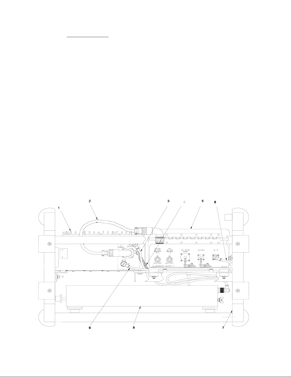
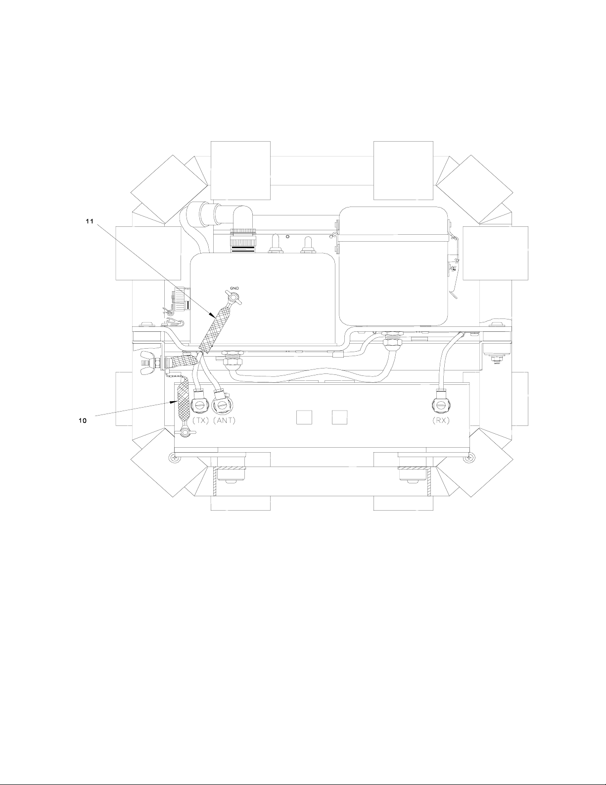
Legend for Figure 1-1:
1. Bi-directional Repeater (BDR) Assembly (A1)
2. Cable Assembly, PS Power (W1)
3. Cable Assembly, Coaxial, RF (W2)
4. Strap Assembly, Ground (W5)
5. Power Supply (A2) (includes Power Supply Enclosure and Battery Enclosure)
6. Cable Assembly, Coaxial, RF (W4)
7. Weldment, Repeater Frame
8. Diplexer Assembly, 30-88 MHz (A3)
9. Cable Assembly, Coaxial, RF (W3)
10. Strap Assembly, Ground (W6)
11. Strap Assembly, Ground (W7)
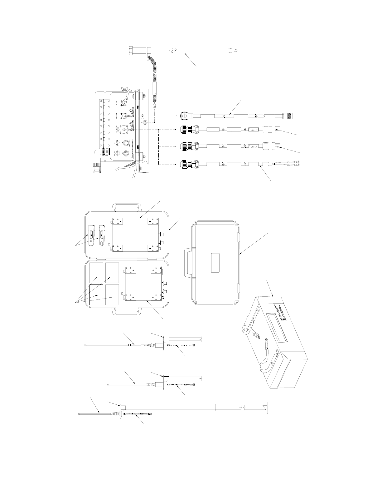
12. Antenna, 403-470 MHz
13. Antenna, Mast, TR
14. Antenna, 136-174 MHz
15. Antenna, 30-88 MHz
16. Receiver-Transmitter RT-1695/TRC-199 Unit (A4, A5)
16a. Additional transceiver modules (p/o Receiver-Transmitter RT-1695/TRC-199)
17. Diplexer Assembly, 136-174 MHz (A3)
18. Case, Transit, Diplexer
19. Diplexer Assembly, 403-470 MHz (A3)
20. Rod Assembly, Ground
21. Cable, Coaxial, Antenna (W10)
22. Cable Assembly, 240 VAC, Power (W9)
23. Cable Assembly, 120 VAC, Power (W9)
24. Cable Assembly, 10-32 VDC, Power (W9)
25. Case, Transit, Diplexer
26. Cover, Frame
1-0
Figure 1-1. Radio Set AN/TRC-207
(Sheet 1 of 3)
TO 31R2-2TRC207-1
Figure 1-1. Radio Set AN/TRC-207
(Sheet 2 of 3)
1-1
TO 31R2-2TRC207-1
16
20
21
22
23
24
17
18
25
16
26
a
19
15
14
12
13
13
21
13
21
1-2
21
Figure 1-1. Radio Set AN/TRC-207
(Sheet 3 of 3)

TO 31R2-2TRC207-1
CHAPTER 1 GENERAL INFORMATION
1-1 DESCRIPTION AND PURPOSE.
1-1.1 Equipment Function and Purpose
Radio Set AN/TRC-6728 (hereinafter referred to as the bi-directional repeater or BDR) is a communications unit capable
of operating in the 30-88, 136-174, or 403-470 Megahertz (MHz) frequency bands. It is used to extend the
communications range of fixed, mobile, or portable receiver-transmitters. The BDR is COMSEC (Communications
Security) transparent and provides repeater capability for all modes without the need for COMSEC encryption/decryption.
1-1.2 Equipment Description
(See Figure 1-1.) The BDR includes a bi-directional repeater assembly, two non-CCI (Controlled Cryptographic Item)
Receiver-Transmitter Sets, Radio RT-1695/TRC-199 (hereinafter referred to as the receiver-transmitters), three antenna
systems, an antenna mast, three diplexers, a tubular (weldment) frame, a power supply enclosure, and a battery enclosure.
1-1.2.1 BDR Unit.
(See Figure 7-2.) The BDR unit includes three circuit card assemblies (CCAs) that are accessible through a removable
cover on the underside of the unit. These are the +15 volt (V) DC-DC converter CCA (A1), repeater control/audio CCA
(A2), and repeater interface (A3). These CCAs plug into the parent board (A4), which interfaces with the control panel
assembly (A5), power amplifier assembly (A6), the RF matrix CCA (A7), the external power supply, and the plug-in
receiver-transmitters. The receiver-transmitters plug into sleeves (A8, A9) located on the left and right sides of the front
panel of the BDR unit. The power amplifier (A6) is mounted under a heatsink on top of the BDR unit.
1-1.2.2 Receiver-Transmitters.
(See Figure 1-2.) The receiver-transmitters provide transmit/receive communication in the 30-88, 136-174, or 403-470
MHz frequency bands. The operating band of the receiver-transmitters is determined by the transceiver module installed.
When the transceiver modules are changed, the BDR must be fitted with the proper antenna and diplexer. The proper
configurations are listed in Table 1-1.
Table 1-1. BDR Configurations (by Frequency Band)
Frequency Band Receiver-Transmitter Antenna Diplexer
30-88 MHz
136-174 MHz
403-470 MHz
The CCI Receiver-Transmitter RT-1696/U(C) is mechanically different from the RT-1695/TRC199 to prevent full insertion into the BDR sleeves to avoid the possibility of leaving a CCI radio
in an unattended repeater.
1-1.2.3 Antenna Assembly.
The BDR antenna system provides half-duplex transmit and receive capability over one of three bands of operation. The
selected antenna is mast mounted. Three antennas are provided to cover the three bands of operation. Refer to Table 1-1.
A mast is provided to elevate the selected antenna up to 10 feet (in 5 foot increments) to increase transmission range and
quality of transmitted and received signals. The antennas and mast can be installed on a roof or existing tower to further
increase range.
SS-4100820-501
SS-4100821-501
SS-4100822-501
4242-MK2-RAC
4265-RAC
4266-RAC
NOTE
SS-1600322-501
SS-1600322-502
SS-1600322-503
1-3
TO 31R2-2TRC207-1
Figure 1-1Figure 1-2. Receiver-Transmitter RT-1695/TRC-199
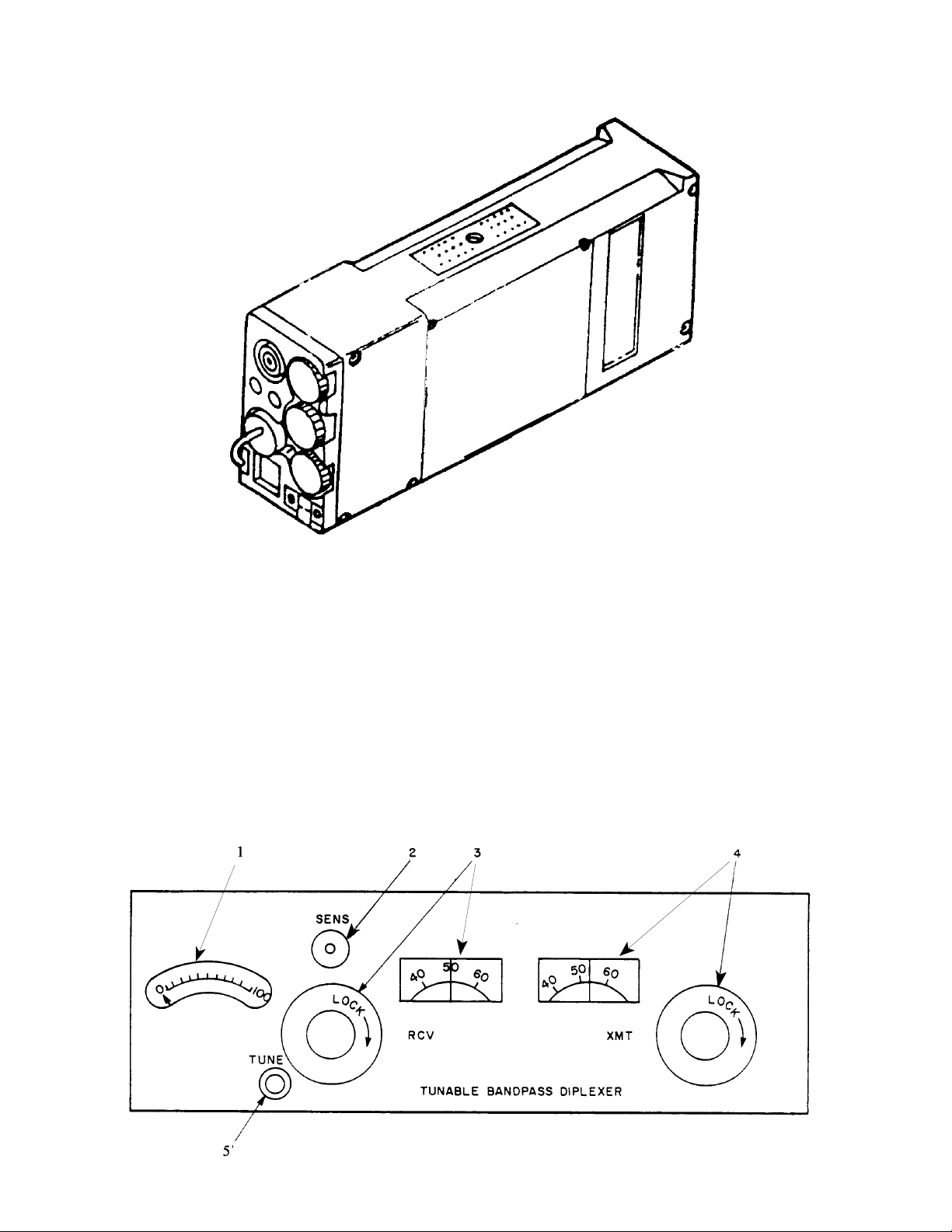
1-1.2.4 Diplexer.
(See Figure 1-3.) The BDR diplexer provides a method of using a receiver and a transmitter on a common antenna. The
diplexer has three coaxial connector ports - one port connects to the antenna via the power supply and the other two
connect to the Radio A and Radio B ports on the BDR. The diplexer, when properly tuned, provides a transmitter-toreceiver isolation of 70 decibels (dB) at any frequency spacing of 4 MHz or 3% of the operating frequency, whichever
is greater. There are three separate diplexers, one for each frequency band. The frequency band of the diplexer must
correspond to that of the receiver-transmitter and antenna.
Legend for Figure 1-3
(136-174 MHz and 403-470 MHz diplexers have the same controls, but their appearance is slightly different):
1. Tuning Meter 3. RCV Frequency Meter and Tuning Knob 5. TUNE Pushbutton
2. SENS Control 4. XMT Frequency Meter and Tuning Knob
1-4
Figure 1-3. BDR Diplexer

TO 31R2-2TRC207-1
1-1.2.5 Power Supply Assembly.
The power supply assembly provides power for the operation of the BDR. The power supply will operate from any direct
current (DC) voltage between 10 and 32 volts and from 120/240 or 220 volts alternating current (VAC). The operation
of the power supply is controlled by the AC/OFF/DC and internal/external (INT/EXT) DC switches on the power supply.
The power supply assembly consists of the power supply enclosure and the battery enclosure, which are mounted on a
tray that is bolted to the BDR frame. There are two circuit breakers located on the side of the power supply enclosure
that must be in the ON position for BDR operation.
1-1.2.5.1 Power Supply Enclosure.
The power supply enclosure provides the BDR with regulated 28 VDC power and unregulated 15 VDC power. The
power supply enclosure includes a +28V DC-DC converter CCA (A2) and circuit breakers for the AC and DC input lines.
1-1.2.5.2 Battery Enclosure.
The battery enclosure is a weather-resistant container that can hold up to four of either Type BA-5590/U Lithium batteries
or Type BB-590/U NiCd batteries. The battery connectors are mounted in the bottom of the battery enclosure box. (For
battery installation see paragraph 2-10.2.)
1-2 LEADING PARTICULARS
Leading particulars for the BDR are given in Table 1-2.
Table 1-2. Leading Particulars
Characteristic Parameter
Equipment dimensions and weight
(BDR assembly - does not include antennas,
antenna cable, or mast):
Length
Width
Height
Volume
Weight (30-88 MHz configuration BDR unit w/radios, power supply,
diplexer, frame)
Environmental requirements:
Temperature:
Operating
Storage
Humidity
Electrical power requirements 10V to 32V DC Battery Power
Nominal power consumption 24 VDC
28.4 inches (in.) (72.0 centimeters (cm))
18.9 in. (48.0 cm)
18.9 in. (48.0 cm)
10145 cubic in. (166,247 cubic cm)
140.0 pounds (lbs) (63.5 kilograms (kg))
-40° Celsius (C) (-40° Fahrenheit (F)) to +49° C (120°F)
-51° C (-60° F) to +68° C (155° F)
0 to 95 percent relative humidity
120/240 " 10% (1 phase, 3 wire) at 50/60 Hertz (Hz)
220 VAC " 10% (1 phase, 3 wire) at 50 Hz
Transmit 2W - 2500 mA
Transmit 10W - 5000 mA
Standby - 500 mA
1-5

TO 31R2-2TRC207-1
1-3 CAPABILITIES AND LIMITATIONS
Capabilities and limitations of the BDR are given in Table 1-3.
Table 1-3. Capabilities and Limitations
Characteristic Parameter
Frequency Range (RCV and XMT) 30-88 MHz
136-174 MHz
403-470 MHz
Transmitter Output 2 and 10 watts selectable
Security BDR is COMSEC transparent (contains no COMSEC
equipment). Equipment will receive and re-transmit analog
(nonsecure), 12 kbps (secure), and 16 kbps (secure) FM signals
Interoperability Radio Set AN/PRC-139/U (C)
AN/PRC-77 Manpack Radio
Radio Set AN/PRC-128
Radio Set AN/GRC-238
Adapter Group OF-228/U
Radio Set AN/TRC-199
SINCGARS-V (single channel)
FED-STD-1023 compatible, 12 kbps secure voice
VINSON (KY-57) compatible, 16 kbps secure voice
Analog 12.5 and 25 kHz frequency modulated (FM) radios
Receiving/Transmitting 25 kilohertz (kHz) Bandwidth on all frequency bands
12.5 kHz Bandwidth on 136-174 MHz and 403-470 MHz
bands
12.5 kHz tuning steps
Channels (receive and transmit) 14 channels each programmable with frequency bandwidth,
output power, and squelch tones as variables (squelch tones
available only in receive)
Adjacent Channel Selectivity 50 dB over 30-88 MHz, 25.0 kHz Bandwidth
52 dB over 136-174 MHz, 12.5 kHz Bandwidth
60 dB over 136-174 MHz, 25.0 kHz Bandwidth
40 dB over 403-470 MHz, 12.5 kHz Bandwidth
48 dB over 403-470 MHz, 25.0 kHz Bandwidth
Sensitivity
Spurious Response and Image Rejection 65 dB.
Intermodulation Spurious Response 60 dB.
Analog (nonsecure) voice: -113 dBm or 0.50µV for 12 dB
SINAD.
Digital: -105 dBm.
1-6

1-4 EQUIPMENT SUPPLIED
Equipment supplied with Radio Set AN/TRC-207 is listed in Table 1-4.
Table 1-4. Equipment Supplied
Official Nomenclature Part Number Quantity
TO 31R2-2TRC207-1
BDR Assembly
Power Supply Assembly
$ Power Supply Enclosure
$ Battery Enclosure
Diplexer Assembly, 30-88 MHz
Diplexer Assembly, 136-174 MHz
Diplexer Assembly, 403-470 MHz
Antenna, 30-88 MHz
Antenna 136-174 MHz
Antenna, 403-470 MHz
Mast, Antenna BDR
Case, Transceiver
Ground Rod Assembly
Receiver/Transmitter Set,
$ Radio RT-1695/TRC-199
$$ System Module, w/o COMSEC
$$ Transceiver Module, 30-88 MHz
$$ Transceiver Module, 136-174 MHz
$$ Transceiver Module, 403-470 MHz
Cable Assembly, BDR Power
Cable Assembly, Coaxial, RF
Cable Assembly, Coaxial, RF
Cable Assembly, Coaxial, RF
Strap Assembly, Ground
Strap Assembly, Ground
Strap Assembly, Ground
Cable Assembly, Power Supply, 120 VAC Input
Cable Assembly, Power Supply, 240 VAC Input
Cable Assembly, Power Supply, DC
Cable Assembly, Coaxial, Antenna
Bumpers, Tactical repeater Frame
Bushing, Shock Mount
Clamp, Rear
Clamp, Front
Frame, Weldment
Case, Transit, Diplexer
Case, Transit, Diplexer
Cover, Frame
4101027-501
4101028-501
SS-1600322-501
SS-1600322-502
SS-1600322-503
4242-MK2-RAC
4265-RAC
4266-RAC
SP10SS
SS-3100552-501
SS-3100551-501
SS-4100807-512
SS-4100819-502
SS-4100820-501
SS-4100821-501
SS-4100822-501
4500117-501
SS-3500292-504
SS-3500292-505
SS-3500292-503
SS-3500279-502
SS-3500279-503
SS-3500279-504
SS-4500107-501
SS-4500108-501
SS-4500109-501
CPRG223/U-30-XX
SS-3400353-1
SS-2400577-1
SS-3100546-501
SS-3400355-1
SS-4400225-1
275-160-100-000
275-160-070-000
IC-3300RC
1
1
1
1
1
1
1
1
1
2
1
2
2
2
2
2
1
1
1
1
1
1
1
1
1
1
1
24
8
1
1
1
1
1
1
1-7

TO 31R2-2TRC207-1
1-5 EQUIPMENT REQUIRED BUT NOT SUPPLIED
Table 1-5 lists equipment required but not supplied.
Table 1-5. Equipment Required but Not Supplied
Equipment Part Number
Programmer Unit, Frequency Radio MX-11531/U SS-4100797-501
Cloning Cable SS-3500272-501
Antenna Cable (for cross-banding operation) CPRG223/U-30-XX
Antenna Mast Kit (for cross-banding operation) SP10SS
Batteries (if internal DC power operation selected) Lithium Type BA-5590/U or NiCad
Type BB-590/U
NiCad Battery Charger/Conditioner (if NiCad BB-590/U
batteries used)
MRC-590
1-6 SPECIAL TOOLS AND TEST EQUIPMENT
There are no special tools or test equipment required for maintenance.
1-7 RELATED TECHNICAL MANUALS
Table 1-6 lists related technical manuals.
Table 1-6. Related Technical Manuals
Publication Number Publication Title
31R2-2PRC139-1 Operation and Maintenance Instructions with Illustrated Parts Breakdown
(Organizational Level) for Radio Set AN/PRC-139(C) (includes
RT-1695/TRC-199, RT-1696/U (C), Programmer Unit, Frequency, Radio
MX-11531/U, Battery Chargers, and Battery Reconditioner)
31R2-2GRC238-1 Operation and Maintenance Instructions with Illustrated Parts Breakdown
(Organizational Level) for Radio Set AN/GRC-238
31R2-4-1085-1 Operation and Maintenance Instructions with Illustrated Parts Breakdown
(Organizational Level) for Adapter Group OF-228/U
31R2-2TRC207-1 Operation and Maintenance Instructions with Illustrated Parts Breakdown
(Organizational Level) for Radio Set AN/TRC-207
31R2-2PRC-139-06 Work Unit Code Manual
35C3-2-113-2 NiCad Battery Reconditioner, MRC-590
1-8

TO 31R2-2TRC207-1
CHAPTER 2 INSTALLATION
2-1 INTRODUCTION.
This section is divided into two sections. Section I. Installation Logistics provides information for site preparation,
unloading, unpacking, and inspections, housing, receiving data, material handling, cabling, and buildings and other
structures. Section II. Installation Procedures lists tools and equipment required for field installation and describes the
installation sequence.
Section I. INSTALLATION LOGISTICS
WARNING
Installation of the BDR requires a minimum of two people.
2-2 SITE PREPARATION.
Select an operating site that is free of obstruction and has access to one of the electrical power sources specified in Table
1-2 under Electrical Requirements. The selected operating area must have sufficient room to accommodate the 9583 cubic
inch volume of the BDR assembly. The antenna should be at least two antenna lengths (e.g., 44 feet for 30-88 MHz) from
power lines and other antennas, etc.
2-3 UNPACKING AND INSPECTIONS.
CAUTION
Exercise care when removing units from packing material in order to prevent damage to the unit.
WARNING
Removing the BDR assembly from the shipping carton requires a minimum of two persons.
To unpack the BDR, remove the unit and any equipment from the carton and store the packing and carton for
reuse/shipment. Packing instructions are given in Chapter 3. Inspect contents for completeness, integrity, and damage.
Contents shall be in accordance with the packing slips and the list of supplied equipment in Table 1-4.
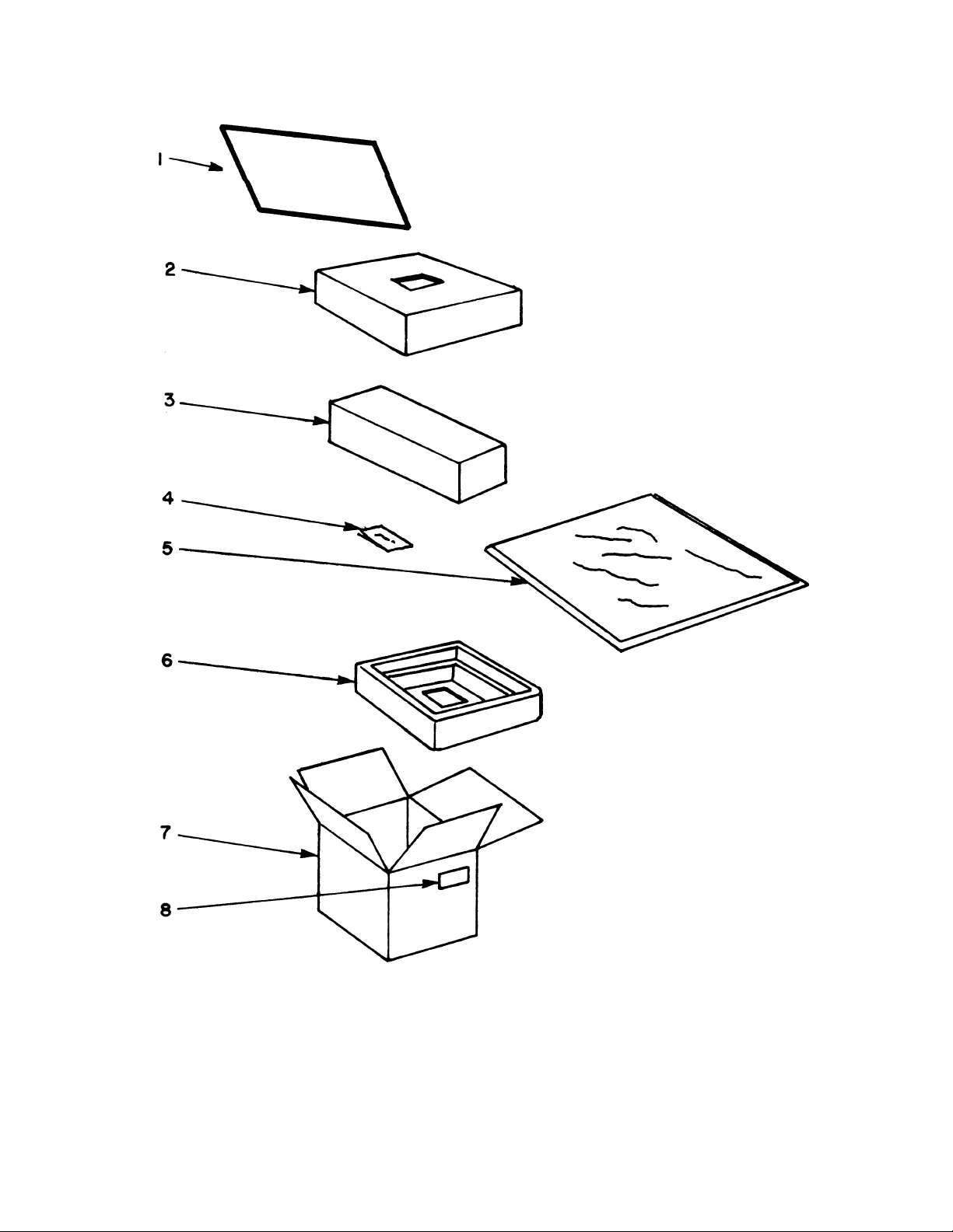
Refer to Figure 2-1 as a guide in performing the following unpacking procedures:
a. Open top of the fiberboard box (7, Figure 2-1) and remove the polystyrene top piece (2) from box.
b. Remove barrier bag (5) from the box.
c. Remove the BDR assembly (3) from barrier bag (5).
d.
Remove packing slip (8) from the plastic envelope on the fiberboard box and check to ensure that all
items listed on the packing slip were received.
2-1
TO 31R2-2TRC207-1
Legend for Figure 2-1
1. Operating instructions 5. Barrier bag
2. Polystyrene top 6. Polystyrene bottom
3. BDR assembly 7. Fiberboard box
4. Desiccant bag 8. Packing slip
Figure 2-1. Packaging Diagram for the BDR
2-2

e. Store all packing materials (except the desiccant bag) in shipping container and store shipping container
for re-use. New desiccant material must be used when repacking.
f. Inspect top and bottom, both sides, and front and rear panels of equipment for dents, scratches or any
visually identifiable damage.
g. Inspect controls and indicators on control panel for missing, broken or cracked knobs or levers and note
any discrepancies on Receiving Report, DD Form 1348-1. Report any discrepancies in accordance with
standard internal receiving procedures.
2-4 HOUSING.
If necessary to store the BDR for any period of time before installation, proceed as follows:
a. Clean the BDR before placing in storage, if necessary. Refer to paragraph 6-3.3.2.
b. Disconnect antennas and accessories before placing the BDR in storage.
c. Remove receiver-transmitters from the BDR assembly before placing in storage.
d. Remove batteries.
NOTE
TO 31R2-2TRC207-1
The temperature of the storage area must be within the range -51°C (-60°F) to +68°C (155°F).
2-5 RECEIVING DATA.
Table 2-1 identifies the contents of the shipping container.
Table 2-1. BDR Packaging
Dimensions (in)
Box Description
1 BDR 34.625 68 33.75 195
WDL
Weight
(lb.)
2-6 MATERIAL HANDLING.
The weight of the equipment is such that a minimum of two persons are required to lift the (unpacked) equipment.
2-3

TO 31R2-2TRC207-1
y
t
y
f
2-7 CABLES.
Table 2-2 lists all BDR interconnecting cables.
Table 2-2. BDR Interconnecting Cables
Cable
Designation
W1 4500117-501 Cable Assembly, BDR Power Connects power supply DC output to bi-
W2 SS-3500292-504 Cable Assembly, Coaxial, RF Connects diplexer receiver (RX) output
W3 SS-3500292-505 Cable Assembly, Coaxial, RF Connects diplexer transmitter (TX)
W4 SS-3500292-503 Cable Assembly, Coaxial, RF Connects diplexer antenna (ANT) outpu
W5 SS-3500279-502 Strap Assembly, Ground Connects bi-directional repeater assembl
W6 SS-3500279-503 Strap Assembly, Ground Connects diplexer to external ground
W7 SS-3500279-504 Strap Assembly, Ground Connects power supply to external
W9 SS-4500107-501 Cable Assembly, Power Supply, 120
W9 SS-4500108-501 Cable Assembly, Power Supply, 240
W9 SS-4500109-501 Cable Assembly, Power Supply, DC Connects BDR to 10-32 VDC
Cable Part No. Description Use
directional repeater
to bi-directional repeater assembly
output to bi-directional repeater assembl
to RF IN of power supply
to external ground
ground
Connects BDR to 120 VAC
VAC Input
Connects BDR to 240 VAC
VAC Input
W10 SS-1600315-1 Cable Assembly, Coaxial, Antenna Connects antenna to antenna connector o
bi-directional repeater power supply
2-8 BUILDING AND OTHER SUPPORTING STRUCTURES
Not Applicable.
2-4

TO 31R2-2TRC207-1
Section II. INSTALLATION PROCEDURES
2-9 SPECIAL TOOLS AND EQUIPMENT REQUIRED FOR FIELD
INSTALLATION.
No special tools or equipment are needed for installation and initial setup of the BDR.
2-10 INSTALLATION SEQUENCE
(See FO-1.) Perform the following procedure to install the BDR. Cables required for installation are listed in Table 2-2.
FO-1 illustrates the required cable connections.
2-10.1 Antenna/Mast Installation
(Refer to Figure 2-2.) Install the antenna mast and selected antenna as follows:
WARNING
Ensure proper use of safety tools (work gloves and hard hat) during assembly and disassembly
of antenna and mast.
NOTE
The BDR assembly is shipped from the factory configured for 30-88 MHz operation, with the
appropriate receiver-transmitters and diplexer. If using a different configuration, substitute the
appropriate antenna, receiver-transmitters, and diplexer. Refer to Chapter 6 for antenna and
diplexer removal and replacement. Refer to TO 31R2-2PRC139-1 for changing receivertransmitter configuration.
NOTE
The assembled antenna base section/antenna adapter will fit in the mast transit bag (3) so that step
a may be carried out prior to field deployment, if required. When erecting the antennas in high
winds, ensure that a minimum of three personnel are used.
a. Bolt the antenna base section (1, Figure 2-2) to the antenna adapter (2) and connect the antenna ground
strap to its terminal.
b. Select an unobstructed site. Under windy conditions mast raising is made easier if the mast is laid out
on the ground with the base of the mast pointed into wind.
Figure 2-2. Antenna Mast/Antenna Installation (Sheet 1 of 6)
2-5
TO 31R2-2TRC207-1
c. Remove both mast sections from the transit bag (3). Note that the socketed end is the lower end of each
section. Place the tubes in line along the ground. Assemble the two tube sections together.
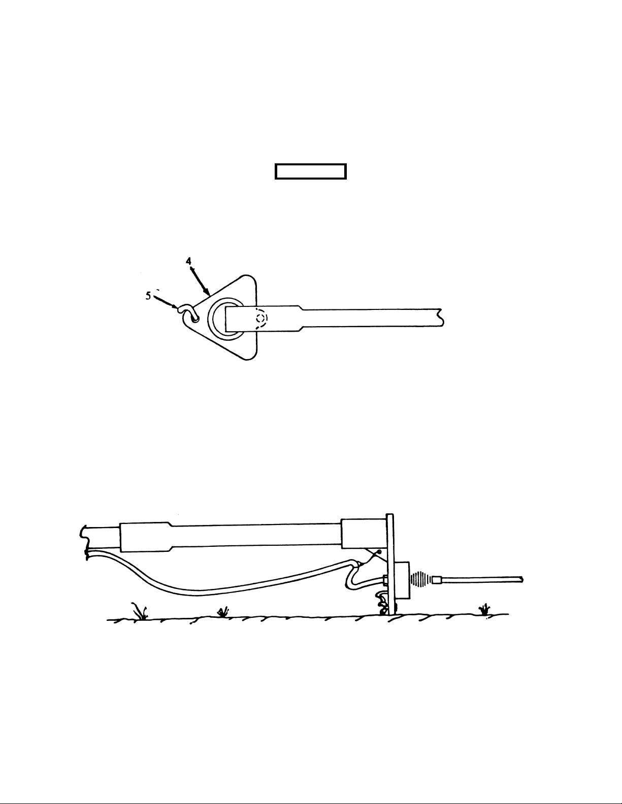
d. Remove the base plate (4), two ground spikes (5), and hammer from the transit bag. Place the base
plate at the mast base, arrowhead style, so that the socketed lower end of the mast will engage in the
heel. Secure the base plate by driving the two ground spikes through the holes.
Before using the hammer, ensure a wedge is placed in the top of the hammer so that the hammer
head does not come loose, thereby endangering personnel.
WARNING
Figure 2-3. Antenna Mast/Antenna Installation (Sheet 2 of 6)
e. Place the antenna/adapter assembly on the top mast section. Ensure the adapter is fully seated on the
mast section. Connect the top coaxial cable connector to the antenna and attach cable strain relief to
hole in web of adapter. Rest flat edge of adapter on ground to provide convenient access to guy rope
attachment points. Unwind cable along length of mast and secure to mast at centers of each section.
Secure using cable clamps.
Figure 2-4. Antenna Mast/Antenna Installation (Sheet 3 of 6)
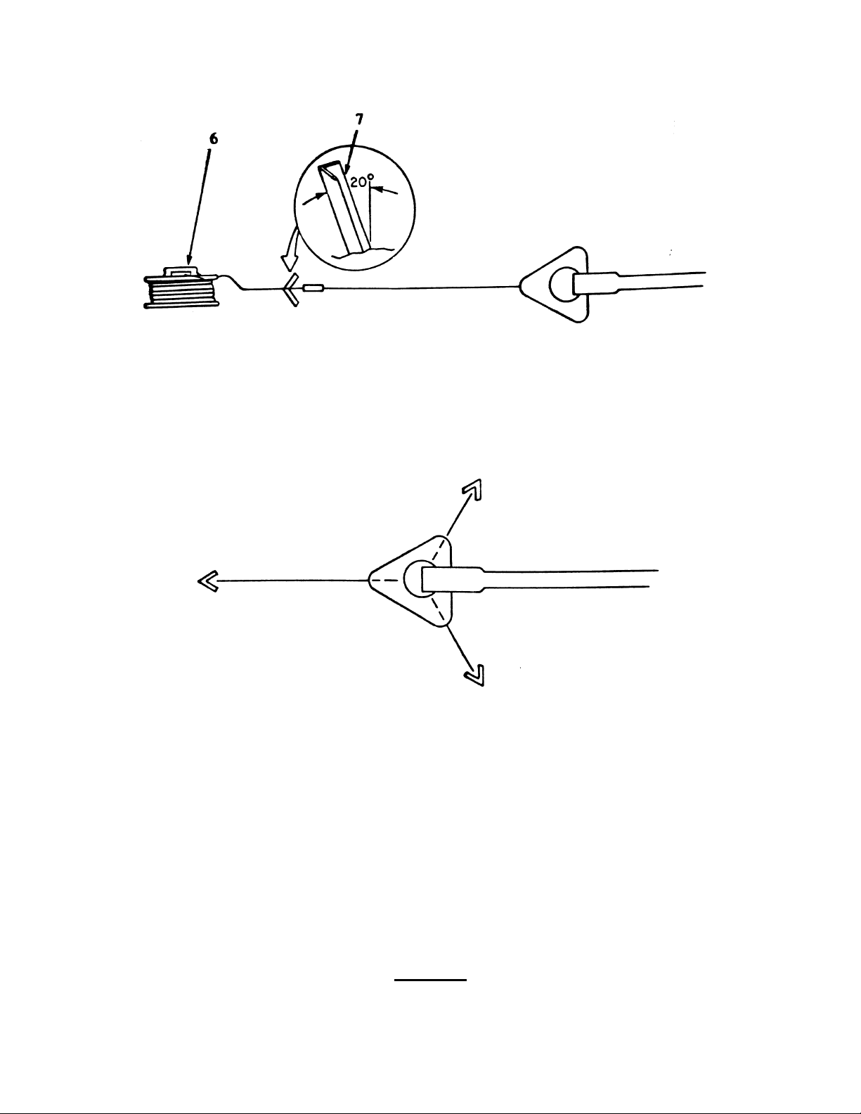
f. Remove three guy rope assemblies (6) and three ground anchors (7) from the transit bag. Disconnect
the first (fixed) snap hook off the winder and temporarily connect it to the base plate. Carrying the
hammer and one of the ground anchors, walk away in the exact opposite direction to the mast (i.e., in
the direction that the arrow head is pointing) unwinding the guy rope as you go, until the ground anchor
radius marker is reached. Drive in the ground anchor at this point ensuring that it leans away from the
mast (approximately 20
o
from vertical).
2-6
TO 31R2-2TRC207-1
Figure 2-5. Antenna Mast/Antenna Installation (Sheet 4 of 6)
g. Using the same guy rope as a radius guide, walk across to the approximate location of the second
ground anchor. Establish the required 120E from the first ground anchor by using the triangular shape
of the base plate as a reference. Drive in a second ground anchor at this point.
Figure 2-6. Antenna Mast/Antenna Installation (Sheet 5 of 6)
h. Repeat step g for the third ground anchor.
i. Disconnect the guy rope used for a radius marker. Attach the fixed (upper) snap hook to the attachment
point on the antenna adapter. Attach the running hook at the lower end to ground anchor 2. Note that
the winder remains attached to the lower ends of the guy rope to prevent accidental loss.
j. Take a second guy rope. Attach the fixed (upper) snap hook to the antenna adapter attachment point.
Attach the running hook at the lower end to ground anchor 3.
k. Attach the upper snap hook of the third guy rope to the adapter attachment point. Unwind the rope
along the length of the mast toward the ground anchor 1, but do not attempt to attach the lower end yet.
Ensure that guy ropes will not snag the coaxial cable when the mast is raised.
CAUTION
The adapter and antenna can lift off the mast while the mast is being raised if the adapter is not
completely seated on the top mast section.
2-7
TO 31R2-2TRC207-1
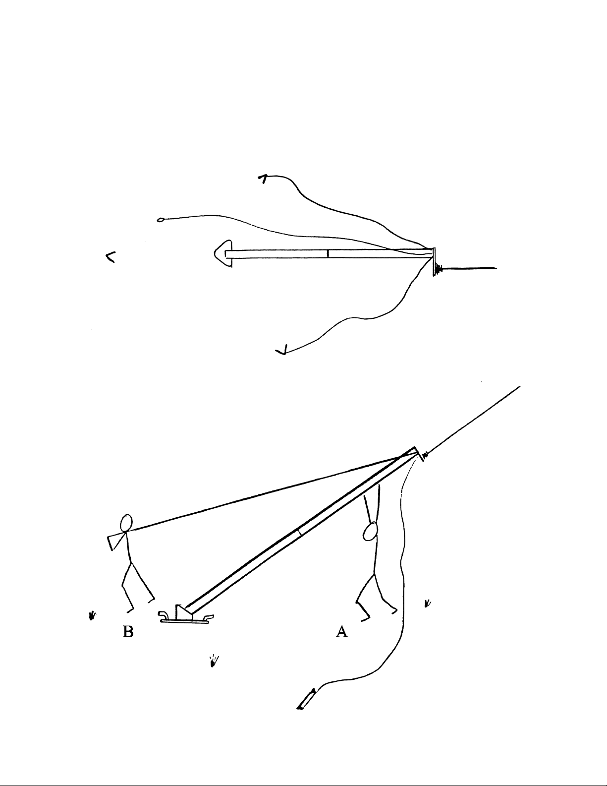
l. Ensure foot of mast is securely located in the base plate heel. While person A pushes up mast head Iwo
Jima style, person B pulls on guy ropes to raise mast to vertical. Person A should progressively walk
towards bottom of mast as it is raised and should hold mast steady as it reaches the vertical. Person B
attaches free guy ropes to ground anchor 1 and tightens all ropes.
m. Connect the coaxial antenna cable (SS-1600315-1) to the connector at the back of the power supply.
Refer to FO-1.
2-8
Figure 2-7. Antenna Mast/Antenna Installation (Sheet 6 of 6)

TO 31R2-2TRC207-1
2-10.2 Lithium Battery Installation.
(Optional) (This procedure is also applicable to the Type BB-590/U NiCd batteries.) The battery enclosure has
connectors for four type BA-5590/U Lithium batteries. The connectors are mounted in the bottom of the enclosure. To
install the batteries, first turn the BDR off using the switch on the top of the power supply enclosure. Open the battery
enclosure. Taking each battery, in turn, turn the battery so that the connector is facing down, align the connector on the
battery with the connector in the bottom of the enclosure, and push down on the battery until seated.
To power the BDR from the installed batteries, set the power supply POWER switch to DC, and the DC SEL switch to
INT. Ensure that both circuit breakers on the side of the power supply are ON. The repeater is capable of full operation
with either three or four batteries installed. For battery operation, use of the 2 WATT mode will greatly prolong battery
life.
2-10.3 Ground Rod Installation.
The ground rod assembly consists of a 3 foot long ground rod and an attached 10 foot grounding strap. The grounding
strap ends in a spade lug that is connected to a ground screw on the BDR assembly frame next to the power supply
assembly. (See Figure 1-1 for illustration of grounding strap connection.)
To install, place the BDR in its selected operating location. Locate the ground lug on the frame and select a spot for the
ground rod within a 10 foot arc of the ground screw. Drive the ground rod into the ground with a sledge hammer until
the grounding strap clamp is level with the ground. Remove the wing nut and washer from the ground screw, place the
spade lug over the screw, and reattach the washer and wing nut.
2-10.4 External Power Supply.
To connect the BDR to an external power supply, select the appropriate power supply cable to match the external source
(110/220 VAC, 240 VAC, or 10-32 VDC). Connect the power supply cable to the POWER IN connector on the power
supply and connect to the power source. Set the power supply POWER switch and DC SEL switch as indicated in Table
2-3.
NOTE
When using external DC power, use as large a DC voltage power source as possible (e.g., a 28 volt
battery rather than two 12 volt batteries). The BDR DC power supply operates more efficiently with
larger DC voltages.
Table 2-3. External Power Supply Switch Settings
POWER SOURCE POWER DC SEL
110/220 VAC AC N/A
240 VAC AC N/A
10-32 VDC DC EXT
2-10.5 Diplexer Installation
Refer to paragraph 6-5.1.6.
2-10.6 Receiver-Transmitter Transceiver Module Installation
Refer to TO 31R2-2PRC139-1.
2-9/(2-10 blank)


TO 31R2-2TRC207-1
CHAPTER 3 PREPARATION FOR USE AND RESHIPMENT
3-1 INTRODUCTION.
This chapter is divided into two sections. Section I. Preparation For Use provides post-installation operational checks
that must be performed prior to operating the BDR. Section II. Preparation For Reshipment contains procedures for
reshipment of the unit.
Section I. PREPARATION FOR USE
3-2 INSPECTION.
If the BDR has not been inspected as part of the installation process, or if the equipment has not been used recently, check
to ensure that all cable connections are tight and no damage is visible on the exterior of the BDR.
3-3 POST-INSTALLATION CHECKOUT.
3-3.1 Preliminary
Before performing the post-installation checkout procedures of paragraph 3-3.3, perform the following preliminary
procedures.
NOTE
The receive and transmit frequencies programmed into the receiver-transmitters must be separated
by at least 4 MHz or 3 percent of the lower frequency, whichever is greater. Similarly, the
frequencies on the two nets for bi-directional operation must have similar separations. If the
minimum frequency separation is not used, the BDR will not operate properly. See paragraph 4-3
for additional data.
NOTE
For all modes of operation, the receive and transmit frequencies on the channel in use on each
radio must be the same (simplex operation).
a. Ensure that both receiver-transmitters (SS-4100807-512) have been programmed with the correct
receive and transmit frequencies and CTCSS tones. (TO 31R2-2PRC139-1 describes procedures for
programming all programmable parameters.) Use of CTCSS tones is recommended for non-secure
operation. ATONES=NONE@ should be used for secure operation.
b. Ensure that the channel select switch on each radio is set to the correct channel, the mode switch is set
to CLR, and the SCAN switch is turned off. On/Off/Volume control setting is ignored.
NOTE
Other programmable parameters (RF power, data rate, etc.) may be set to any value.
NOTE
Be sure to align the receiver-transmitters so that the orientation of the control knobs and
connectors corresponds to the markings on the sleeve door. The receiver-transmitters cannot be
inserted in the bi-directional repeater with the battery attached. The CCI receiver-transmitter
(RT-1696/U (C)) cannot be inserted into the BDR.
3-1

TO 31R2-2TRC207-1
c. Insert the receiver-transmitter (SS-4100807-512) for the (primary) transmit frequency into the right
sleeve (marked "B")of the bi-directional repeater, with the side connector facing up (refer to Figure 1-
1). Turn the cam above the receiver-transmitter clockwise until it locks (1/4 turn).
d. Similarly, insert the receiver-transmitter for the (primary) receive frequency into the left sleeve (marked
"A") of the bi-directional repeater and lock it into place.
3-3.2 Alignment and Adjustment.
The BDR is aligned and adjusted for normal operation at the factory/depot. No other alignments or adjustments are
authorized or required. The diplexer will require retuning as described in paragraph 4-3 whenever the transmit or receive
frequencies are changed.
3-3.3 Post-Installation Checkout Procedures
After completion of installation, perform the following checkout procedures.
3-3.3.1 Power-Up Check.
Perform the power-up check as follows:
a. Ensure that both receiver-transmitters are programmed with the proper type squelch settings to receive
the desired modulation format (carrier squelch (ATONES=OFF@) or CTCSS tones) (since both are
capable of receiving signals).
b. Place the BDR MODE SELECT switch (6, Figure 4-1) in one of the RETRANS mode positions (either
BDR or TR operation.)
c. Place the BDR POWER switch (8, Figure 4-1) in the 2WATT or 10WATT position.
d. Place the power supply AC/DC POWER switch (1, Figure 4-2) in either AC or DC position, depending
on source of power. If DC is selected, the DC SEL switch must be set for internal (INT) or external
(EXT) power source, as appropriate. Ensure that both circuit breakers (1 and 2, Figure 4-3) are
switched ON.
e. Ensure that the green POWER LED is illuminated when the DISPLAY switch is ON. This indicates
that the unit is receiving power from the power supply.
3-3.3.2 Operational Check.
Perform the operational checkout included in paragraph 6-2 to verify that the major components of the BDR are
functioning properly.
3-3.3.3 Equipment Shutdown.
Shut down the BDR as follows:
a. Set the power supply POWER switch to OFF.
b. Ensure that the POWER LED is not illuminated (with the display switch on).
Section II. PREPARATION FOR RESHIPMENT
3-4 PREPARING UNIT FOR RESHIPMENT
Prepare the BDR for reshipment as follows:
a. Disconnect all external accessories, antennas, and cables.
b. Remove the receiver-transmitters prior to shipment.
c.
3-2
Remove batteries (if installed).

TO 31R2-2TRC207-1
3-5 PACKING.
Pack the BDR in the recommended packages illustrated in Figure 2-1. Use original packing materials if available.
3-6 HANDLING AND STORAGE.
Place electronic assemblies in individual containers. This will prevent damage during handling and storage. If a common
container is used, use suitable barrier material between electronic assemblies. Sufficient packing must be used to prevent
shifting of electronic assemblies within the container. Package the equipment in accordance with MIL-STD-2073-1A/2B.
Marking for reshipment and storage shall be in accordance with MIL-STD-129J.
CAUTION
Never apply pressure sensitive tape directly to connectors. This could damage connector pins.
3-6.1 Protective Measures for Electrical Connectors.
Protect all unmated connectors that are exposed to physical or environmental damage by covering with supplied protective
caps.
3-6.2 Preparation for Shipment and Storage.
Before preparing the equipment for shipment or storage, ensure that the receiver-transmitters, batteries, and any other
accessories have been removed from the bi-directional repeater.
CAUTION
Package all electrostatic discharge (ESD) sensitive assemblies in ESD bags before shipping or
storing.
For shipment to another facility or long-term storage, package the unit as shown in Figure 2-1. Regardless of the
electronic assembly design, fit all protruding parts with packing spacers, wrap the complete assembly with plastic or place
in a plastic air-lock bag. Wrap with a protective cellulose, foam, or similar material. Wrap assemblies that contain
electrostatic discharge sensitive (ESDS) parts in static protective materials.
3-6.3 Handling.
Following are general handling instructions which should be followed when handling the equipment.
WARNING
Before performing removal/replacement procedures, make sure power is removed from the unit
by disconnecting from power source. Failure to do so could result in personal injury or equipment
damage.
CAUTION
Rough handling may cause unnecessary damage to electronic assemblies.
CAUTION
Electronic assemblies containing solid-state devices are susceptible to damage from static
electrical discharges. Wear protective clothing and grounded wrist straps.
3-3

TO 31R2-2TRC207-1
CAUTION
Forcing any tilted or cocked electronic assembly into position may result in bent or broken pins.
Be very careful when removing or inserting an assembly into the equipment. If it is a plug-in CCA, be sure the guide pins
are properly aligned before pressing the assembly in place. If the CCA tilts while being inserted, do not continue to press
into position; straighten it, then apply even pressure to avoid tilting.
CAUTION
When repairing an electronic assembly, be careful that the tool employed does not inadvertently
press against leads, pins, or other parts that are easily bent.
CAUTION
Because of the miniaturization of parts for electronic assembly construction, the leads, connectors,
and pins have been stiffened to make them more rugged. As a result, such parts are brittle and
will break easily if bent too often or pulled on too hard. When handling an assembly that has been
removed from its chassis, be careful not to press against the leads and pins. When removing an
assembly, be sure to pull it straight out from the equipment. Do not cock, twist, pry, or carelessly
jerk an electronic assembly to remove it from the mounting or connector.
CAUTION
ELECTROSTATIC DISCHARGE
The bi-directional repeater contains components that are susceptible to damage by static electrical
charges. Disassembly of the bi-directional repeater should only be done at a properly grounded
work station.
3-4

TO 31R2-2TRC207-1
CHAPTER 4 OPERATION
Section I. CONTROLS AND INDICATORS
4-1 INTRODUCTION
This section describes and illustrates indicators, controls, switches, and connectors of the bi-directional repeater.
4-2 CONTROLS AND INDICATORS.
The following paragraphs describe and illustrate all operational controls and indicators of the bi-directional repeater.
4-2.1 Indicators, Controls, and Switches.
All indicators, controls, and switches for the bi-directional repeater are illustrated in Figure 4-1 and described in Table
4-1.
4-2.2 Power Supply Switches and Connectors.
The bi-directional repeater power switches and top connectors are located on the power supply assembly. The power
switches are illustrated in Figure 4-2 and described in Table 4-2.
4-2.3 Connectors.
External side connectors for the power supply are illustrated in Figure 4-3 and described in Table 4-3. External
connectors for the repeater unit are illustrated in Figure 4-4 and described in Table 4-4.
4-2.4 Diplexer Control
All diplexer controls for the bi-directional repeater are illustrated in Figure 4-5 and described in Table 4-5.
Figure 4-1. Location of Bi-Directional Repeater Indicators, Controls, and Switches
4-1

TO 31R2-2TRC207-1
Table 4-1. Description of Indicators, Controls and Switches
Fig & Index Number Control/Switch Function
STATUS:
4-1-1 DISPLAY Switch (two-
position rotary switch)
4-1-2 FAULT LED (red) When illuminated, indicates 1) RF power amplifier internal
4-1-3 RCV (Receive) LED
(amber)
4-1-4 XMT (Transmit) LED
(amber)
4-1-5 POWER LED (green) When illuminated, indicates power is applied to the bi-
4-1-6 MODE SELECT Switch
(six-position rotary switch)
Controls whether the front panel indicators are operational
(ON position) or not operational (OFF position) (The
DISPLAY switch should be kept in OFF position to
conserve battery life following initial power-up and
function check.)
temperature is excessive (greater than 90E C), 2) RF path
fault (diplexer or BDR is cabled incorrectly, diplexer is
tuned incorrectly, or frequency spacing is less than
recommended minimum), or 3) no or faulty radio in
Radio A sleeve.
When illuminated in the RETRANS and COMMS modes,
indicates reception of a transmission.
When illuminated in the RETRANS and COMMS modes,
indicates retransmission of a reception. Illuminates also
in the TUNE A or TUNE B mode to indicate that the A
or B receiver-transmitter is active.
directional repeater.
Allows selection of the bi-directional repeater operating
mode as follows:
RETRANS - Selects bi-directional repeater (BDR)
operation (receive or transmit on either radio) or single
direction tactical repeater (TR) operation (receive on
one radio, transmit on the other). Unencrypted through
traffic can be monitored via local accessory. Local
transmit capability is disabled.
COMMS - Selects Terminal A or Terminal B modes
(broadcast capability through radio A or radio B).
Unencrypted traffic reception is available through either
radio. Local transmit is available through the selected
radio.
TUNE A - Allows the "A" receiver-transmitter path of
the diplexer to be tuned. All other repeater functions are
disabled.
TUNE B - Allows the "B" receiver-transmitter path of
the diplexer to be tuned. All other repeater functions are
disabled.
4-1-7 POWER Select Switch Selects an output power level of 2 watts or 10 watts.
4-1-8 VOLUME Control Volume control for attached audio accessory.
4-1-9 Audio Connector Standard 6-pin connector for audio accessory.
4-2

TO 31R2-2TRC207-1
Figure 4-2. Location of Power Supply Switches (Power Supply Top View)
Table 4-2. Description of Power Supply Switches
Fig & Index Number Switch Function
4-2-1 DC SEL (INT/EXT) Select
switch (two-position toggle
switch)
4-2-2 AC/DC POWER (DC/OFF/
AC) switch (three-position
toggle switch)
4-2-3 POWER OUTPUT Connector for power output cable to bi-directional repeater
Allows selecting either the internal battery power source or
an external DC source when the AC/DC POWER switch is
in the DC position.
Allows the operator to turn the bi-directional repeater on
and off, and select either an AC or DC power source.
unit
4-3

TO 31R2-2TRC207-1
Figure 4-3. Location of Power Supply Connectors (Power Supply Side View)
Both the DC and AC Circuit Breakers (4-3-1 and 4-3-2) MUST be switched ON for AC operation
NOTE
Table 4-3. Description of Power Supply Connectors
Fig & Index Number Connectors Function
4-3-1 DC Power Circuit Breaker
15 Amp
4-3-2 AC Power Circuit Breaker
1 Amp
4-3-3 External Power Input
Connector
4-3-4 Antenna Out Coaxial cable to antenna.
4-3-5 RF In Coaxial cable to diplexer.
In-line circuit breaker for DC power (Input and output)
In-line circuit breaker for AC input power
External power supply input.
4-4

TO 31R2-2TRC207-1
Figure 4-4. Location of Bi-Directional Repeater Unit Connectors
Table 4-4. Description of Repeater Unit Connectors
Fig & Index Number Connectors Function
4-4-1 Radio A/RX (Receive)
Connector J3
4-4-2 POWER Connector J1 Connects repeater to repeater power supply unit.
4-4-3 GND (Ground) Stud Provides chassis ground point; connects repeater unit to
4-4-4 Radio B/TX (Transmit)
Connector J2
Input from diplexer receive connector to repeater.
frame system ground.
Input from diplexer transmit connector to repeater.
4-5

TO 31R2-2TRC207-1
Figure 4-5. Location of Bi-Directional Repeater Diplexer Controls
Table 4-5. Description of Diplexer Controls
Fig & Index Number Control/Switch Function
4-5-1 Tuning Meter Measures relative strength of transmit or receive signals
during diplexer tuning.
4-5-2 SENS Control The SENS control is only active when the TUNE switch is
held depressed. The SENS control adjusts the meter
sensitivity for tuning purposes. Maximum clockwise
position allows the meter to respond to low RF inputs.
4-5-3 RCV (Receive) Control
Tuning Knob and
Frequency Meter)
4-5-4 XMT (Transmit) Control
(Tuning Knob and
Frequency Meter)
4-5-5 TUNE Switch When held depressed, allows diplexer meter to respond to
The RCV control adjusts the bandpass frequencies of the
diplexer for the RX receiver-transmitter (HHR A).
Movement of the RCV tuning knob causes the RCV
frequency meter movement. The tuning knob has a locking
ring to prevent inadvertent movement.
The XMT control adjusts the bandpass frequencies of the
diplexer for the TX receiver-transmitter (HHR B).
Movement of the XMT tuning knob causes the XMT
frequency meter movement. The tuning knob has a locking
ring to prevent inadvertent movement.
RF input from the A or B receiver-transmitter. The TUNE
switch is used in conjunction with the SENS control to
accomplish tuning.
4-6

TO 31R2-2TRC207-1
Section II. OPERATING INSTRUCTIONS
NOTE
Be aware that while performing the initial power-up and diplexer tuning procedures, the bidirectional repeater will radiate RF energy that can cause frequency interference. Do not perform
this procedure before the frequency use authorization is obtained and in effect.
4-3 OPERATING MODES AND FREQUENCY RECOMMENDATIONS
This paragraph describes the different modes of operation available with the BDR and provides recommendations for
frequency selection to obtain optimum results in each mode.
4-3.1 Operating Modes
There are four different BDR operating modes, described in the following paragraphs.
4-3.1.1 Tactical Repeater Mode.
In this mode, the BDR operates in the same fashion as the basic Tactical Repeater (AN/TRC-199). It can provide one-way
extended range linking of one simplex communications net (in which the radios are set to transmit and receive on the same
frequency) with another simplex net (see Table 4-6), or limited two-way extended range of a half-duplex net (in which
the radios transmit and receive on different frequencies) (see Table 4-7).
4-3.1.2 Standalone Bi-directional Repeater.
One BDR can provide full two-way extended range to a simplex communications net (see Table 4-8). It can be used to
link two simplex nets such that they operate as one communications net, even though the radios in the two nets are
operating on different frequencies.
4-3.1.3 Tandemed Bi-directional Repeater.
Two or three BDRs can be set up in series (tandemed) to provide two-way communications over a greatly extended range
(see Table 4-9). When multiple repeaters are used, user radios may operate on any of the frequencies used in the series
(that are within line-of-sight range). For example, users in between two BDRs are able to communicate to users at either
or both ends of the chain, depending on the frequency selected.
4-3.1.4 COMMS Mode.
In COMMS mode, the BDR can be used to transmit and receive (unencrypted) radio traffic and to monitor (unencrypted)
through traffic on the communications net. This can be done using either Radio A or B.
4-3.2 Frequency Recommendations
General frequency recommendations are shown in the following tables. The basic communications set-up is a Base
Station communicating through a BDR to one or more remote handheld radios (HHRs). The frequencies shown in each
table (F
requirement in determining specific frequencies to be used is that the radio A frequency and the radio B frequency must
be separated by at least 4 MHz or 3 percent of the carrier frequency, whichever is greater. Examples of the required
separation are:
, F2, F3) are frequencies within one band that satisfy the separation requirement described below. A critical
1
Frequency A: 30 MHz Frequency B: at least 34 MHz
Frequency A: 88 MHz Frequency B: no more than 84 MHz
Frequency A: 136 MHz Frequency B: at least 140 MHz
Frequency A: 174 MHz Frequency B: no more than 168.75 MHz
Frequency A: 403 MHz Frequency B: at least 415.1 MHz
Frequency A: 470 MHz Frequency B: no more than 455.9 MHz
4-7

TO 31R2-2TRC207-1
4-3.2.1 Tactical Repeater Mode.
Table 4-6. TR Simplex Mode Recommended Frequencies
The Mode Select switch should be set to the bi-directional RETRANS position.
MODE EQUIPMENT TRANSMIT FREQUENCY RECEIVE FREQUENCY
Simplex Base Station F
Simplex BDR, Radio A F
Simplex BDR, Radio B F
Simplex HHR F
Table 4-7. TR Half-Duplex Mode Recommended Frequencies
The Mode Select switch should be set to the uni-directional RETRANS position.
MODE EQUIPMENT TRANSMIT FREQUENCY RECEIVE FREQUENCY
Half-Duplex Base Station F
Half-Duplex BDR, Radio A F
Half-Duplex BDR, Radio B F
Half-Duplex HHR F
4-3.2.2 Standalone Bi-Directional Repeater.
Table 4-8. Single BDR Recommended Frequencies
The Mode Select switch should be set to the bi-directional RETRANS position.
1
1
2
2
1
1
2
1
F
1
F
1
F
2
F
2
F
2
F
1
F
2
F
2
4-8
EQUIPMENT TRANSMIT FREQUENCY RECEIVE FREQUENCY
Base Station F
BDR, Radio A F
BDR, Radio B F
HHR F
1
1
2
2
F
1
F
1
F
2
F
2

4-3.2.3 Tandemed Bi-Directional Repeater.
HHRs can be programmed with two or more channels to permit the user to access another repeater
when one is blocked from view.
Table 4-9. Tandemed BDR Recommended Frequencies
The Mode Select switch should be set to the bi-directional RETRANS position.
EQUIPMENT TRANSMIT FREQUENCY RECEIVE FREQUENCY
TO 31R2-2TRC207-1
NOTE
Base Station F
HHR Region 1 F
BDR #1, Radio A F
BDR #1, Radio B F
HHR Region 2 F
BDR #2, Radio A F
BDR #2, Radio B F
HHR Region 3 F
BDR #3, Radio A F
BDR #3, Radio B F
HHR Region 4 F
1
1
1
2
2
2
3
3
3
4
4
F
1
F
1
F
1
F
2
F
2
F
2
F
3
F
3
F
3
F
4
F
4
4-3.2.4 COMMS Mode.
Any of the above frequency set-ups can be used in COMMS mode.
4-3.2.5 Operational Techniques.
In addition to frequency separation, there are other considerations that should be made when programming the radios for
use:
a. When operating predominantly in the CLEAR mode, use CTCSS tones to reduce unwanted re-
transmitting. (Only RX tones are effective in the BDR, not TX tones.)
b. When operating predominantly in the SECURE mode, program the BDR radios for ATONES=OFF@
to speed re-transmission turnaround time.
c. When operating in the SECURE mode, wait approximately 0.5 sec. at the end of a message before
replying.
4-3.2.6 Cross-Banding.
The BDR can be used with different frequency bands on Radios A and B (e.g., Radio A in 136-174 MHz band and Radio
B in 30-88 MHz band).
4-3.2.6.1 Additional Equipment Requirements.
When using two frequency bands, separate antennas, antenna cables, antenna masts, and diplexers are required for each
band used. As noted in Chapter 1, the second antenna mast and antenna cable are not provided with the system. These
items can be borrowed from other Scope Shield systems, e.g., Tactical Repeater/BDR or Base Station, or may be
purchased separately.
4-3.2.6.2 Set-up.
If the 30-88 MHz band is used, the 30-88 MHz band radio should be inserted in the Radio B sleeve and the B/TX
connector (J2) on the BDR unit must be connected to the RF IN connector on the power supply assembly using cable W3.
The antenna cable for Radio B is connected to the ANTENNA connector on the power supply assembly and the antenna
cable for Radio A is connected directly to the A/RX connector (J3) on the BDR assembly. Figure 4-6 shows the initial
(standard) set-up for normal operation. Figure 4-7 shows how the standard set-up is changed for cross-banding operation.
4-9

TO 31R2-2TRC207-1
Figure 4-6. Standard BDR Cabling Set-up
4-10
Figure 4-7. BDR Cross-Banding Cabling Set-up

TO 31R2-2TRC207-1
NOTE
The transmit power for RADIO A will always be at peak power regardless of the front panel
POWER setting because the routing for RADIO A does not pass through the Power Supply unit,
which senses the transmit power and provides gain control back to the power amplifier. Thus,
the POWER setting on the front panel only controls the transmit power of RADIO B.
4-3.2.6.3 Precautions for Cross-Banding.
The tripping of circuit breakers and excessive heating could occur if the 30-88 MHz band is not connected as shown in
Figure 4-7 , ensuring that the 30-88 MHz band RF path is connected through the Power Supply unit. Avoid using
frequencies that are harmonically related, integral multiples of each other, as this could cause the system to lock up by
receiving internally generated signals. For example, avoid using combinations such as 76.55 MHz and 153.10 MHz or
150.2 MHz and 450.6 MHz. Do not use the 150 Hz RX and TX tone in this configuration. If RX and TX tones are used
the same tone must be used in all radios in both bands. A slight degradation in audio level will occur when the system
is configured for cross-banding in the 30-88 MHz band, which could limit the tandem ability in the unencrypted mode.
Either side, TX or RX, of the diplexer can be used but the ANT port of the diplexer must be connected to an antenna or
the RF IN port of the Power Supply unit. Even though one side of each diplexer is unused, the TX and RX frequency
spacing of each diplexer must have the minimum spacing as stated in paragraph 4-3.2. It is important to check that
diplexer tuning is adequate by using the TUNE modes (see paragraph 4-4) and to verify proper operation by establishing
voice communications using both COMMS modes with radios.
4-4 INITIAL POWER-UP AND DIPLEXER TUNING PROCEDURES
Perform the following procedure to power-up the bi-directional repeater and tune the diplexer.
a. Ensure that the RF cables are properly connected to TX connector J2 (4, Figure 4-4) and RX connector
J3 (1, Figure 4-4). Ensure that the proper antenna and diplexer are installed. Ensure that both receivertransmitters are programmed in a simplex configuration (same receive and transmit frequencies) for
each channel being used. It is recommended that CTCSS tones (see TO 31R2-2PRC139-1) be used
for repeater operations in the non-secure mode, particularly for tandemed BDRs. All radios in the
intended communications net must be programmed with the same tone. Tones should be set to "OFF"
for secure operation.
b. Ensure that the bi-directional repeater has been installed as described in Chapter 2. Place the MODE
SELECT switch (6, Figure 4-1) in one of the COMMS positions. Place the POWER switch (7, Figure
4-1) in the 2 WATT position. Place the AC/DC POWER switch (2, Figure 4-2) in the DC or AC
position, as applicable, and the DISPLAY switch (1, Figure 4-1) in ON position. If DC power is
selected, place the DC SEL switch (1, Figure 4-2) in the EXT or INT position, as appropriate. Ensure
both circuit breakers are set to ON. Verify that the green POWER LED (5, Figure 4-1) is illuminated.
c. Using the channel select switch on the transmit receiver-transmitter (HHR B), select as the transmit
channel the same channel that is being used by the remote receiving receiver-transmitter.
d. Using the channel select switch on the receive receiver-transmitter (HHR A), select as the receive
channel the same channel that is being used by the remote transmitting receiver-transmitter.
e. Set the diplexer SENS control (2, Figure 4-5) fully clockwise.
f. Release locking ring on diplexer RCV tuning dial (3, Figure 4-5). Coarse tune the RCV tuning dial (3,
Figure 4-5) to the approximate receive channel frequency.
g. Release the locking ring on the XMT tuning dial. Coarse tune the XMT tuning dial (4, Figure 4-5) to
the approximate transmit channel frequency.
h. Place the bi-directional repeater MODE SELECT switch (6, Figure 4-1) in the TUNE A position.
i. Adjust the RCV tuning dial (3) with the red TUNE button (1) depressed until a peak meter indication is
noticed. If the meter produces 100% deflection, turn SENS control (2) counterclockwise until adjustment
of the RCV control yields a peak response less than 100% deflection. Tighten the locking ring on the RCV
tuning dial.
4-11

TO 31R2-2TRC207-1
j. Set the SENS control fully clockwise.
k. Place the bi-directional repeater MODE SELECT switch (6, Figure 4-1) in the TUNE B position.
l. Adjust the diplexer XMT tuning dial (4, Figure 4-5) with the red TUNE button (5) depressed until a
peak meter indication is noticed. If the meter produces 100% deflection, turn the SENS control
counterclockwise until adjustment of the XMT control yields a peak response less than 100%
deflection. Tighten the locking ring on the XMT tuning dial.
m. Set the MODE SELECT switch to either of the COMMS positions. Establish a communication link
with the corresponding remote unit (unit tuned to receive the transmit frequency of each of the
COMMS modes). The remote unit should be 20 or more feet away from the BDR (preferably at the
expected operational distance). If communication cannot be established, turn the POWER switch to
the 10 WATT position and attempt communication again.
n. Set the MODE SELECT switch to the other COMMS position and establish a communication link with
the other remote unit.
o. Set the MODE SELECT switch to the single directional (TR) or bi-directional (BDR) mode, as desired.
p. Monitor through traffic via the front panel audio connector, with both remote links set for clear
transmission. If the BDR stays keyed constantly, even with no through traffic present, connect a
frequency fill device to each radio and reprogram the squelch level to a higher setting. Alternatively,
all radios (including the remote links) can be programmed with CTCSS tones.
q. Place the DISPLAY switch (1, Figure 4-1) to the OFF position to conserve battery life.
r. Cover the BDR with the frame cover for concealment and for some protection from the elements.
After the above procedures have been successfully completed, the bi-directional repeater is in an operational mode and
can begin to relay radio traffic.
4-5 RECEIVING AND RETRANSMITTING MESSAGES
Whenever the bi-directional repeater is turned on, it is capable of receiving messages and transmitting them (relaying
them) back out. Receive and retransmit messages as follows:
a. Perform the initial power-up and diplexer tuning procedure of paragraph 4-3 to turn on the bi-
directional repeater and prepare it for operation.
b. Set the POWER switch (6, Figure 4-1) to 2WATT or 10WATT. Turn the DISPLAY switch to ON.
c. Ensure the receiver-transmitters are programmed with the proper type squelch settings to receive the
desired modulation format (carrier squelch or CTCSS tones).
d. When a carrier with the proper modulation format is received by the repeater, the RCV LED (3, Figure
4-1) and XMT LED (4) illuminate to verify proper re-transmit operation.
e.
If the receiver-transmitter is programmed for carrier squelch and the repeater receives a carrier without
CTCSS tones, with CTCSS tones, or with encryption, the RCV LED (3, Figure 4-1) illuminates to
verify proper operation. If the receiver-transmitter is programmed for a CTCSS receive tone, the RCV
LED (3, Figure 4-1) illuminates only when a carrier with the correct CTCSS tone is received. If an
encrypted message is received, the RCV LED (3, Figure 4-1) will illuminate. Encrypted messages will
be received and retransmitted even if CTCSS tones are programmed on the receive channel.
4-12

TO 31R2-2TRC207-1
4-6 COVERT OPERATIONS
LEDs on the front panel of the bi-directional repeater are disabled to allow light discipline in blackout conditions. The
frame cover is used to further conceal the BDR. Turning off the LEDs also helps to conserve battery power.
By placing the DISPLAY switch (1, Figure 4-1) in the OFF position, all
4-7 RECEIVER-TRANSMITTERS
For operating procedures for the receiver-transmitters, refer to TO 31R2-2PRC139-1. Ensure that the MODE switch on
both radios is set to CLR and the SCAN switch is OFF. Disregard operating procedures for secure mode.
4-8 EQUIPMENT SHUTDOWN
Shut down the bi-directional repeater as follows:
a. Place the AC/DC POWER switch (1, Figure 4-2) in the OFF position.
b. Verify that the BDR is off by confirming that the POWER LED is not illuminated when the DISPLAY
switch (1, Figure 4-1) is in the ON position.
c. Emergency shutdown can be accomplished by setting the power supply circuit breakers switches (1 and
2, Figure 4-3) to the FAULT/OFF position.
Section III. EMERGENCY OPERATION
4-9 EMERGENCY POWER
The bi-directional repeater can be powered directly from a battery installed in a vehicle for external power. Use the DC
power supply cable assembly (SS-4500109-501) with the positive cable lug connected to the positive battery terminal and
the negative cable lug grounded to the vehicle frame.
4-10 ELECTROMAGNETIC PULSE PROTECTION
Electromagnetic Pulse (EMP) is a pulse of broad bandwidth, high amplitude radio frequency electromagnetic energy
produced by the radiation from a nuclear burst.
4-10.1 EMP Susceptibility
EMP can deliver a power density to a radio receiver a billion times greater than the power necessary for reception. The
voltage and current surges resulting from EMP can overload most modern solid state electronic devices.
4-10.2 EMP Protective Measures
All equipment not absolutely required in primary systems should remain disconnected and stored within a sealed shelter
or other shielded enclosure for protection from EMP. At a minimum, equipment not required should be turned off. To
prevent or reduce "coupling" with the energy from EMP, wires and cables (to include output coaxial types) should be
shielded and properly grounded. Lengths of cables should be kept as short as possible. Excess lengths of cable in use
should never be left wound on a cable reel but should be pulled out in a straight line to avoid having loops in the cables.
When cables are not needed, they should not be connected to the equipment. Burying cables a foot or more will reduce
their exposure to EMP fields. Antennas and their connecting cables should be disconnected from radio sets when not in
use. Narrow bandwidth antennas requiring high power for operation reduce the EMP coupling effect.
4-13

TO 31R2-2TRC207-1
4-11 NUCLEAR, BIOLOGICAL, AND CHEMICAL (NBC) CONTAMINATION
The Scope Shield equipment has a Chemical Agent Resistant Coating (CARC) finish that reduces the susceptibility to
NBC contamination. However, in the event the equipment does become contaminated, great care must be exercised in
performing decontamination before the equipment can be returned to use. The power supply must be disconnected to
prevent personnel injury and equipment damage. The best way to decontaminate communications equipment is with hot
air, although metal surfaces exposed to blister agents and V-agents may be decontaminated with DS2.
WARNING
DS2 is highly corrosive and must be used with extreme care to avoid rendering equipment
inoperable.
4-14

TO 31R2-2TRC207-1
CHAPTER 5 THEORY OF OPERATION
Section I. FUNCTIONAL SYSTEM(S) OPERATION
5-1 GENERAL
This section describes the theory of operation of the bi-directional repeater. From both technical and operational
standpoints, the bi-directional repeater is designed to be a component of a communications system. It must function in
conjunction with other system components (receiver-transmitters, base stations, and vehicle adapters) to perform
communication functions. However, it does not depend on other receiver-transmitters for its proper functioning or
performance. The bi-directional repeater operates in the 30-88, 136-174, and 403-470 MHz frequency bands,
retransmitting analog frequency modulation (FM), or 12 kbps or 16 kbps Continuously Variable Slope Delta Modulation
(CVSD) digitized voice. The transmitter output consists of a single channel frequency-modulated carrier. The transmitter
power output as measured at the antenna port is selectable at 2 or 10 watts. The bi-directional repeater is COMSEC
transparent and does not have internal COMSEC components. It can pass both encrypted and unencrypted traffic. The
bi-directional repeater provides extension of the communication range for base stations and receiver-transmitters by
providing a bi-directional receive/retransmit capability without the need to decrypt/encrypt the transmission. It is intended
to operate as a self-contained/stand-alone unit in an unprotected environment.
5-2 FUNCTIONAL SYSTEM(S) OPERATION
(See Figure 5-1.) Paragraphs 5-2.1 through 5-2.11 provide a limited system description of the bi-directional repeater. The
functional block diagram (Figure 5-1) shows the interrelationship between the main circuits of the bi-directional repeater.
5-2.1 +15V DC-DC Converter Circuit Card Assembly (CCA) (A1A1)
The +15V DC-DC converter CCA (A1A1) provides regulated +15 VDC to the repeater control CCA (A3) and both handheld receiver-transmitters. The DC-DC converter operates from a 10-32 VDC input.
5-2.2 Repeater Control/Audio Circuit Card Assembly (CCA) (A1A2)
The repeater control/audio CCA (A1A2) combines the signal control and the audio interface between the two receivertransmitters and provides the audio output and microphone input. The audio out function is active in both COMMS and
RETRANS modes; the microphone in (MIC IN) function is active only in COMMS mode. The assembly provides
reclocking of data when data format is received by the receive receiver-transmitter. It also automatically identifies
whether a 12 kbps or 16 kbps signal is received. This CCA contains timing circuits to control the push-to-talk (PTT) line
of the transmit receiver-transmitter. Timing circuitry is included to reduce the possibility of missing the initial data bits.
Received audio is routed to the microphone line of the transmit receiver-transmitter and the SQ/CTS, signal present line
of the receive receiver-transmitter is converted to the PTT line of the transmit receiver-transmitter. The repeater control
CCA passes both clear and encrypted signals.
5-2.3 Repeater Interface CCA (A1A3)
The Repeater Interface card contains no electronic components. Its purpose is to link certain parent board tracks to
control board tracks. The linked functions are the audio line, the microphone line, and some front panel control lines.
5-2.4 Parent Board Circuit Card Assembly (CCA) (A1A4)
This card provides the interconnection between the other circuit card assemblies and provides power to the receivertransmitters.
5-2.5 Control Panel (A1A5)
The control panel (A1A5) contains all operator controls and indicators. This card contains the power amplifier Automatic
Level Control (ALC) adjustments for both output power settings. The audio amplifier, microphone pre-amplifier, and
voltage regulator circuits on this card enable local operations.
5-2.6 RF Power Amplifier Assembly (A1A6)
The RF power amplifier (A1A6) amplifies the output of the transmit receiver-transmitter to 2 or 10 watts, measured at
the output of the diplexer, as determined by the setting of the POWER switch.
5-1

TO 31R2-2TRC207-1
The amplifier can function over the entire frequency range of 30-470 MHz, with transceiver operation only in the 30-88,
136-174, and 403-470 MHz frequency bands.
Figure 5-1. Bi-directional Repeater System, Functional Block Diagram
5-2.7 RF Matrix CCA (A1A7)
The RF Matrix CCA (A1A7) provides the mechanism by which the BDR can either receive or transmit through either one
of the installed receiver-transmitters. When one receiver-transmitter lifts squelch (receives a valid voice or data signal),
the other radio is switched into the power amplifier (PA) and the PA output is switched to the corresponding diplexer port.
This card also contains the RF fault detection circuitry, which detects anomalies by monitoring the antenna line of each
receiver-transmitter.
5-2.8 Receiver-Transmitters
Two receiver-transmitters are used in the bi-directional repeater. The type of receiver-transmitter used in the bidirectional repeater is a transceiver (combination transmitter and receiver) capable of operating in the 30-88, 136-174,
or 403-470 MHz frequency bands. The receiver-transmitter used within the bi-directional repeater (RT-1695/TRC-199)
differs from the standard receiver-transmitter (RT-1696/U/(C)) only in that the repeater version does not have
encryption/decryption capability. The bi-directional repeater is COMSEC transparent and does not need to decrypt
encrypted traffic prior to relaying it back out over the transmit frequency.
Refer to TO 31R2-2PRC139-1 for additional information on the receiver-transmitter. TO 31R2-2PRC139-1 covers both
the RT-1695/TRC-199 and RT-1696/U(C) receiver-transmitters. Both receiver-transmitters are identical except the
RT-1696/U(C) is fitted with an INDICTOR COMSEC encryption/decryption integrated circuit and is designated a
Controlled Cryptographic Item (CCI). The RT-1696/U(C) receiver-transmitter, which is part of the AN/PRC-139(C) and
AN/GRC-238, shall not be used in the bi-directional repeater and cannot be physically inserted into the BDR sleeves. The
RT-1695/TRC-199 and RT-1696/U(C) receiver-transmitters have different notches on the chassis base (part of the battery
connector) that mate with matching notches in the different units in which they are installed. This prevents inadvertent
installation of the RT-1696/U(C) in the bi-directional repeater.
5-2

TO 31R2-2TRC207-1
5-2.9 Antenna System
The antenna for the bi-directional repeater provides simultaneous transmit and receive capability. The antenna provides
transmit and receive frequency coverage over one of each of the bands of operation. Three antennas cover all of the
frequency bands of operation: 30-88 MHz, 136-174 MHz, and 403-470 MHz.
The antenna provides an average gain in each band as indicated in Table 5-1.
Table 5-1. Antenna System Frequency Band Vs Gain
Frequency Band Gain
30-88 MHz -7 dBi to +2 dBi
136-174 MHz +2.5 dBi or greater
403-470 MHz +2.5 dBi or greater
5-2.10 Diplexer (A3)
The diplexer provides a method of using both a receiver and a transmitter on a common antenna. The diplexer, when
properly tuned, provides a transmitter to receiver isolation of 70 dB at any frequency spacing of 4 MHz or 3% of the
operating frequency, whichever is greater. The diplexer has an insertion loss of less than 2.25 dB between the transmit
port and the antenna, and less than 3.0 dB between the receive port and the antenna. The diplexer is capable of handling
60 watts of RF power in the transmit path and provides protection at the receive port to limit receive signals to a maximum
level of +33 dBm (for dBi, dBm, see Glossary).
5-2.11 AC/DC Power Supply (A2)
The AC/DC power supply enables the bi-directional repeater system to operate from the following power sources:
a. External 115V 50/60 Hz AC
b. External 230V 50/60 Hz AC
c. External 10V to 32V DC
d. Internal battery power: one to four self-contained replaceable batteries can be used; use of at least three
is recommended; type BA5590/U Lithium or BB590 nickel-cadmium. For battery operation, use of
the 2 WATT mode will greatly prolong battery life.
All external power sources are accessed through a common connector on the power supply assembly. A unique cable is
provided to accommodate each source. Two toggle switches operate as described in Table 4-2.
The power supply enclosure contains an RF peak detector that produces a DC voltage that is proportional to the
transmitted RF power. The detector is used with the repeater unit as part of the RF output power automatic level control
(ALC).
The power supply enclosure also contains a +28V DC-DC Converter CCA. The +28V DC-DC converter (A2A2)
provides regulated +28 VDC to the RF power amplifier (A1A6). The power converter operates from a 10-32 VDC input.
Section II. FUNCTIONAL OPERATION OF ELECTRONIC CIRCUITS
5-3 REPEATER CONTROL/AUDIO CIRCUIT CARD ASSEMBLY (CCA) (A1A2)
As shown in Figure 5-2, the repeater control/audio CCA (A1A2) consists of the following major functions:
a. Multiple inputs - The control CCA can accept clear (analog) voice or digital data input from either
Radio A or Radio B, or clear voice input from the local audio connector (MIC) on the front panel. The
local MIC input will only be active if the BDR mode switch is set to one of the COMMS positions.
b. Clear path - The clear signal path provides amplification and filtering of the analog voice signals
received by the BDR and converts the analog to digital signals that can be used by the digital signal
processor (DSP).
5-3

TO 31R2-2TRC207-1
c. Data path - The data path is made up of two slicer circuits (one for each radio) and a Field
Programmable Gate Array (FPGA). The purpose of the slicer circuits is to interpret the digital data
contained in the analog radio frequency (RF) signals by monitoring the positive and negative signal
peaks. The FPGA sends interrupts to the DSP when digital data is received and transfers the digital
data to the DSP.
d. Digital signal processor (DSP) - The DSP is the brain of the control CCA. Whenever the BDR is
powered up, or the position of the mode switch is changed, the DSP checks the identity (frequency
band) of the radio in the Radio A sleeve, and adjusts the gain control to match the frequency band
found. It continuously monitors the radio squelch line to determine when either radio begins receiving
incoming traffic. When squelch is lifted (signal received) on either radio, the DSP recognizes which
radio is receiving and signals the RF matrix CCA (A1A7) switches to route the transmit radio signal
through the RF amplifier. Encrypted traffic does not use CTCSS tones and will not lift squelch on a
radio programmed for CTCSS tones. To ensure that encrypted traffic is re-transmitted, the DSP
monitors the input from the data path. Even if squelch is not lifted, when a valid 12 or 16 kbps data
signal is received from the FPGA, the DSP recognizes which radio is receiving the data traffic and
signals the RF matrix CCA switches to route the transmit radio signal through the RF amplifier. When
the front panel mode switch is set to one of the COMMS positions, the DSP monitors the local Push-toTalk (PTT) line. When the PTT is keyed, the DSP recognizes which radio has been selected as the
transmit radio and sets the RF matrix CCA switches to route the transmit radio output through the RF
amplifier.
e. Combined clear/data output path - All output from the DSP, whether voice or data, follows the same
path. The digital output is converted from digital to analog. The analog signal is then amplified and
sent on all three available routes: radio A, radio B, and local audio (front panel audio connector). The
transmit circuits in the receiving radio are not active, so only the transmit radio will generate an RF
output. The local audio signal makes it possible to monitor all (unencrypted) through traffic.
5-4 15 WATT POWER AMPLIFIER ASSEMBLY (A1A6)
(See Figure 5-3.)As shown in Figure 5-3, the 15 watt power amplifier assembly (A1A6) consists of the following major
functions:
a. RF signal path and AMPKEY control - The RF signal path varies depending on whether the amplifier
is keyed on or not. When the amplifier is not keyed, diode CR7 is turned off and diode CR8 is turned
on. The received RF signal at J3 bypasses the power amplifier. When the amplifier is keyed, the input
signal at J2 is amplified through the RF power transistors Q1 and Q2 and transmitted.
b.
c. Manual level control MLC) - The MLC is used to manually control the gain of the power amplifier. It
d. Thermal protection (PATEMP) - The PATEMP circuit protects against thermal damage caused by the
e.
f. EEPROM - The EEPROM stores temperature-related calibration data which is used to adjust output
g. Voltage regulators - Three voltage regulators are used to provide +5.2V(U3), +12V(U4), and +18V(U5)
Automatic level control (ALC) and RF detector (RF DET) - The ALC is used to reduce the RF output
power. Part of the ALC loop is the RF detector (RF DET), which monitors the transmitted RF signal
level. The ALC circuitry controls the power amplifier gain by varying the bias voltages of Q1 and Q2
in response to the RF DET voltage. This is done to maintain a flat RF output power response across
the frequency bands.
is set during power amplifier calibration at the factory and does not require further adjustment.
power dissipated in Q1 and Q2. When the unit temperature reaches 90EC, the amplifier gain is
reduced.
Current limiting - The power amplifier is protected against damage caused by drawing high DC current.
R29 senses the drain current to Q1 and Q2. When the drain current reaches a preset level, the bias
voltage of Q1 and Q2 is reduced.
power levels by controlling the input ALC voltage.
to the control circuits in the power amplifier.
5-4
Section III. FUNCTIONAL OPERATION OF MECHANICAL ASSEMBLIES
Not Applicable.

TO 31R2-2TRC207-1
Figure 5-2. Repeater Control/Audio CCA (A1A2), Functional Block Diagram
5-5

TO 31R2-2TRC207-1
5-6
Figure 5-3. 15 Watt Power Amplifier Assembly (A1A6), Functional Block Diagram

TO 31R2-2TRC207-1
CHAPTER 6 MAINTENANCE
6-1 GENERAL.
This chapter provides organizational maintenance instructions for the bi-directional repeater. This includes operational
checkout, inspection and preventive maintenance, troubleshooting, and removal/replacement procedures.
6-2 OPERATIONAL CHECKOUT.
Perform the procedures in paragraphs 6-2.1 through 6-2.5 to check the bi-directional repeater for normal operation. These
checks should be performed when equipment is used for the first time, when the equipment has been damaged, or if the
equipment has not been used for an extended period of time.
NOTE
Prior to conducting the operational checkout, the receiver-transmitter used in the test must be
properly programmed and configured. Refer to TO 31R2-2PRC139-1.
6-2.1 Power-up Verification.
Check the bi-directional repeater power-up operation as follows:
a. Ensure that the antenna has been installed as indicated in paragraph 2-10.1. Refer to the bi-directional
repeater interconnection diagram (Figure 8-1).
b. Set the bi-directional repeater switches and controls as indicated in Table 6-1.
Table 6-1. Initial Switch and Control Settings for Power-Up Verification
Switch/Control Position
AC/DC POWER switch (1, Figure 4-2) OFF
INT/EXT switch (2, Figure 4-2) INT or EXT, as applicable
MODE SELECT switch (6, Figure 4-1)
POWER switch (8, Figure 4-1) 2 WATT
DISPLAY switch (1, Figure 4-1) ON
Radio A Channel 1
Radio B Channel 2
c. Set the AC/DC POWER switch to AC or DC, as applicable. Verify that the green POWER LED (5,
Figure 4-1) is the only LED illuminated.
6-2.2 Display Off Control.
Check the functionality of the DISPLAY switch as follows:
RETRANS "
¬AB∨
a. Place the DISPLAY switch (1, Figure 4-1) in the OFF position. Verify that the green POWER LED
(5, Figure 4-1) goes off.
b. Set the DISPLAY switch to ON. Verify that the green POWER LED illuminates.
6-1

TO 31R2-2TRC207-1
6-2.3 Radio A Tune Mode Verification.
Verify functionality of receive mode as follows:
a. Set the bi-directional repeater switches and controls as indicated in Table 6-2.
Table 6-2. Initial Switch and Control Settings for Radio A Tune Mode Verification
Switch/Control Position
AC/DC POWER switch (1, Figure 4-2) AC or DC, as applicable
INT/EXT switch (2, Figure 4-2) INT or EXT, as applicable
MODE SELECT switch (6, Figure 4-1) TUNE A
POWER switch (7, Figure 4-1) 2 WATT
Radio A Channel 1
Radio B Channel 2
b. Verify that the only LEDs illuminated on the bi-directional repeater front panel are POWER and RCV.
c. Verify that the green LED on Radio A receiver-transmitter is illuminated and that the green LED on
Radio B receiver-transmitter is not illuminated.
6-2.4 Radio B Tune Mode Verification
Verify functionality of transmit mode as follows:
Be aware that while performing the initial power-up and diplexer tuning procedures, the bidirectional repeater will radiate RF energy which can cause frequency interference. Do not
perform this procedure before the frequency use authorization is effective.
a. Set the bi-directional repeater switches and controls as indicated in Table 6-3.
Table 6-3. Initial Switch and Control Settings for Radio B Tune Mode Verification
Switch/Control Position
AC/DC POWER switch (1, Figure 4-2) AC or DC, as applicable
INT/EXT switch (2, Figure 4-2) INT or EXT, as applicable
MODE SELECT switch (6, Figure 4-1) TUNE B
POWER switch (7, Figure 4-1) 2 WATT
Radio A Channel 1
Radio B Channel 2
NOTE
6-2
b.
Verify that the only LEDs illuminated on the bi-directional repeater front panel are POWER and XMT.

TO 31R2-2TRC207-1
c. Verify the green LED on Radio B receiver-transmitter is illuminated and the green LED on Radio A
receiver-transmitter is not illuminated.
6-2.5 Fault LED.
The red FAULT LED (2, Figure 4-1) on the front panel is illuminated either 1) when the power amplifier temperature is
excessive, 2) if there is an RF path fault (the BDR or diplexer is cabled incorrectly, the diplexer is tuned incorrectly, or
frequency spacing is less than the recommended minimum), or 3) Radio A has a fault or there is no radio in the Radio A
sleeve. A thermistor in the power amplifier will trigger the fault indication when the internal temperature of the power
amplifier reaches 90E C (194E F). Power amplifier current draw is decreased slowly until the temperature decreases to
approximately 80E C (176E F).
6-3 SERVICING.
6-3.1 Servicing Intervals.
Table 6-4 provides recommended service intervals.
Table 6-4. Recommended Service Intervals
Recommended Interval
Task
Visual inspection (see paragraph 6-3.2) X
Preventive maintenance:
Inspection (see paragraph 6-3.3.1) X
Cleaning (see paragraph 6-3.3.2) X
D = Daily M = Monthly
W = Weekly Q = Quarterly
DWMQ
6-3.2 Inspection.
Many potential or existing faults can be detected by making a visual inspection of the equipment. For this reason, a visual
inspection should be made on a routine basis or whenever the bi-directional repeater is inoperative.
NOTE
If any discrepancies are observed, return the unit to higher level maintenance.
At a minimum, the following items should be inspected by the operator.
a. Inspect the equipment covers and front panel for condition of finish and panel markings.
b. Inspect for dents, punctures, and warped areas.
c. Inspect external surfaces for loose or missing screws or washers.
d. Inspect the receptacles and connectors for condition of pins, contacts, and mounting.
e. Inspect the antenna for signs of physical damage.
f. Inspect the knobs and switches for mechanical integrity.
g. Inspect LEDs for dust accumulation.
6-3.3 Preventive Maintenance.
The bi-directional repeater requires very little routine maintenance other than inspection and cleaning. The operator shall
perform the following procedures at the intervals recommended in Table 6-4.
6-3

TO 31R2-2TRC207-1
6-3.3.1 Inspection.
Inspect the bi-directional repeater as follows:
a. Inspect the equipment covers and front panel for condition of finish and panel markings.
b. Inspect the unit for dents, punctures, or worn areas.
c. Inspect external surfaces for loose or missing screws or washers.
d. Inspect the receptacles and connectors for condition of pins, contacts, and mounting.
e. Inspect antenna for signs of physical damage.
f. Inspect the knobs and switches for mechanical integrity.
g. Inspect LEDs for dust accumulation.
6-3.3.2 Cleaning.
Cleaning should be performed to remove accumulated dust and other contaminants. Clean the bi-directional repeater as
follows:
a. Dust the switches and LEDs with a soft-bristled brush.
b. Remove dirt clinging to the bi-directional repeater with a clean, lint-free cloth dampened with a mild
detergent and water solution. Avoid using abrasive cleaners, as they will scratch the unit's surface.
c. Wipe internal sleeve contacts (connection to the receiver-transmitter) with a clean, dry, lint-free cloth.
d. Clean the receiver-transmitter side connector contacts by rubbing with a soft pencil eraser.
6-4 TROUBLESHOOTING.
Tables 6-5 and 6-6 describe possible system malfunctions, their probable cause(s), and the corrective action required by
the operator or the repair specialist to return the equipment to an operational state. All solutions which suggest
replacement of an item assume that the item used to make the replacement is a known good item.
Table 6-5 contains the symptoms of possible system malfunctions which can be acted on by the operator. Only those
procedures contained within Table 6-5 are authorized to be performed by the operator. Table 6-6 identifies additional
possible system malfunctions that can be corrected by the repair specialist. Troubleshooting procedures contained in
Tables 6-5 and 6-6 are authorized to be performed by the repair specialist. Prior to performing any repair actions, the
repair specialist should perform the following inspections:
a. The repair specialist should inspect those items which were inspected by the operator.
b. Inspect the internal components for signs of deterioration, discoloration, or charring. Check for melted
insulation and damage, cracked or broken components.
c. Inspect the printed circuit boards for damaged tracks, loose connections, corrosion, or other sign of
deterioration.
d. Inspect the printed circuit (PC) connectors, interface connectors, and chassis wiring for excessive wear,
looseness, misalignment, corrosion, or other signs of deterioration.
Before referring to Tables 6-5 or 6-6, ensure that the DISPLAY switch (1, Figure 4-1) is in the ON position, that the
receiver-transmitters are correctly programmed and controls are properly set, and that a matching configuration of
receiver-transmitters, antennas, and diplexers is installed. Refer to Table 6-7 for cross-reference to removal/replacement
procedures.
6-4

TO 31R2-2TRC207-1
Table 6-5. Organizational Maintenance Guide - Operator
Symptom Possible Cause Remedy
a. Repeater does not have any
lamps illuminated, and
b. Repeater does not receive
or transmit with power and
modulation
Fault LED is illuminated
constantly
Fault LED is illuminated
intermittently
lamps illuminated, and
Failed power source Restore prime power
Failed batteries Replace batteries/check power source
Failed Radio A Replace Radio A
Failed Radio B Replace Radio B
Failed power cable(s) Replace power cable(s)
Failed power supply Replace power supply
Failed BDR assembly Return the BDR assembly to the repair
specialist for repair
RF power amplifier temperature
is excessive (greater than 90°C).
No or faulty radio in sleeve A Check that Radio A is locked in place and
RF path fault (diplexer or BDR
cabled incorrectly)
Diplexer tuned incorrectly Check diplexer tuning
Frequency spacing less than
minimum
DISPLAY knob turned to OFF or
is loose
Turn off BDR until temperature decreases.
If LED again illuminates, return BDR to
the repair specialist.
is good
Verify proper cable connections to BDR
and diplexer
Check radio programming for receive and
transmit frequencies
Check position of DISPLAY knoba. Repeater does not have any
b. Repeater receives and
transmits with power and
modulation
Repeater does not receive at any
frequency and no front panel
indicators are illuminated
Failed BDR assembly Return the BDR assembly to the repair
specialist for repair
Bad or no programming Check radio programming for receive and
transmit frequencies
Failed diplexer Replace diplexer
Failed lightning protection device Replace lightning protection device
Failed antenna Replace antenna
Failed antenna cable Replace antenna cable
Failed RCV receiver transmitter Replace receiver-transmitter
Failed BDR assembly Return the BDR assembly to the repair
specialist
6-5

TO 31R2-2TRC207-1
Symptom Possible Cause Remedy
Table 6-5. Organizational Maintenance Guide - Operator - CONT
Repeater constantly transmits
without valid signal
Repeater transmits with correct
power but with no modulation
a. Repeater receives but with
degraded sensitivity, and
b. Repeater transmits with
correct power and
modulation
Bad or no programming Check receiver-transmitters for proper
frequency information - correct if required
Failed Radio A Replace Radio A
Failed Radio B Replace Radio B
Failed BDR assembly Return the BDR assembly to the repair
specialist
Failed Radio A Replace Radio A
Failed Radio B Replace Radio B
Failed BDR assembly Return the BDR assembly to the repair
specialist
Mismatched antenna Ensure same configuration of receiver-
transmitter, diplexer, and antenna are
installed
Failed antenna Replace antenna
Failed Radio A Replace Radio A
Mismatched diplexer Ensure same configuration of receiver-
transmitter, diplexer, and antenna are
installed
Failed diplexer Replace diplexer
a. Repeater transmits with no
power and modulation or
degraded power and
modulation, and
b. Repeater receive
characteristics meets
specified levels
Failed bi-directional repeater
assembly
Improper diplexer adjustment Perform diplexer adjustment
Mismatched diplexer Ensure same configuration of receiver-
Failed diplexer Replace diplexer
Bad or no programming Check receiver-transmitters for proper
Mismatched antenna Ensure same configuration of receiver-
Failed antenna Replace antenna
Failed antenna cable Replace antenna cable
Failed Radio B Replace Radio B
Failed BDR assembly Return the BDR assembly to the repair
Return the bi-directional repeater assembly
to the repair specialist for repair
transmitter, diplexer, and antenna are
installed
frequency information - correct if required
transmitter, diplexer, and antenna are
installed
specialist
6-6

TO 31R2-2TRC207-1
Table 6-5. Organizational Maintenance Guide - Operator - CONT
Symptom Possible Cause Remedy
Repeater receive characteristics
are frequency sensitive; some but
not all frequencies meet specified
levels
Repeater transmit characteristics
are frequency sensitive; some but
not all frequencies meet specified
levels
Mismatched receiver-transmitter Ensure same configuration of receiver-
transmitter, diplexer, and antenna are
installed
Failed Radio A Replace Radio A
Mismatched diplexer Ensure same configuration of receiver-
transmitter, diplexer, and antenna are
installed
Failed diplexer Replace diplexer
Mismatched antenna Ensure same configuration of receiver-
transmitter, diplexer, and antenna are
installed
Failed antenna Replace antenna
Failed antenna cable Replace antenna cable
Failed BDR assembly Return the BDR assembly to the repair
specialist
Mismatched receiver-transmitter Ensure same configuration of receiver-
transmitter, diplexer, and antenna are
installed
Failed Radio A Replace Radio A
Mismatched diplexer Ensure same configuration of receiver-
transmitter, diplexer, and antenna are
installed
Repeater has some indicators
working but not all
Repeater will not pass either
clear or encrypted data or passes
distorted audio signal
Unable to power radio through
side connector
Failed diplexer Replace diplexer
Mismatched antenna Ensure same configuration of receiver-
transmitter, diplexer, and antenna are
installed
Failed antenna Replace antenna
Failed antenna cable Replace antenna cable
Failed BDR assembly Return the BDR assembly to the repair
specialist
Failed Radio A Replace Radio A
Failed Radio B Replace Radio B
Failed BDR assembly Return the BDR assembly to the repair
specialist
Failed Radio A Replace Radio A
Failed Radio B Replace Radio B
Failed BDR assembly Return the BDR assembly to the repair
specialist
Failed receiver-transmitter Return the receiver-transmitter to the
repair specialist
6-7

TO 31R2-2TRC207-1
Table 6-6. Organizational Maintenance Guide - Repair Specialist
Symptom Possible Cause Remedy
lamps illuminated, and
b. Repeater does not receive
or transmit with power and
modulation
Failed repeater control CCA Remove and replace repeater control CCAa. Repeater does not have any
Fault cannot be isolated/repaired
at the repair specialist level
Return the BDR assembly to depot for
repair
a. Repeater does not have any
lamps illuminated, and
b. Repeater receives and
transmits with power and
modulation
frequency and no front panel
indicators are illuminated
Fault LED is illuminated
constantly
Fault LED is illuminated
intermittently
Repeater constantly transmits
without valid signal
Repeater transmits with correct
power but with no modulation
Failed control panel assembly Remove and replace control panel
assembly
Fault cannot be isolated/repaired
at the repair specialist level
Return the BDR assembly to depot for
repair
Failed repeater control CCA Remove and replace repeater control CCARepeater does not receive at any
Fault cannot be isolated/repaired
at the repair specialist level
RF power amplifier temperature
is excessive (greater than 90
o
C)
Fault cannot be isolated/repaired
at the repair specialist level
RF path fault (diplexer or BDR
cabled incorrectly)
Fault cannot be isolated/repaired
at the repair specialist level
Fault cannot be isolated/repaired
at the repair specialist level
Fault cannot be isolated/repaired
at the repair specialist level
Return the BDR assembly to depot for
repair
Remove and replace 15W RF power
amplifier assembly
Return the BDR assembly to depot for
repair
Verify proper cable connections to BDR
and diplexer
Return the BDR assembly to depot for
repair
Return the BDR assembly to depot for
repair
Return the BDR assembly to depot for
repair
a. Repeater receives but with
degraded sensitivity, and
b. Repeater transmits with
correct power and
modulation
a. Repeater transmits with no
power and modulation or
degraded power and
modulation, and
b. Repeater receive
characteristics meets
specified levels
Repeater receive characteristics
are frequency sensitive; some but
not all frequencies meet specified
levels
6-8
Fault cannot be isolated/repaired
at the repair specialist level
Fault cannot be isolated/repaired
at the repair specialist level
Fault cannot be isolated/repaired
at the repair specialist level
Return the BDR assembly to depot for
repair
Return the BDR assembly to depot for
repair
Return the BDR assembly to depot for
repair

TO 31R2-2TRC207-1
Table 6-6. Organizational Maintenance Guide - Repair Specialist - CONT
Symptom Possible Cause Remedy
Repeater transmit characteristics
are frequency sensitive; some but
not all frequencies meet specified
levels
Repeater has some indicators
working but not all
Repeater will not pass either
clear or encrypted data or passes
distorted audio signal
Unable to power radio through
side connector
Table 6-7. Cross-Reference to Removal/Replacement Procedures
Items to be Removed/Replaced
Antenna
Antenna cable
Control panel assembly (A1A5)
Diplexer
Power cable
Power supply
Receiver-transmitter
Repeater control CCA (A1A2)
Bi-directional repeater assembly
15 watt power amplifier assembly (A1A6)
Fault cannot be isolated/repaired
at the repair specialist level
Fault cannot be isolated/repaired
at the repair specialist level
Failed repeater control CCA Remove and replace repeater control CCA
Failed receiver-transmitter Return the receiver-transmitter to the depot
Return the BDR assembly to depot for
repair
Return the BDR assembly to depot for
repair
for repair
Applicable Procedure
(Paragraph Number)
6-5.1.2
6-5.1.1
6-5.2.2
6-5.1.7
6-5.1.4
6-5.1.5
6-5.1.3
6-5.2.1
6-5.1.6
6-5.2.3
6-5 REMOVAL/REPLACEMENT PROCEDURES
6-5.1 Removal/Replacement Procedures - Operator
The first step for any removal/replacement procedure is to power down the equipment. Then remove all accessories
(antenna, handset, etc.). Removal/replacement procedures which are authorized to be performed by the operator are given
in paragraphs 6-5.1.1 through 6-5.1.7.
WARNING
Before performing removal/replacement procedures, make sure power is removed from the unit
by disconnecting from power source. Failure to do so could result in personal injury or equipment
damage.
6-9

TO 31R2-2TRC207-1
6-5.1.1 Antenna Cable Removal/Replacement.
Remove/replace antenna cable as follows:
a. Disconnect the antenna cable from the Antenna connector on the power supply by turning
counterclockwise.
b. Disconnect the antenna cable from the connector at the base of the antenna mast by grasping the
connector on the antenna cable and turning counterclockwise.
c. Replace with a new antenna cable onto the connectors on the antenna mast and power supply.
6-5.1.2 Antenna Removal/Replacement.
Remove/replace the antenna as follows:
WARNING
This equipment is capable of generating RF power sufficient to cause RF burns. During transmit,
care should be taken to eliminate the possibility of touching exposed RF output points such as the
center conductors of coaxial cables or antenna feedpoints.
a. Disconnect the antenna from the antenna connector mounted on the mast by removal of mounting
hardware.
b. Disconnect the coaxial cable.
c. Replace the antenna with a known good antenna.
6-5.1.3 Receiver-Transmitter Removal/Replacement.
Remove/replace Radio A or Radio B as follows:
a. Remove the receiver-transmitter from the bi-directional repeater by turning the locking knob on the
front panel counterclockwise one-quarter turn.
b. Pull the receiver-transmitter from the sleeve.
c. Reinsert a known good receiver-transmitter into the bi-directional repeater.
6-5.1.4 Power Cable Removal/Replacement.
Remove/replace power cable as follows:
a. Disconnect the power cable from the connector at the rear of the bi-directional repeater by grasping the
base of the power cable connector and turning counterclockwise.
b. Disconnect the power cable from the connector on the power supply by grasping the base of the power
cable connector and turning counterclockwise.
c. Replace a new power cable onto the connectors on the bi-directional repeater and power supply.
6-5.1.5 Power Supply Removal/Replacement.
Remove/replace the power supply as follows:
a. Remove the diplexer per paragraph 6-5.1.7.
b. Disconnect the external power cable (Figure 7-1, 46, 47, or 48) and the power supply cable (32) by
grasping the base of each power cable and turning counter-clockwise.
c. Disconnect coaxial cables W2 and W3 from the BDR unit.
6-10

d. Remove the screws (22) holding the power supply mounting plate to the weldment frame (5). Slide the
power supply to the right (as seen from the front) and lift the left edge of the mounting plate to clear
the frame.
e. Lift the power supply from the frame and place on a workbench upside down next to the new power
supply.
f. Remove the two cable clamps (26, 29) holding cable W2 from the bottom of the mounting plate and
attach clamps and cable to the corresponding mounting holes on the new power supply. Similarly,
transfer the two cable clamps holding cables W3 and W4 to the new power supply.
g. Place the new power supply on the frame, tilting the power enclosure side down for clearance of the
frame.
h. Position the new power supply on the frame. Align the holes in the mounting plate with the holes in
the frame and bolt the power supply into place.
i. Reattach the remaining cables.
j. Reinstall the diplexer per paragraph 6-5.1.7.
6-5.1.6 Bi-directional Repeater Assembly Removal/Replacement.
TO 31R2-2TRC207-1
Remove/replace the bi-directional repeater assembly as follows:
a. Disconnect the coaxial cables (30, 31, Figure 7-1), the power cable (32), and the grounding strap (34).
b. Loosen the two machine screws holding the front clamp in place, using a #2 Phillips head screwdriver
and a 7/16 box end wrench.
c. Raise the front of the bi-directional repeater assembly (1) and slide it forward.
d. Replace the bi-directional repeater with a known good bi-directional repeater.
6-5.1.7 Diplexer Removal/Replacement.
Remove/replace the diplexer as follows:
a. To remove the diplexer (33, Figure 7-1), disconnect the coaxial cables (23(W3), 30(W2), and 31(W4))
leading to the bi-directional repeater assembly (1) and the power supply (21).
b. Remove the screws (35), washers (36), and shock mount components (24, 27, and 28) under the
diplexer holding the diplexer to the weldment frame (5). Detailed assembly of the four shock mounts
is shown in Figure 6-1.
Figure 6-1. Detail of diplexer shock mount assembly
6-11

TO 31R2-2TRC207-1
c. Replace the diplexer with a known good diplexer for the same frequency band. When replacing the
diplexer, ensure that the mounting holes on the bottom of the diplexer are aligned with the correct holes
on the frame so that the front of the diplexer is at the front of the frame.
d. Reconnect the coaxial cables to the diplexer: W3 to TX, W2 to RX, and W4 to ANT. Sheet 2 of Figure
1-1 shows the positions of each connector on the back of the diplexer. Ensure that the connectors are
finger tight. Refer to Figure 8-1 for correct interconnections.
6-5.2 Removal/Replacement Procedures - Repair Specialist
These procedures are authorized to be performed by the repair specialist only, and are in addition to those performed by
the operator. These procedures are not applicable to the operator. Prior to performing any remove/replace procedures,
ensure the equipment is powered down and disconnected from the power source and remove all accessories (antenna
cable). To replace components into the bi-directional repeater, reverse the removal procedures, unless otherwise directed.
WARNING
Before performing removal/replacement procedures, make sure power is removed from the unit
by disconnecting from power source. Failure to do so could result in personal injury or equipment
damage.
CAUTION
ELECTROSTATIC DISCHARGE
The bi-directional repeater contains components that are susceptible to damage by static electrical
charges. Disassembly of the bi-directional repeater should only be done at a properly grounded
work station.
6-5.2.1 Repeater Control Circuit Card Assembly (CCA) (A1A2) (4101029-501) Removal/Replacement.
Remove/replace the repeater control CCA (A1A2) as follows:
a. Remove the bottom cover (20, Figure 7-2) by removing the 16 screws (7) that secure the bottom cover
to the chassis.
b. Unplug the repeater control CCA (A2) (21) by pulling evenly on the card connectors at each end of the
card.
c. Replace with a known good repeater control CCA (A2) by pushing evenly on the card extractors at each
end of the card. Ensure that the card edges are aligned with the tracks on the sides of the chassis.
d. Reattach the bottom cover by tightening the 16 screws that secure the bottom cover to the chassis.
When refitting the bottom cover to the chassis, check the EMI gasket (19) to ensure that it is
undamaged and properly seated.
6-5.2.2 Control Panel Assembly (A1A5) (4101032-501) Removal/Replacement.
Remove/replace the control panel assembly (A1A5) as follows:
6-12
a. Loosen the eight captive screws securing the control panel (29, Figure 7-2) to the bi-directional repeater
chassis (13).
b. Pull the control panel straight out from the chassis.
c.
To replace, reverse the above steps.

TO 31R2-2TRC207-1
6-5.2.3 15 Watt Power Amplifier Assembly (A6) (SS-4100853-501) Removal/Replacement.
Remove/replace the power amplifier (PA) assembly (A1A6) as follows:
a. Place the bi-directional repeater upside down.
b. Remove the bi-directional repeater bottom cover.
c. Pull clamps away from connector on J4 on parent board. Remove connector of amplifier control cable
assembly (A6W1).
d. Turn bi-directional repeater over; leave cover off.
e. The 15 watt power amplifier assembly (A6) (1, Figure 7-2) is mounted on the top of the bi-directional
repeater chassis (13). First, unscrew the 20 captive screws (2, Figure 7-3) that hold the PA assembly
to the chassis. Grasp one of the heatsink fins and slightly raise the front end of the PA assembly.
f. Use a 5/16" wrench to unscrew the cable connector on coaxial RF cable assembly W5 from connector
J2 (RF IN/OUT) on the PA assembly and pull the cable from the connection.
g. Use a 5/16" wrench to unscrew the cable connector on coaxial RF cable assembly W9 from connector
A7J4 on inner back panel of the BDR unit and pull the cable from the connection.
h. Detach the amplifier power cable (A6W9) at the in-line plug connector.
i. Lift the 15 watt power amplifier assembly from the bi-directional repeater unit.
j. To replace, reverse the above steps.
6-13/(6-14 blank)


TO 31R2-2TRC207-1
CHAPTER 7 ILLUSTRATED PARTS BREAKDOWN
Section I. INTRODUCTION
7-1 GENERAL
The Illustrated Parts Breakdown (IPB) lists, illustrates, and describes the parts used in the BDR, Radio Set AN/TRC-
6728. The items are manufactured by Racal Communications, Inc., Rockville, Maryland.
7-2 MAINTENANCE PARTS LIST
The Maintenance Parts List (MPL), (Section II), consists of the complete systems divided into main groups. The main
groups are broken down into assemblies, subassemblies, and details. The next higher assembly (NHA) is indicated for
each separately illustrated item. Each assembly and subassembly listed is followed immediately by its component parts.
In general, the assemblies and parts installed at the time the end item was manufactured are listed and identified in the
manual. When an assembly/part (including vendor items) different from the original was installed during manufacture
of the later items, series, or blocks, all assemblies and parts are listed (and "Usable on" coded). However, when the
original assembly or part does not have continued application, only the preferred assembly or part is listed. When an
assembly/part installed during modification, and the original does not have continued application, only the preferred item
is listed. Interchangeable and substitute assemblies and parts, subsequently authorized by the Government, are not listed
in this manual. When a standard size part can be replaced with an oversize/undersize part, the latter parts, showing sizes,
are also listed.
a. Figure and Index Number Column. This column lists the figure and index number of each part
illustrated in the related figure. The index numbers are in numerical sequence and indicate order of
disassembly except where the order does not apply. Index numbers identify each part number shown
in the related figure. Assemblies which have detail parts indexed are not indexed unless; the assembly
is illustrated completely assembled on the same illustration; or it is identified as an assembly by
bracketing or circling of components. When a group of parts (bolt, washer, nut) is used at a specific
location for attachment purposes, one index number assigned is sufficient. The index number appears
on the same line as the first part composing the group.
b Part Number Column. This column lists the contractor's part number (drawing number), including dash
numbers, assigned to each part. Vendor part numbers are listed when parts are identical to the
contractor used part. Those parts which have Government Standards numbers assigned have the
Government Standards number listed. Parts altered or selected for special fit, tolerance, etc., from
vendor, commercial, or Government Standards part number of the altered or selected part follow the
part description in the Description column. Item(s) of supply part number(s) and Contractor and
Government Entity (CAGE) that is stocked, stored, and issued by the Government as identified by the
Government during the initial provisioning process shall be identified by an (*) sign preceding the part
number one space to the left. Government Furnished Equipment (GFE) and Contractor Furnished
Equipment (CFE), covered by separate manuals are listed and identified by a number sign (#) inserted
flush right following the part number. Decalcomania, metal-cals, and vinyl film markings are
considered as parts. The part number for each marking will be followed by a asterisk (*) symbol
inserted flush right. Requisition the marking in accordance with the requirements of AFR 6-1.
c. CAGE Column. This column contains a five-digit code number following the part number denoting
the procuring vendor. The source of vendor code numbers is the CAGE for Manufacturer Cataloging
Handbook H4-1, H4-2, and H4-3. When a CAGE for the appropriate manufacturer or Government
agency is not published in the current issues of the H4 handbook, the word "none" will appear in this
column.
7-1

TO 31R2-2TRC207-1
d. Description Column. This column contains the description of all items appearing on the MPL. The
indentation headed "1" through "7" consists of the approved item name, as found in the Federal Item
Identification Guide for Supply Catalog Handbook H6-1, or is in accordance with the contractor's
drawing title. The description contains modifiers necessary to identify the particular item. Additional
information following the item description may include the following: a list of alternate part numbers
to give stock ordering information; exceptions to the Usable On Code for the item; and references to
preceding and subsequent figures concerning assemblies and subassemblies. This data is considered
an integral part of the item description assuring the correctness of repair maintenance procedures.
e. Attaching Parts. Items used to attach parts or assemblies to each other are listed immediately after the
part. The attaching parts have the same indentation code as the parts attached. The code (AP) appears
on the same line with and immediately following the attaching part item.
f. Units Per Assembly. This column contains the number of units required per assembly and/or
subassembly. If more than one assembly is required, the total number of assemblies is listed. When
an assembly or subassembly is listed more than once, the total number of units per assembly or
subassembly appears the first time and REF for subsequent listings.
g. Usable on Code Column. This column shows the Usable On Codes for systems, assemblies, and parts
indicating specific usability by part number. Usable on code explanations are located at the bottom of
the applicable page. The codes A, B, C, etc., when shown within a group, relate the part back to the
same coded part within the next higher assembly. When this column is left bank, an assembly or part
is common to all part number variation of the next higher assembly.
h. Source, Maintenance, and Recoverability (SMR) Codes. This manual contains Joint Military Services
Uniform SMR codes. Detailed coding criteria may be obtained from T.O. 00-25-195.
7-3 NUMERICAL INDEX
The Numerical Index (Chapter 7, Section III) is compiled in accordance with the numerical part number filing system
described in paragraph a.
a. Part Number Column. This column contains all the part numbers that appear in the Maintenance Parts
List and part numbers that have been assigned to detail parts assembled into the end article. The order
of procedure establishing the precedence in which the part numbers are listed is explained below. The
order of precedence in the first position of each part number is Letters A through Z, Numerals 0 through
9.
NOTE
Alphabetical O's are considered as numerical zeroes in all positions in each part number.
The order of precedence in the second and succeeding positions in each part number is as follows:
(1) Space (blank column).
(2) Diagonal (/).
(3) Period (.).
(4) Dash (-).
(5) Letters A through Z.
(6) Numerals 0 through 9.
7-2
The following is a sample of part numbers arranged in alphabetical-numerical sequence used in the
Numerical Index.

TO 31R2-2TRC207-1
AN931-4-13 B2 16.W2
A2460 S/1 16W060
A317 1140 32P010.1
A32 121873 32P0101
b. Figure and Index Number Column. For each part number, the figure or figure and index number refers
to the MPL where the parts relationship is shown. When an assembly or part has not been assigned an
index number, the figure and index number of the preceding part in the MPL is used with the letter "F"
before the figure, such as F7-7. The letter "F" denotes "follows".
7-4 REFERENCE DESIGNATION INDEX
The Reference Designation Index (Chapter 7, Section IV) is listed by figure as it appears in the MPL, then in alphabeticalnumerical order, the reference designations used in schematic diagrams and instruction books. Opposite the reference
designation is listed the figure index number as shown in the MPL.
7-5 ELECTROSTATIC DISCHARGE (ESD) SENSITIVE DEVICES.
a. This technical order contains parts and assemblies sensitive to damage by ESD. T.O. 00-25-234 should
be consulted for specific information on how damage can occur to electronic parts, assemblies, and
equipment by ESD and the control measures to be taken to protect against such damage.
b. Illustrations contained within this manual which depict ESD parts are further identified by the use of
the following symbol affixed in the lower right-hand corner of each applicable illustration.
c. The MPL contained within this manual with ESD sensitive parts are identified by the following symbol
(ESD). These symbols are placed in the extreme right of the description column for the item as ESD
sensitive.
7-3

TO 31R2-2TRC207-1
7-6 CAGE CODE SUMMARY
CAGE Code Manufacturer
1BZ19 C and S Antennas, Inc.
05972 Loctite Corp.
07700 Technical Wire Products, Inc.
13074 Multi-Flex Seals, Inc.
23386 Racal Communications, Inc.
23657 Shakespeare Co.
27264 Molex Inc.
52437 Bretford MFG, Inc.
73734 Federal Screw Products, Inc.
74790 National Lightening Corp.
76385 Minor Rubber Co., Inc.
79557 Vertex Computer Cable and Products
81349 Military Specifications
82820 Reif M. M. and Co., Inc.
85480 Brady W. H. Co.
86928 Seastorm MFG Co., Inc.
96906 Military Standards
7-4

TO 31R2-2TRC207-1
HOW TO USE THE ILLUSTRATED PARTS BREAKDOWN
7-5
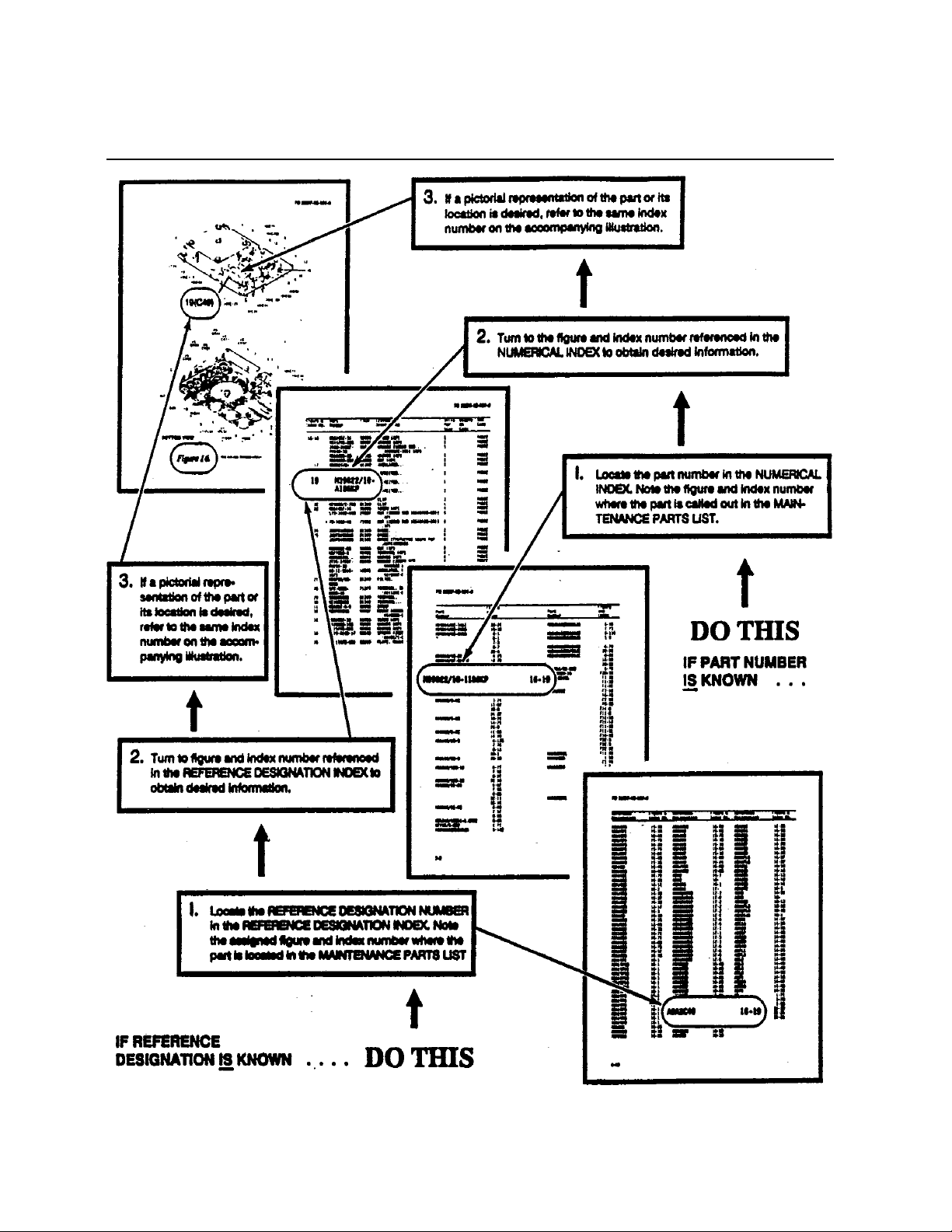
TO 31R2-2TRC207-1
HOW TO USE THE ILLUSTRATED PARTS BREAKDOWN
7-6

TO 31R2-2TRC207-1
This Page Left Blank Intentionally
7-7

TO 31R2-2TRC207-1
Section II. MAINTENANCE PARTS LIST
7-8
Figure 7-1. Radio Set AN/TRC-207 (Sheet 1 of 2)

Figure 7-1. Radio Set AN/TRC-207 (Sheet 2 of 2)
TO 31R2-2TRC207-1
7-9

TO 31R2-2TRC207-1
31R2-2TRC207-1
Table 7-1. Radio Set AN/TRC-207
Figure &
Index No.
Part Number CAGE
1 2 3 4 5 6 7
Description
7-1 4101025-501 23386 Radio Set AN/TRC-207 ..............................
Units per
Assy
Usable
on Code
SMR Code
0001 PEODDS
(refer to Figure 7-1 for breakdown)
7-1-1
(A1)
7-1-2
(A4,A5)
4101027-501 23386@ BDR Assembly..........................................
(refer to Figure 7-2 for breakdown)
SS-4100807-512 23386@ Receiver-Transmitter, RT-1695/ TRC-199
(refer to T.O 31R2-2PRC139-3 for
0001 PAOLDT
0002 PAOLDT
breakdown)
7-1-2a SS-3100552-501 23386@@ Case, Transceiver .................................. . 0004 PAOZZN
7-1-3 SS-2400605-2 23386 @ Label, Identification................................... 0001 XB
7-1-4 Not used
7-1-5 SS-4400225-1 23386 @ Frame, Repeater, Weldment ...................... 0001 XB
7-1-6 SS-3100546-501 23386@ Clamp Assy, Rear ...................................... 0001 XB
7-1-7 MS51957-79 96906@ Screw, Machine .........................................
0002 PAOZZN
(23386/77682) (SPEC CTRL DRW)
7-1-8 MS35338-139 96906@ Washer, Lock.............................................
0008 PAOZZN
(23386/75006) (SPEC CTRL DRW)
7-1-9 MS15795-810 96906@ Washer, Flat...............................................
0014 PAOZZN
(23386/75029) (SPEC CTRL DRW)
7-1-10 MS51957-84 96906@ Screw, Machine .........................................
0001 PAOZZN
(23386/77682) (SPEC CTRL DRW)
7-1-11
SS-3500279-504 23386@ Strap Assy, Ground.................................... 0001 MDF
(W7)
7-1-12
SS-3500279-503 23386@ Strap Assy, Ground.................................... 0001 MDF
(W6)
7-1-13 MS35690-410 96906@ Nut, Plain Hex ...........................................
0007 PAOZZN
(23386/75211) (SPEC CTRL DRW)
7-1-14 71206 73734@ Nut, Wing ..................................................
0001 PAOZZN
(23386/SS-754007) (SPEC CTRL DRW)
7-1-15 MS35650-104 96906@ Nut, Plain, Hexagon...................................
0024 PAOZZN
(23386/75210) (SPEC CTRL DRW)
7-1-16 MS35338-138 96906@ Washer, Lock.............................................
0028 PAOZZN
(23386/75005) (SPEC CTRL DRW)
7-1-17 MS15795-842 96906@ Washer, Flat...............................................
0048 PAOZZN
(23386/SS-75037) (SPEC CTRL DRW)
7-1-18 9286-A194-16AB 06540@ Spacer ........................................................
0048 PAOZZN
(23386/SS-SP04-030) (SPEC CTRL
DRW)
7-1-19 SS-3400353-1 23386@ Bumpers TR, Frame................................... 0024 XB
7-10

TO 31R2-2TRC207-1
Figure &
Index No.
Part Number CAGE
1 2 3 4 5 6 7
Description
7-1-20 MS51958-73 96906@ Screw, Machine..........................................
Units per
Assy
Usable
on Code
SMR Code
0024 PAOZZN
(23386/SS-77776) (SPEC CTRL DRW)
7-1-21
(A2)
4101028-501 23386 @ Power Supply .............................................
(refer to T.O 31R2-2TRC-207-3 for
0001 PAOLDT
breakdown)
7-1-22 MS51957-87 96906 @ Screw, Machine..........................................
0004 PAOZZN
(23386/SS-77691) (SPEC CTRL DRW)
7-1-23
SS-3500292-503 23386@ Cable Assy, Coaxial ................................... 0001 XB
(W4)
7-1-24 SS-2400578-1 23386@ Washer, Shock Mount................................ 0016 XB
7-1-25 MS51958-61 96906@ Screw, Machine..........................................
0004 PAOZZN
(23386/77763) (SPEC CTRL DRW)
7-1-26 MS21919WDG7 96906@ Clamp, Cable..............................................
0002 PAOZZN
(23386/SS-81281) (SPEC CTRL DRW)
7-1-27 SS-2400577-1 23386@ Bushing, Shock Mount............................... 0008 XB
7-1-28 9268-A257-16 06540@ Spacer.........................................................
0008 PAOZZN
(23386/SS-SP04-031) (SPEC CTRL
DRW)
7-1-29 MS21919WDG4 96906@ Cable, Clamp..............................................
(23386/SS-81284) (SPEC CTRL DRW)
7-1-30
SS-3500292-504 23386@ Cable Assy, Coaxial ................................... 0001 XB
(W2)
7-1-31
SS-3500292-505 23386@ Cable Assy, RF Coaxial ............................. 0001 XB
(W3)
7-1-32
4500117-501 23386@ Cable Assembly, Power Supply ................. 0001 PAOZZN
(W1)
7-1-33
SS-1600322-501 23386@ Diplexer Assembly 30-88 MHz.................. 0001 PAODDT
(A3)
7-1-33
SS-1600322-502 23386@ Diplexer Assembly 136-174 MHz ............. 0001 PAODDT
(A3)
7-1-33
SS-1600322-503 23386@ Diplexer Assembly 403-470 MHz.............. 0001 PAODDT
(A3)
7-1-34
SS-3500279-502 23386@ Strap Assy, Ground .................................... 0001 MDF
(W5)
7-1-35 MS51957-85 96906@ Screw, Machine..........................................
(23386/77689) (SPEC CTRL DRW)
7-1-36 5712-61-63* 86928@ Washer, Flat ...............................................
(23386/75171) (SPEC CTRL DRW)
0002 PAOZZN
0006 PAOZZN
0008 PAOZZN
7-1-37 SS-3400355-1 23386@ Clamp, Front .............................................. 0001 XB
7-1-38 4266-RAC 23657@ Antenna, 403-470 MHz..............................
0001 PAOZZN
(23386/SS-1600230-3) (SPEC CTRL
DRW)
7-11

TO 31R2-2TRC207-1
Figure &
Index No.
Part Number CAGE
1 2 3 4 5 6 7
Description
7-1-39 SP10SS 1BZ19@ Mast Kit, Tactical Repeater .......................
Units per
Assy
Usable
on Code
SMR Code
0001 PAOZZN
(23386/SS-1600281-1) (SPEC CTRL
DRW)
7-1-39a SL/33644 1BZ19 $ $ Antenna Adapter ................................... 0001 PAOZZN
7-1-39b SL33641SH1 1BZ19 $ $ Top Guy Rope Assy (Green) ................ 0003 PAOZZN
7-1-39c SL33641SH2 1BZ19 $ $ Middle Guy Rope Assy (Black) ........... 0003 PAOZZN
7-1-39d AR31EF 1BZ19 $ $ Mast Section ........................................ 0002 PAOZZN
7-1-39g F209 1BZ19 $ $ Base Plate.............................................. 0001 PAOZZN
7-1-39h SL32223 1BZ19 $ $ Ground Anchor ..................................... 0003 PAOZZN
7-1-39j DG33640 1BZ19 $ $ Guy Plate............................................... 0001 PAOZZN
7-1-39k Q86 1BZ19 $ $ Ground Spike ........................................ 0002 POAZZN
7-1-39l SL33642-1 1BZ19 $ $ Transit Bag............................................ 0001 PAOZZN
7-1-40 4265-RAC 23657@ Antenna,136-174 MHz ..............................
0001 PAOZZN
(23386/SS-1600230-2) (SPEC CTRL
DRW)
7-1-41 4242-MK2-RAC 23657@ Antenna,30-88 MHz ..................................
0001 PAOZZN
(23386/SS-1600230-1) (SPEC CTRL
DRW)
7-1-42
(W10)
7-1-44 275-160-070-000 52473@ Case, Transit, Diplexer ..............................
CPRG223/U-30-XX 79557@ Cable, Coaxial, Antenna............................
(23386/SS-1600315-1) (SPEC CTRL
DRW)
0001 PAOZZN
0001 PAOZZN
(23386/SS-1600352-1) (SPEC CTRL
DRW)
7-1-45 SS-3100551-501 23386@ Rod Assy, Ground ..................................... 0001 PAOZZN
7-1-46
SS-4500108-501 23386@ Cable Assembly, TR 240 V ....................... 0001 PAOZZN
(W9)
7-1-47
SS-4500107-501 23386@ Cable Assembly, TR 120 V ....................... 0001 PAOZZN
(W9)
7-1-48
SS-4500109-501 23386@ Cable Assembly, TR 10-32 V.................... 0001 PAOZZN
(W9)
7-1-49 275-160-100-000 52473@ Case, Transit, Diplexer ..............................
0001 PAOZZN
(23386/SS-1600352-2) (SPEC CTRL
DRW)
7-1-50 IC-3300RC 82820@ Cover, Frame .............................................
0001 PAOZZN
(23386/SS-1600354-1) (SPEC CTRL
DRW)
7-12

TO 31R2-2TRC207-1
Figure 7-2. Bi-Directional Repeater Assembly (4101027-501) (Sheet 1 of 3)
7-13

TO 31R2-2TRC207-1
7-14
Figure 7-2. Bi-Directional Repeater Assembly (4101027-501) (Sheet 2 of 3)

TO 31R2-2TRC207-1
Figure 7-2. Bi-Directional Repeater Assembly (4101027-501) (Sheet 3 of 3)
7-15

TO 31R2-2TRC207-1
Table 7-2. Bi-Directional Repeater Assembly (4101027-501)
Figure &
Index No.
Part Number CAGE
1 2 3 4 5 6 7
Description
7-2 4101027-501 23386 Bi-directional Repeater Assembly ..............
Units per
Assy
Usable
on Code
SMR Code
0001 PAOLDT
(refer to Figure 7-2 for breakdown) (ESD)
7-2-1
SS-4100823-502 23386@ Sleeve Assembly, Short ............................ 0001 PADZZN
(A8)
7-2-2 4600070-501 23386@ Chassis Assembly, Altered ....................... 0001 XB
7-2-3
SS-4100823-502 23386@ Sleeve Assembly, Short ............................ 0002 PADZZN
(A9)
7-2-4
4101030-501 23386@ Panel Assembly, Control .......................... 0001 PAOLDT
(A5)
7-2-4a 4101032-501 23386@ @ CCA, Panel, Control (ESD).................... 0001 PADZZN
7-2-5
(A6)
SS-4100853-501 23386@ Power Amplifier Assembly (ESD)...........
(refer to T.O 31R2-2TRC199-3 for
0001 PAOLDT
breakdown)
7-2-6 SS-4400220-1 23386@ Gasket, EMI.............................................. 0001 PADZZN
7-2-7 5710-54-25 86928@ Washer, Flat..............................................
0001 PADZZN
(23386/75106) (SPEC CTRL DRW)
7-2-8 MS15795-810 96906@ Washer, Flat..............................................
0001 PADZZN
(23386/75029) (SPEC CTRL DRW)
7-2-9 MS35333-74 96906 Washer, Int Tooth.......................................
0001 PADZZN
(23386/SS-75066) (SPEC CTRL DRW)
7-2-10 71206 73734@ Nut, Wing .................................................
0001 PADZZN
(23386/SS-754007) (SPEC CTRL DRW)
7-2-11 SS-4400226-1 23386@ Gasket, EMI.............................................. 0001 PADZZN
7-2-12
2500145-502 23386@ Cable, Coaxial, Shield .............................. 0001 PADZZN
(W2)
7-2-13 SS-3400331-1 23386@ Gasket, EMI.............................................. 0001 PADZZN
7-2-14
SS-2500120-501 23386@ Cable Assy, Coaxial.................................. 0001 PADZZN
(W4)
7-2-15 4101047-501 23386 Mounting Plate Assy................................. 0001 PADZZN
7-2-16
4101033-501 23386@ CCA, RF Matrix BDR (ESD). .................. 0001 PADZZN
(A7)
7-2-17 SS-3400357-1 23386@ Cover, Rear............................................... 0001 XB
7-2-18 MS24693-C3 96906 Screw, Flat Head.......................................
0015 PADZZN
(23386/77813)(SPEC CTRL DRW)
7-2-19 AN960-C4 88044@ Washer, Flat..............................................
0026 PAFZZN
(23386/75023) (SPEC CTRL DRW)
7-2-20 MS35338-135 96906@ Washer, Lock............................................
0026 PADZZN
(23386/75002) (SPEC CTRL DRW)
7-2-21 MS51957-14 96906@ Screw, Machine ........................................
(23386/77614) (SPEC CTRL DRW)
7-16
0004 PADZZN

TO 31R2-2TRC207-1
Figure &
Index No.
Part Number CAGE
1 2 3 4 5 6 7
Description
7-2-22 NAS671C4 80205 Nut, Plain Hex..........................................
Units per
Assy
Usable
on Code
SMR Code
0004 PADZZN
(23386/75203)(SPEC CTRL DRW)
7-2-23 SS-4100878-501 23386@ Cover Assy, Bottom ................................. 0001 XB
7-2-24 SS-4400219-1 23386@ Gasket, EMI ............................................. 0001 PADZZN
7-2-25 MS3212-13 96906@ Screw, Panhead ........................................
0016 PADZZN
(23386/79144-632-06) (SPEC CTRL
DRW)
7-2-26 SS-3100531-502 23386@ Bracket Assy, Retaining ........................... 0001 XB
7-2-27 MS15795-806 96906@ Washer, Flat .............................................
0004 PADZZN
(23386/75025) (SPEC CTRL DRW)
7-2-28 MS51957-28 96906@ Screw, Machine........................................
0004 PADZZN
(23386/77628) (SPEC CTRL DRW)
7-2-29
SS-4100811-501 23386@ CCA, Parent Board (ESD) ....................... 0001 PADZZN
(A4)
7-2-30
SS-4100730-501 23386@ CCA, Converter +15V (ESD) .................. 0001 PADZZN
(A1)
7-2-31 SS-3100532-502 23386@ Bracket Assy, Retaining ........................... 0001 XB
7-2-32
(A3)
7-2-33
(A2)
4101050-501 23386 CCA, Repeater Interface .......................... 0001 PADZZN
4101029-501 23386@ CCA, Control, Repeater BDR (ESD).......
0001 PAOLDT
(refer to T.O 31R2-2TRC199-3 for
breakdown)
7-17

TO 31R2-2TRC207-1
This Page Left Blank Intentionally
7-18

TO 31R2-2TRC207-1
Figure 7-3. Power Amplifier Assembly, 15W (SS-4100853-501)
7-19

TO 31R2-2TRC207-1
Table 7-3. Power AMP Assembly, 15W (SS-4100853-501)
Figure &
Index No.
Part Number CAGE
Description
1 2 3 4 5 6 7
Units per
Assy
Usable
on Code
SMR Code
7-3 SS-4100853-501 23386 Power Amplifier Assy, 15W (ESD)............ 0001 PAOLDT
7-3-1 MS3212-15 96906@ Screw, Machine ........................................
0006 PADZZN
(23386/79144-632-08) (SPEC CTRL
DRW)
7-3-2 1026-250-SS-26 40337 Retainer, Panel Screw............................... 0020 XB
7-3-3 107-SS-26 40337 Screw, Captive, Panel............................... 0020 XB
7-3-4 1055-SS 40337 Spring, Panel Screw.................................. 0020 XB
7-3-5 SS-4100836-501 23386@ Cover, Heatsink, TR ................................. 0001 XB
7-3-6 SS-4100855-501 23386@ Amplifier Assy,15W (ESD)......................
(refer to T.O. 31R2-4-1085-5 for
breakdown)
7-3-7
2500147-501 23386@ Cable Assy, Coaxial.................................. 0001 PADZZN
(W9)
7-3-8 F4NY-312BK 85480@ Cable, Clamp ............................................
0002 PADZZN
(23386/81254) (SPEC CTRL DRW)
7-3-9 AN960-C4 88044@ Washer, Flat..............................................
0002 PADZZN
(23386/75023) (SPEC CTRL DRW)
7-3-10 MS51957-14 96906@ Screw, Machine ........................................
(23386/77614) (SPEC CTRL DRW)
7-3-11
SS-3500281-501 23386 Cable Assy, Amplifier Control ................. 0001 PADZZN
(A6W1)
7-3-12
SS-2500122-501 23386 Cable Assy, Amplifier Power ................... 0001 PADZZN
(A6W9)
0002 PADZZN
7-20

Section III. NUMERICAL INDEX
TO 31R2-2TRC207-1
Part Number
Figure &
Part Number
Index No.
1026-250-SS-26 7-3-2 AN960-C4 7-3-9 MS51957-84 7-1-10
1055-SS 7-3-4 AN960-C4 7-2-19 MS51957-85 7-1-35
107-SS-26 7-3-3 AR31EF 7-1-39d MS51957-87 7-1-22
2500145-502 7-2-12
(W2)
2500147-501 7-3-7
(W9)
275-160-070-000 7-1-44 F209 7-1-39g NAS671C4 7-2-22
275-160-100-000 7-1-49 F4NY-312BK 7-3-8 Q86 7-1-39k
4101025-501 7-1 IC-3300RC 7-1-50 SL/33644 7-1-39a
4101027-501 7-2 MS15795-806 7-2-27 SL32223 7-1-39h
4101027-501 7-1-1
(A1)
4101028-501 7-1-21
(A2)
4101029-501 7-2-33
(A2)
CPRG223/U-30-XX 7-1-42
DG33640 7-1-39j MS51958-73 7-1-20
MS15795-810 7-2-8 SL33641SH1 7-1-39b
MS15795-810 7-1-9 SL33641SH2 7-1-39c
MS15795-842 7-1-17 SL33642-1 7-1-39l
Figure &
Index No.
(W10)
Part Number
Figure &
Index No.
MS51958-61 7-1-25
4101030-501 7-2-4
(A5)
4101032-501 7-2-4a MS21919WDG4 7-1-29 SS-1600322-501 7-1-33
4101033-501 7-2-16
(A7)
4101047-501 7-2-15 MS24693-C3 7-2-18 SS-1600322-503 7-1-33
4101050-501 7-2-32
(A3)
4242-MK2-RAC 7-1-41 MS3212-15 7-3-1 SS-2400578-1 7-1-24
4265-RAC 7-1-40 MS35333-74 7-2-9 SS-2400605-2 7-1-3
4266-RAC 7-1-38 MS35338-135 7-2-20 SS-2500120-501 7-2-14
4500117-501 7-1-32
(W1)
4600070-501 7-2-2 MS35338-139 7-1-8 SS-3100531-502 7-2-26
5710-54-25 7-2-7 MS35650-104 7-1-15 SS-3100532-502 7-2-31
5712-61-63* 7-1-36 MS35690-410 7-1-13 SS-3100546-501 7-1-6
MS21318-20* 7-1-4 SP10SS 7-1-39
(A3)
MS21919WDG7 7-1-26 SS-1600322-502 7-1-33
(A3)
(A3)
MS3212-13 7-2-25 SS-2400577-1 7-1-27
(W4)
MS35338-138 7-1-16 SS-2500122-501 7-3-12
(A6W9)
71206 7-1-14 MS51957-14 7-3-10 SS-3100551-501 7-1-45
71206 7-2-10 MS51957-14 7-2-21 SS-3100552-501 7-1-43
7-21

TO 31R2-2TRC207-1
Part Number
Figure &
Part Number
Index No.
9268-A257-16 7-1-28 SS-3500292-505 7-1-31
9286-A194-16AB 7-1-18 SS-4100730-501 7-2-30
MS51957-28 7-2-28 SS-4100807-512 7-1-2
MS51957-79 7-1-7 SS-4100811-501 7-2-29
SS-3400331-1 7-2-13 SS-4100823-502 7-2-3
SS-3400353-1 7-1-19 SS-4100823-502 7-2-1
SS-3400355-1 7-1-37 SS-4100836-501 7-3-5
SS-3400357-1 7-2-17 SS-4100853-501 7-2-5
SS-3500279-502 7-1-34
(W5)
SS-4100853-501 7-3
Figure &
Index No.
(W4)
(A1)
(A4, A5)
(A4)
(A9)
(A8)
(A6)
Part Number
Figure &
Index No.
SS-4400225-1 7-1-5
SS-4400226-1 7-2-11
SS-4500107-501 7-1-47
(W9)
SS-4500108-501 7-1-46
(W9)
SS-4500109-501 7-1-48
(W9)
SS-3500279-503 7-1-12
(W6)
SS-3500279-504 7-1-11
(W7)
SS-3500281-501 7-3-11
(A6W1)
SS-3500292-503 7-1-23
(W3)
SS-3500292-504 7-1-30
(W2)
SS-4100855-501 7-3-6
SS-4100878-501 7-2-23
SS-4400219-1 7-2-24
SS-4400220-1 7-2-6
7-22

Section IV. REFERENCE DESIGNATION INDEX
TO 31R2-2TRC207-1
Reference Designator Figure & Item
Number
Radio Set AN/TRC-207 7-1-REF A9 7-2-3
A1 7-1-1 W2 7-2-12
A2 7-1-21 W4 7-2-14
A3 7-1-33 W9 7-3-7
A3 7-1-33
A3 7-1-33
A4,A5 7-1-2
W1 7-1-32
W2 7-1-30
W3 7-1-23
W4 7-1-31
W5 7-1-34
W6 7-1-12
W7 7-1-11
W9 7-1-48
W9 7-1-46
W9 7-1-47
W10 7-1-42
Bi-directional Repeater
Assembly (4101027-501)
A1 7-2-30
A2 7-2-33
A3 7-2-32
A4 7-2-29
A5 7-2-4
A6 7-2-5
A7 7-2-16
A8 7-2-1
7-2-REF
Reference Designator Figure & Item
Number
Reference Designator Figure & Item
Number
7-23

TO 31R2-2TRC207-1
Section V. COMMON BULK ITEMS LIST
Part Number CAGE Code Description Unit of Measure
No 222 50CC 05972 Threadlocking Compound No. 222
(23386/91172)
A/R
7-24

CHAPTER 8 CIRCUIT DIAGRAMS
8-1 SCOPE
This chapter contains the following diagram:
Figure No. Title
8-1 Radio Set AN/TRC-207, Interconnection Diagram
TO 31R2-2TRC207-1
8-1/(8-2 blank)

TO 31R2-2TRC207-1
8-2

TO 31R2-2TRC207-1
Figure 8-1. Radio Set AN/TRC-207, Interconnection Diagram
8-3/(8-4 blank)


TO 31R2-2TRC207-1
GLOSSARY
AC Alternating current
ALC Automatic level control
ANT Antenna
ASSY Assembly
BDR Bi-directional Repeater
C Celsius (centigrade)
CCA Circuit card assembly
CCI Controlled cryptographic item
CLR Clear
CM Centimeter
CTCSS Continuous tone-controlled squelch system
CTRL Control
CW Continuous wave
dB Decibels
dBi Decibel (isotropic)
dBD Decibels relative to a 1/2 wavelength dipole
dBm Power in decibels (referenced to 1 milliwatt)
DC Direct current
DRW Drawing
ESD Electrostatic discharge
ESDS Electrostatic discharge sensitive
EXT External
F Fahrenheit
FM Frequency modulation (modulated)
GND Ground
HF High frequency
HZ Hertz
IF Intermediate frequency
in. Inch
INT Internal
kbps Kilobits/second
kg Kilogram
kHz Kilohertz
Lbs Pounds
LED Light emitting diode
MHz Megahertz
NiCad Nickel Cadmium
PTT Push-to-talk
RCV Receive
RX Receiver
SINAD Signal + noise + distortion power/noise + distortion power, expressed in dB
SPEC Specification
SMR Source, Maintenance and Recoverability
TUNERX Tune receiver
TUNETX Tune transmitter
TX Transmitter
UHF Ultra high frequency
VVolt
VAC Volts alternating current
VHF Very high frequency
WWatt
GLOSSARY-1/(GLOSSARY-2 blank)


TO 31R2-2TRC207-1
ALPHABETICAL INDEX
Paragraph, Figure,
Subject or Table Number
A
Antenna Assembly:
Description P1-1.2.3
Removal and Replacement Procedures P6-5.1.2
B
Bi-directional repeater Assembly:
Description P1-1.2.1, F7-2
Indicators, Controls, and Switches T4-1, F4-1
Removal and Replacement Procedures P6-5.6.7
C
Cables, Interconnecting T2-2
Capabilities and Limitations P1-3, T1-3
Control Panel Assembly (A5):
Functional System Operation P5-2.4
Removal/Replacement Procedures P6-5.2.2
Controls and Indicators: P4-2
Diplexer Controls T4-4, F4-4
Indicators, Controls, and Switches T4-1, F4-1
Power Switches T4-2, F4-2
Connectors T4-3, F4-3
Cross-banding P4-3.2.6
D
DC-DC Converter CCA (A7):
Functional System Operation P5-2.6
Description, Equipment:
Antenna Assembly P1-1.2.3
Diplexer P1-1.2.4, F1-3
Power Supply Assembly P1-1.2.5
Receiver-Transmitters P1-1.2.2, F1-2
Bi-directional repeater Assembly P1-1.2.1, F7-1
Diplexer:
Controls T4-4, F4-4
Description P1-1.2.4, F1-3
Removal and Replacement Procedures P6-5.1.6
E
Equipment
Description P1-1.2
Function and Purpose P1-1.1
Equipment Required but not Supplied P1-5, T1-5
Equipment Supplied P1-4, T1-4
INDEX-1

TO 31R2-2TRC207-1
Paragraph, Figure,
Subject or Table Number
F
Functional Operation of Electronic Circuits
Repeater Control CCA (A3) P5-3, F5-2
15 Watt Power Amplifier Assembly (A6) P5-4, F5-3
Functional System(s) Operation P5-2
AC/DC Power Supply (A2) P5-2.10
Antenna System P5-2.8
Control Panel (A5) P5-2.4
Diplexer P5-2.9
Parent Board CCA (A4) P5-2.3
Receiver-Transmitter P5-2.7
Repeater Control CCA (A2) P5-2.2
RF Power Amplifier Assembly (A6) P5-2.5
+15V DC-DC Converter CCA (A1) P5-2.1
+28V DC-DC Converter CCA (A7) P5-2.6
H
Handling and Storage P3-6
Handling, Material P2-6
I
Installation:
Buildings and Other Support Structures P2-8
Cables P2-7, T2-2
Housing P2-4
Installation Sequence: P2-10
Antenna/Mast Installation P2-10.1
Diplexer Installation P2-10.5
External Power Supply P2-10.4
Ground Rod Installation P2-10.3
Lithium Battery Installation P2-10.2
Receiver-Transmitter Transceiver Module Installation P2-10.6
Material Handling P2-6
Packing P3-5, F2-1
Receiving Data P2-5, T2-1
Site Preparation P2-2
Special Tools and Test Equipment Required P2-9
Unpacking and Inspections P2-3
Interconnection Diagram 8-1
INDEX-2
 Loading...