


TO 31R2-2TRC199-1
OPERATION AND MAINTENANCE INSTRUCTIONS WITH ILLUSTRATED PARTS BREAKDOWN
ORGANIZATIONAL LEVEL
RADIO SET
AN/TRC-199
(TACTICAL REPEATER)
RACAL COMMUNICATIONS, INC.
5 RESEARCH PLACE
ROCKVILLE, MD 20850
CONTRACT NO: F19628-91-D-0012
DISTRIBUTION STATEMENT B - Distribution authorized to U.S. Government agencies only for administrative or operational use 15 June, 1993. Other requests for this document shall be referred to Sacramento ALC/TILBE, 3200 Peacekeeper Way, Suite 1, McClellan AFB, CA 95652-1026.
WARNING - This document contains technical data whose export is restricted by the Arms Export Control Act (Title 22, U.S.C., Sec 2751 et seq) or the Export Administration Act of 1979, as amended (Title 50, U.S.C., App 2401 et seq). Violations of these export laws are subject to severe criminal penalties.
HANDLING AND DESTRUCTION NOTICE - Handle in compliance with distribution statement and destroy by any method that will prevent disclosure of contents or reconstruction of the document.
PUBLISHED UNDER AUTHORITY OF THE SECRETARY OF THE AIR FORCE
15 JUNE 1993
CHANGE 1 - 10 AUGUST 1994

TO 31R2-2TRC199-1
INSERT LATEST CHANGE PAGES, DESTROY SUPERSEDED PAGES.
LIST OF EFFECTIVE PAGES
NOTE: The portion of the text affected by the changes is indicated by a vertical line in the outer margin of the page. Changes to illustrations are indicated by a vertical line adjacent to the illustration identification number.
DATES OF ISSUE FOR ORIGINAL AND CHANGED PAGES ARE:
|
ORIGINAL |
0 |
15 JUNE 1993 |
|
|
|
CHANGE |
1 |
10 AUGUST 1994 |
|
|
TOTAL NUMBER OF PAGES IN THIS PUBLICATION IS 108 CONSISTING OF THE FOLLOWING: |
|
||||
Page |
* Change |
Page |
* Change |
Page |
* Change |
No. |
No. |
No. |
No. |
No. |
No. |
Title page................... |
1 |
A ................................ |
1 |
B ............................... |
1 |
i ................................. |
0 |
ii ................................. 1 iii................................. 0 iv................................ 1 v.................................. 0 vi................................. 1 vii................................ 0 viii blank..................... 0 ix................................ 0 1-0 - 1-2 ..................... 0 1-3 - 1-4 ..................... 1 1-5.............................. 0 1-6 - 1-7 ..................... 1 1-8.............................. 0 2-1 - 2-4 ..................... 0
2-5 - 2-9 ..................... 1
2-10 blank.................. 0
3-1 - 3-4 ..................... 0
4-1 ............................. 1
4-2.............................. 0
4-3 - 4-7 ...................... 1
4-8............................... 0
4-9............................... 1
4-10 blank.................. 0
5-1 - 5-6 ..................... 0
6-1 - 6-13 ................... 0
6-14 blank.................. 0
7-1 - 7-24 ................... 0
8-1.............................. 0
8-2 blank.................... 0
FP-1 ........................... 1 FP-2 blank ................. 0 GLOSSARY-1........... 0 GLOSSARY-2 blank . 0
INDEX-1 - 4 ............. 0
* Zero in this column indicates an original page.
USAF
Change 1 |
A |
|
|
|
TO 31R2-2TRC199-1 |
|
|
|
RECORD OF CHANGES |
|
|
|
|
|
|
|
CHANGE |
DATE |
TITLE OR BRIEF DESCRIPTION |
ENTERED BY |
|
NO. |
|
|
|
|
|
|
|
|
|
1 |
10 August 1994 |
|
|
|
|
|
|
|
|
|
|
|
|
|
|
|
|
|
|
|
|
|
|
|
|
|
|
|
|
|
|
|
|
|
Change 1 |
B |
|
TO 31R2-2TRC199-1 |
|
TABLE OF CONTENTS |
Chapter |
Page |
LIST OF ILLUSTRATIONS .........................................................................................................................iv LIST OF TABLES .........................................................................................................................................iv SAFETY SUMMARY ....................................................................................................................................v FOREWORD .................................................................................................................................................ix
CHAPTER 1.0 GENERAL INFORMATION....................................................................................................... 1-3
1-1 |
DESCRIPTION AND PURPOSE. ....................................................................................................1-3 |
|
|
1-1.1 |
Equipment Function and Purpose. ...................................................................................1-3 |
|
1-1.2 |
Equipment Description. ...................................................................................................1-3 |
1-2 |
LEADING PARTICULARS. ............................................................................................................1-5 |
|
1-3 |
CAPABILITIES AND LIMITATIONS. ...........................................................................................1-6 |
|
1-4 |
EQUIPMENT SUPPLIED. ...............................................................................................................1-7 |
|
|
1-4.1 |
EQUIPMENT REQUIRED BUT NOT SUPPLIED. ......................................................1-8 |
1-5 SPECIAL TOOLS AND TEST EQUIPMENT. ................................................................................1-8 |
||
1-6 |
RELATED TECHNICAL MANUALS. ............................................................................................1-8 |
|
CHAPTER 2.0 INSTALLATION .......................................................................................................................... 2-1
2-1 INTRODUCTION.............................................................................................................................2-1 Section I. INSTALLATION LOGISTICS ..................................................................................................2-1
2-2 |
SITE PREPARATION. .....................................................................................................................2-1 |
2-3 |
UNPACKING AND INSPECTIONS................................................................................................2-1 |
2-4 |
HOUSING. ........................................................................................................................................2-3 |
2-5 |
RECEIVING DATA..........................................................................................................................2-3 |
2-6 |
MATERIAL HANDLING.................................................................................................................2-3 |
2-7 |
CABLES............................................................................................................................................2-4 |
2-8 BUILDING AND OTHER SUPPORTING STRUCTURES. ...........................................................2-4
Section II. INSTALLATION PROCEDURES............................................................................................2-5
2-9 |
SPECIAL TOOLS AND EQUIPMENT REQUIRED FOR FIELD INSTALLATION. ...................2-5 |
|
2-10 |
INSTALLATION SEQUENCE.........................................................................................................2-5 |
|
|
2-10.1 |
Antenna/Mast Installation. ...............................................................................................2-5 |
|
2-10.2 |
Lithium Battery Installation. ............................................................................................2-9 |
|
2-10.3 |
Ground Rod Installation...................................................................................................2-9 |
|
2-10.4 |
External Power Supply. ...................................................................................................2-9 |
|
2-10.5 |
Diplexer Installation. .......................................................................................................2-9 |
|
2-10.6 Receiver-Transmitter Transceiver Module Installation....................................................2-9 |
|
CHAPTER 3.0 PREPARATION FOR USE AND RESHIPMENT .................................................................. 3-10
3-1 INTRODUCTION...........................................................................................................................3-10 Section I. PREPARATION FOR USE ......................................................................................................3-10
3-2 |
INSPECTION..................................................................................................................................3-10 |
|
3-3 |
POST-INSTALLATION CHECKOUT...........................................................................................3-10 |
|
|
3-3.1 |
Preliminary.....................................................................................................................3-10 |
|
3-3.2 |
Alignment and Adjustment. .............................................................................................3-2 |
|
3-3.3 |
Post-Installation Checkout Procedures. ...........................................................................3-2 |
Section II. PREPARATION FOR RESHIPMENT .....................................................................................3-2 |
||
3-4 |
PREPARING UNIT FOR RESHIPMENT........................................................................................3-2 |
|
3-5 |
PACKING. ........................................................................................................................................3-2 |
|
3-6 |
HANDLING AND STORAGE. ........................................................................................................3-2 |
|
|
3-6.1 |
Protective Measures for Electrical Connectors. ...............................................................3-3 |
|
3-6.2 |
Preparation for Shipment and Storage. ............................................................................3-3 |
|
3-6.3 |
Handling. .........................................................................................................................3-3 |
i

TO 31R2-2TRC199-1
CHAPTER 4.0 OPERATION ................................................................................................................................. 4-1
4-1 |
INTRODUCTION. ........................................................................................................................... 4-1 |
|
4-2 |
CONTROLS AND INDICATORS. .................................................................................................. 4-1 |
|
|
4-2.1 |
Indicators, Controls and Switches. .................................................................................. 4-1 |
|
4-2.2 |
Power Supply Switches and Connectors. ........................................................................ 4-1 |
|
4-2.3 |
Connectors....................................................................................................................... 4-1 |
|
4-2.4 |
Diplexer Controls. ........................................................................................................... 4-1 |
Section II. OPERATING INSTRUCTIONS .............................................................................................. 4-7 |
|
4-3 |
INITIAL POWER-UP AND DIPLEXER TUNING PROCEDURES.............................................. 4-7 |
4-4 |
RECEIVING AND RETRANSMITTING MESSAGE. ................................................................... 4-8 |
4-5 |
COVERT OPERATIONS................................................................................................................. 4-8 |
|
4-6 |
RECEIVER-TRANSMITTERS........................................................................................................ 4-8 |
|
4-7 |
EQUIPMENT SHUTDOWN............................................................................................................ 4-8 |
|
Section III. EMERGENCY OPERATION ................................................................................................. 4-8 |
||
4-8 |
EMERGENCY POWER................................................................................................................... 4-8 |
|
4-9 |
ELECTROMAGNETIC PULSE PROTECTION............................................................................. 4-9 |
|
|
4-9.1 |
EMP Susceptibility.......................................................................................................... 4-9 |
|
4-9.2 |
EMP Protective Measures. .............................................................................................. 4-9 |
4-10 NUCLEAR, BIOLOGICAL, AND CHEMICAL(NBC) CONTAMINATION ................................ 4-9
CHAPTER 5.0 THEORY OF OPERATION ........................................................................................................ 5-1
Section I. FUNCTIONAL SYSTEM(S) OPERATION.............................................................................. 5-1
5-1 |
GENERAL. ....................................................................................................................................... 5-1 |
|
5-2 |
FUNCTIONAL SYSTEM(S) OPERATION. ................................................................................... 5-1 |
|
|
5-2.1 +15V DC-DC Converter Circuit Card Assembly (CCA) (A1)........................................ 5-1 |
|
|
5-2.2 Repeater Control Circuit Card Assembly (CCA) (A3).................................................... 5-1 |
|
|
5-2.3 Parent Board Circuit Card Assembly (CCA) (A4). ......................................................... 5-1 |
|
|
5-2.4 |
Control Panel (A5). ......................................................................................................... 5-1 |
|
5-2.5 RF Power Amplifier Assembly (A6). .............................................................................. 5-1 |
|
|
5-2.6 +28V DC-DC Converter Circuit Card Assembly (CCA) (A7)........................................ 5-3 |
|
|
5-2.7 |
Receiver-Transmitter....................................................................................................... 5-3 |
|
5-2.8 |
Antenna System............................................................................................................... 5-3 |
|
5-2.9 |
Diplexer........................................................................................................................... 5-3 |
|
5-2.10 |
AC/DC Power Supply (A2)............................................................................................. 5-3 |
Section II. FUNCTIONAL OPERATION OF ELECTRONIC CIRCUITS ............................................... 5-4 |
||
5-3 |
REPEATER CONTROL CIRCUIT CARD ASSEMBLY (CCA) (A3)............................................ 5-4 |
|
5-4 15 WATT POWER AMPLIFIER ASSEMBLY (A6)....................................................................... 5-4 Section III. FUNCTIONAL OPERATION OF MECHANICAL ASSEMBLIES ...................................... 5-4
CHAPTER 6.0 MAINTENANCE........................................................................................................................... 6-1
6-1 |
GENERAL. ....................................................................................................................................... 6-1 |
|
6-2 |
OPERATIONAL CHECKOUT. ....................................................................................................... 6-1 |
|
|
6-2.1 |
Power-up Verification. .................................................................................................... 6-1 |
|
6-2.2 |
Display Off Control......................................................................................................... 6-1 |
|
6-2.3 |
Receive Tune Mode Verification. ................................................................................... 6-2 |
|
6-2.4 |
Transmit Tune Mode Verification................................................................................... 6-2 |
|
6-2.5 |
Fault LED........................................................................................................................ 6-3 |
6-3 |
SERVICING. .................................................................................................................................... 6-3 |
|
|
6-3.1 |
Servicing Intervals........................................................................................................... 6-3 |
|
6-3.2 |
Inspection. ....................................................................................................................... 6-3 |
|
6-3.3 |
Preventive Maintenance. ................................................................................................. 6-3 |
6-4 |
TROUBLESHOOTING.................................................................................................................... 6-4 |
|
6-5 |
REMOVAL/REPLACEMENT PROCEDURES. ........................................................................... 6-10 |
|
|
6-5.1 |
Removal/Replacement Procedures - Operator............................................................... 6-10 |
|
6-5.2 |
Removal/Replacement Procedures - Repair Specialist.................................................. 6-12 |
ii |
|
Change 1 |
TO 31R2-2TRC199-1
CHAPTER 7.0 ILLUSTRATED PARTS BREAKDOWN................................................................................... 7-1
Section I. INTRODUCTION ......................................................................................................................7-1
7-1 |
GENERAL.........................................................................................................................................7-1 |
7-2 |
MAINTENANCE PARTS LIST. ......................................................................................................7-1 |
7-3 |
NUMERICAL INDEX. .....................................................................................................................7-2 |
7-4 |
REFERENCE DESIGNATION INDEX. ..........................................................................................7-3 |
7-5 ELECTROSTATIC DISCHARGE (ESD) SENSITIVE DEVICES..................................................7-3 |
|
7-6 |
CAGE CODE SUMMARY. ..............................................................................................................7-4 |
Section II. MAINTENANCE PARTS LISTS ...........................................................................................7-10
Section III. NUMERICAL INDEX ...........................................................................................................7-21
Section IV. REFERENCE DESIGNATION INDEX................................................................................7-23
Section V. COMMON BULK ITEMS LIST.............................................................................................7-24
CHAPTER 8.0.......................................................................................................................................................... 8-1
8-1 SCOPE...............................................................................................................................................8-1
GLOSSARY
ALPHABETICAL INDEX
iii

TO 31R2-2TRC199-1
LIST OF ILLUSTRATIONS
Figure 1-1. |
Radio Set AN/TRC-199......................................................................................................................... 1-0 |
|
Figure 1-2. |
Receiver-Transmitter RT-1695/TRC-199.............................................................................................. 1-4 |
|
Figure 1-3. Diplexer Front Panel (30-88 MHz)........................................................................................................ 1-4 |
||
Figure 2-1. Packaging Diagram for the Tactical Repeater ....................................................................................... 2-2 |
||
Figure 2-2. |
Antenna Mast/Antenna Installation |
(Sheet 1 of 6)................................................................................ 2-5 |
Figure 2-3. |
Antenna Mast/Antenna Installation |
(Sheet 2 of 6)................................................................................ 2-6 |
Figure 2-4. |
Antenna Mast/Antenna Installation |
(Sheet 3 of 6)................................................................................ 2-6 |
Figure 2-5. |
Antenna Mast/Antenna Installation |
(Sheet 4 of 6)................................................................................ 2-7 |
Figure 2-6. |
Antenna Mast/Antenna Installation |
(Sheet 5 of 6)................................................................................ 2-7 |
Figure 2-7. |
Antenna Mast/Antenna Installation |
(Sheet 6 of 6)................................................................................ 2-8 |
Figure 4-1. Location of Tactical Repeater Indicators, Controls and Switches ......................................................... 4-1 |
||
Figure 4-2. Location of Power Supply Switches (Power Supply Top View) ........................................................... 4-3 |
||
Figure 4-3. |
Location of Power Supply Connectors (Power Supply Side View)...................................................... 4-4 |
|
Figure 4-4. Location of Tactical Repeater Unit Connectors..................................................................................... 4-5 |
||
Figure 4-5. Location of Tactical Repeater Diplexer Controls .................................................................................. 4-6 |
||
Figure 5-1. Tactical Repeater System, Functional Block Diagram .......................................................................... 5-2 |
||
Figure 5-2. Repeater Control CCA (A3), Functional Block Diagram ...................................................................... 5-5 |
||
Figure 5-3. 15 Watt Power Amplifier Assembly (A6), Functional Block Diagram ................................................. 5-6 |
||
Figure 7-1. |
Radio Set AN/TRC-199 (Sheet 1 of 2)................................................................................................... 7-8 |
|
Figure 7-2. Tactical Repeater Assembly (SS-4100806-501)................................................................................. 7-13 |
||
Figure 7-3. |
Power Amp Assembly, 15W (SS-4100853-501)................................................................................... 7-19 |
|
FO-1 |
Radio Set AN/TRC-199, Interconnection Diagram ............................................................................. FP-1 |
|
|
LIST OF TABLES |
Table 1-1. |
Tactical Repeater Configurations (by Frequency Band)........................................................................ 1-3 |
Table 1-2. |
Leading Particulars ................................................................................................................................ 1-5 |
Table 1-3. |
Capabilities and Limitations .................................................................................................................. 1-6 |
Table 1-4. |
Equipment Supplied............................................................................................................................... 1-7 |
Table 1-5. Equipment Required But Not Supplied ................................................................................................. 1-8 |
|
Table 1-6. |
Related Technical Manuals.................................................................................................................... 1-8 |
Table 2-1. |
Tactical Repeater Packaging.................................................................................................................. 2-3 |
Table 2-2. |
Tactical Repeater Interconnecting Cables.............................................................................................. 2-4 |
Table 2-3. |
External Power Supply Switch Settings................................................................................................. 2-9 |
Table 4-1. |
Description of Indicators, Controls and Switches.................................................................................. 4-2 |
Table 4-2. |
Description of Power Supply Switches.................................................................................................. 4-3 |
Table 4-3. |
Description of Power Supply Connectors.............................................................................................. 4-4 |
Table 4-4. |
Description of Repeater Unit Connectors .............................................................................................. 4-5 |
Table 4-5. |
Description of Diplexer Controls........................................................................................................... 4-6 |
Table 5-1. |
Antenna System Frequency Band Vs Gain ............................................................................................ 5-3 |
Table 6-1. |
Initial Switch and Control Settings for Power-Up Verification ............................................................. 6-1 |
Table 6-2. |
Initial Switch and Control Settings for Receive Tune Mode Verification ............................................. 6-2 |
Table 6-3. |
Initial Switch and Control Settings for Transmit Tune Mode Verification............................................ 6-2 |
Table 6-4. |
Recommended Service Intervals............................................................................................................ 6-3 |
Table 6-5. |
Organizational Maintenance Guide - Operator ...................................................................................... 6-5 |
Table 6-6. |
Organizational Maintenance Guide - Repair Specialist ......................................................................... 6-9 |
Table 6-7. |
Cross-Reference to Removal/Replacement Procedures ....................................................................... 6-10 |
Table 7-1. |
Radio Set AN/TRC-199....................................................................................................................... 7-10 |
Table 7-2. |
Tactical Repeater Assembly (SS-4100806-501).................................................................................. 7-15 |
Table 7-3. |
Power AMP Assembly, 15W (SS-4100853-501) ................................................................................ 7-20 |
iv |
Change 1 |
TO 31R2-2TRC199-1
SAFETY SUMMARY
The following are general safety precautions that are not related to any specific procedure, and do not appear elsewhere in this manual. These Safety Summaries are recommended precautions that all personnel must understand and apply during any given phase of operation and maintenance. Each chapter has other specific warnings and cautions.
WARNING
KEEP AWAY FROM LIVE CIRCUITS
Personnel must at all times observe all safety regulations. Do not replace components or make adjustments inside equipment with power turned on. Under certain conditions, dangerous voltages may exist when the power switch is in the off position due to charges retained by capacitors. To avoid injury, always remove power and discharge and ground a circuit before touching it.
RESUSCITATION
Personnel working with or near high voltages should be familiar with modern methods of resuscitation. Such information may be obtained from the Director of Base Medical Services.
WARNING
LITHIUM BATTERIES
Lithium oxide batteries or cells may be used in the receiver-transmitter used in this equipment. They are potentially hazardous if misused or tampered with before, during or after discharge. The following precautions must be strictly observed to prevent possible injury to personnel or equipment damage.
Do not heat, incinerate, crush, puncture, disassemble, or otherwise mutilate the batteries.
Do not short circuit, recharge, or bypass internal fuse.
Do not store batteries in equipment during long periods of non-use (in excess of 30 days).
Turn off the equipment immediately if you detect battery compartment becoming unduly hot, hear battery cells venting (hissing sounds), or smell irritating sulfur dioxide gas.
v

TO 31R2-2TRC199-1
WARNING
VOLTAGES WITHIN THIS EQUIPMENT ARE HIGH ENOUGH TO ENDANGER LIFE.
Covers are not to be removed except by persons qualified and authorized to do so and these persons should always take extreme care once the covers have been removed.
Page
2-1 WARNING - Installation of the tactical repeater requires a minimum of two people.
2-1 WARNING - Removing the tactical repeater assembly from the shipping carton requires a minimum of two persons.
2-5 WARNING - Ensure proper use of safety tools (work gloves and hard hat) during assembly and disassembly of antenna.
2-6 WARNING - Before using the hammer, ensure a wedge is placed in the top of the hammer so that the hammer head does not come loose, thereby endangering personnel.
3-3 WARNING - Before performing removal/replacement procedures, make sure power is removed from unit. Failure to do so could result in personal injury or equipment damage.
6-10 WARNING - Before performing removal/replacement procedures, make sure power is removed from the unit by disconnecting from power source. Failure to do so could result in personal injury and equipment damage.
6-11 WARNING - This equipment is capable of generating RF power sufficient to cause RF burns. During transmit, care should be taken to eliminate the possibility of touching exposed RF output points such as the center conductors of coaxial cables or antenna feedpoints.
6-12 WARNING - Before performing removal/replacement procedures, make sure power is removed from the unit. Failure to do so could result in personal injury or equipment damage.
2-1 CAUTION - Exercise care when removing units from packing material in order to prevent damage to the unit. 3-3 CAUTION - Never apply pressure sensitive tape directly to connectors. This could damage connector pins.
3-3 CAUTION - Package all electrostatic discharge (ESD) sensitive assemblies in ESD bags before shipping or storing.
3-3 CAUTION - Rough handling may cause unnecessary damage to electronic assemblies.
3-3 CAUTION - Electronic assemblies containing solid-state devices are susceptible to damage from static electrical discharges. Wear protective clothing and grounded wrist straps.
3-3 CAUTION - Forcing any tilted or cocked electronic assembly into position may result in bent or broken pins.
3-4 CAUTION - When repairing an electronic assembly, be careful that the tool employed does not inadvertently press against leads, pins, or other parts that are easily bent.
vi |
Change 1 |
TO 31R2-2TRC199-1
Page
3-4 CAUTION - Because of the miniaturization of parts for electronic assembly construction, the leads, connectors, and pins have been stiffened to make them more rugged. As a result, such parts are brittle and will break easily if bent too often or pulled on too hard. When handling an assembly that has been removed from its chassis, be careful not to press against the leads and pins. When removing an assembly, be sure to pull it straight out from the equipment. Do not cock, twist, pry, or carelessly jerk an electronic assembly to remove it from the mounting or connector.
3-4 CAUTION - The tactical repeater contains components that are susceptible to damage by static electrical charges. Disassembly of the tactical repeater should only be done at a properly grounded work station.
6-12 CAUTION - The tactical repeater contains components that are susceptible to damage by static electrical charges. Disassembly of the tactical repeater should only be done at a properly grounded work station.
vii/(viii blank)
TO 31R2-2TRC199-1
FOREWORD
This manual meets the technical content requirements of specification MIL-M-38798B, paragraph 3.3 (1 December 1975) and MIL-M-38807A (1 June 1982) and format requirements of specification MIL-M-38784B (16 April 1983) for the tactical repeater.
a.Chapter 1 - General Information. This chapter provides general information for the tactical repeater including equipment description and purpose, leading particulars, capabilities and limitations, equipment supplied, equipment required but not supplied, optional equipment, special tools and test equipment, and related technical manuals.
b.Chapter 2 - Installation. This chapter provides complete installation instructions for the receivertransmitter including installation logistics and installation procedure.
c.Chapter 3 - Preparation for Use and Reshipment. This chapter contains information which will permit operation and maintenance personnel to prepare the equipment for use, including reference to postinstallation checkout procedures, preparing the unit for reshipment, packing, handling, and storage procedures.
d.Chapter 4 - Operation. This chapter provides complete operating instructions for the tactical repeater.
e.Chapter 5 - Theory of Operation. This chapter provides complete theory of operation for the tactical repeater.
f.Chapter 6 - Maintenance. This chapter provides all instructions required for on-equipment and offequipment maintenance of the tactical repeater. Includes preventive maintenance, troubleshooting procedures, and repair procedures.
g.Chapter 7 - Illustrated Parts Breakdown (IPB). Provides complete illustrated parts breakdown for the tactical repeater. The IPB is prepared in accordance with MIL-M-38807A.
h.Chapter 8 - Circuit Diagrams. Contains interconnection diagram.
i.Glossary - Provides a definition of the special terms and abbreviations used in the technical order.
j.Alphabetical Index - Provides cross-references to applicable paragraphs, figures or tables.
ix
TO 31R2-2TRC199-1
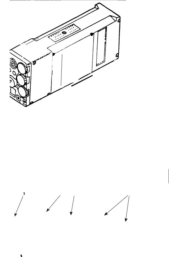
Legend for Figure 1-1:
1.Receiver-Transmitter RT-1695/TRC-199 Unit (A4, A5)
2.Tactical Repeater (TR) Assembly (A1)
3.Weldment, Repeater Frame
4.Power Supply (A2) (includes Power Supply Enclosure and Battery Enclosure)
5.Cable Assembly, TR PS Power (W1)
6.Diplexer Assembly, 30-88 MHz (A3)
7.Diplexer Assembly, 136-174 MHz (A3)
8.Diplexer Assembly, 403-470 MHz (A3)
9.Not Used
10.Antenna, 30-88 MHz
11.Antenna, 136-174 MHz
12.Antenna, 403-470 MHz
13.Antenna, Mast, TR
14.Case, Transceiver Module
15.Strap Assembly, Ground (W5)
16.Strap Assembly, Ground (W6)
17.Strap Assembly, Ground (W7)
18.Rod Assembly, Ground
19.Cable, Coaxial, Antenna (W10)
20.Cable Assembly, TR, 120 VAC, Power (W9)
21.Cable Assembly, TR, 240 VAC, Power (W9)
22.Cable Assembly, TR, 10-32 VDC, Power (W9)
23.Case, Transit, Diplexer
24.Case, Transit, Diplexer
25.Cover, Frame
26.Cable Assembly, Coaxial, RF (W2)
27.Cable Assembly, Coaxial, RF (W3)
28.Cable Assembly, Coaxial, RF (W4)
Figure 1-1. Radio Set AN/TRC-199
(Sheet 1 of 3)
1-0
TO 31R2-2TRC199-1
Figure 1-1. Radio Set AN/TRC-199
(Sheet 2 of 3)
1-1

TO 31R2-2TRC199-1
Figure 1-1. Radio Set AN/TRC-199
(Sheet 3 of 3)
1-2

TO 31R2-2TRC199-1
CHAPTER 1.0 GENERAL INFORMATION
1-1 DESCRIPTION AND PURPOSE.
1-1.1 Equipment Function and Purpose.
Radio Set AN/TRC-199 (hereinafter referred to as the tactical repeater) is a communications unit capable of operating in the 30-88, 136-174, or 403-470 Megahertz (MHz) frequency bands. It is used to extend the communications range of fixed, mobile, or portable receiver-transmitters. The tactical repeater is COMSEC transparent and provides repeater capability for all modes without the need for COMSEC encryption/decryption.
1-1.2 Equipment Description.
(See Figure 1-1.) The tactical repeater includes a tactical repeater assembly, two non-CCI Receiver-Transmitter Sets, Radio RT-1695/TRC-199 (hereinafter referred to as the receiver-transmitters), three antenna systems, an antenna mast, three diplexers, a tubular (weldment) frame, a power supply enclosure, and a battery enclosure.
1-1.2.1 Tactical Repeater Assembly.
(See Figure 7-2.) The tactical repeater assembly includes two circuit card assemblies (CCAs) which are accessible through a removable cover on the underside of the unit. These are the +15 volt (V) DC-DC converter CCA (A1) and repeater control CCA (A3). These CCAs plug into the parent board (A4) which interfaces with control panel assembly (A5), power amplifier assembly (A6), +28V DC-DC converter CCA (A7), the external power supply, and the plug-in receiver-transmitters. The receiver-transmitters plug into sleeves (A8, A9) located on the left and right sides of the front panel of the tactical repeater assembly. The power amplifier (A6) mounts on a heatsink on top of the tactical repeater unit.
1-1.2.2 Receiver-Transmitters.
(See Figure 1-2.) The receiver-transmitters provide transmit/receive communication in the 30-88, 136-174, or 403-470 MHz frequency bands. The operating band of the receiver-transmitters is determined by the transceiver module installed. When the transceiver modules are changed, the tactical repeater must be fitted with the proper antenna and diplexer. The proper configurations are listed in Table 1-1.
Table 1-1. Tactical Repeater Configurations (by Frequency Band)
Frequency Band |
Receiver-Transmitter |
Antenna |
Diplexer |
|
|
|
|
30-88 MHz |
SS-4100820-501 |
4242-MK2-RAC |
SS-1600322-501 |
|
|
|
|
136-174 MHz |
SS-4100821-501 |
4265-RAC |
SS-1600322-502 |
|
|
|
|
403-470 MHz |
SS-4100822-501 |
4266-RAC |
SS-1600322-503 |
|
|
|
|
NOTE
The CCI Receiver-Transmitter RT-1696/U(C) shall not be used in the tactical repeater.
1-1.2.3 Antenna Assembly.
The antenna system for the tactical repeater provides full-duplex transmit and receive capability over one of three bands of operation. The selected antenna is mast mounted. Three antennas are provided to cover the three bands of operation. Refer to Table 1-1. A mast is provided to elevate the selected antenna up to 10 feet (in 5 foot increments) to increase transmission range and quality of transmitted and recorded signals.
Change 1 |
1-3 |
TO 31R2-2TRC199-1
Figure 1-2. Receiver-Transmitter RT-1695/TRC-199
1-1.2.4 Diplexer.
(See Figure 1-3.) The tactical repeater diplexer provides a method of using a receiver and a transmitter on a common antenna. The diplexer, when properly tuned, provides a transmitter-to-receiver isolation of 70 decibels (dB) at any frequency spacing of 4 MHz or 3% of the operating frequency, whichever is greater. The diplexer has an insertion loss of less than 2.25 dB between the transmit port and the antenna and less than 3.0 dB between the receive port and the antenna. The diplexer is capable of handling 60 watts of radio frequency (RF) power in the transmit path and provides protection at the receive port to limit receive signals to a maximum level of +33 power in decibels (referenced to 1 milliwatt) (dBm). There are three separate diplexers, one for each frequency band. The frequency band of the diplexer must correspond to that of the receiver-transmitter and antenna.
Legend for Figure 1-3 (136-174 MHz and 403-470 MHz diplexers have the same controls, but their appearance is slightly
different): |
|
|
|
|
1 Tuning Meter |
2. SENS Control |
3. RCV Control |
4. XMT Control |
5. TUNE Switch |
Figure 1-3. Diplexer Front Panel (30-88 MHz)
1-4 |
Change 1 |
TO 31R2-2TRC199-1
1-1.2.5 Power Supply Assembly.
The power supply assembly provides power for the operation of the tactical repeater. The power supply will operate from any direct current (DC) voltage between 10 and 32 volts and from 120/240 or 220 volts alternating current (VAC). The operation of the power supply is controlled by AC/OFF/DC and internal/external (INT/EXT) DC switches on the power supply. The power supply assembly consists of the power supply enclosure and the battery enclosure.
1-1.2.5.1 Power Supply Enclosure.
The power supply enclosure provides regulated DC power to the tactical repeater assembly.
1-1.2.5.2 Battery Enclosure.
The battery enclosure is a weather-resistant container that can hold either four Lithium batteries (Type BA-5590/U) or four NiCad batteries (Type BB-590/U). The battery connectors are mounted in the bottom of the battery enclosure box. (For battery installation see paragraph 2-10.2.)
1-2 LEADING PARTICULARS.
Leading particulars for the tactical repeater are given in Table 1-2.
|
Table 1-2. Leading Particulars |
|
|
|
|
Characteristic |
|
Parameter |
|
|
|
Equipment dimensions and weight: |
|
|
Length |
|
28.00 inches (in.) (71.1 centimeters (cm)) |
Width |
|
18.50 in. (47.0 cm) |
Height |
|
18.50 in. (47.0 cm) |
Volume |
|
9,583 cubic in. (157,037 cubic cm) |
Weight |
|
130.0 pounds (lbs) (58.97 kilograms (kg)) |
Environmental requirements: |
|
|
Temperature: |
|
-40° Celsius (C) (-40° Fahrenheit (F)) to +49° C (120° F) |
Operating |
|
|
Storage |
|
-51° C (-60° F) to +68° C (155° F) |
Humidity |
|
0 to 95 percent relative humidity |
Electrical power requirements |
|
10V to 32V DC Battery Power |
|
|
120/240 " 10% (1 phase, 3 wire) at 50/60 Hertz (Hz) |
|
|
220 VAC " 10% (1 phase, 3 wire) at 50 Hz |
|
|
|
1-5

TO 31R2-2TRC199-1
1-3 CAPABILITIES AND LIMITATIONS.
Capabilities and limitations of the tactical repeater are given in Table 1-3.
Table 1-3. Capabilities and Limitations
Characteristic |
Parameter |
|
|
Frequency Range (RCV and XMT) |
30-88 MHz |
|
136-174 MHz |
|
403-470 MHz |
Transmitter Output |
2 and 10 watts selectable |
Security |
Tactical repeater is COMSEC transparent |
Interoperability |
AN/PRC-77 Manpack Radio |
|
Radio Set AN/PRC-128 |
|
SINCGARS-V (single channel) |
|
FED-STD-1023 compatible, 12 kbps |
|
VINSON (KY-57) compatible, 16 kbps |
|
Analog 25 MHz frequency modulated (FM) radios |
Receiving/Transmitting |
25 kilohertz (kHz) Bandwidth on all frequency bands. |
|
12.5 kHz intermediate frequency (IF) Bandwidth on 136-174 |
|
MHz and 12.5 kHz channel spacing on 403-470 MHz bands |
|
12.5 kHz tuning steps |
Channels (receive and transmit) |
14 channels each programmable with frequency bandwidth, |
|
output power, and squelch tones (continuous-tone controlled |
|
squelch system (CTCSS)) as variables |
Adjacent Channel Selectivity |
50 dB over 30-88 MHz, 25.0 kHz bandwidth |
|
52 dB over 136-174 MHz, 12.5 kHz bandwidth |
|
60 dB over 136-174 MHz, 25.0 kHz bandwidth |
|
40 dB over 403-470 MHz, 12.5 kHz bandwidth |
|
48 dB over 403-470 MHz, 25.0 kHz bandwidth |
Sensitivity |
-113 dBm or 0.50 V for 12 dB signal + noise + distortion/noise |
|
+ distortion (SINAD) |
Spurious Response and Image Rejection |
65 dB over all bands |
Intermodulation Spurious Response |
60 dB over 30-88 MHz |
|
60 dB over 136-174 MHz |
|
60 dB over 403-470 MHz |
|
|
1-6 |
Change 1 |
TO 31R2-2TRC199-1
1-4 EQUIPMENT SUPPLIED.
Equipment supplied with Radio Set AN/TRC-199 is listed in Table 1-4.
Table 1-4. Equipment Supplied
Official Nomenclature |
Part Number |
Quantity |
|
|
|
Tactical Repeater Assembly |
SS-4100806-501 |
1 |
Power Supply Assembly |
SS-4100733-501 |
1 |
Power Supply Enclosure |
|
|
Battery Enclosure |
|
|
Diplexer Assembly, 30-88 MHz |
SS-1600322-501 |
1 |
Diplexer Assembly, 136-174 MHz |
SS-1600322-502 |
1 |
Diplexer Assembly, 403-470 MHz |
SS-1600322-503 |
1 |
Antenna, 30-88 MHz |
4242-MK2-RAC |
1 |
Antenna 136-174 MHz |
4265-RAC |
1 |
Antenna, 403-470 MHz |
4266-RAC |
1 |
Mast, Antenna Tactical Repeater |
SP10SS |
1 |
Case, Transceiver |
SS-3100552-501 |
1 |
Ground Rod Assembly |
SS-3100551-501 |
1 |
Receiver/Transmitter Set, |
SS-4100807-512 |
2 |
Radio RT-1695/TRC-199 |
SS-4100819-502 |
2 |
Transceiver Module, 30-88 MHz |
SS-4100820-501 |
2 |
Transceiver Module, 136-174 MHz |
SS-4100821-501 |
2 |
Transceiver Module, 403-470 MHz |
SS-4100822-501 |
2 |
Cable Assembly, Tactical Repeater Power |
SS-4500110-501 |
1 |
Cable Assembly, Coaxial, RF |
SS-3500292-501 |
1 |
Cable Assembly, Coaxial, RF |
SS-3500292-502 |
1 |
Cable Assembly, Coaxial, RF |
SS-3500292-503 |
1 |
Strap Assembly, Ground |
SS-3500279-502 |
1 |
Strap Assembly, Ground |
SS-3500279-503 |
1 |
Strap Assembly, Ground |
SS-3500279-504 |
1 |
Cable Assembly, Power Supply, 120 VAC Input |
SS-4500107-501 |
1 |
Cable Assembly, Power Supply, 240 VAC Input |
SS-4500108-501 |
1 |
Cable Assembly, Power Supply, DC |
SS-4500109-501 |
1 |
Cable Assembly, Coaxial, Antenna |
CPRG223/U-30-XX |
1 |
Bumpers, Tactical Repeater Frame |
SS-3400353-1 |
24 |
Bushing, Shock Mount |
SS-2400577-1 |
8 |
Clamp, Rear |
SS-3100546-501 |
1 |
Clamp, Front |
SS-3400355-1 |
1 |
Frame, Weldment |
SS-4400225-1 |
1 |
Case, Transit, Diplexer |
275-160-100-08 |
1 |
Cover, Frame |
IC-3300RC |
1 |
Change 1 |
1-7 |
TO 31R2-2TRC199-1
1-4.1 EQUIPMENT REQUIRED BUT NOT SUPPLIED.
Table 1-5 lists equipment required but not supplied.
Table 1-5. Equipment Required But Not Supplied
Equipment |
Part Number |
|
|
Programmer Unit, Frequency Radio |
SS-4100797-501 |
MX-11531/U |
|
|
|
Batteries |
Lithium Type BA-5590/U |
|
NiCad Type BB-590/U |
|
|
NiCad Battery Charger/Conditioner |
MRC-590 |
|
|
1-5 SPECIAL TOOLS AND TEST EQUIPMENT.
There are no special tools or test equipment required for maintenance.
1-6 RELATED TECHNICAL MANUALS.
Table 1-6 lists related technical manuals.
|
Table 1-6. Related Technical Manuals |
|
|
Publication Number |
Publication Title |
|
|
31R2-2PRC139-1 |
Operation and Maintenance Instructions with Illustrated Parts Breakdown |
|
(Organizational Level) for Radio Set AN/PRC-139(C) (includes |
|
RT-1695/TRC-199, RT-1696/U (C), Programmer Unit, Frequency, Radio |
|
MX-11531/U, Battery Chargers, and Battery Reconditioner) |
31R2-2GRC238-1 |
Operation and Maintenance Instructions with Illustrated Parts Breakdown |
|
(Organizational Level) for Radio Set AN/GRC-238 |
31R2-4-1085-1 |
Operation and Maintenance Instructions with Illustrated Parts Breakdown |
|
(Organizational Level) for Adapter Group OF-228/U |
31R2-2PRC-139-06 |
Work Unit Code Manual |
TO 35C3-2-113-2 |
NiCad Battery Reconditioner, MRC-590 |
|
|
1-8

TO 31R2-2TRC199-1
CHAPTER 2.0 INSTALLATION
2-1 INTRODUCTION.
This section is divided into two sections. Section I. Installation Logistics provides information for site preparation, unloading, unpacking, and inspections, housing, receiving data, material handling, cabling, and buildings and other structures. Section II. Installation Procedures lists tools and equipment required for field installation and describes the installation sequence.
Section I. INSTALLATION LOGISTICS
WARNING
Installation of the tactical repeater requires a minimum of two people.
2-2 SITE PREPARATION.
Select an operating site that is free of obstruction and has access to one of the electrical power sources specified in Table 1-2. The selected operating area must have sufficient room to accommodate the 9583 cubic inch volume of the tactical repeater assembly. The antenna should be at least two antenna lengths (e.g., 44 feet for 30-88 MHz) from power lines and other antennas, etc.
2-3 UNPACKING AND INSPECTIONS.
CAUTION
Exercise care when removing units from packing material in order to prevent damage to the unit.
WARNING
Removing the tactical repeater assembly from the shipping carton requires a minimum of two persons.
To unpack the tactical repeater, remove the unit and any equipment from the carton and store the packing and carton for reuse/shipment. Packing instructions are given in Chapter 3. Inspect contents for completeness, integrity, and damage. Contents shall be in accordance with the packing slips and the list of supplied equipment in Table 1-4.
Refer to Figure 2-1 as a guide in performing the following unpacking procedures:
a.Open top of the fiberboard box (7, Figure 2-1) and remove the polystyrene top piece (2) from box.
b.Remove barrier bag (5) from the box.
c.Remove the tactical repeater assembly (3) from barrier bag (5).
d.Remove packing slip (8) from the plastic envelope on the fiberboard box and check to ensure that all items listed on the packing slip were received.
2-1

TO 31R2-2TRC199-1
|
Legend for Figure 2-1: |
|
|
1 |
Operating instructions |
5. |
Barrier bag |
2. |
Polystyrene top |
6. |
Polystyrene bottom |
3. |
Tactical repeater assembly |
7. |
Fiberboard box |
4. |
Desiccant bag |
8. |
Packing slip |
Figure 2-1. Packaging Diagram for the Tactical Repeater
2-2
TO 31R2-2TRC199-1
e.Store all packing materials (except the desiccant bag) in shipping container and store shipping container for re-use. New desiccant material must be used when repacking.
f.Inspect top and bottom, both sides, and front and rear panels of equipment for dents, scratches or any visually identifiable damage.
g.Inspect controls and indicators on control panel for missing, broken or cracked knobs or levers and note any discrepancies on Receiving Report, DD Form 1348-1. Report any discrepancies in accordance with standard internal receiving procedures.
2-4 HOUSING.
If necessary to store the tactical repeater for any period of time before installation, proceed as follows:
a.Clean the tactical repeater before placing in storage, if necessary. Refer to paragraph 6-3.3.2.
b.Disconnect antennas and accessories before placing the tactical repeater in storage.
c.Remove receiver-transmitters from the tactical repeater before placing in storage.
d.Remove batteries.
NOTE
The temperature of the storage area must be within the range -51° C (-60° F) to +68° C (155° F).
2-5 RECEIVING DATA.
Table 2-1 identifies the contents of the shipping container.
Table 2-1. Tactical Repeater Packaging
|
|
|
Dimensions (in) |
|
Weight |
|
|
|
|
|
|
|
|
Box |
Description |
W |
|
D |
L |
(lb) |
|
|
|
|
|
|
|
1 |
Tactical Repeater Assembly |
34.625 |
|
68 |
33.75 |
195 |
|
|
|
|
|
|
|
2-6 MATERIAL HANDLING.
The weight of the equipment is such that a minimum of two persons are required to lift the equipment.
2-3
TO 31R2-2TRC199-1
2-7 CABLES.
Table 2-2 lists all tactical repeater interconnecting cables.
Table 2-2. Tactical Repeater Interconnecting Cables
Cable |
Cable Part No. |
Description |
Use |
|
Designation |
||||
|
|
|
||
|
|
|
|
|
W1 |
SS-4500110-501 |
Cable Assembly, TR Power |
Connects power supply DC output to |
|
|
|
|
tactical repeater |
|
|
|
|
|
|
W2 |
SS-3500292-501 |
Cable Assembly, Coaxial, RF |
Connects diplexer receiver (RX) output to |
|
|
|
|
tactical repeater assembly |
|
|
|
|
|
|
W3 |
SS-3500292-502 |
Cable Assembly, Coaxial, RF |
Connects diplexer transmitter (TX) output |
|
|
|
|
to tactical repeater assembly |
|
|
|
|
|
|
W4 |
SS-3500292-503 |
Cable Assembly, Coaxial, RF |
Connects diplexer antenna (ANT) output to |
|
|
|
|
RF IN of power supply |
|
|
|
|
|
|
W5 |
SS-3500279-502 |
Strap Assembly, Ground |
Connects tactical repeater assembly to |
|
|
|
|
external ground |
|
|
|
|
|
|
W6 |
SS-3500279-503 |
Strap Assembly, Ground |
Connects diplexer to external ground |
|
|
|
|
|
|
W7 |
SS-3500279-504 |
Strap Assembly, Ground |
Connects power supply to external ground |
|
|
|
|
|
|
W9 |
SS-4500107-501 |
Cable Assembly, Power Supply, |
Connects tactical repeater to 120 VAC |
|
|
|
120 VAC Input |
|
|
|
|
|
|
|
W9 |
SS-4500108-501 |
Cable Assembly, Power Supply, |
Connects tactical repeater to 240 VAC |
|
|
|
240 VAC Input |
|
|
|
|
|
|
|
W9 |
SS-4500109-501 |
Cable Assembly, Power Supply, |
Connects tactical repeater to 10-32 VDC |
|
|
|
DC |
|
|
|
|
|
|
|
W10 |
SS-1600315-1 |
Cable Assembly, Coaxial, |
Connects antenna to antenna connector of |
|
|
|
Antenna |
tactical repeater power supply |
|
|
|
|
|
2-8 BUILDING AND OTHER SUPPORTING STRUCTURES.
Not Applicable.
2-4
TO 31R2-2TRC199-1
Section II. INSTALLATION PROCEDURES
2-9 SPECIAL TOOLS AND EQUIPMENT REQUIRED FOR FIELD INSTALLATION.
No special tools or equipment are needed for installation and initial setup of the tactical repeater.
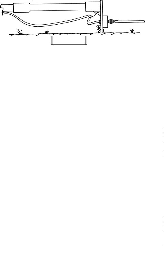
2-10 INSTALLATION SEQUENCE.
(See FO-1.) Perform the following procedure to install the tactical repeater. Cables required for installation are listed in Table 2-2. FO-1 illustrates the required cable connections.
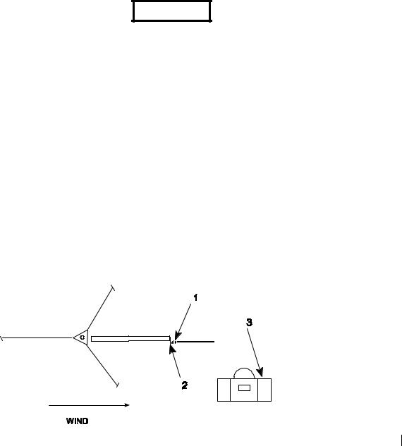
2-10.1 Antenna/Mast Installation.
(Refer to Figure 2-2.) Install the antenna mast and selected antenna as follows:
CAUTION
Ensure proper use of safety tools (work gloves and hard hat) during assembly and disassembly of antenna and mast.
NOTE
The tactical repeater assembly is shipped from the factory configured for 30-88 MHz operation, with the appropriate receiver-transmitters and diplexer. If using a different configuration, substitute the appropriate antenna, receiver-transmitters, and diplexer. Refer to Chapter 6 for antenna and diplexer removal and replacement. Refer to TO 31R2-2PRC139-1 for changing receiver-transmitter configuration.
NOTE
The assembled antenna base section/antenna adapter will fit in the mast transit bag (3) so that step a may be carried out prior to field deployment, if required. When erecting the antennas in high winds, ensure that a minimum of three personnel are used.
a.Bolt the antenna base section (1, Figure 2-2) to the antenna adapter (2) and connect the antenna ground strap to its terminal.
b.Select an unobstructed site. Under windy conditions mast raising is made easier if the mast is laid out on the ground with the base of the mast pointed into wind.
Figure 2-2. Antenna Mast/Antenna Installation (Sheet 1 of 6)
Change 1 |
2-5 |
TO 31R2-2TRC199-1
c.Remove both mast sections from the transit bag (3). Note that the socketed end is the lower end of each section. Place the tubes in line along the ground. Assemble the two tube sections together.
d.Remove the base plate (4), two ground spikes (5), and hammer from the transit bag. Place the base plate at the mast base, arrowhead style, so that the socketed lower end of the mast will engage in the heel. Secure the base plate by driving the two ground spikes through the holes.
WARNING
Before using the hammer, ensure a wedge is placed in the top of the hammer so that the hammer head does not come loose, thereby endangering personnel.
Figure 2-3. Antenna Mast/Antenna Installation (Sheet 2 of 6)
e.Fasten the antenna/adapter assembly to the top antenna section. Connect the top coaxial cable connector to the antenna and attach cable strain relief to hole in web of adapter. Rest flat edge of adapter on ground to provide convenient access to guy rope attachment points. Unwind cable along length of mast and secure to mast at centers of each section. Secure using cable clamps.
Figure 2-4. Antenna Mast/Antenna Installation (Sheet 3 of 6)
f.Remove three guy rope assemblies (6) and three ground anchors (7) from the transit bag. Disconnect the first (fixed) snap hook off the winder and temporarily connect it to the base plate. Carrying the hammer and one of the ground anchors, walk away in the exact opposite direction to the mast (i.e., in the direction that the arrow head is pointing) unwinding the guy rope as you go, until the ground anchor
radius marker is reached. Drive in the ground anchor at this point ensuring that it leans away from the mast (approximately 20o from vertical).
2-6 |
Change 1 |

TO 31R2-2TRC199-1
Figure 2-5. Antenna Mast/Antenna Installation (Sheet 4 of 6)
g.Using the same guy rope as a radius guide, walk across to the approximate location of the second ground anchor. Establish the required 120o from the first ground anchor by using the triangular shape of the base plate as a reference. Drive in a second ground anchor at this point.
Figure 2-6. Antenna Mast/Antenna Installation (Sheet 5 of 6)
h.Repeat step g for the third ground anchor.
i.Disconnect the guy rope used for a radius marker. Attach the fixed (upper) snap hook to the attachment point on the antenna adapter. Attach the running hook at the lower end to ground anchor 2. Note that the winder remains attached to the lower ends of the guy rope to prevent accidental loss.
j.Take a second guy rope. Attach the fixed (upper) snap hook to the antenna adapter attachment point. Attach the running hook at the lower end to ground anchor 3.
k.Attach the upper snap hook of the third guy rope to the adapter attachment point. Unwind the rope along the length of the mast toward the ground anchor 1, but do not attempt to attach the lower end yet. Ensure that guy ropes will not snag coaxial cable when mast is raised.
Change 1 |
2-7 |

TO 31R2-2TRC199-1
l.Ensure foot of mast is securely located in the base plate heel. While person a pushes up mast head Iwo Jima style, person b pulls on guy ropes to raise mast to vertical. Person a should progressively walk towards bottom of mast as it is raised and should hold mast steady as it reaches the vertical. Person b attaches free guy ropes to ground anchor 1 and tightens all ropes.
m.Connect the 30-88 MHz antenna (SS-1600230-1) to the connector at the back of the power supply using the coaxial antenna cable (SS-1600315-1). Refer to FO-1.
Figure 2-7. Antenna Mast/Antenna Installation (Sheet 6 of 6)
2-8 |
Change 1 |
 Loading...