

Page 1
Kinetic In-Line Receiver Switch
Install at ion Ins tr uctions
Self Powered
No Radiation No Maintenance No Wiring
Durable
Cost Saving
Read i nstruct ions carefu lly befor e installation
Specifications
Switch Typ e: P us h button switch
Number of keys: 1 -2 k ey s
Power mode: Sin gl e Li ve L ine Power Supply
Rated Power: 60 0W L ED / ci rcuit
900W other lo ad s* /c ircuit
Worki ng Voltage: 220-24 0V /A C 50 /60Hz
Operating fre qu en cy : 433MHz
Lamp Load Minim um P ow er : 5W
Worki ng Temperature: -2 0 C ~ +55 C
Control dista nc e* *: 8 0m (outdoor) 25 m (i nd oo r)
Control Metho d: P ai ri ng with Quineti c Sw it ch es
● Simply replac e yo ur e xi sting wall switch
with a Quinetic L iv e Li ne s witch
● Combines wall s wi tc h wi th wireless contr ol le r
● Fits into 25mm me ta l/ pl astic patress
● Each switch/c on tr ol ler can pair with a
maximum of 5 auxi li ar y Qu inetic switch es
War ra nty: 3 Years
*Ma ximum l oad rat ing may v ary dep endin g on manu factu rers sp ecifi catio ns.
**D istan ce come s from Qu ineti c labor atory t est res ult. Th e act ual dis tan ce in
pra ctica l use mig ht vary d ue to env ironm ental d iffer enc e.
0 0
Ava il ab le M od el s
1 Gang White
QURS1W
Every Qui ne tic pro du ct has pass ed a s trict q ua li ty insp ec tion
before it l ea ves the f ac tory. Qu in etic pr ov ides 3 year s wa rrant y
if instal le d & used in a cc ordance w it h these i ns tr uctio ns . Within
the 3 years w ar ranty p er iod, Quin et ic will b e re sp onsib le f or the
repair, fr ee r eplac em ent of part s or e ntire p ro du ct.
2 White Gang
QURS2W
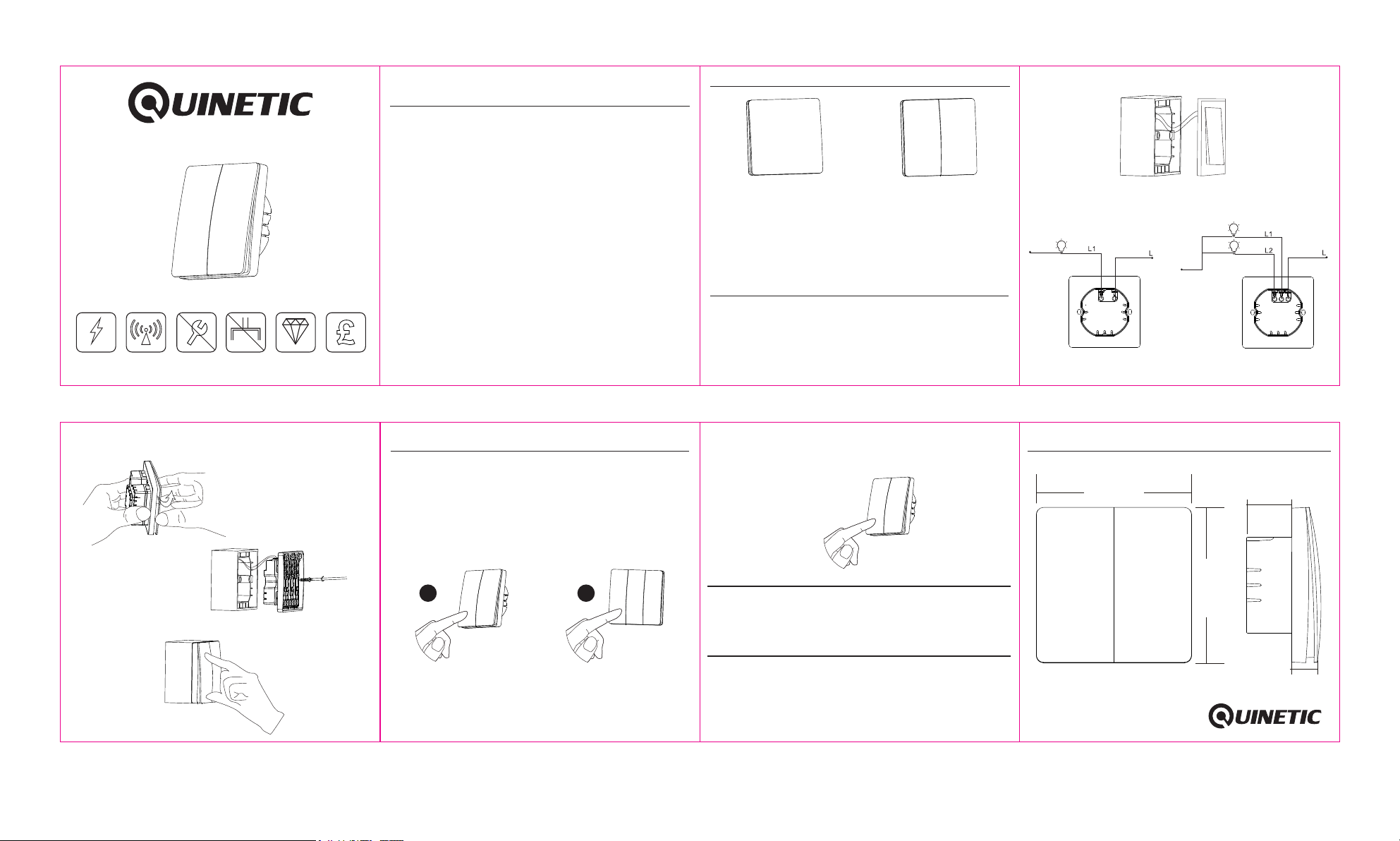
In-Line Receiver Switch Installation
1. Ensure that the power is turned off before installation.
2. The In-Line receiver switch line input should be connected using
only the Live cable from mains.
ATTENTION! - If a neutral line is in situ do not connect it to the In-Line
Switch - this might result in damaging the product! The In-line receiver
switch only works when you have a live feed in and a live feed out.
3. Remove the existing switch from the wall (Fig.1).
Fig.1
4. Disconnect the existing Live in / Live feed out from the existing
wall switch and connect the same to the In-Line receiver switch
as per the wiring diagrams below (Fig.2):
Neutral Line
Live Line
QURS1W QURS2W
Neutral Line
Fig.2
Wiring Diagram
Live Line
5. Carefully open the switch panel as shown in the figure below (Fig.3)
and fix the switch back into place on the wall box.
Fig.3 Carefully open
the switch panel
Fig.4 Fix the switch on the
wall box
6. Press the switch panel back onto the base (Fig.5)
Fig.5
In-Line Receiver Switch Pairing
The Quine ti c In-Li ne S witch pai rs w ith Qui ne ti c wirel es s
switche s fo r dual or m ul tiple con tr ol. A ma ximum o f 5 sw it ches
can be pair ed w ith a In- li ne circui t.
Press and h ol d the swi tc h for 6 secon ds u ntil th e co nn ected
lights st ar t to flas h. R elease th e sw itch - th e li ve l ine swi tc h is
now in pair in g mode. P re ss the wire le ss swit ch b ut ton you w an t
to add to pai r it .
1 2
In-Live Switch
Press and h ol d the swi tc h
6 seconds
Quinetic Wireless switch
Press the w ir eless s wi tch
button on ce t o pair it
with the In -L ine swi tc h
To unpair the a ux iliar y sw itches si mp ly pres s th e sw itch fo r
12 second s un til the l ig hts conne ct ed to the s wi tc h flash 3 t im es
and stop fl as hing. Al l th e pairing i nf ormat io n is n ow clea re d.
Press and h ol d the swi tc h
12 second s to u npair
Precautions
Do not conn ec t the Neu tr al wire to th e In -Line s wi tc h - this
might dam ag e the pro du ct!
Troubleshooting
If the ligh t is w eak or fl as hes conti nu ously a ft er t he swit ch i s
install ed i t means t ha t the lamps /l oad is un de r 5W.
The In-Li ne r eceiv er s witch doe s no t suppo rt l am ps/lo ad s under
5W. Please r ep lace th e la mps with on e of 5 W or abov e.
Dimensions
86.0 0mm
25mm
86.0 0mm
16.6mm
 Loading...