

Page 1
QUCP
Wireless Reccessed & Surface Mounted PIR Sensor Instructions 70*80mm
QUCP
Wireless Recessed & Surface Mounted
PIR Sensor
In st al la ti on I ns tr uc ti on s
Installation
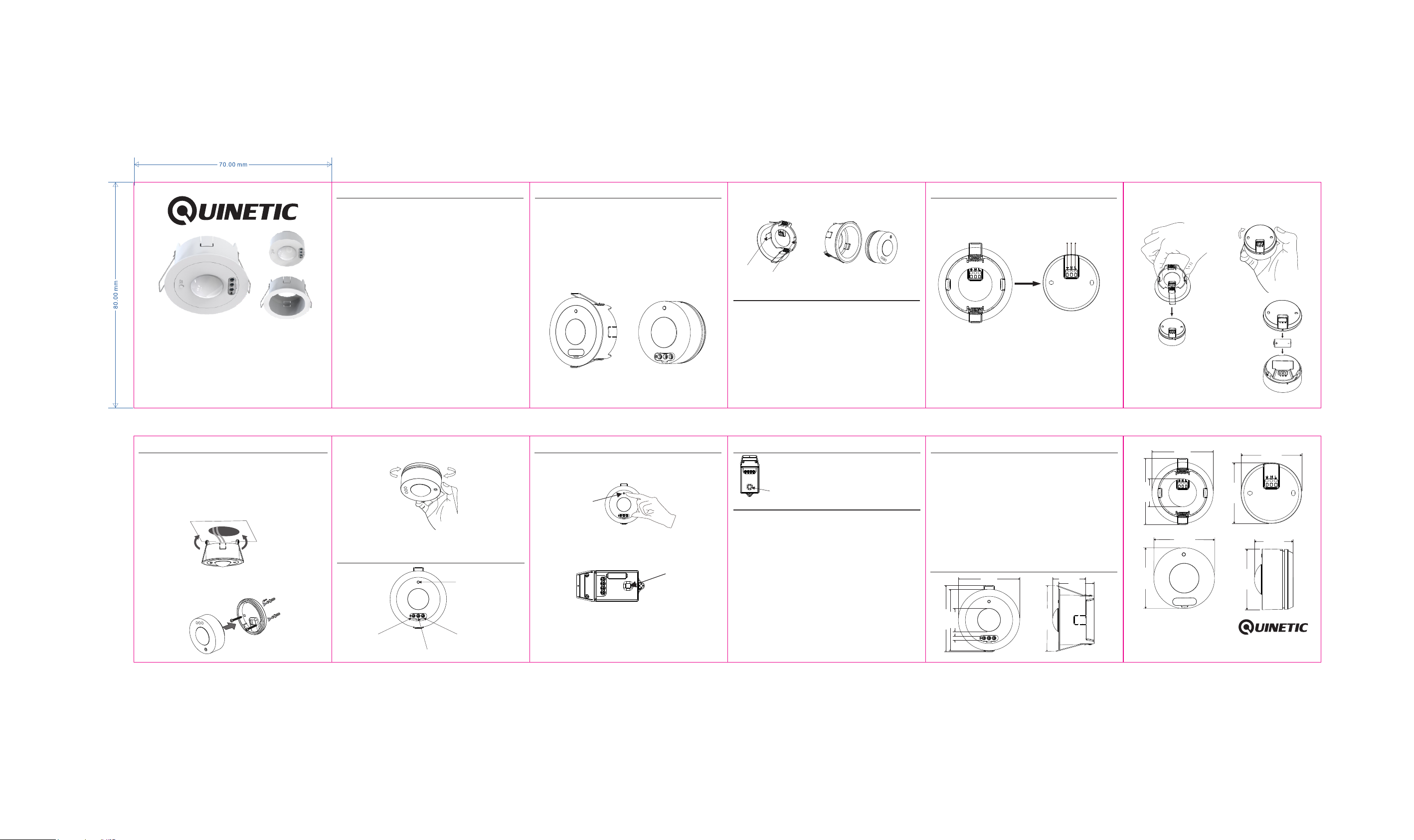
1. Recessed Installation
Cut a 75mm hole in the ceiling ensuring that it does not
infringe with electrical cables, water/gas pipes or ceiling joists.
Connect the mains supply to the PIR and/or install the
CR123A battery.
Push back the positioning springs of the PIR and install it
into the hole in the ceiling. Once the positioning springs are
folded, the PIR is fixed into the ceiling.
2. Surface Mounted
Step 1: Rotate the PIR counter-clockwise and separate it from
the base, then fix the base on the ceiling using the provided
screws.
Spec ificati on s
Switch Type: PIR Sensor
Power Supply: 1 x CR123A Battery (included)
or/and AC 200-240V 50/60Hz
Battery Life: Up to 2 years
Communicating Frequency: RF 433Mhz
Control Distance: up to 30m
Control Method: Pairing with Quinetic Controllers
IP Rating: IP20 (Indoor Use Only)
Detection Range: up to Ø8m
Coverage Area: 30m (324ft ) to 62m (676ft )
Lux Level: 10-2000lux
Detection Angle: 360
Time Range: 3 Seconds to 30 Minutes
Installation Height: 2.4 to 3.6 m (8 to 12 feet)
Installation Method: Recessed Installation (cut-out Ø75mm)
or Surface Mounted
Indicator Light: Green - Pairing/Motion Detection
Red - Low Battery
Operating Temperature: -10 C ~ +50 C
Warranty: 3 Years
2 2 2 2
0
0 0
Read the instru ct io ns carefully be fo re i ns tallation
Step 2: Connect the mains supply to the PIR and/or install the
CR123A battery. Fix the PIR to the base by rotating it
clockwise.
NOTE: For best results fix the sensor on a solid surface
2.4 - 3.6m above ground.
PIR Key Description
Pairing Button
Time
Sensitivity
Lux
Product Description
The QUCP Quinetic ceiling PIR can be installed surface
mounted or recessed. It is powered by a CR123A battery
(included) and can also be powered by an AC 200-240V
power supply.
Once the ceiling PIR is paired with a Quinetic wireless
receiver, it can turn ON the light/load by wireless control after
sensing a person and turn OFF the light/load when the
person leaves the area.
It is suitable for home, classroom, office, warehouse or other
places.
Recessed Installation Surface Mounted
Pairing Method
Step 1: Press and hold the pairing button on the PIR
sensor for 3 seconds; the green LED indicator light will flash
slowly (once per second) and then release the button.
Pairing
Button
Step 2: Press the pairing button on the Quinetic receiver for
3 seconds, the receiver indicator will start flashing slowly
(once every second) and then release the button. The
receiver enters in pairing mode.
Step 3: Press the pairing button on the PIR sensor once;
after the indicator on the receiver stops flashing, the pairing
is successful. The PIR will control the light automatically by
turning it on when a person is detected, and the light will
automatically be turned off when the person leaves the area.
Pairing
Button
The PIR can be separated from the recessed base for
surface mounted installation by pressing the buckles at both
ends of the base to detach it.
Buckles
Detach the Surface Mounted PIR
from the base
Power Supply Instructions
1. The PIR can be powered by 1 x CR123A battery (included)
or/and wired to AC 200-240V power supply.
2. When using both AC 200-240V (wiring method) and
battery power (as a backup power supply), the QUCP
ceiling PIR will use the AC power supply as a priority and
it will not consume the battery.
When the AC 200-240V power supply is disconnected, the
PIR will automatically switch to the battery power supply.
Once the AC 200-240V power supply is restored, it will
automatically switch back to AC and it will no longer
consume the battery.
Clear Pairing
Long press the pairing button on the receiver
for 10-15 seconds (depending on the model),
until the red indicator light goes out.
The pairing with the PIR sensor will be cleared.
Pairing Button
PIR Sensor Adjustments
Remove the silicone cover to access the knobs and use
them to adjust the lux level, the sensitivity and the delay time.
Turn the knobs clockwise to increase the value, or
counter-clockwise to decrease the value.
LUX ADJUSTMENT
LUX is the setting for the ambient light level below which the
PIR sensor will start operating the lights when it senses
movement. Simply set the LUX control knob from night time
(10lux) to daylight (2000lux).
SENSITIVITY ADJUSTMENT
Adjust the control knob clockwise to increase the detecting
range (0 - Ø8m range) or anti-clockwise to decrease the
detecting range.
TIME ADJUSTMENT
Adjust the knob to control how long the light will stay on after
the last movement has been detected. Turn the control knob
clockwise to increase the delay time (up to about 30 minutes)
or anti-clockwise to decrease the time (down to about 3
seconds).
Wiring and Battery Installation
Separate the PIR from the recessed base by pressing the
buckles at both ends to access the AC terminals.
Connect the PIR to an AC 200-240V power supply using the
wiring diagram below:
L: Live Line
N: Neutral Line
E: Earth Line
Installating / Replacing the Battery
To install the CR123A battery or to replace it if the PIR control
becomes insensitive after a period of time or the control
distance becomes much shorter (When the battery level is
under 10% a Red LED indicator will flash quickly) follow the
steps on the next page:
L
E
N
Troubleshooting
1. If the pairing does not work, first check if the indicator
light is lit. Follow the pairing steps to re-pair the sensor.
2. If the sensor does not respond, check the following:
- The battery or AC power supply are present.
- The battery is not low level. If the red indicator light
flashes, replace the battery.
- Make sure that the distance from the sensor to the
Quinetic controller does not exceed the maximum
controlling distance.
- Ensure that the sensor is mounted correctly, facing the
desired detection area.
- Ensure that the Lux level and Sensitivity are set up
correctly.
Product Dimensions
48.9 mm
96.6 mm
52 mm
90 mm
34 mm
96.6 mm
6
90 mm
mm
1. Separate the PIR from the recessed base by pressing the
buckles at both ends (Fig. 1).
2. Turn the PIR counter-clockwise to separate it from the
base and open the battery compartment (Fig. 2).
Fig. 1 Fig. 2
3. Insert the new battery or replace the
existing CR123A Lithium battery (Fig.3).
4. Close the battery compartment by
turning the PIR clockwise.
90 mm
41 mm
96.6 mm
69.1 mm
69.1 mm
*For more informaon about pairing, instrucons and troubleshoot
please visit www.tlc-direct.co.uk website.
69.1 mm
Fig. 3
69.1 mm
44.1 mm
69.1 mm
 Loading...