

Page 1
QURFT Instructions
QURFT
RF Signal Transmitter
Installation Instructions
Read all instructions before installation
Channel Selection Instructions
QURFT RF Transmitter has two RF outputs. Each output can be
independently paired. The transmitter has one Red LED indicator
for channel S1 and one Green LED indicator for channel S2.
Press the pairing button twice to change the channels. The red
or green LED indicator will flash to indicate the channel.
Pairing I ns tructio ns
1. Press the function button on the Quinetic wireless receiver you
want to pair with the RF transmitter for 3 seconds and the
indicator light begins to flash slowly. Release the button to enter
the pairing state.
2. Select the channel on the RF Transmitter and press the function
button to pair. When the indicator light of the Quinetic wireless
receiver goes out the pairing is complete.
3. Press the function button on the RF transmitter to test the signal
transmission to the wireless receiver.
When S1/S2 channel of the RF transmitter receives live line input
it will send an ON signal to control the corresponding wireless
receiver. When the live line is disconnected, an OFF signal is sent.
When the S1 or S2 channel input receives the live line input, the
red indicator light will flash once to indicate successful transmission.
Product D es criptio n
The Qui net ic RF Tr ansmi tte r is a de vic e that se nds a n
RF sign al an d wir eless ly op era tes (ON/OF F) an y Qui netic
recei ver w hen ever vo lta ge is a pplied to it .
it will s end a w ire less si gna l ON to t he receive r whe n eit her
of the S1 /S2 l ive l ines It will s end a n recei ves i npu t signa l.
OFF sig nal t o the w irele ss re cei ver w hen eit her o f the
S1/S2 i npu t lin es Each RF t ran smi tter ca n is disc onn ect ed.
be pair ed wi th mu ltipl e wir ele ss receive rs.
It can be m oun ted i n the cei lin g, wa ll, electr ica l soc ket box ,
lamp pa nel .
Function Button
Bridgin g Mo de
The QURFT RF Transmitter can be used to extend the range of
a wireless kinetic switch to a Quinetic wireless receiver by setting
it in "Bridging Mode".
In order to put the RF transmitter in Bridging Mode press the
pairing button for 3 seconds until the indicator light flashes slowly
and release the button. Press the wireless kinetic switch that
needs to be bridged and the indicator light will go out.
After the pairing is successful press the wireless kinetic switch and
the green indicator on the transmitter will flash once.
The Quinetic wireless receiver needs to be paired with the same
wireless kinetic switch to recognize the bridging mode.
Repeat the same pairing process if another Quinetic receiver and
kinetic wireless switch need to be bridged.
Reverse Ope ration Mo de ( NC)
The RF Transmitter normally open mode (NO) can be reversed
to normally closed mode (NC) as follows:
Double press the pairing button of the RF transmitter to determine
the channel that needs to be reversed through the indicator light.
Specifi ca tions Wiring Di agram & Term inals:
Produ ct Co de: Q URFT
R AC1 50/60 HzVoltag e ange: 00-24 0V
Power S upp ly: N eutra l & Liv e Lin e
Contr ol Di sta nce: m outdo or, 30 m ind oor* 80
, After t he RF t ran smitt er is p air ed wi th the wi rel ess r eceiv er
Commu nic ati on Wa y: RF 4 33M Hz
Capac ity : Can b e paire d wit h an un limited nu mbe r of
Quine tic r ece ivers
Commu nic ati on Chan nel s: Du al Channel
with LE D Ind ica tor s (Red & Gr een )
Wirin g Met hod : Screw Term inals
Signa l Inp ut: 2 C hanne ls Li ve Li ne Input (AC 100 -24 0V)
Stand -by P owe r Consu mpt ion : <1W
Contr ol Me tho d: Th e RF Tra nsmit ter s end s an RF sig nal a nd
wirel ess ly op erate s (ON /OF F) an y Quine tic r ece iver
whene ver v olt age is ap pli ed to i t
Envir onm ent Tem per atu re: -2 °C ~ +5 °CWor king 0 5
Produ ct Si ze: L 44xW4 4xH 22m m
3 Year Wa rra nty
*Distance comes from Quinetic laboratory test results. The actual distance
in practical use might vary due to environmental difference.
Then press the pairing button for 7 seconds until the indicator
light goes from slow flash to on and release the button.
The indicator light will flash 5 times quickly indicating that the
reverse direction is successful.
Once the reverse operation mode is set, when the channel of the
RF transmitter in reversed mode receives the live line input it will
send an OFF signal to control the corresponding Quinetic wireless
receiver. When the live line is disconnected an ON signal is sent.
Clear Pairi ng Inform at ion:
To remove the RF transmitter stored pairing information press the
function button for 10 seconds and the indicator light will flash
slowly, come on then go out. Release the button and the
paired switches signal will be cleared and the bridging mode will
be turned OFF.
: Commu nic ati on Rate 100K bps
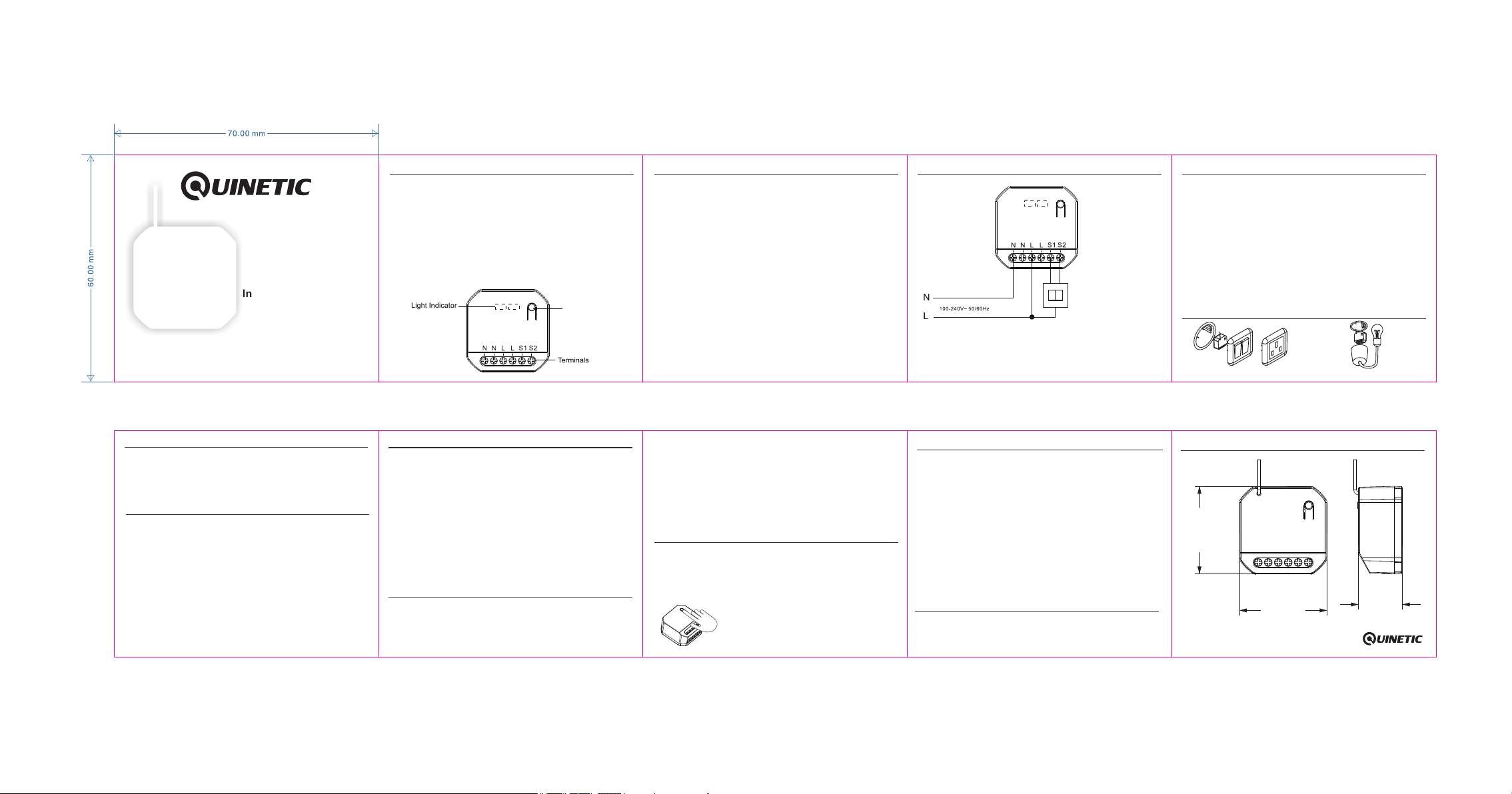
N: Neutral Input terminals
L: Live Input terminals
S1/S2: External Signal terminals
(supports only ON/OFF switching)
Precautio ns:
1. The wiring must be done in accordance with the installation
instructions.
2. Please note the maximum load of an individual controller.
Exceeding this maximum will damage the controller.
3. Do not short-circuit, it will cause permanent damage to the
receiving controller.
4. In there is a power cut the RF transmitter sends an "OFF" signal
to the corresponding Quinetic receiver for safety.
5. When power is restored the RF transmitter will remain in "OFF"
position, reducing fire risk and protecting your appliances.
6. If the contact that operates the S1/S2 input signal remains
closed when the power is restored to the RF transmitter, press
the function button to restore the status of the receiver.
5. Damage caused by incorrect installation and operation are not
covered under warranty.
Troubleshooting:
Press the button for 10 seconds and the light will
flash slowly, come on then go out.
1. If pairing does not work first check if the indicator is lit. Re-pair
in case pairing has been lost after power failure.
2. If the transmitter does not respond check the LED indicator.
If this does not light check the power supply.
Traditional Switch
(or any other equipment
incorporating
NO/NC contacts)
Install at ion
1. Ensure that the power is turned off before installation.
2. The RF Transmitter line input should be connected using live
and neutral cable from mains.
3. Input/signal lines should be connected to a traditional switch or
any other equipment incorporating normally open (NO) /
normally closed contacts.
4. It can be mounted in the ceiling, wall, electrical socket box,
lamp panel.
5. If installed in a ceiling void it is recommended to use a junction
box in order to avoid exposure to electrical terminals.
NOTE:
This device is designed to be used with latching switches/signals
and does not support momentary switches/signals.
Install at ion Locat io ns
Mounted into the switch box or electrical socket Mounted into the ceiling or the lamp panel
Dimensi on s:
44.00 mm
44.00 mm
For more informaon about pairing, instrucons and
troubleshoot please visit www.tlc-direct.co.uk website.
22.00 mm
 Loading...