

Page 1
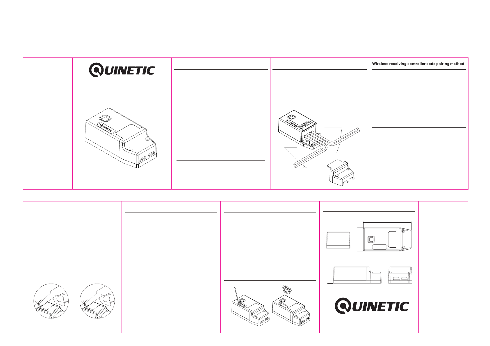
QUR3PM
6A Momentary Controller Instructions 80*60mm
Momentary Controller
for Quinetic Wireless Switch
Installation Instructions
QUR3PM
Read all instructions before installation
4. Single, double and triple switches follow the same
pairing method.
5. In order to put the controller in to Bridging mode
press the function button for 7 seconds. The
indicator light will pulse continuously to indicated
a successful "bridge".
6. If the controller indicator light continues to pulse
the controller will still function normally even if
used with a single switch.
7. To remove the controller stored pairing information
press function button for 10 seconds until the
indicator light goes out - the pairing information
will be removed.
Specifications
Mo me nt ar y Controlle r fo r Qu in etic
Wire le ss S wi tch
Technic al S pe ci fications :
Produ ct C ode : QU R3PM
Voltag e ra nge : 85 -260V 5 0/60H z
Wor ki ng en vi ronme nt temp er atu re : -25°C ~ + 50°C
Contr ol d ist an ce*: 80 m(out do or) , 30 m(ind oor)
Capac it y: Up t o 10 s witch es can be p ai red w it h
one con troll er
Contr ol m eth od : pairi ng with D im mab le Q uinet ic
Wirel ess Swi tc h
QUR3P M Mo men ta ry Cont rolle r re mai n ac tive
as long a s th e pai re d switc h is pres se d.
The pow er t urn s OF F once th e user st op s pre ss ing
the swi tc h.
Contr ol Lo ad: 6A
Maxim um Lo ad: 500 W LED
1100 W oth er load s**
*Distance comes from Quinetic laboratory test results.
The actual distance in practical use might vary due to
environmental difference.
**Maximum load rating may vary depending on
manufacturers specifications.
Precautions:
1. The momentary receiving controller works only
with dimmable Quinetic switches (push type).
2. The wiring must be done in accordance with the
method of installation illustrated.
3. Please note the maximum loading of an individual
controller. Exceeding this maximum will result in
blowing the fuse.
4. Do not short-circuit, otherwise it will cause
permanent damage to the receiving controller.
5. The controller will remain "OFF" after a power cut,
saving energy, reducing fire risk and protecting
your appliances.
6. Damage caused by incorrect installation and
operation are not covered under warranty.
Wireless rece iv in g co nt ro ller installation
1. Ensure that the power is turned off before installation.
2. The wireless receiver/controller line input should be
connected using live and neutral cable from mains.
3. Output lines should be connected to load using cable
rating suitable for 85-260V depending on voltage at
site. (see diagram below).
4. Use the double-sided adhesive tape or screw to fix the
wireless receiving controller.
Wiring Instructions
Live In
Neutral In
Troubleshooting:
1. If pairing does not work first check if the indicator is lit.
Re-pair in case the pair is lost after power failure.
2. If the receiver does not respond check the LED
indicator. If this does not light check the power supply,
if present the fuse may need replacing(see below)
- Turn power off and remove fuse as shown below.
- Replace with a fuse of the same specification and
put it back in the controller.
- Turn the power back on and press the function button
to check LED lights.
- Replacing the fuse does not affect the original pairing
setting.
Replacing the fuse:
Live Out
Neutral Out
Dimensions:
30.9mm
Wireless Quinetic energy switch and wireless
receiving controller can be paired with any
combination: a controller can be controlled by a
maximum of 10 separate switches, a switch can
be paired with an unlimited number of controllers.
The range of a switch may also be extended by
putting the controller into the "Bridging Mode".
Code pairing steps:
1. Press the function button for 3 seconds and the
indicator light begins to flash slowly. Then release
the button and enter the single pairing state.
2. Press the wireless kinetic energy switch and the
indicator light of the controller will go out, which
means that the pairing is successful.
3. If you need to add more switches to the same
controller, please repeat the above process;
each controller can store up to 10 switches,
pairing in formation.
88.8mm
43.7mm
Press for 3 seconds to enter
program mode
Press for 10 seconds to
clear memory
*Please note: For more pairing information visit www.tlc-direct.co.uk
 Loading...