

Page 1
QUGDCL
Wireless Grid Switch Instructions 80*60mm
QUGDCL
Wireless SwitchGrid
Scolmore Mi niGrid Faceplate Compat ible *
Installation Instructions
Self Powered
No Radiation No Maintenance No Wiring
*co mpati ble - mea ns that th ese pro ducts w ill fit in to the Sc olmor e facep late.
Scol more do es not su pply o r endor se or pro vide an y suppo rt for the se pro ducts.
"Sco lmore " and "Mi niGri d" are ac know ledge d as trad emark s of The Sco lmore G roup.
Wireless Grid Switch Operation:
The Quinetic wireless grid switch is Scolmore MiniGrid
faceplate compatible* with the Minigrid system and
It can be used with the standard or with the dimming
Quinetic receiving controller (see controller instructions
for more details about pairing).
Dimming Operation:
When paired with dimming Quinetic receiving controllers
the grid switch can also dim the lights:
Pressing the switch quickly will turn the light ON/OFF.
Keep the switch pressed to dim the light to the desired
level.
While the switch is pressed the lights will go down
from 100%-0% and they will go up from 0-100%
cyclically.
Quinetic Switch and Controller Wireless System:
The wireless Quinetic grid switch and wireless
receiving controller can be paired in any combination:
a controller can be controlled by a maximum of
10 separate switches, a switch can pair with an
unlimited number of controllers.
*co mpatib le - mean s that th ese pro ducts w ill fit in to the Sc olmor e facep late.
Scol more do es not su pply o r endor se or pro vide an y suppo rt for th ese pro ducts .
"Sco lmore " and "Mi niGri d" are ac knowl edge d as trad emark s of The Sco lmore G roup.
Click Minigrid mounting can be installed into plates.
Read instructions carefully before installation
Wireless Grid Switch
Durable
Cost Saving
Installation Instructions:
1. Ensure the mounting box is securely fixed to the wall.
2. The Quinetic Click Scolmore Minigrid switch module
is easily and quickly mounted onto Click Minigrid
plates using screws for fixing (Fig.1).
3. Ensure no conductors into the mounting box are
pinched or trapped.
4. If necessary the modules can be removed by
unscrewing them out from the grid plate .
5. Place the front plate over the assembly and secure it
with the screws provided (Fig.2). Do not over tighten
the screws, to do so may damage the front plate,
fixing screws or grid frame.
Fig.1
Fig.2
QUGDCL
Specifications
Wireless Grid Switch Technical Parameters:
Work Type: Push Button
Power Source: Micro energy acquisition and self
generating (no battery required)
Number of Keys: 1 (1 gang)
Control Distance: 25m (indoor)
Communication Model: FSK
Work Frequency: 433Hz
Work Environment Temperature: -20 C ~ 55 C
Control Method: Pairing with Quinetic Wireless Controller
Life Time: ≥100000 times
3 Year Warranty
Dis tance c omes fro m Quine tic lab orato ry test r esult . The act ual dis tance i n pract ical
use m ight va ry due to e nviro nment al diffe rence .
NOTE : The gri d metal p late or c over mi ght red uce the c ontro l dista nce, as t he meta l
wil l cause e lectr omagn etic sh ieldi ng that b locks t he RF sig nal.
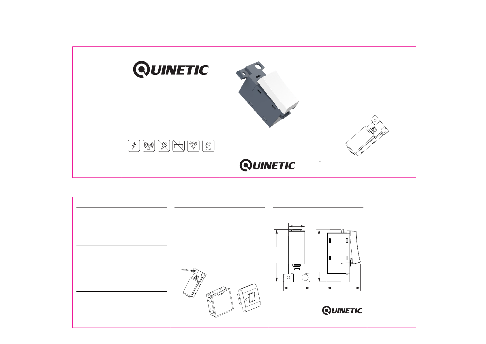
Product dimensions:
15.80 mm
49.50 mm
25.30 mm
*For more informaon about pairing, instrucons and troubleshoot
please visit www.tlc-direct.co.uk website.
49.50 mm
31.88 mm
0 0
 Loading...