

Page 1
QUA313 Instructions
Qui netic W ireles s Socket A dapto r
Installation Instructions
QUA313
Read all instructions before installation
Qui neti c Wir eles s Soc ket Ada ptor
Tech nic al Spe cif icat ion s:
Inp ut Volta ge: 85- 260V 50 /60Hz
Out put Volt age: 85 -260V 5 0/60H z
Wor king en viron ment te mpera ture: - 25°C - 50 °C
Con trol di stanc e*: 20m (indo or)
Con trol me thod: p airin g with Qu ineti c Wirel ess
Swi tch (se e instr uctio ns)
Con trol Loa d: 13A
Max imum Loa d: 1000 W LED & 3kW ot her loa ds**
*Distance comes from Quinetic laboratory test results.
The actual distance in practical use might vary due to
environmental difference.
**Maximum load rating may vary depending on
manufacturers specifications.
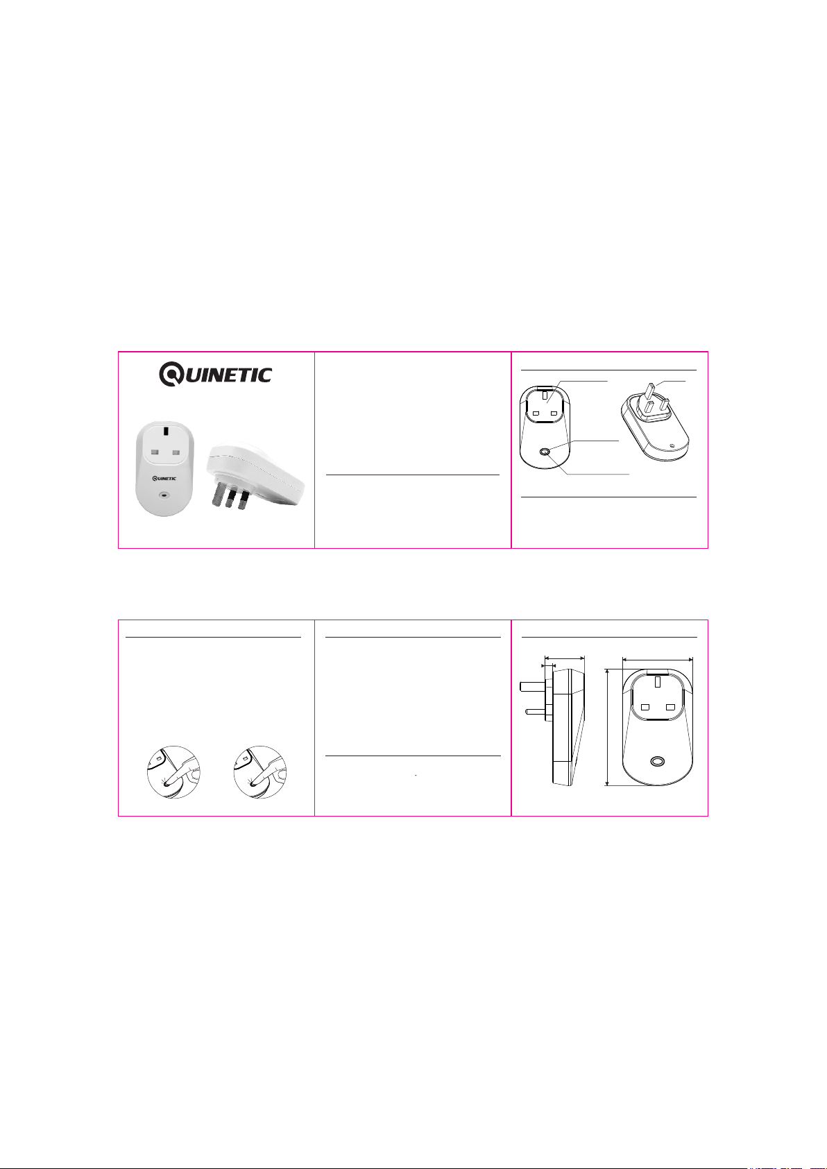
Ide ntif ica tion o f Par ts:
Soc ket to t ake
13A pl ug
Pai ring B utton
Man ual Sw itch
Plu g
LED I ndic ator Li ght
Qui neti c Wir eles s Soc ket Ada ptor co nfig ura tion
1. Plug the Quinetic Wireless socket adapter into a wall outlet.
2. The sockets can be manually switched or controlled by the
wireless Quinetic energy switch.
3. For manual operation push the manual Switch button. The
socket is ON when the LED indicator light is RED.
Wire less so cket ad aptor pa iring m ethod *:
The wireless Quinetic energy switch and wireless socket adaptor can be paired with
any combination: an adaptor can be controlled by a maximum of 10 separate
switches, a switch can pair with an unlimited number of socket adaptors. The range
of a switch may also be extended by putting the adaptor into the " Bridging Mode".
Code pairing steps:
1. Press the function button for 3 seconds and the indicator light begins to flash
slowly. Then release the button and enter the single pairing state.
2. Press the wireless kinetic energy switch and the indicator light of the socket
adaptor will go out, which means that the pairing is successful.
3. If you need to add more switches to the same adaptor, please repeat the above
process; each adaptor can store up to 10 switches, pairing in formation.
4. Single, double and triple switches follow the same pairing method.
5. In order to put the controller in to Bridging mode press the function button for 7
seconds. The indicator light will pulse continuously to indicated a succesful "bridge".
6. If the controller indicator light continues to pulse the controller will still function
normally even if used with a single switch.
7. To remove the adaptor stored pairing information press function button for 10
seconds until the indicator light goes out - the pairing information will be removed.
Press for 3 seconds to enter
program mode
Press for 10 seconds to
clear memory
Prec autio ns:
1. To prevent injury, the socket adaptor must be securely plugged in
to a 13 Amp wall socket.
2. Please note the maximum loading of an individual controller.
Exceeding this maximum will result in blowing the fuse (non
replaceable).
3. Do not short-circuit, otherwise it will cause permanent damage
to the socket adapter.
3. The socket will remain "OFF" after a power cut, saving energy,
reducing fire risk and protecting your appliances.
4. For indoor use only.
5. Please use the socket in dry place; it must not be used in a
bathroom or other damp locations.
6. Damage caused by incorrect installation and operation are
not covered under warranty.
Troub lesho oting :
1. If pairing does not work first check if the indicator is lit.
Re-pair in case the pair is lost after power failure.
2. If the receiver does not respond check the LED indicator.
If this does not light check the wall outlet and refer back to
supplier.
Qui netic W ireles s Socket A dapto r Dimen sions :
34.5mm
6.5mm
103mm
*Please note: For more pairing information visit www.tlc-direct.co.uk
62mm
 Loading...