

Page 1
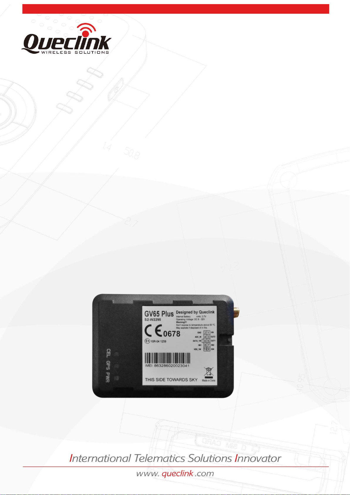
GV55 User manual
GSM/GPRS/GPS Tracker GV65 Plus
TRACGV65PUM001
Revision:1.01
User Manual
TRACGV3SUM001 - 0 -
Page 2
GV65 Plus User Manual
Queclink
Confidential
Document Title
Version
Date
Status
Document Control ID
General Notes
Queclink offers this information as a service to its customers, to support application and
engineering efforts that use the products designed by Queclink. The information provided is
based upon requirements specifically provided to Queclink by the customers. Queclink has not
undertaken any independent search for additional relevant information, including any
information that may be in the customer’s possession. Furthermore, system validation of this
product designed by Queclink within a larger electronic system remains the responsibility of the
customer or the customer’s system integrator. All specifications supplied herein are subject to
change.
Copyright
This document contains proprietary technical information which is the property of Queclink.
Copying of this document and giving it to others and the using or communication of the contents
thereof, are forbidden without express authority. Offenders are liable to the payment of
damages. All rights reserved in the event of grant of a patent or the registration of a utility model
or design. All specifications supplied herein are subject to change without notice at any time.
Copyright © Queclink Wireless Solutions Co., Ltd. 2014
GV65 Plus User Manual
1.01
2015-1-23
Release
TRACGV65PUM001
TRACGV65PUM001 - 1 -
Page 3

GV65 Plus User Manual
Queclink
Confidential
Contents
GSM/GPRS/GPS Tracker GV65 Plus ........................................................................................ 0
TRACGV65PUM001 ........................................................................................................................... 0
Revision:1.01 ..................................................................................................................................... 0
User Manual .................................................................................................................................... 0
Contents ............................................................................................................................................ 2
0 Revision History .............................................................................................................................. 5
1 Introduction ................................................................................................................................... 6
1.1. Reference ............................................................................................................................. 6
1.2. Terms and Abbreviations ..................................................................................................... 6
2 Product Overview ........................................................................................................................... 7
2.1. Check Parts List .................................................................................................................... 7
2.2. Parts List .............................................................................................................................. 8
2.3. Interface Definition ............................................................................................................. 8
2.4. GV65 Plus User Cable Colour ............................................................................................... 9
3 Get Started ................................................................................................................................... 10
3.1. Open the Case ................................................................................................................... 10
3.2. Close the Case ................................................................................................................... 10
3.3. Install a SIM Card ............................................................................................................... 11
3.4. The Internal Backup Battery .............................................................................................. 11
3.5. Switch ON/OFF the Internal Backup Battery ..................................................................... 12
3.6. Install the External GPS Antenna (Optional) ...................................................................... 12
3.7. Power Connection ............................................................................................................. 13
3.8. Ignition Detection .............................................................................................................. 13
3.9. Digital Inputs ..................................................................................................................... 14
3.10. Analog Inputs .................................................................................................................. 15
3.11. Digital Outputs
3.12. Device Status LED ............................................................................................................ 17
3.13. 1-wire Device Connection ............................................................................................... 19
3.14. Motion Sensor Direction ................................................................................................. 21
................................................................................ 15
................................
TRACGV65PUM001 - 2 -
Page 4

GV65 Plus User Manual
Queclink
Confidential
Table Index
TAB L E 1. GV65 PLUS PROTOCOL REFERENCE ................................................................................. 6
TAB L E 2. TERMS AND ABBREVIATIONS........................................................................................... 6
TAB L E 3. PART S L I ST ........................................................................................................................ 8
TAB L E 4. DESCRIPTION OF 10 PIN CONNECTIONS.......................................................................... 9
TAB L E 5. GV65 PLUS USER CABLE COLOUR DEFINITION ................................................................ 9
TAB L E 6. GPS ANTENNA SPECIFICATION ....................................................................................... 13
TAB L E 7.
TAB L E 8.
TAB L E 9.
TABLE 10.
ELECTRICAL CHARACTERISTICS OF IGNITION DETECTION ............................................. 13
ELECTRICAL CHARACTERISTICS OF THE DIGITAL INPUTS ............................................... 14
ELECTRICAL CHARACTERISTICS OF DIGITAL OUTPUTS ................................................... 16
DEFINITION OF DEVICE STATUS AND LED ...................................................................... 19
TRACGV65PUM001 - 3 -
Page 5

GV65 Plus User Manual
Queclink
Confidential
Figure Index
FIGURE 1. APPEARANCE OF GV65 PLUS ........................................................................................... 7
FIGURE 2.
FIGURE 3.
FIGURE 4.
FIGURE 5.
FIGURE 6.
FIGURE 7.
FIGURE 8.
FIGURE 9.
FIGURE 10.
FIGURE 11.
FIGURE 12.
FIGURE 13.
FIGURE 14.
FIGURE 15.
FIGURE 16.
FIGURE 17.
FIGURE 18.
FIGURE 19.
THE 10 PIN CONNECTOR ON THE GV65 PLUS .................................................................. 8
OPEN THE CASE ............................................................................................................. 10
CLOSE THE CASE ............................................................................................................ 10
SIM CARD INSTALLATION ............................................................................................... 11
INTERNAL BACKUP BATTERY .......................................................................................... 11
THE EXTERNAL GPS ANTENNA OF GV65 PLUS ............................................................... 12
TYPICAL POWER CONNECTION ...................................................................................... 13
TYPICAL IGNITION DETECTION ...................................................................................... 14
TYPICAL DIGITAL INPUT CONNECTION ........................................................................... 15
TYPICAL DIGITAL INPUT CONNECTION ........................................................................... 15
DIGITAL OUTPUT INTERNAL DRIVE CIRCUIT .................................................................. 16
TYPICAL CONNECTION WITH REL AY .............................................................................. 16
TYPICAL CONNECTION WITH LED .................................................................................. 17
GV65 PLUS LED ON THE CASE ........................................................................................ 18
TYPICAL CONNECTION WITH 1-WIRE DEVICE ................................................................ 20
TYPICAL CONNECTION WITH IBUTTON READER ............................................................ 20
TYPICAL CONNECTION WITH TEMPERATURE SENSOR .................................................. 21
MOTION SENSOR DIRECTION ........................................................................................ 22
TRACGV65PUM001 - 4 -
Page 6
GV65 Plus User Manual
Queclink
Confidential
0 Revision History
Revision Date Author Description of change
1.00 2014-12-17 Lulu Gao
World Chu
Richard Deng
Pam Pan
1.01
2015-01-23 World.Chu Add acc sensor xyz description
Initial
TRACGV65PUM001 - 5 -
Page 7
GV65 Plus User Manual
The air protocol interface between
Queclink
Confidential
1. Introduction
The GV65 Plus is a powerful GPS locator designed for vehicle or asset tracking. It has superior
receiving sensitivity, fast TTFF (Time to First Fix) and supports quad-band GSM frequencies
850/900/1800/1900. Its location can be monitored in real time or periodically tracked by a
backend server or other specified terminals. The GV65 Plus has multiple input/output interfaces
that can be used for monitoring or controlling external devices. Based on the integrated @Track
protocol, the GV65 Plus can communicate with a backend server through the GPRS/GSM
network to transfer reports of emergency, geo-fence boundary crossings, scheduled GPS position
and many other useful reporting features. Users can also use GV65 Plus to monitor the status of
a vehicle and control the vehicle by its external relay output. System integrators can easily set up
their tracking systems based on the full-featured @Track protocol.
1.1. Reference
Table 1. GV65 Plus Protocol Reference
SN Document name Remark
[1] GV65 Plus @Track Air Interface Protocol
GV65 Plus and backend server.
1.2. Terms and Abbreviations
Table 2. Terms and Abbreviations
Abbreviation Description
AGND Analog Ground
AIN Analog Input
DIN Digital Input
DOUT Digital Output
GND Ground
MIC Microphone
RXD Receive Data
TXD Transmit Data
SPKN Speaker Negative
SPKP Speaker Positive
TRACGV65PUM001 - 6 -
Page 8
GV65 Plus User Manual
Check Parts List
Queclink
Confidential
2 Product Overview
2.1.
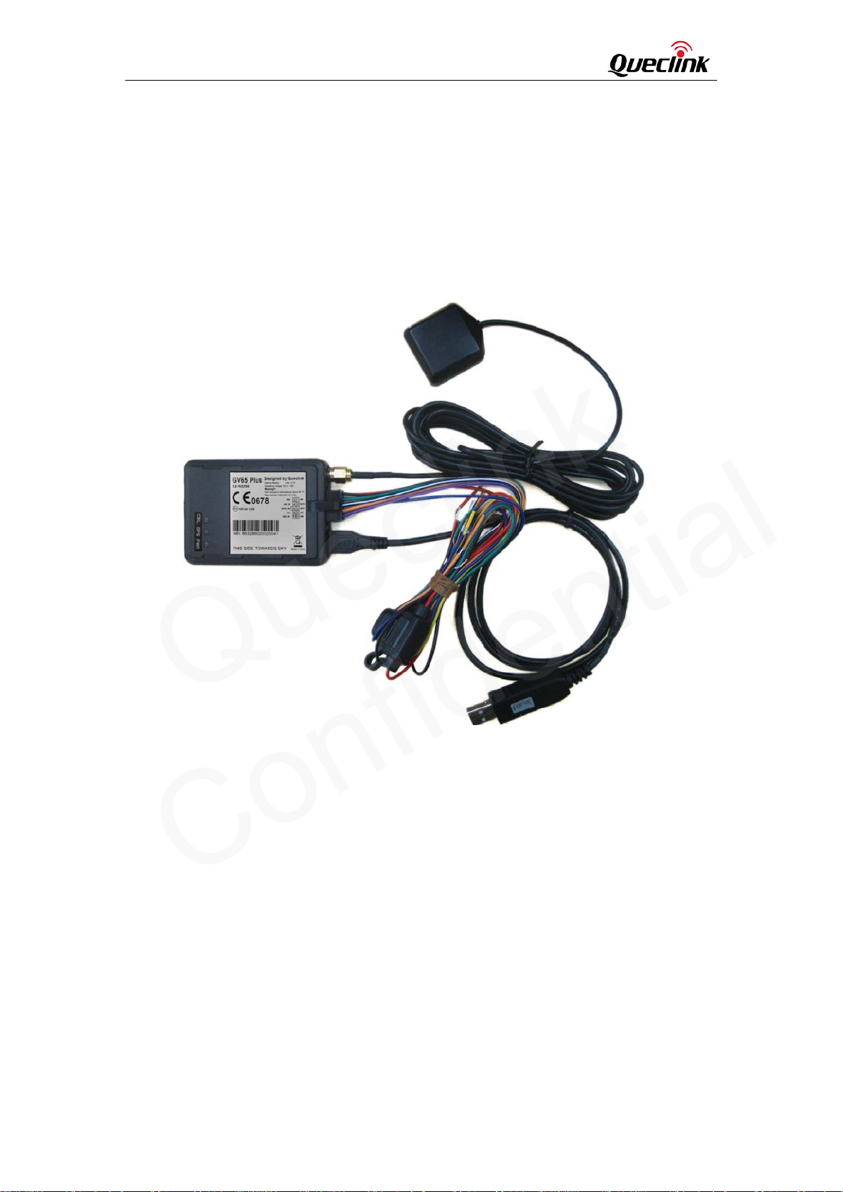
Before starting, check whether all the following items have been included with your GV65 Plus. If
anything is missing, please contact your supplier.
Figure 1. Appearance of GV65 Plus
TRACGV65PUM001 - 7 -
Page 9
GV65 Plus User Manual
Queclink
Confidential
2.2. Parts List
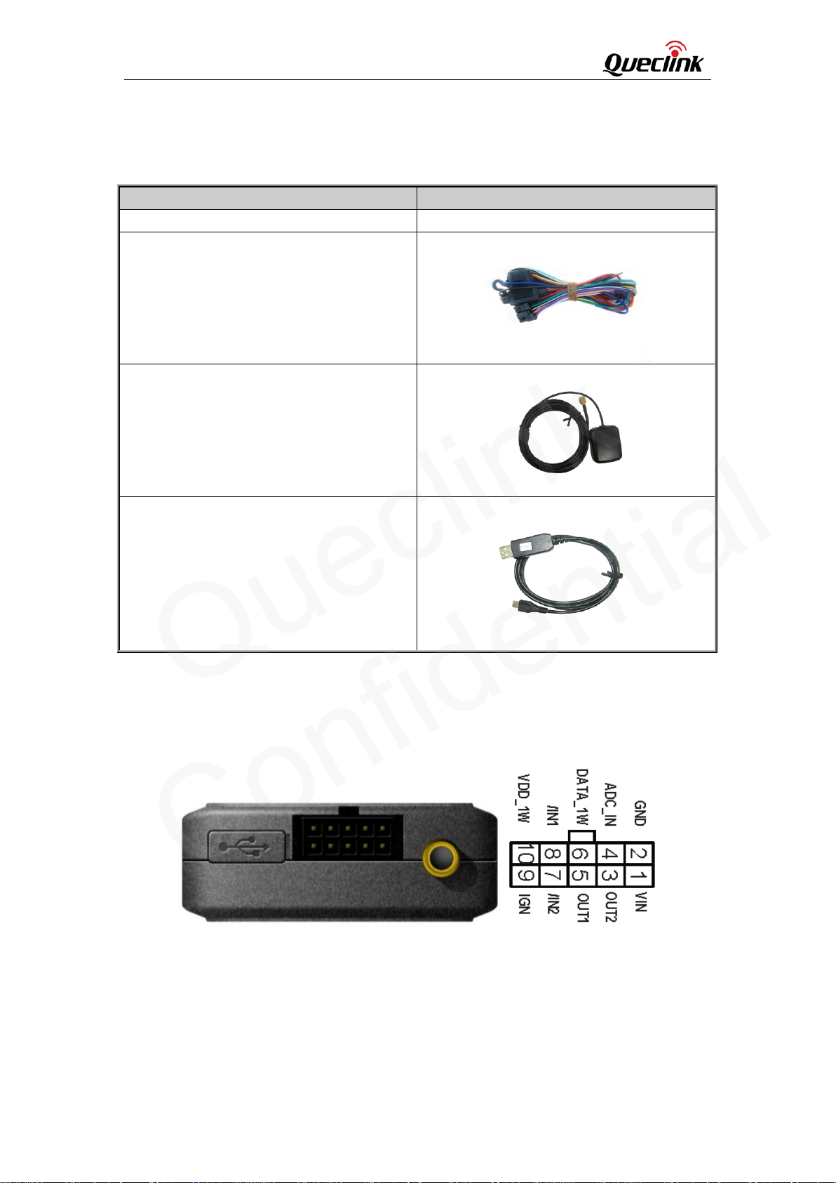
Table 3. Parts List
Name Picture
GV65 Plus Locator 73mm*54mm*22.7mm
User Cable
GPS Antenna (Optional)
DATA_CABLE_M (Optional)
2.3. Interface Definition
The GV65 Plus has a 10 PIN interface connector. It contains the connections for power, I/O, etc.
The sequence and definition of the 10PIN connector are shown in the following figure:
Figure 2. The 10 PIN Connector on the GV65 Plus
TRACGV65PUM001 - 8 -
Page 10
GV65 Plus User Manual
User Cable Colour
Queclink
Confidential
Table 4. Description of 10 PIN Connections
Index Description Comment
1
2
VIN External DC power input, 8-32V
GND GND
3
4
5
6
7
8
9
10
2.4. GV65 Plus
Definition
GND Black 2
ADC_IN Green 4 3 Yellow OUT2
OUT2 Open drain, 150 mA max
ADC_IN Fuel ADC input
OUT1 Open drain, 150 mA max ,with latch circuit
DATA_1W 1-wire data bus
/IN2 Digital input, negative trigger
/IN1 Digital input, negative trigger
IGN Ignition input, positive trigger
VDD_1W 1-wire device power output
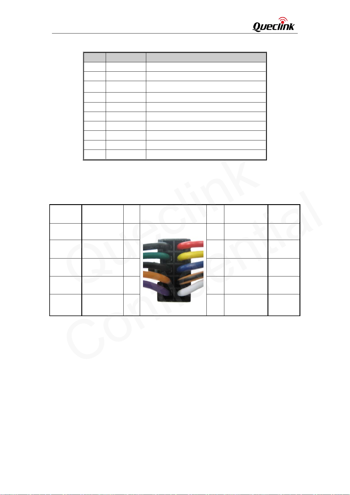
Table 5. GV65 Plus User Cable Colour Definition
Colour
PIN
No.
Cable
PIN
No.
1 Red VIN
Colour
Definition
DATA_1W White/Black 6 5 Blue OUT1
/IN1 Orange 8 7 Orange/Black /IN2
VDD_1W Purple 10 9 White IGN
TRACGV65PUM001 - 9 -
Page 11
GV65 Plus User Manual
Queclink
Confidential
3 Get Started
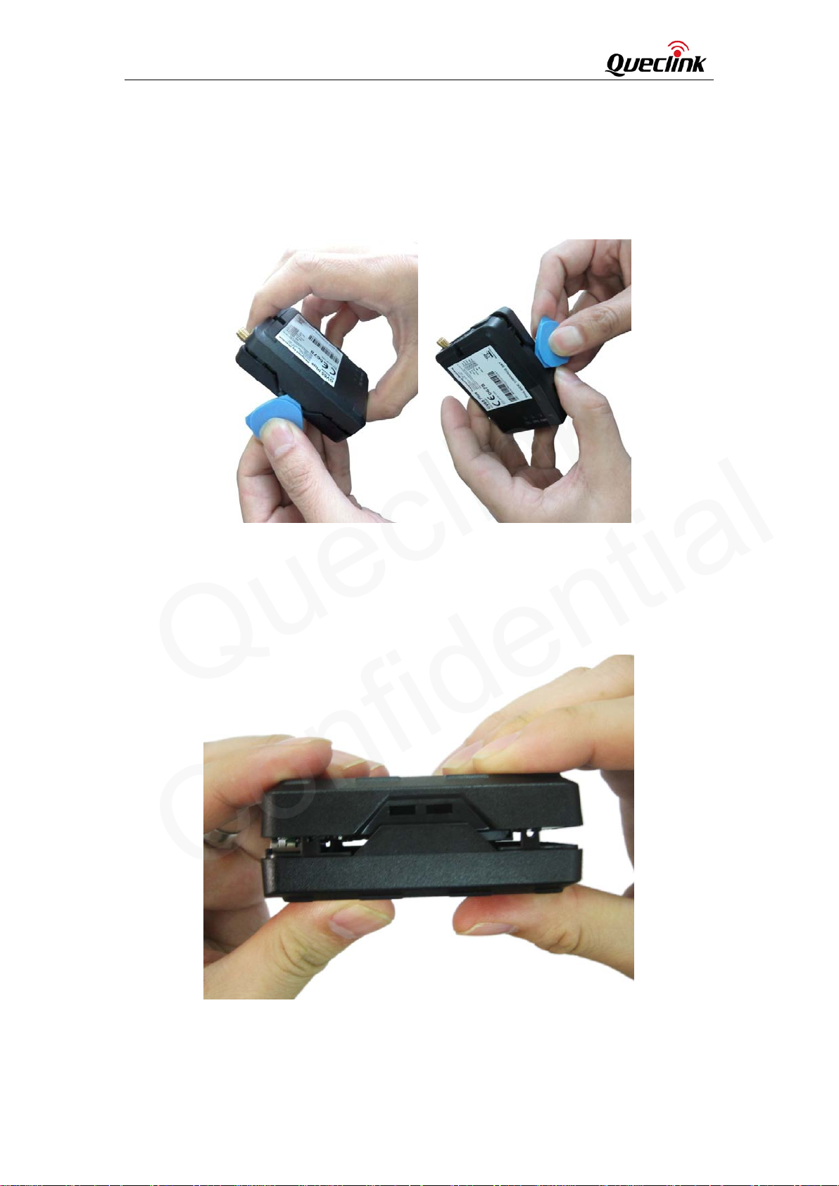
3.1. Open the Case
Figure 3. Open the Case
Insert the triangular-pry-opener into the gap on both sides of the case as shown above, and push
the opener up until the case is unsnapped.
3.2. Close the Case
Figure 4. Close the Case
Place the cover on the bottom in the position as shown in the figure above. Press the front case
and the back case until it snaps.
TRACGV65PUM001 - 10 -
Page 12
GV65 Plus User Manual
ard
Queclink
Confidential
3.3. Install a SIM C
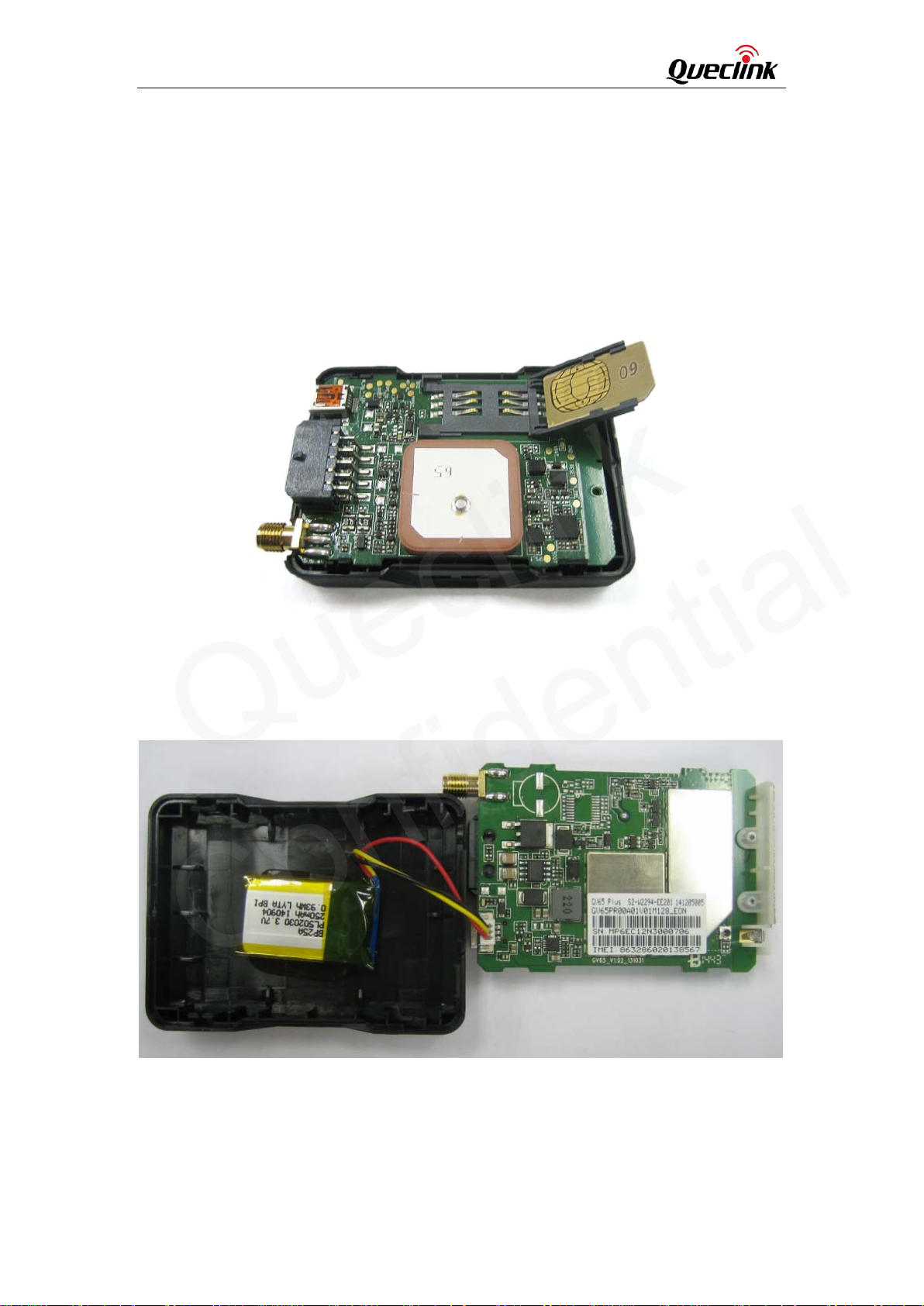
Open the case and ensure the unit is not powered (unplug the 10Pin cable). Slide the holder right
to open the SIM card. Insert the SIM card into the holder as shown below with the gold-colored
contact area facing down. Take care to align the cut mark. Close the SIM card holder. Close the
case.
Figure 5. SIM Card Installation
3.4. The Internal Backup Battery
There is an internal backup Li-ion battery,
Figure 6. Internal Backup Battery
TRACGV65PUM001 - 11 -
Page 13
GV65 Plus User Manual
the External GPS Antenna (Optional)
Queclink
Confidential
3.5. Switch ON/OFF the Internal Backup Battery
The control bit of Backup Battery Switch in GTCFG is designed to control whether the backup
battery of GV65 Plus is working. As to the detailed explanation of GTCFG command, please refer
to related content in ”GV65 Plus @Track Air Interface Protocol”.
<Backup Battery Switch>: Control to switch on/off the backup battery.
l 0: switch off the backup battery.
l 1: switch on the backup battery.
<Backup Battery Charge Mode>: Control the charge mode of the backup battery.
l 0: When the main power supply is connected, charge the backup battery
on need.
l 1: When the main power supply is connected, only charge the backup
battery when ignition on is detected. The charge process will begin 3 minutes after
the ignition on. The charge process is stopped when ignition off.
Note:
1-The Backup Battery switch must be set to “OFF” when shipped on an aircraft.
2-When the Backup Battery switch is set to “OFF”; the battery cannot be charged or
discharged.
3-To reset the device: Remove the external DC power and second switch off the backup
battery. And then supply the external power. When external power is resupplied or the
device is reignited, the backup battery switch is “ON” by default.
3.6. Install
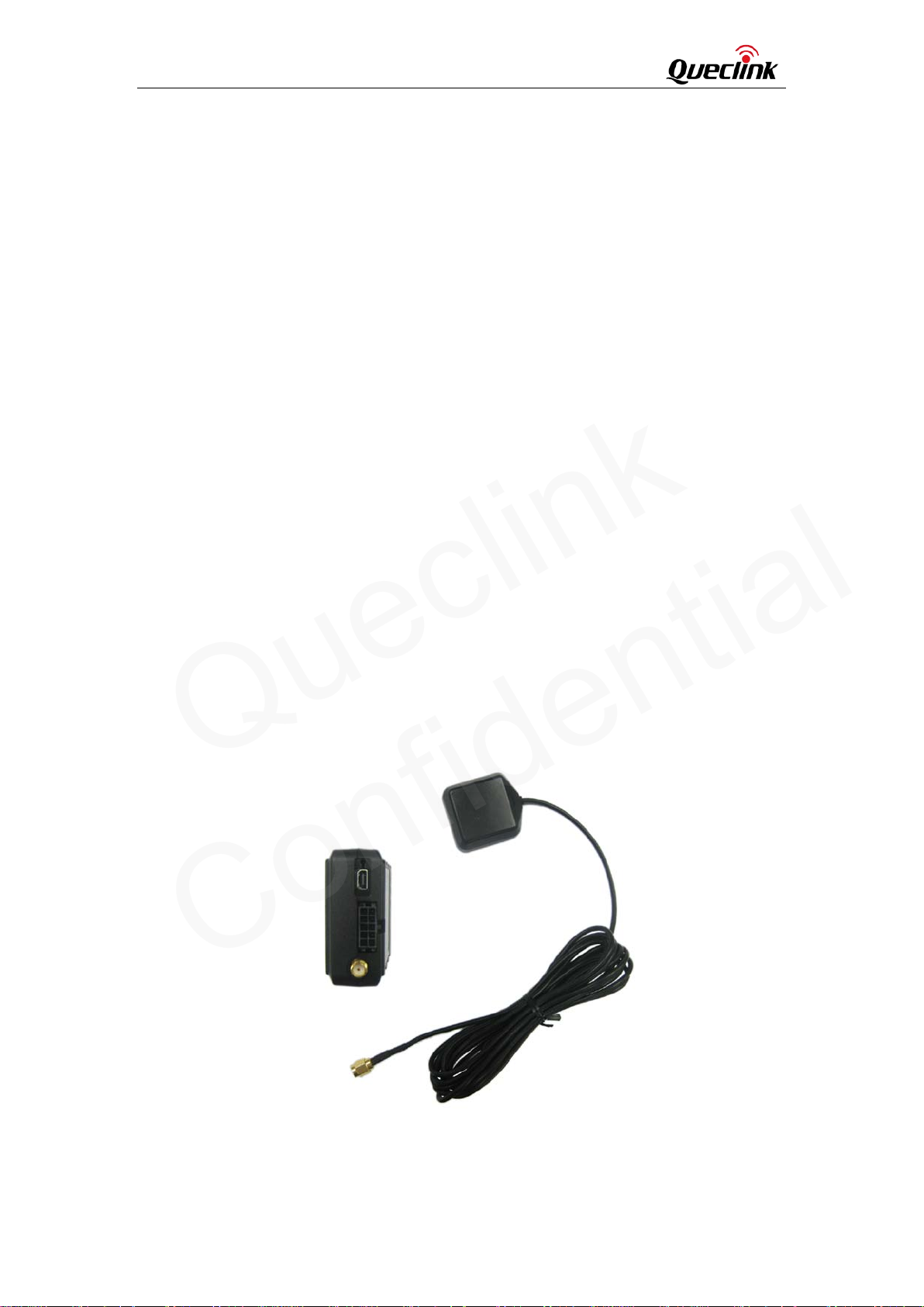
There is a SMA GPS antenna connector on GV65 Plus. The GV65 Plus will automatically detect
and use an external antenna when connected.
Figure 7. The External GPS Antenna of GV65 Plus
3.6.1. GPS Antenna Specification
TRACGV65PUM001 - 12 -
Page 14
GV65 Plus User Manual
onnection
Queclink
Confidential
Table 6. GPS Antenna Specification
GPS antenna Specification
Frequency
Bandwidth >5 MHz
Beam width >120 deg
Supply voltage 2.7V-3.3V
Polarization RHCP
Gain Passive: 0 dBi min
Impedance 50Ω
VSWR <2
Noise figure <3
3.7. Power C
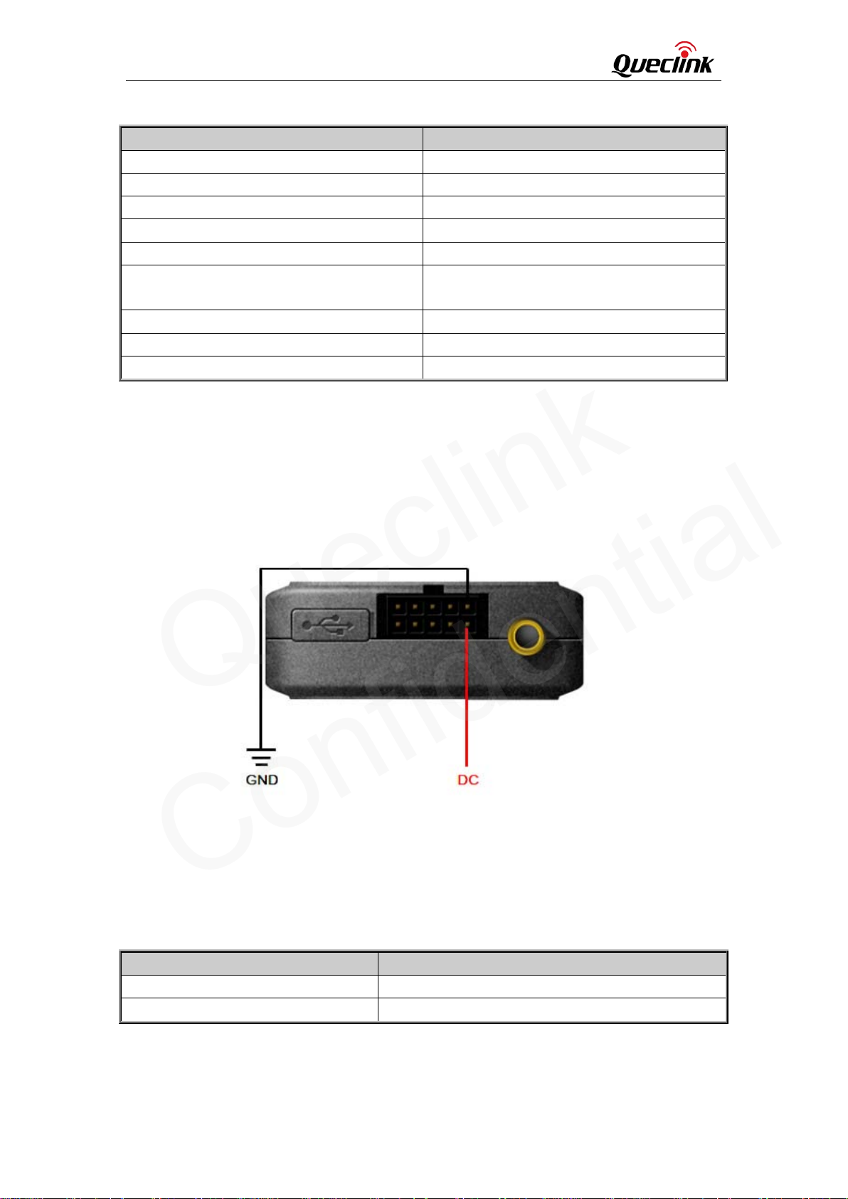
VIN (PIN1)/GND (PIN2) are the power input pins. The input voltage range for this device is from
8V to 32V. The device is designed to be installed in vehicles that operate on 12V or 24V systems
without the need for external transformers.
1575.42MHz
Active: 15 dB
Figure 8. Typical Power Connection
3.8. Ignition Detection
Table 7. Electrical Characteristics of Ignition Detection
Logical status Electrical status
Active 5.0V to 32V
Inactive 0V to 3V or open
TRACGV65PUM001 - 13 -
Page 15
GV65 Plus User Manual
Digital Inputs
Queclink
Confidential
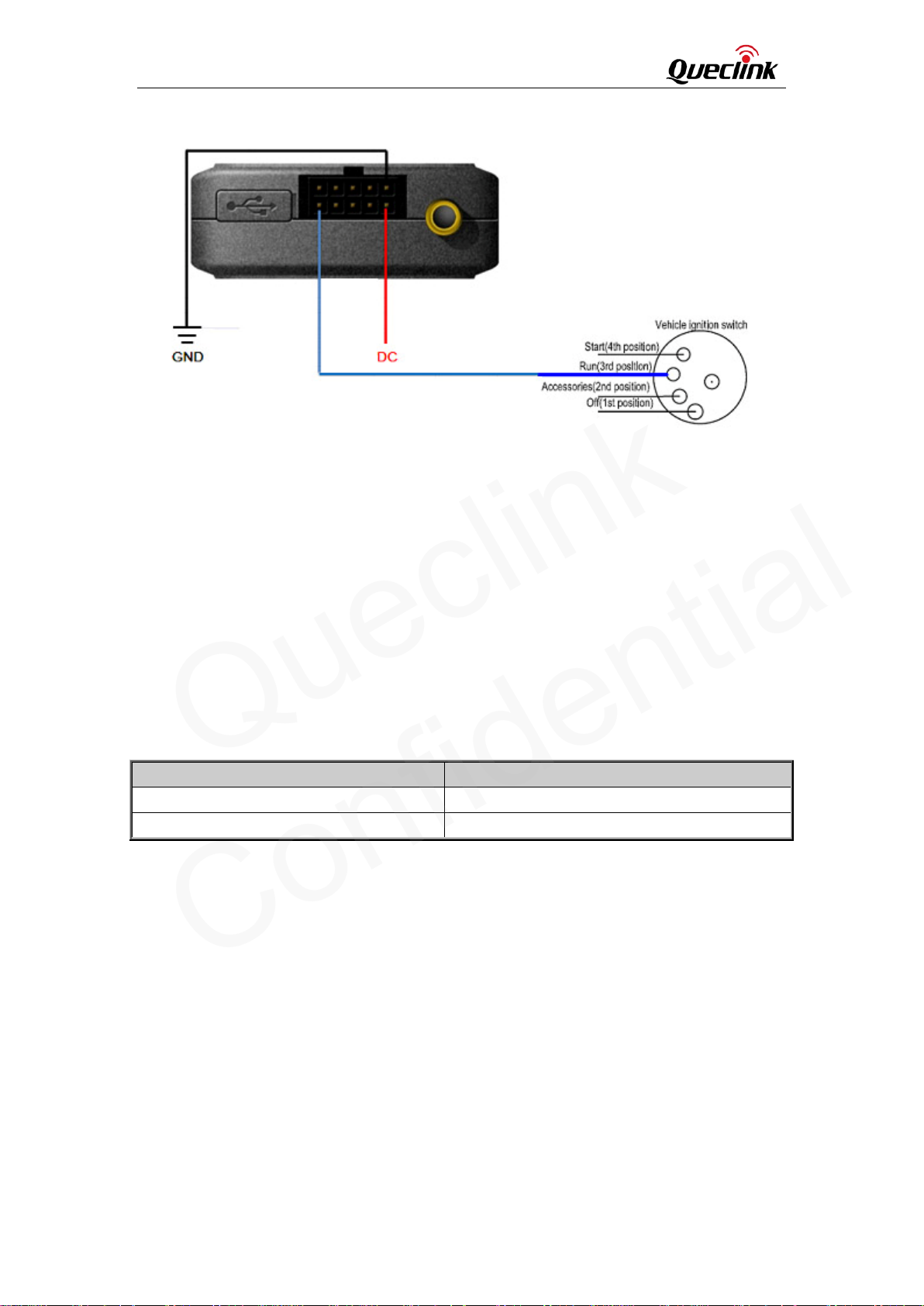
Figure 9. Typical Ignition Detection
IGN (Pin9) is used for ignition detection. It is strongly recommended to connect this pin to
ignition key “RUN” position as shown above.
An alternative to connecting to the ignition switch is to find a non-permanent power source that
is only available when the vehicle is running. For example, the power source for the FM radio.
IGN signal can be configured to start transmitting information to the backend server when
ignition is on and enter power saving mode when ignition is off.
3.9.
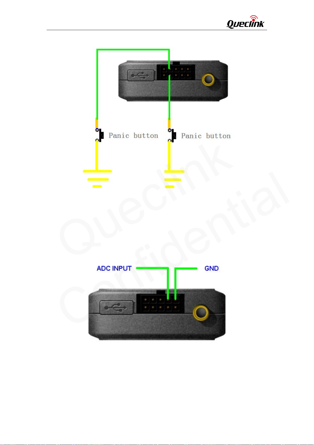
There are two general purpose digital inputs on GV65 Plus. They are all negative triggers.
Table 8. Electrical Characteristics of the Digital Inputs
Logical status Electrical characteristics
Active 0V to 0.8V
Inactive Open
The following diagram shows the recommended connection of the two digital inputs.
TRACGV65PUM001 - 14 -
Page 16
GV65 Plus User Manual
Queclink
Confidential
Figure 10. Typical Digital Input Connection
3.10. Analog Inputs
There is one analog input on GV65 Plus. The analog input voltage range could be selectable,
including 0-12V and 0-30V, and the default range is from 0 to 30V. The following diagram shows
the recommended connection.
Figure 11. Typical Digital Input Connection
3.11. Digital Outputs
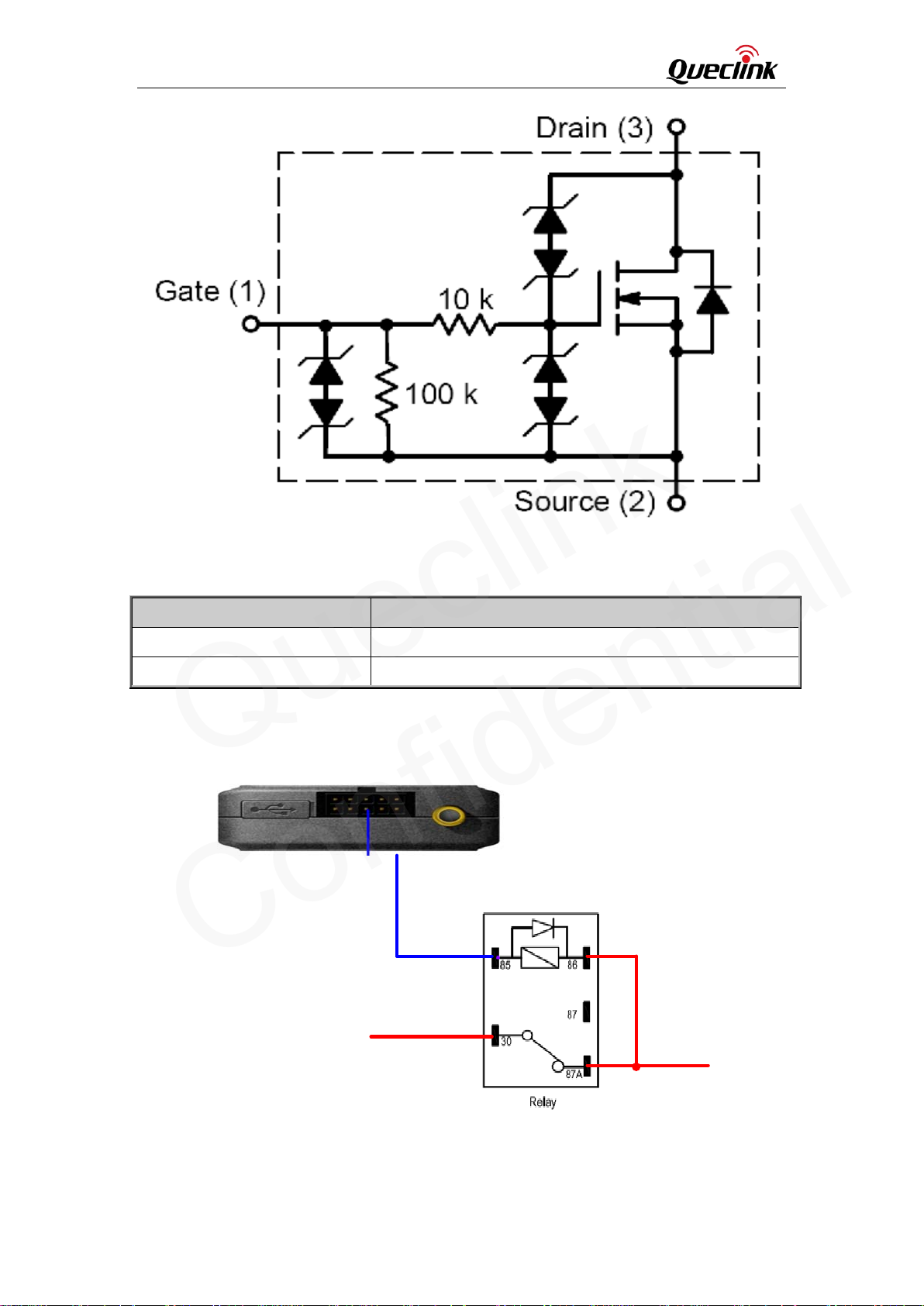
There are two digital outputs on GV65 Plus. All are of open drain type and the maximum drain
current is 150 mA. Each output has the built-in over current PTC resettable fuse.
TRACGV65PUM001 - 15 -
Page 17
GV65 Plus User Manual
Queclink
Confidential
Figure 12. Digital Output Internal Drive Circuit
Table 9. Electrical Characteristics of Digital Outputs
Logical status Electrical characteristics
Enable <1.5V @150 mA
Disable Open drain
Figure 13. Typical Connection with Relay
TRACGV65PUM001 - 16 -
Page 18
GV65 Plus User Manual
Device Status LED
Queclink
Confidential
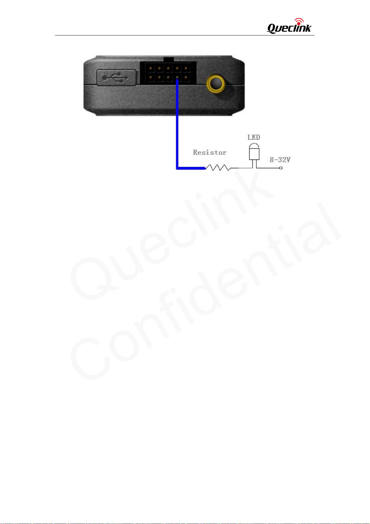
Figure 14. Typical Connection with LED
Note:
1 - OUT1 will latch the output state during reset.
2- Many modern relays come with a flyback diode pre-installed internal to the relay itself. If the
relay has this diode, ensure the relay polarity is properly connected. If this diode is not internal, it
should be added externally. A common diode such as a 1N4004 will work in most circumstances.
3.12.
TRACGV65PUM001 - 17 -
Page 19
GV65 Plus User Manual
Queclink
Confidential
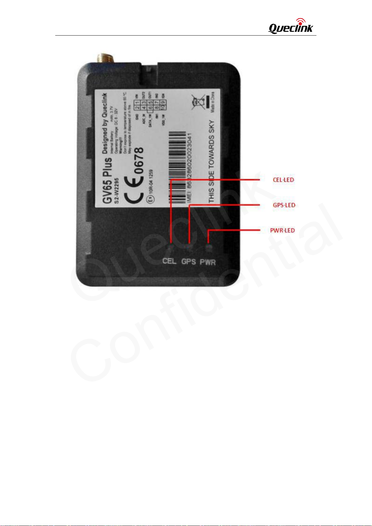
Figure 15. GV65 Plus LED on the Case
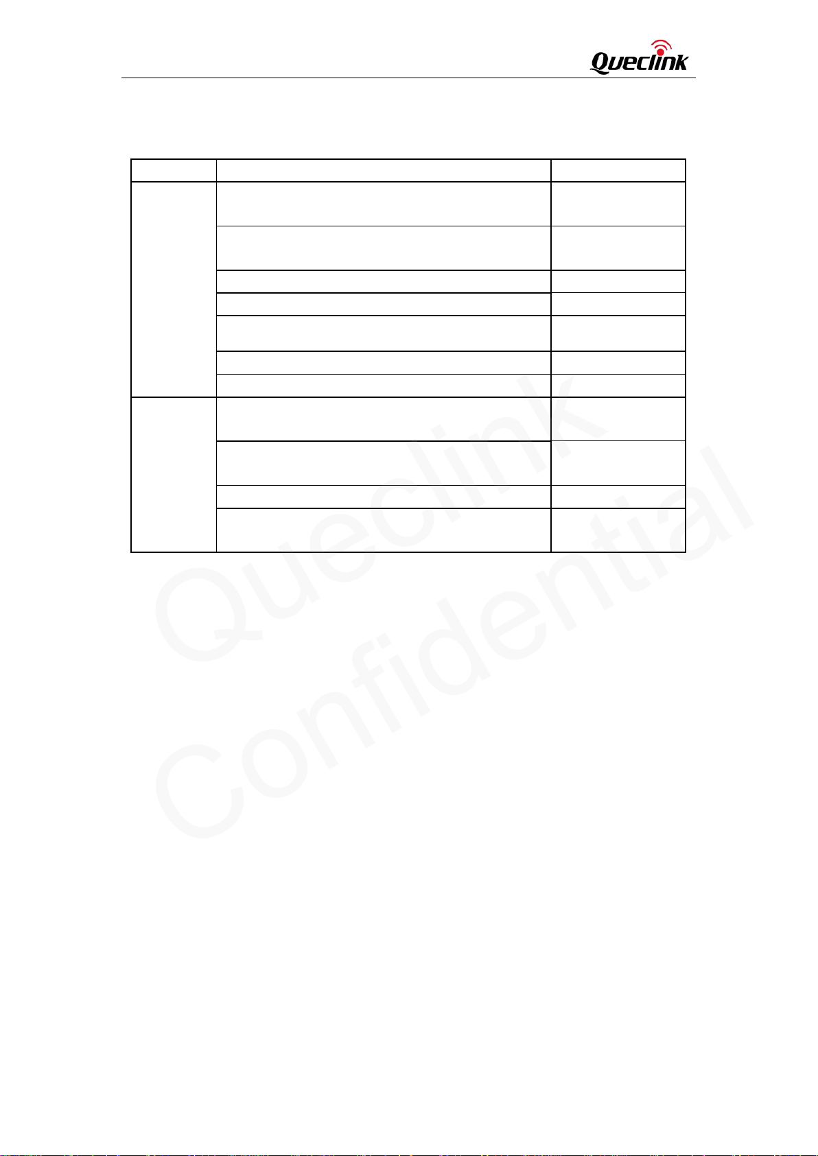
GV65 Plus has three status LEDs, namely, CEL, GPS and PWR.
TRACGV65PUM001 - 18 -
Page 20
GV65 Plus User Manual
External power in and internal battery is fully
wire Device Connection
Queclink
Confidential
Table 10. Definition of Device Status and LED
LED Device status LED status
GSM
(note1)
GPS
(note 2)
PWR
(note 2)
Note:
1 - GSM LED cannot be configured.
2 - GPS LED and PWR LED can be configured to turn off after a period of time by using the
configuration tool.
3 - Fast flashing is about 60 ms ON/780 ms OFF.
4 - Slow flashing is about 60 ms ON/1940 ms OFF.
Device is searching GSM network. Fast flashing
(Note 3)
Device has registered to GSM network. Slow flashing
(Note 4)
SIM card needs pin code to unlock. ON
GPS chip is powered off. OFF
GPS sends no data or data format error occurs. Slow flashing
GPS chip is searching GPS info. Fast flashing
GPS chip has gotten GPS info. ON
No external power and internal battery voltage is
lower than 3.35V.
No external power and internal battery voltage is
below 3.5V.
External power in and internal battery is charging. Fast flashing
charged.
OFF
Slow flashing
ON
3.13. 1-
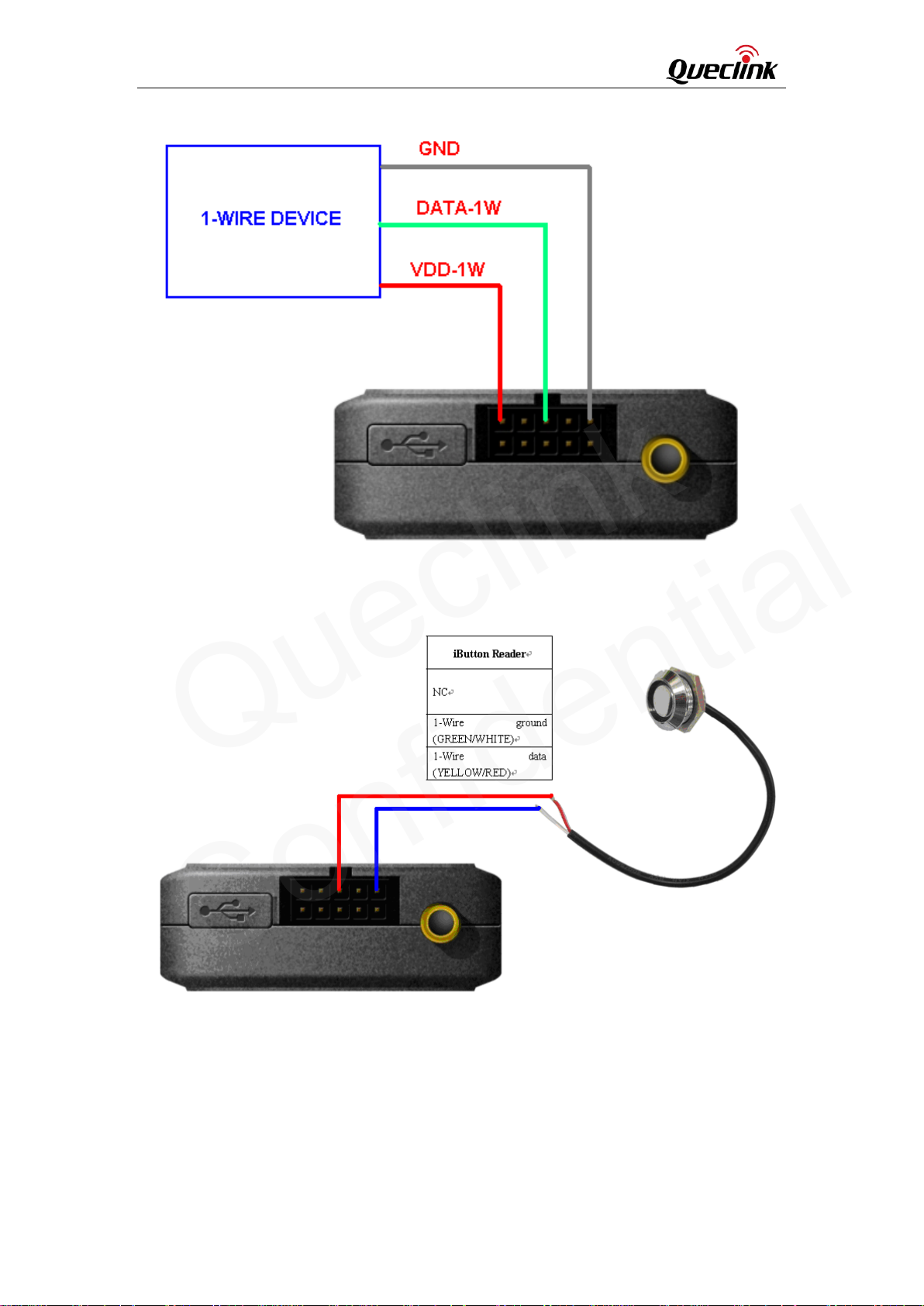
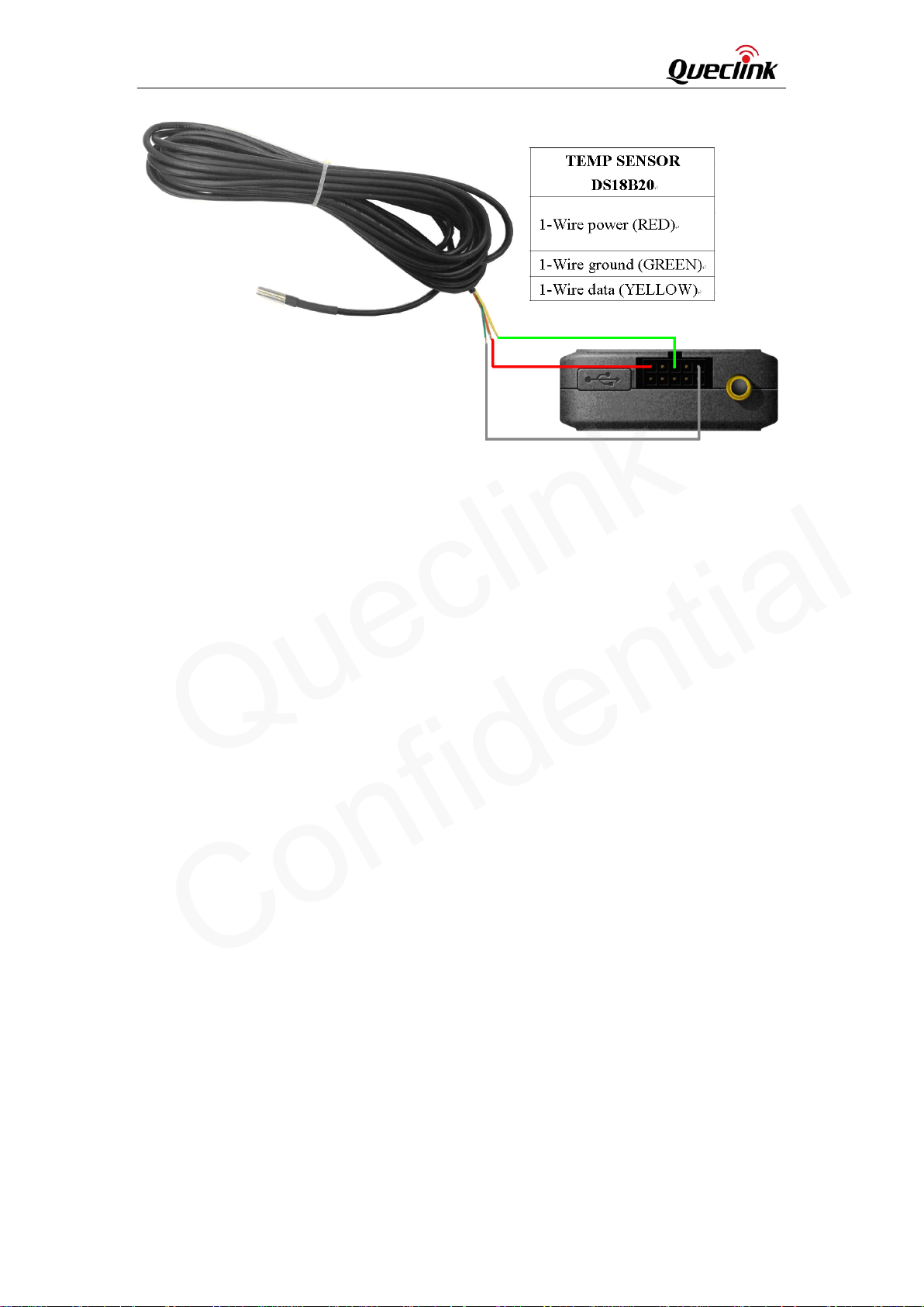
It has 1-wire bus on GV65 Plus, which supports temperature sensors and iButton. The bus
includes 3 signals, namely, VDD-1W, DATA-1W and GND. VDD-1W is the power output
for 1-wire device, and DATA-1W is the data signal, with which GV65 Plus can get
information from 1-wire device.
The following diagrams show the recommended connection of 1-wire device.
TRACGV65PUM001 - 19 -
Page 21
GV65 Plus User Manual
Queclink
Confidential
Figure 16. Typical Connection with 1-wire Device
Figure 17. Typical Connection with iButton Re a der
TRACGV65PUM001 - 20 -
Page 22
GV65 Plus User Manual
Queclink
Confidential
Figure 18. Typical Connection with Temperature Sensor
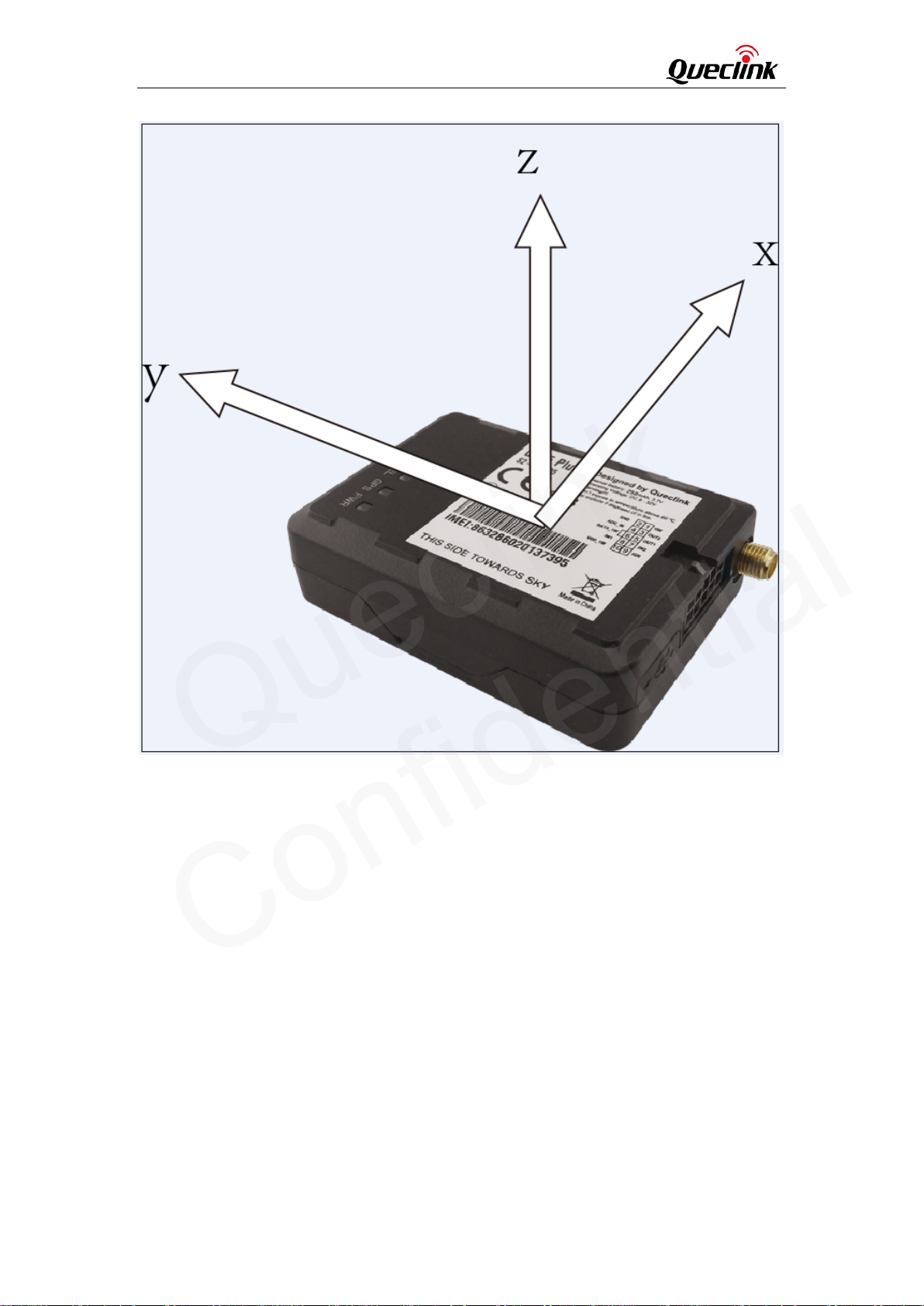
3.14. Motion Sensor Direction
GV65 Plus has an internal 3-axis accelerometer supporting driving behavior monitoring,
power conservation and motion detection.The following is the direction of the motion
sensor.
TRACGV65PUM001 - 21 -
Page 23
GV65 Plus User Manual
Queclink
Confidential
Figure 19. Motion sensor direction
TRACGV65PUM001 - 22 -
 Loading...