

Page 1
GV300 User manual
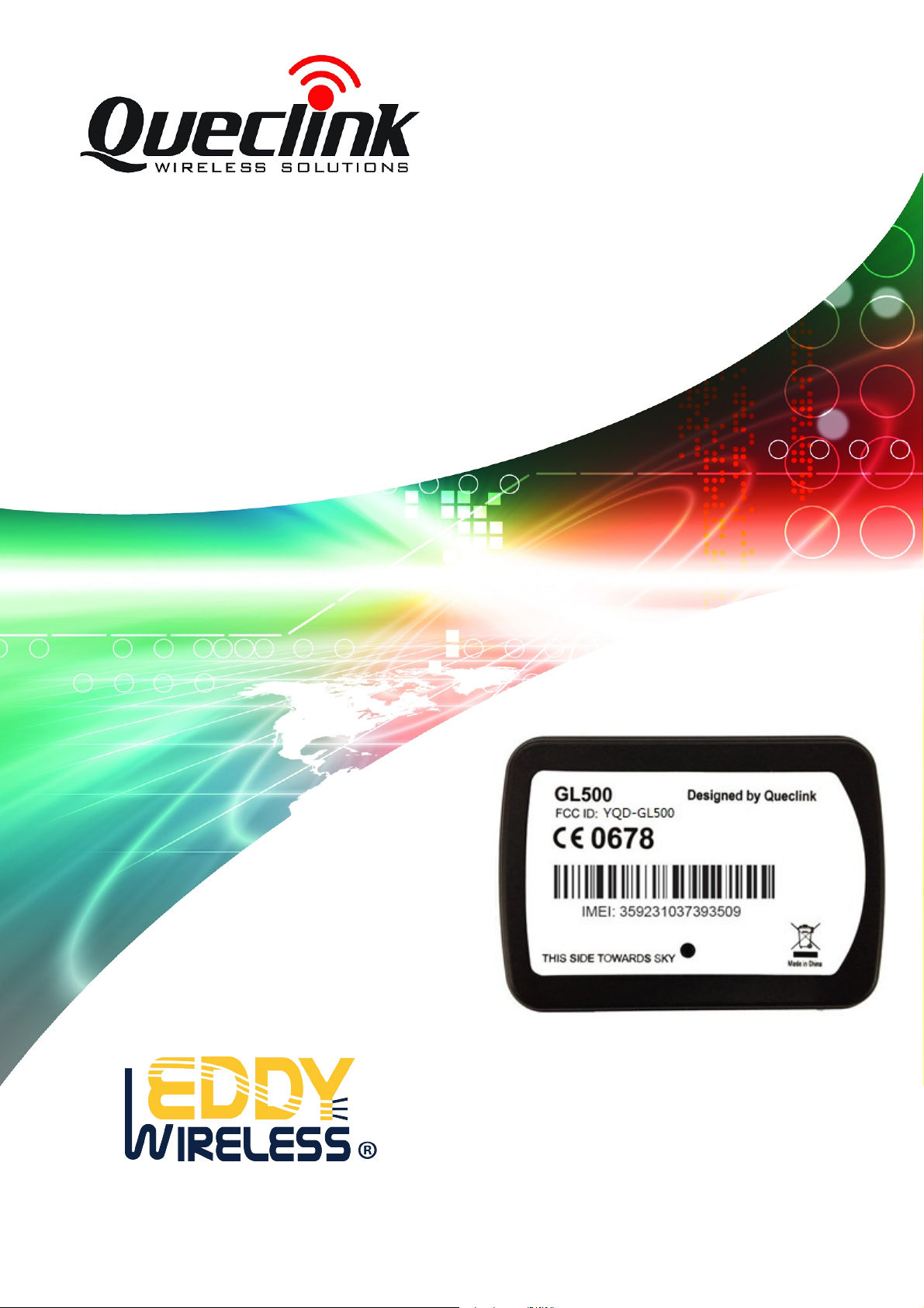
GSM/GPRS/GPS T racker GL500
User Manual
TRACGL500UM001
Revision
: 1.01
Page 2
GL500 User Manual
Document Title
Version
Date
Status
Document Control ID
GL500 User Manual
1.01
2013-6-5
Release
TRACGL500UM001
General Notes
Queclink offers this information as a service to its customers, to support application and
engineering efforts that use the products designed by Queclink. The information provided
is based upon requirements specifically provided to Queclink by the customers. Queclink
has not undertaken any independent search for additional relevant information, including
any information that may be in the customer’s possession. Furthermore, system validation
of this product designed by Queclink within a larger electronic system remains the
responsibility of the customer or the customer’s system integrator. All specifications
supplied herein are subject to change.
Copyright
This document contains proprietary technical information which is the property of Queclink
Limited., copying of this document and giving it to others and the using or communication
of the contents thereof, are forbidden without express authority. Offenders are liable to the
payment of damages. All rights reserved in the event of grant of a patent or the
registration of a utility model or design. All specification supplied herein are subject to
change without notice at any time.
Copyright © Shanghai Queclink Wireless Solutions Co., Ltd. 2011
TRACGL500UM001 - 2 -
Page 3

GL500 User Manual
Contents
Contents ............................................................................................................................................3
1. Introduction...................................................................................................................................
1.1. Reference.............................................................................................................................7
1.2. Terms and Abbreviations.....................................................................................................7
2. Product Overview .........................................................................................................................8
2.1. Check Parts List ..................................................................................................................8
2.2. Parts List..............................................................................................................................9
2.3. Interface Definition.............................................................................................................9
3. Getting Started............................................................................................................................11
3.1. Opening the Case ..............................................................................................................11
3.2. Closing the Case................................................................................................................11
3.3. Installing a SIM Card........................................................................................................11
3.4. Installing the Internal Backup Battery...............................................................................12
3.5. Power On the Device.........................................................................................................13
3.6. Direction of GL500 Placed ...............................................................................................13
3.7. Device Status LED............................................................................................................14
7
TRACGL500UM001 - 3 -
Page 4

GL500 User Manual
Table Index
Table 1. GL500 Protocol Reference........................................................................................7
Table 2. Terms and Abbreviations...........................................................................................7
Table 3. Parts List ...................................................................................................................9
Table 4. Description of 8 PIN Connections ..........................................................................10
Table 5. Definition of Device status and LED......................................................................14
TRACGL500UM001 - 4 -
Page 5

GL500 User Manual
Figure Index
Figure 1. Appearance of GL500.......................................................................................8
Figure 2. The 8 PIN connector on the GL500................................................................10
Figure 3. Opening the Case ............................................................................................11
Figure 4. Closing the Case..............................................................................................11
Figure 5. SIM Card Installation......................................................................................12
Figure 6. Backup Battery Installation.............................................................................12
Figure 7. GL500 Status LED..........................................................................................13
Figure 8. Direction of GL500 Placed .............................................................................13
TRACGL500UM001 - 5 -
Page 6
GL500 User Manual
Revision History
Revision Date Author Description of change
1.00 2012-6-11 Cid Xu Initial
1.01 2013-6-3 Tony.Pei Add the direction of GL500 placed
TRACGL500UM001 - 6 -
Page 7
GL500 User Manual
1. Introduction
GL500 is a powerful GPS tracker designed for fixed asset tracking applications.GL500
work with two CR123A lithium-batterys.GL500 wakes up every 1-40hours and sends the
info and then return to deepsleep.GL500 can standby 1000days. With built-in motion
sensor, GL500 can also detect the motion of asset all the time and give a warning
message. Based integrated @track protocol, the GL500 can communicate with a backend
server through the GPRS/GSM network to transfer reports of emergency, geo-fence
boundary crossings, low battery or scheduled GPS position along with many other useful
functions. System Integrators can easily setup their tracking systems based on the
full-featured @Track protocol.
This device complies with Part 15 of the FCC Rules. Operation is subject to the following
two conditions:
(1) This device may not cause harmful interference.
(2) This device must accept any interference received, including interference that may
cause undesired operation.
1.1. Reference
Table 1. GL500 Protocol Reference
SN Document name Remark
[1] GL500 @SMS & @Track Interface Protocol The @SMS & @Track protocol
interface between GL500 and
backend server.
1.2. Terms and Abbr eviations
Table 2. Terms and Abbreviations
Abbreviation Description
AGND Analog Ground
AIN Analog Input
DIN Digital Input
DOUT Digital Output
GND Ground
MIC Microphone
RXD Receive Data
TXD Transmit Data
SPKN Speaker Negative
SPKP Speaker Positive
TRACGL500UM001 - 7 -
Page 8
GL500 User Manual
2. Product Overview
2.1. Check Parts List
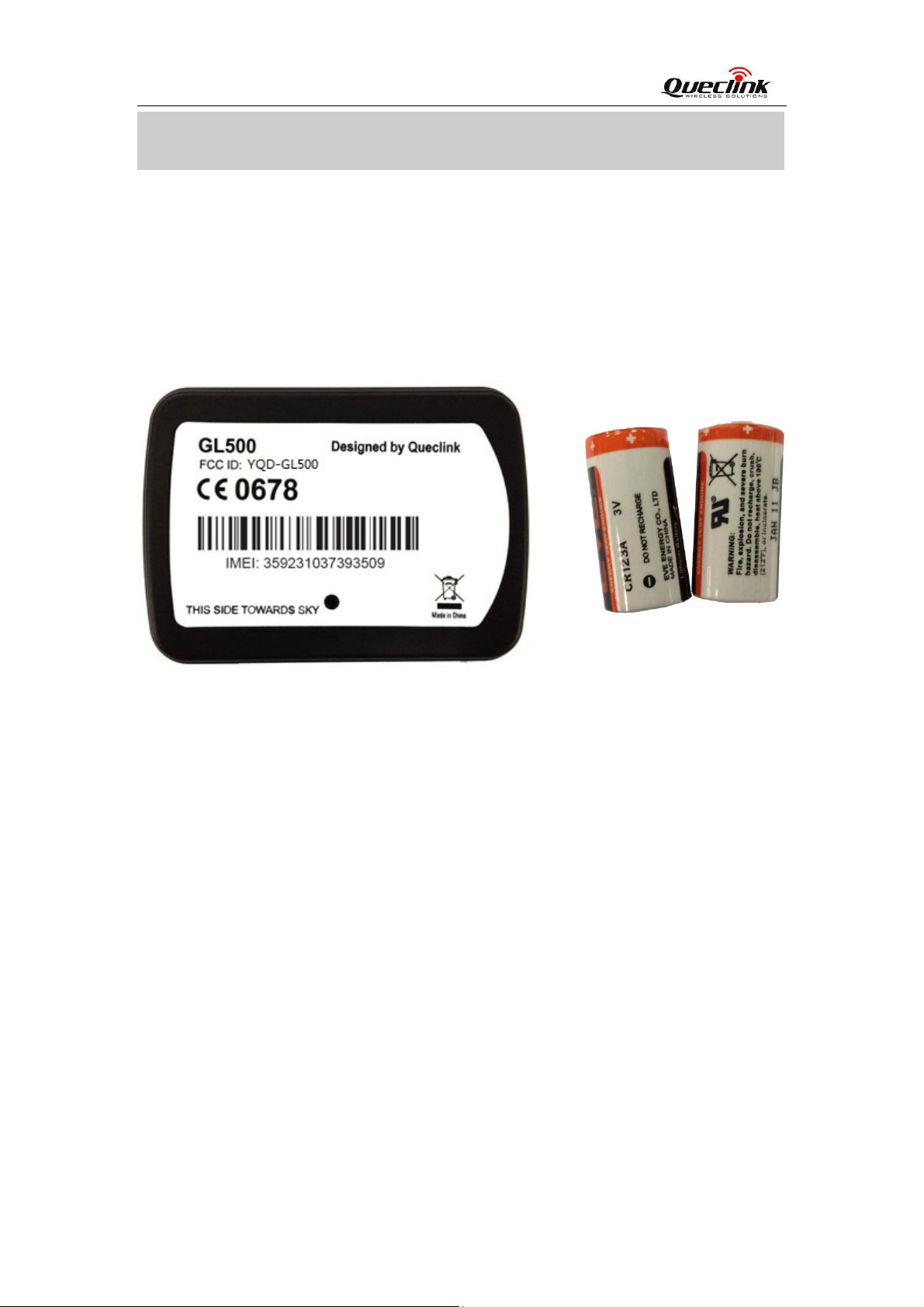
Before starting, check all the following items have been included with your GL500. If
anything is missing, please contact your supplier.
Figure 1. Appearance of GL500
TRACGL500UM001 - 8 -
Page 9
GL500 User Manual
2.2. Parts List
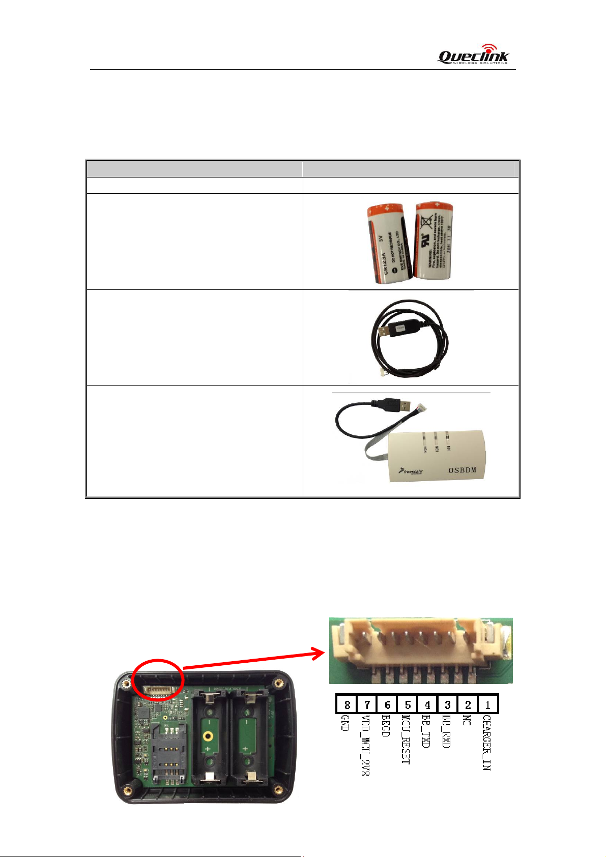
Table 3. Parts List
Name Picture
GL500 Locator 80*58*26.8 mm
CR123A Battery
GL500 Data Cable (Optional)
GL500 MCU Download Kit (Optional)
2.3. Interface Definition
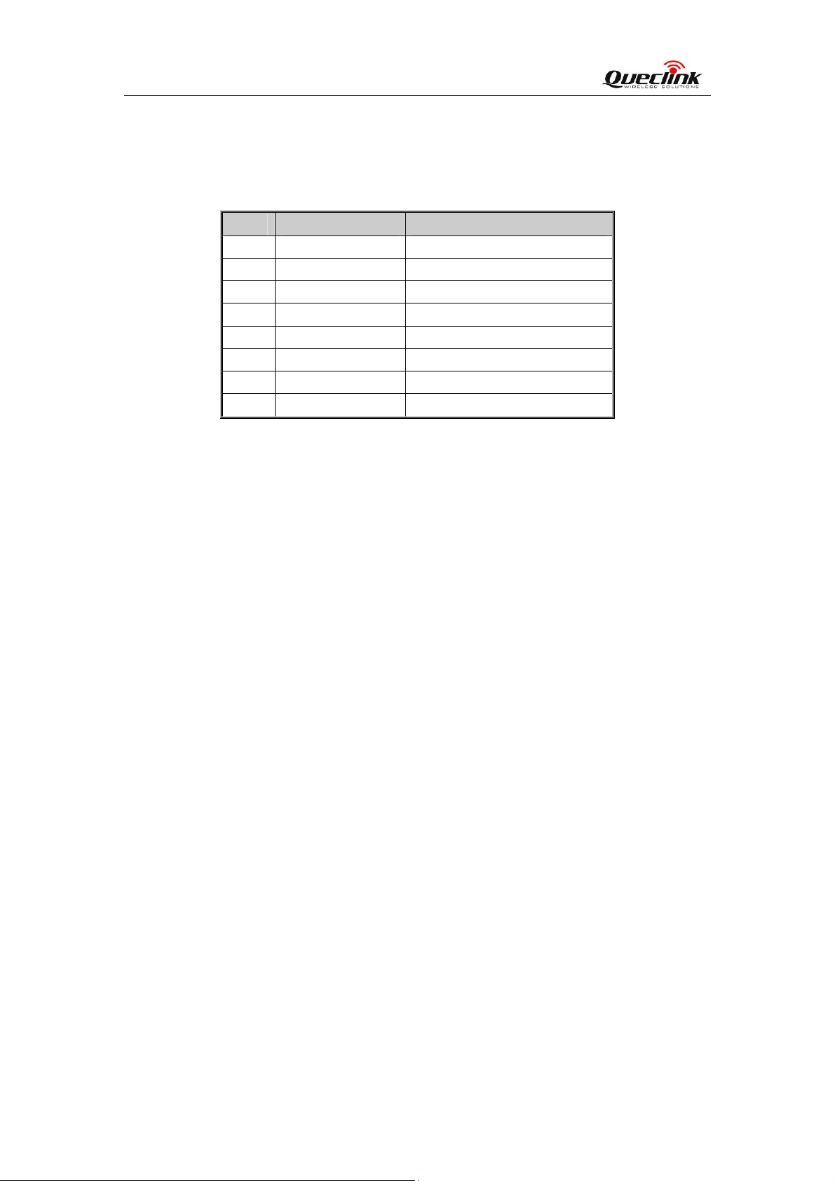
The GL500 has an 8 PIN interface connector. It contains the connections for power,
RS232, MCU Interface, etc. The sequence and definition of the 8PIN connector are shown
in following figure:
TRACGL500UM001 - 9 -
Page 10
GL500 User Manual
Figure 2. The 8 PIN connector on the GL500
Table 4. Description of 8 PIN Connections
Index Description Comment
1 CHARGER_IN External DC power input, 5V
2 NC Not connected
3 BB_RXD BB UART RXD
4 BB_TXD BB UART TXD
5 MCU_RESET MCU CHIP RESET SIGNAL
6 BKGD MCU CHIP BKGD SIGNAL
7 VDD_MCU_2V8
MCU POWER INPUT,2.8V
8 GND Power and digital ground
TRACGL500UM001 - 10 -
Page 11
GL500 User Manual
3. Getting Started
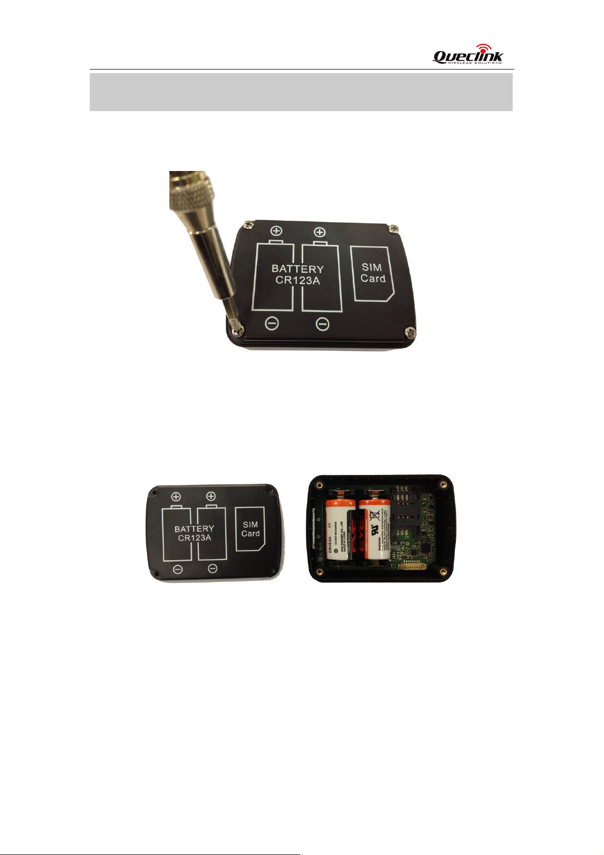
3.1. Opening the Case
Figure 3.
Use the Screwdriver to remove the screws, and then open the case.
Opening the Case
3.2. Closing the Case
Figure 4. Closing the Case
Place the cover in the correct position as shown in upon figure. Please note the battery
direction and SIM Card direction, and then tighten the screws with a Screwdriver.
3.3. Installing a SIM Card
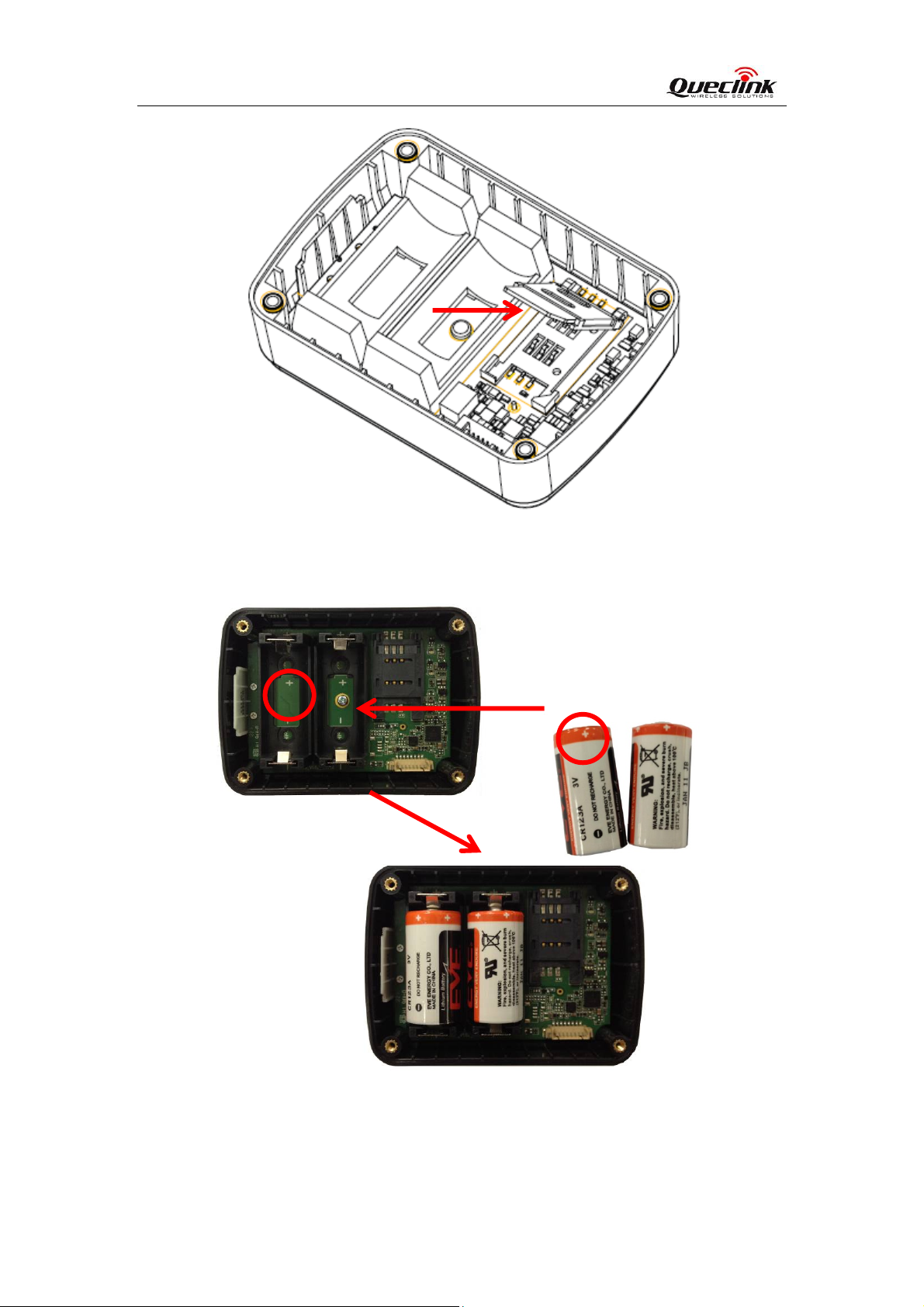
Open the case and ensure the unit is not powered (unplug the internal battery). Slide the
holder right to open the SIM card. Insert the SIM card into the holder as shown below with
the gold-colour contact area facing down taking care to align the cut mark. Close the SIM
card holder. Close the case.
TRACGL500UM001 - 11 -
Page 12
GL500 User Manual
Figure 5.
SIM Card Installation
3.4. Installing the Internal Backup Battery
Figure 6.
There have 2pcs internal CR123A battery for GL500, Insert the battery into the holder as
shown in upon figure, please note that the polarity mark of the battery and battery holder
need to be consistent.
Backup Battery Installation
TRACGL500UM001 - 12 -
Page 13
GL500 User Manual
3.5. Power On the Device
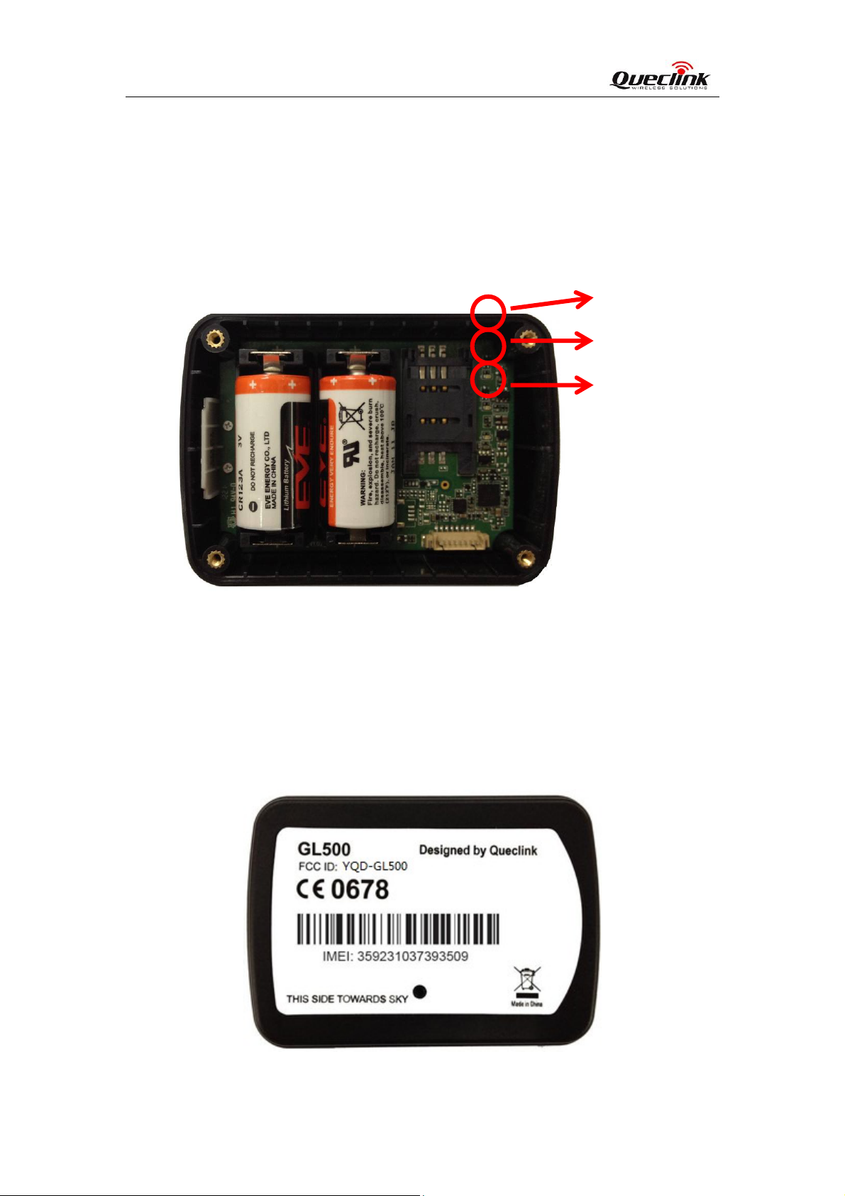
After inserted the Battery, GL500 will power on automatically, the Status LED will start
work, detail description in the next section.
Figure 7.
GL500 Status LED
Blue GPS
Red PWR
Green GSM
3.6. Direction of GL500 Placed
The side with label should towards sky to ensure there is good GPS signal can be
recieved.
Figure 8. Direction of GL500 Placed
TRACGL500UM001 - 13 -
Page 14
GL500 User Manual
3.7. Device Status LED
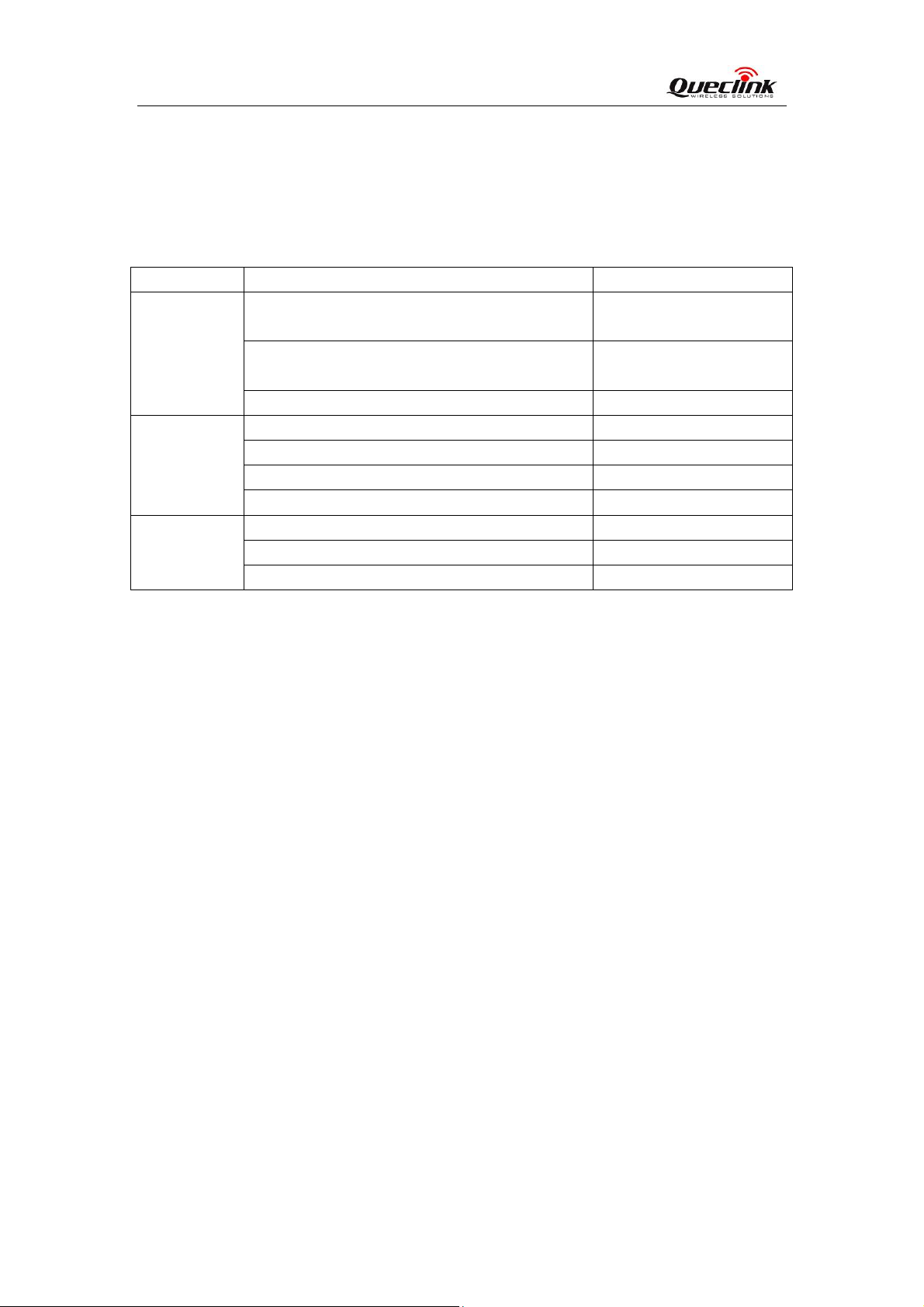
Table 5. Definition of Device status and LED
LED Device status LED status
GSM
(Green)
GPS
(Blue)
PWR
(Red)
1 - Fast flashing is about 60ms ON/ 780ms OFF
2 - Slow flashing is about 60ms ON/ 1940ms OFF
Note:
1, In Battery mode, all LEDs are only enabled at the first 5 minutes after power on the
device, and then will be shut down all the time.
Device is searching GSM network. Fast flashing
(Note1)
Device has registered to GSM network. Slow flashing
(Note2)
SIM card needs pin code to unlock. ON
GPS chip is powered off. OFF
GPS sends no data or data format error. Slow flashing
GPS chip is searching GPS info. Fast flashing
GPS chip has gotten GPS info. ON
Battery voltage is lower than 0%. OFF
Battery voltage is below 10%. Slow flashing
Battery voltage is more than 10%. ON
TRACGL500UM001 - 14 -
 Loading...