

Page 1
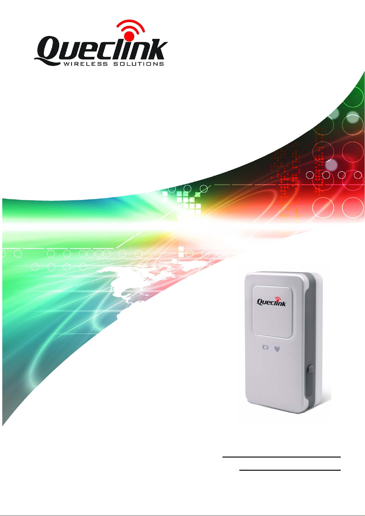
GSM/GPRS/GPS T racker GL100
User Guide
TRACGL100UM002
Revision: 2.03
http://www.queclink.com
Page 2
GL100 User manual
Queclink
Confidential
Document Title
Version
Date
Status
Document Control ID
General Notes
Queclink offers this information as a service to its customers, to support application and
engineering efforts that use the products designed by Queclink. The information provided is
based upon requirements specifically provided to Queclink by the customers. Queclink has
not undertaken any independent search for additional relevant information, including any
information that may be in the customer’s possession. Furthermore, system validation of this
product designed by Queclink within a larger electronic system remains the responsibility of
the customer or the customer’s system integrator. All specifications supplied herein are
subject to change.
Copyright
This document contains proprietary technical information which is the property of Queclink
Limited., copying of this document and giving it to others and the using or communication of
the contents thereof, are forbidden without express authority. Offenders are liable to the
payment of damages. All rights reserved in the event of grant of a patent or the registration of
a utility model or design. All specification supplied herein are subject to change without
notice at any time.
Copyright © Queclink Wireless Solutions Ltd. 2010
GL100 User manual
2.03
2010-11-24
Release
TRACGL100UM002
TRACGL100UM002 - 1 -
Page 3
GL100 User manual
Queclink
Confidential
Contents
Contents ............................................................................................................................................2
0. Revision history ............................................................................................................................3
1. Introduction...................................................................................................................................4
2. Product Overview .........................................................................................................................5
2.1. Appearance..........................................................................................................................5
2.2. Buttons/Mini USB Interface Description............................................................................5
2.3. T wo Triple-Color LEDs Description...................................................................................6
3. Getting Started ..............................................................................................................................8
3.1. Parts List..............................................................................................................................8
3.2. Battery Charging.................................................................................................................9
3.3. Install SIM Card................................................................................................................10
3.4. Turn on/T urn off................................................................................................................10
3.5. Operating on function key.................................................................................................10
4. GL100 Manager Setup Wizard ...................................................................................................11
4.1. Main setting.......................................................................................................................11
4.2. The main window..............................................................................................................12
4.3. Protocol Commands History.............................................................................................13
4.4. An example to configure GL100.......................................................................................14
4.4.1. Set the parameters of main backend server.....................................................14
4.4.2. Set the parameters of secondary backend server.............................................15
4.4.3. Set the parameters of scheduled fixed timing report.......................................16
4.4.4. Set the parameters of Geo-Fence.....................................................................17
4.4.5. Set the parameters of special function.............................................................18
4.4.6. Set the parameters of Synchronization ACK setting.......................................19
4.4.7. Real Time Operation.......................................................................................20
4.4.8. Set the parameters of google link function......................................................24
4.4.9. Set the parameters of white call list.................................................................25
5. Troubleshooting and Safety info.................................................................................................26
5.1. Troubleshooting.................................................................................................................26
5.2. Safety info.........................................................................................................................27
TRACGL100UM002 - 2 -
Page 4
GL100 User manual
Queclink
Confidential
0. Revision history
Revision Date Author Description of change
2.01 2009-08-07 Moon XIE Initial
2.02 2009-12-09 Ella HUANG Update parameters of special function in chapter
4.4.5
2.03 2010-11-03 Ella HUANG 1. Add Chapter 4.4.8 and 4.4.9;
2. Update parameters of real time operation in
chapter 4.4.7.
TRACGL100UM002 - 3 -
Page 5
GL100 User manual
Queclink
Confidential
1. Introduction
GL100 is a powerful GPS locator which is designed for vehicle, pets and asserts tracking. With
superior receiving sensitivity, fast TTFF and GSM frequencies 850/900/1800/1900. Its location
can be real time or schedule tracked by backend server or specified terminals. Based on the
embedded @Track protocol, GL100 can communicate with the backend server through
GPRS/GSM network, and transfer reports of emergency, Geo-fencing, device status and scheduled
GPS position etc… Service provider is easy to setup their tracking platform based on the
functional @Track protocol.
TRACGL100UM002 - 4 -
Page 6
GL100 User manual
Queclink
Confidential
2. Product Overview
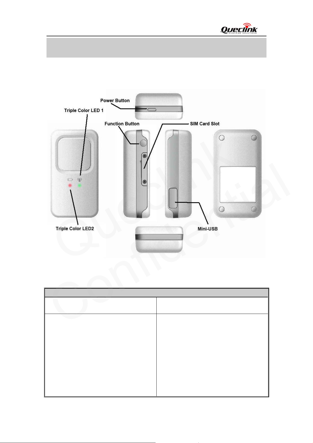
2.1. Appearance
2.2. Buttons/Mini USB Interface Description
Button /Mini USB Interface Description
Power Key z Turn on GL100
z Turn off GL100 (If power key is enabled).
Function Key z Geo-Fence mode (default)
Press the key twice in 2 seconds to
enable/disable Geo-Fence0
z SOS mode
Keep pressing the key for 3 seconds to
enter the SOS mode
z Location Geo-Fence mode
Press the key twice in 2 seconds to enable
or disable Geo-Fence mode and use the
current position as the centre of Geo-Fence
TRACGL100UM002 - 5 -
Page 7
GL100 User manual
Queclink
Confidential
0.
z Emergent SOS mode
Keep pressing the key for 3 seconds, and
GL100 report the current position
according to the result of the latest GPS
fixing and then start GPS fixing. After the
GPS fixing finishes or timeout, the device
will report the SOS message according the
result of the GPS fixing.
Note: Function key shall be enabled.
Mini USB interface z Plug in the AC-DC power adapter to this
interface for charging battery.
z Backend server developer or administrator
can use the Data_Cable to configure
GL100.
2.3. Two Triple-Color LEDs Description
There are two triple-color LEDs in GL100. Each LED shows red, green and blue to indicate
different state of GL100. For better understanding, we call them Red LED 1, Green LED 1, Blue
LED 1 and Red LED 2, Green LED 2, Blue LED 2.
Light Color event State
LED1
Green
Blue
LED2
Blue
The power key has been pressed light Red
The device receives a valid
command
network searching fast flash
network has been registered slow flash
SIM pin locked ever-light
GPS is in fixing fast flash
GPS has fixed ever-light for 2 seconds
power is low ever-light Red
The device is in charging slow flash
charging has completed ever-light Green
After inserting the charger light for 8 seconds to indicate the
Case 1: Geo-Fence mode/
light
battery status is checked
Location Geo-Fence mode
Blue led2 will be solid if the
function key is pressed. After that
if the user press the function key
one more time in 2 seconds the
blue LED2 will be off and he new
Geo-Fence center will be set after
successful GPS fix.
Case 2: SOS mode/Emergent
TRACGL100UM002 - 6 -
Page 8
GL100 User manual
Queclink
Confidential
SOS mod
The blue led2 will be solid when
the function key is pressed. It will
be off after the function key
released. User should press the
function key for at least 3 seconds
to start SOS report.
TRACGL100UM002 - 7 -
Page 9
GL100 User manual
Queclink
Confidential
3. Getting Started
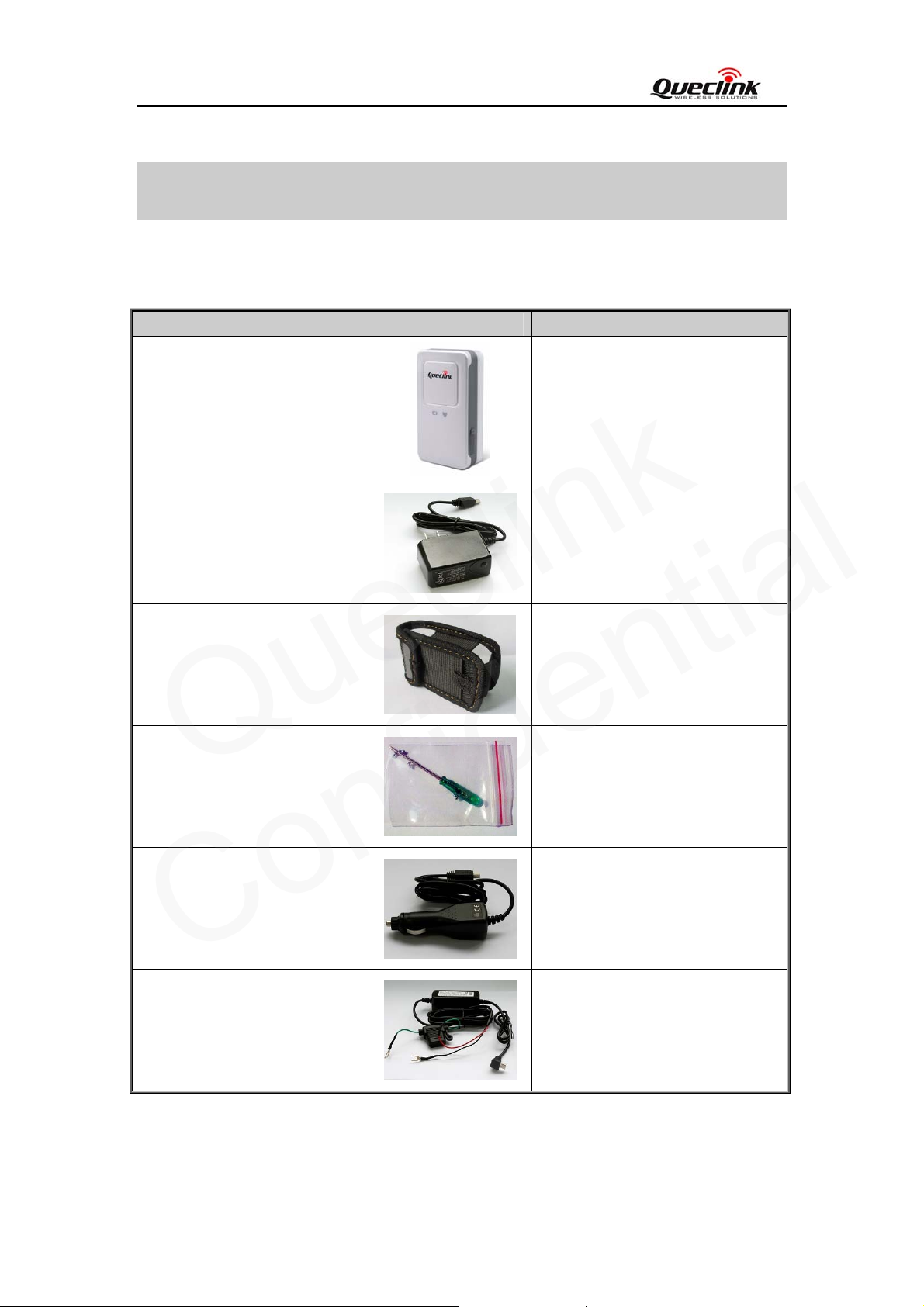
3.1. Parts List
Name Picture Remark
GL100 Locater
AC-DC Power Adapter
(Standard accessory)
The GSM/GPRS/GPS locator.
It is used to charge the internal
battery of GL100.
GL100 Sheath
(Standard accessory)
Screw Driver
(Standard accessory)
Car Cigarette Charger
(Optional accessory)
Car Kit Charger
(Optional accessory)
It is used to attach the GL100 to
belt.
It is used to twist off/ tighten the
two screws on the side of GL100
when install SIM card.
It is used to power the GL100 with
the cigarette power output on the
vehicle.
It is used to power the GL100 with
the battery output on the vehicle.
TRACGL100UM002 - 8 -
Page 10
GL100 User manual
Queclink
Confidential
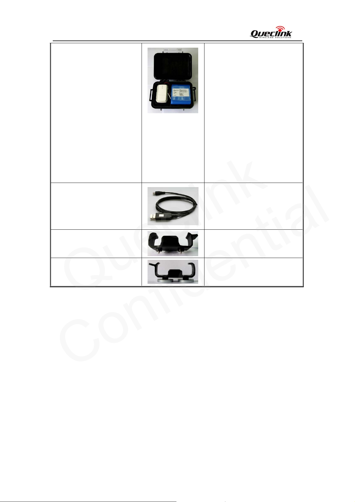
External Battery Kit
(Optional accessory)
GL100 Data Cable
(Optional accessory)
It is a set of accessories include an
external battery, a power control
unit and a pelican waterproof
casing. It will greatly improve the
working time of GL100 and also let
the GL100 can be used for some
special application like container
tracking.
Please refer to “GL100 External
Battery Kit User Manual.pdf” for
detail.
Please notice the external battery kit
only works on a special hardware
version of GL100 which called
GL100NB.
It the USB data cable which can be
used for firmware upgrading and
configuration.
GL100 Holder Without Magnet
(Optional accessory)
GL100 Holder With Magnet
(Optional accessory)
3.2. Battery Charging
z Please connect AC-DC power adapter with GL100.
z Insert the AC-DC power adapter into the power socket.
z During charging, the Red LED 2 is blinking slowly. When the battery is full charged, the
Green LED 2 will be solid.
z You can also charge the battery by USB cable which connects GL100 with the PC.
z Charging time is about 5 hours.
Note: Before the first time using GL100, please full charge the battery.
It is used to hold the GL100, mount
to somewhere with the screw.
It is used to hold the GL100,
attached to metal with the magnet
on it.
TRACGL100UM002 - 9 -
Page 11
GL100 User manual
Queclink
Confidential
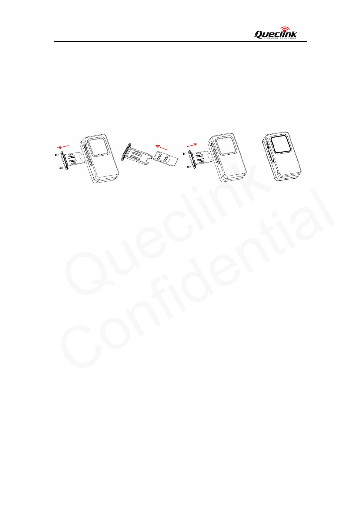
3.3. Install SIM Card
z Use a screw driver to twist off the two screws on the side of GL100.
z Then remove the screws and SIM cover.
z Insert the SIM card into the SIM cover according to the direction shown.
z Finally, put the SIM cover into the SIM slot and tighten screws.
3.4. Turn on/Turn off
z Turn on: Press the Power key at least 3 seconds and release it to turn on GL100. At the same
time, Red LED 1 will light on for 2~3 seconds. Then Green LED 1 starts to blink quickly
which means searching the GSM network. After the GSM network is registered, it turns to be
slow blinking.
z Turn off: Press the Power key at least 3 seconds; Red LED 1 will light on for 2~3 seconds
and then turn off, it indicates that GL100 is turned off. Please note the end-user can not power
off GL100 when the power key is disabled by protocol.
3.5. Operating on function key
z First please make sure the function key is enabled.
z When the function key is in Geo-Fence mode and the function key is enabled. To double press
the function key in 2 seconds will enable/disable the Geo-Fence 0.
Note: “Check interval”, “Central Point” and “Radius” of Geo-Fence0 shall be preset.
z When the function key is in SOS mode, Press the function key for 3 seconds, then GL100 will
report a +RESP:GTSOS message which includes the position information to the backend
server.
TRACGL100UM002 - 10 -
Page 12
GL100 User manual
Queclink
Confidential
4. GL100 Manager Setup Wizard
GL100 manager tool is PC software which can be used to configure GL100 through Data_Cable.
It is easy for the backend server developers to configure GL100 with manager tool, which has
friendly user interface. The correct command messages sent to GL100 will be displayed on the
manage tool.(These messages can also be sent by SMS or GPRS ).
The administrators can also use the manager tool to configure GL100 before selling. But it is
strongly recommended to establish a backend server and implement the way to control GL100 by
SMS or GPRS. Please refer to “GL100 @Track Air Interface Protocol” for detail.
Before using the manager tools please Find “PL2303_Prolific_DriverInstaller_v10518.zip” in
develop suit and install the drive for PL2303.After that a new COM port can be found in the PC
system, and then please follow the steps as below:
1. Power on GL100.
2. Connect GL100 to PC with Data_Cable.
3. Run “GL100 Manager Tool Vx.xx.exe”.
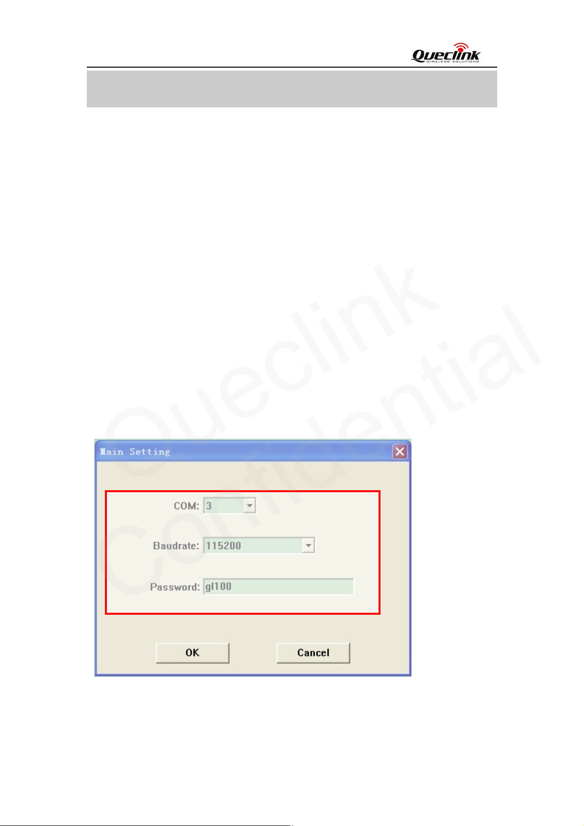
4.1. Main setting
Select the COM port and baud rate, input the password “gl100”, and the main window will
display.
TRACGL100UM002 - 11 -
Page 13
Menu
Queclink
Confidential
State
Display
Function
setting
GL100 User manual
4.2. The main window
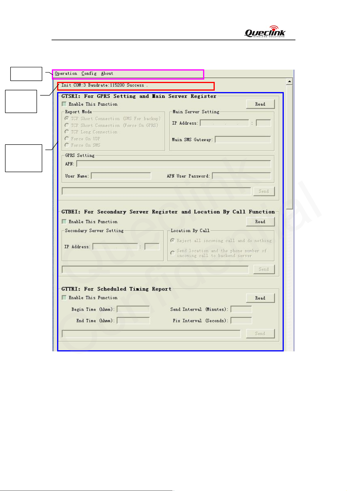
(1)Menu
[Operation]: Include two sub-menu items “Send All” and “Read All”.
“Send All” is used to send the configuration message which is enabled in zone
“Function setting”
“Read All” is used to read all the parameters from GL100 and display in zone
[Config]: Include “Main Setting”, “Save Config File” and “Load Config File”.
TRACGL100UM002 - 12 -
“Function setting”
Page 14
GL100 User manual
Queclink
Confidential
“Main setting” is used to configure the COM port and password. Please refer to chapter
4.1.
“Save Config File” is used to save all parameters to an ini file.
“Load Config File” is used to load all parameters from an ini file which was created
through menu item “Save Config File”
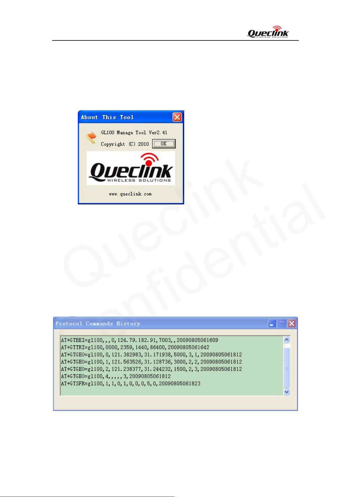
[About]: Select “About This Tool”. Then the following pop up window will display.
State Display
(2)
Display the state of operation, including the serial port state, baud rate state, and the operation
result.
(3)
Function setting
Set and view the parameters of the functions.
4.3. Protocol Commands History
The Protocol Commands History Dialog shows all the commands which have been sent to GL100
from the Manager Tool.
TRACGL100UM002 - 13 -
Page 15
GL100 User manual
Queclink
Confidential
4.4. An example to configure GL100
The manager tool is developed based on the @Track Air Interface Protocol. Please re fer to “GL100
@Track Air Interface Protocol” for detail.
Following is a general procedure to configure GL100 with manager tool.
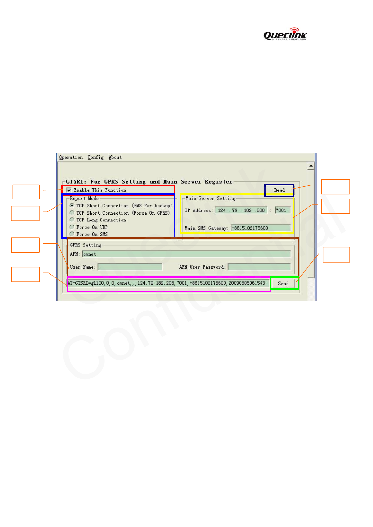
4.4.1. Set the parameters of main backend server
Step_1
Step_4
Step_5
Step_2
Step_1: Select “Enable This Function”, after that the parameters of GTSRI can be changed and
the "Send" button is enabled.
Step_2: When “Enable This Function” is selected, the command message which shall be sent to
GL100 will be generated based on input and displayed here. Please note this command
message can also be sent to GL100 through SMS or GPRS.
Step_3: It is recommended to read the parameters from GL100 and edit based on them.
Step_4: Set Report Mode. Please refer to “GL100 @Track Air Interface Protocol” for the meaning
of each choice.
Step_5: Set GPRS parameters. Please contact your SIM card provider to get the correct APN
information.
Step_6: Set the parameters of main backend server.
In the “IP Address” text box, input the internet IP address and port number of main
backend server. The valid value of port number is 0-65535.
Step_3
Step_6
Step_7
TRACGL100UM002 - 14 -
Page 16
Step_1
Queclink
Confidential
Step_4
GL100 User manual
In the “Main SMS Gateway” text box, input the phone number of main SMS gateway
which is used to receive the message from GL100 by SMS. The international format like
“+8615201772961” and short code like “10086” are both supported.
Step_7: Click the “Send” button; download the parameters of GTSRI to GL100.
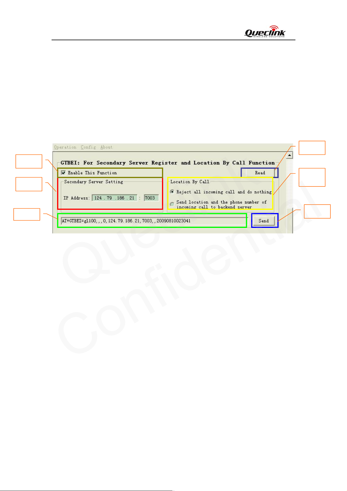
4.4.2. Set the parameters of secondary backend server
Step_3
Setp_5
Step2
Step_1: Select “Enable This Function”, after that the parameters of GTBE I can be changed and
the "Send" button is enabled.
Step_2: When “Enable This Function” is selected, the command message which shall be sent to
GL100 will be generated based on input and displayed here. Please note this command
message can also be sent to GL100 through SMS or GPRS.
Step_3: It is recommended to read the parameters from GL100 and edit based on them.
Step_4: Set the parameters of the secondary backend server.
In the “IP Address” text box, input the internet IP address and port number of the
secondary backend server. The valid value of port number is 0-65535.
Step_5: Location By Call. Configure the “Location By Call” function. Please refer to “GL100
@Track Air Interface Protocol” for detail.
Step_6: Click the “Send” button; download the parameters of GTBEI to GL100.
Step_6
TRACGL100UM002 - 15 -
Page 17
GL100 User manual
Queclink
Confidential
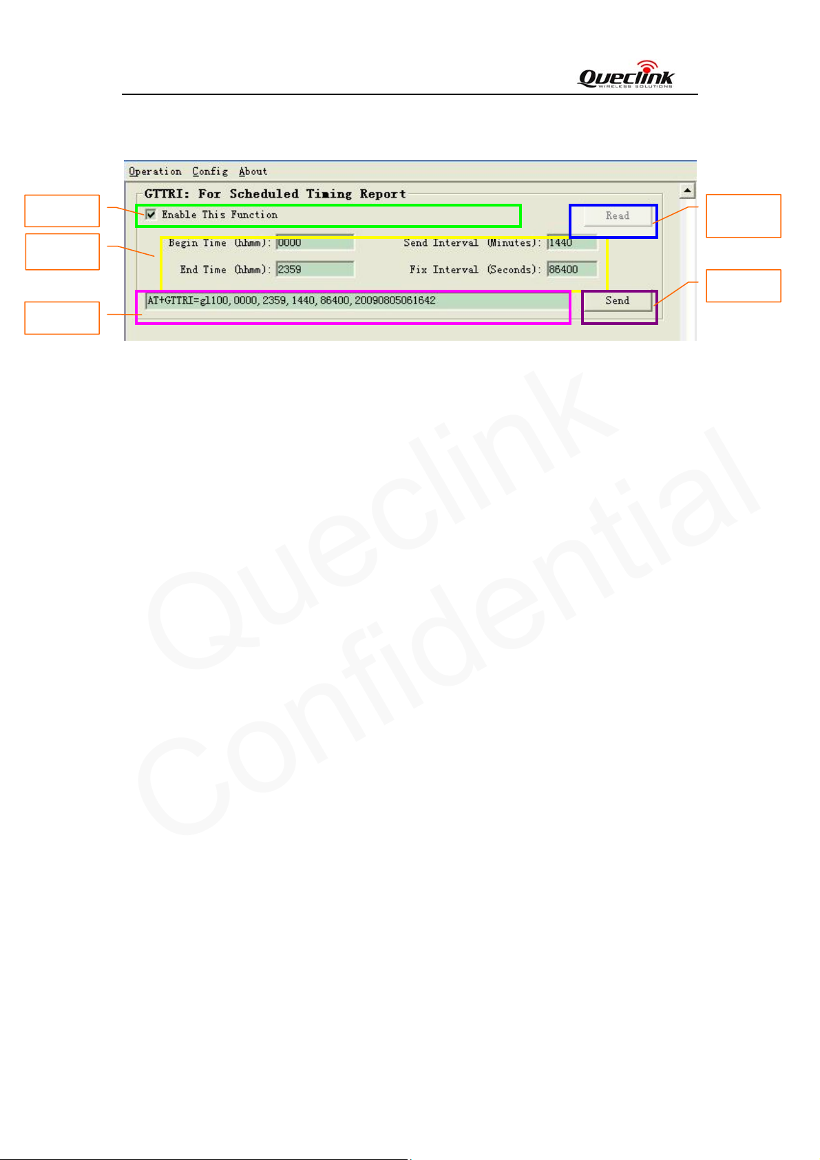
4.4.3. Set the parameters of scheduled fixed timing report
Step_1
Step_4
Step_2
Step_3
Step_5
Step_1: Select “Enable This Function”, after that the parameters of GTTRI ca n be changed and
the "Send" button is enabled.
Step_2: When “Enable This Function” is selected, the command message which shall be sent to
GL100 will be generated based on input and displayed here. Please note this command
message can also be sent to GL100 through SMS or GPRS.
Step_3: It is recommended to read the parameters from GL100 and edit based on them.
Step_4: Set the “Sta r t Tim e ”, the value range of “HH” is “00”-“23”. The value range of “MM” is
“00”-“59”.
Set the “End T ime”. The valid format and range are same as “start time”.
Set the “send interval”. It is the period to report the position information. The value range
is 0-1440 and the unit is minute.
Set the “fix interval”. It is the period to get GPS fixing, its value range is 0-86400 and the
unit is second.
Step_5: Click the “Send” button; download the parameters of GTTRI to GL100.
TRACGL100UM002 - 16 -
Page 18
GL100 User manual
Queclink
Confidential
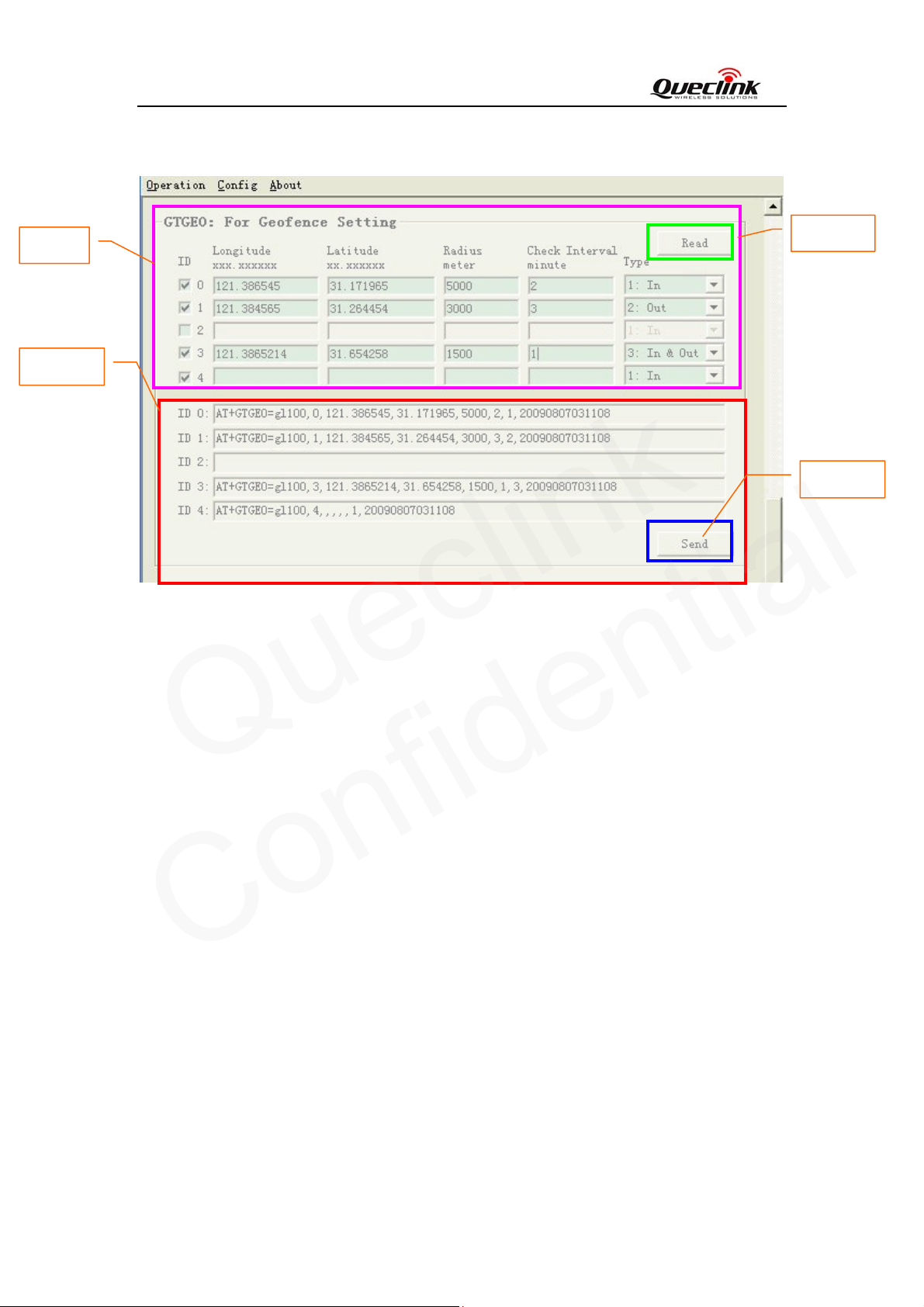
4.4.4. Set the parameters of Geo-Fence
Step_1
Step_2
Step_1: User can define up to five Geo-Fence regions on GL100. Each region is a circular area
which is defined by central coordinate and radius. When the device enters or leaves a
predefined Geo-Fence region, GL100 will send alert information to server.
“ID”: The "Send" button will be enabled when some ID check boxes are selected. After
pressing the “Send” button, the rule of selected Geo-Fences will be downloaded to
GL100.
“Latitude”: 20bytes, unit: degree, example as 31.187891 degree
“Longitude”: 20bytes, unit: degree, example as 121.412248 degree
“Radius”: 10bytes, unit: meter, example as 1000 meters.
“Check Interval”: The interval of GPS checking for Geo-Fence alarm.
“Type”: A numeric which indicates when to report the notification to backend server
about the Geo-Fence.
In: Reports when enters the Geo-Fence region.
Step_2: When “ID” check box is selected, the command message which shall be sent to GL100
will be generated based on input and displayed here. Please note this command message can also
Out: Reports when exits from the Geo-Fence region.
In & out: Reports when enters or exits from the Geo-Fence region.
Step_3
Step_4
TRACGL100UM002 - 17 -
Page 19
Step_1
Queclink
Confidential
GL100 User manual
be sent to GL100 through SMS or GPRS.
Step_3: It is recommended to read the parameters from GL100 and edit based on them.
Step_4: Click the “Send” button; download the parameters of GTGEO to GL100.
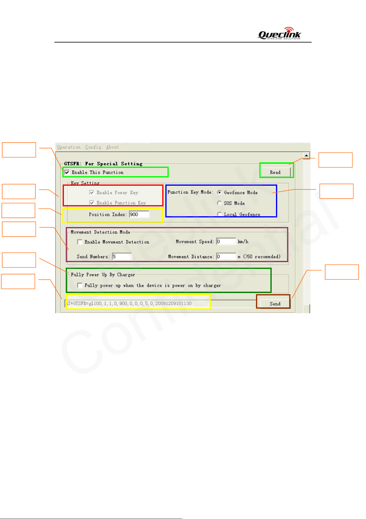
4.4.5. Set the parameters of special function
Step_3
Step_4
Step_5
Step_7
Step_8
Step_2
Step_1: Select “Enable This Function”, after that the parameters of GTSFR can be changed and
the "Send" button is enabled.
Step_2: When “Enable This Function” is selected, the command message which shall be sent to
GL100 will be generated based on input and displayed here. Please note this command
message can also be sent to GL100 through SMS or GPRS.
Step_3: It is recommended to read the parameters from GL100 and edit based on them.
Step_4: Key Setting
Set check box to enable/disable the function of buttons.
Step_5: Set the parameters of position Index. Please refer to the “GL100 @Track Air Interface
Protocol” for detail.
Step_6
Step_9
TRACGL100UM002 - 18 -
Page 20
GL100 User manual
Queclink
Confidential
Step_6: Set the mode of function key. Please refer to “GL100 @Track Air Interface Protocol” for
detail.
Step_7: Set the parameters of movement detection function. Please refer to the “GL100 @Track
Air Interface Protocol” for detail.
Step_8: “Fully Power Up By Charger”: If selected, GL100 will enter normal power-on mode even
when it is powered on by charger.
Step_9: Click the “Send” button; download the parameters of GTSFR to GL100.
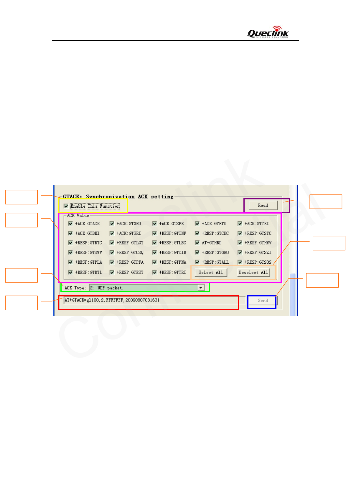
4.4.6. Set the parameters of Synchronization ACK setting
Step_1
Step_4
Step_5
Step_2
The purpose of Synchronization ACK function is to provide a way to make sure the message from
GL100 to backend server was sent successfully. Please refer to “GL100 @Track Air Interface
Protocol” for detail.
Step_1: Select “Enable This Function”, after that the parameters of GTACK can be changed and
the "Send" button is enabled.
Step_2: When “Enable This Function” is selected, the command message which shall be sent to
GL100 will be generated based on input and displayed here. Please note this command
message can also be sent to GL100 through SMS or GPRS.
Step_3: It is recommended to read the parameters from GL100 and edit based on them.
Step_4: Decide which uplink messages need Synchronization ACK. If the selected uplink
Step_3
Step_6
Step_7
TRACGL100UM002 - 19 -
Page 21
GL100 User manual
Queclink
Confidential
message is sent through the connection specified by “Ack Type”, GL100 will wait for
the Synchronization ACK message. Otherwise, GL100 won’t wait for the
Synchronization ACK message. Please refer to “GL100 @Track Air Interface Protocol”
for detail.
Step_5: Select the connection which enables Synchronization ACK mechanism. In the current
version only UDP is supported and choice 1, 4 is reserved for future use.
1: TCP packet. Not supported at present.
2: UDP packet.
4: SMS PDU. Not supported at present.
Step_6: Click “Select All” button to select all the messages if necessary.
Click “Deselect All” button to deselect all the messages if necessary.
Step_7: Click the “Send” button; download the parameters of GTACK to GL100.
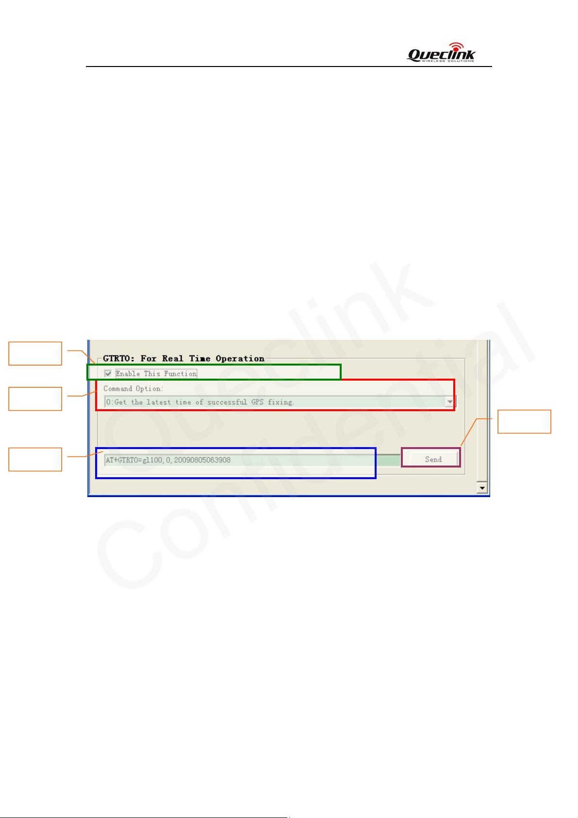
4.4.7. Real Time Operation
Step_1
Step_3
Step_2
Step_1: Select “Enable This Function”, after that the parameters of GTRTO can be changed and
the "Send" button is enabled.
Step_2: When “Enable This Function” is selected, the command message which shall be sent to
GL100 will be generated based on input and displayed here. Please note this command
message can also be sent to GL100 through SMS or GPRS.
Step_3: Select “Command Option”:
Choice 0-8, A-B is just for a dedicated action without any parameter. For the
definition, please refer to the following.
0: Get the latest time of successful GPS fixing.
1: Require the terminal to report the current position immediately
2: Get the current configuration of the terminal.
3: Reboot the terminal.
Step_4
TRACGL100UM002 - 20 -
Page 22
GL100 User manual
Queclink
Confidential
4: Reset all parameters to factory setting. Please note the following parameter will not
be reset: “report mode”, main se rver information (“main server ip”, “main server
port”, “main sms gateway”), GPRS information (“apn”, “apn user na m e ”, “apn user
password”).
5: Get the ICCID of the SIM card which is being used by the terminal.
6: Get the current GSM signal level of the terminal.
7: Get the software version.
8: Get the hardware version.
A: Get the battery level of the terminal.
B: Power off the terminal.
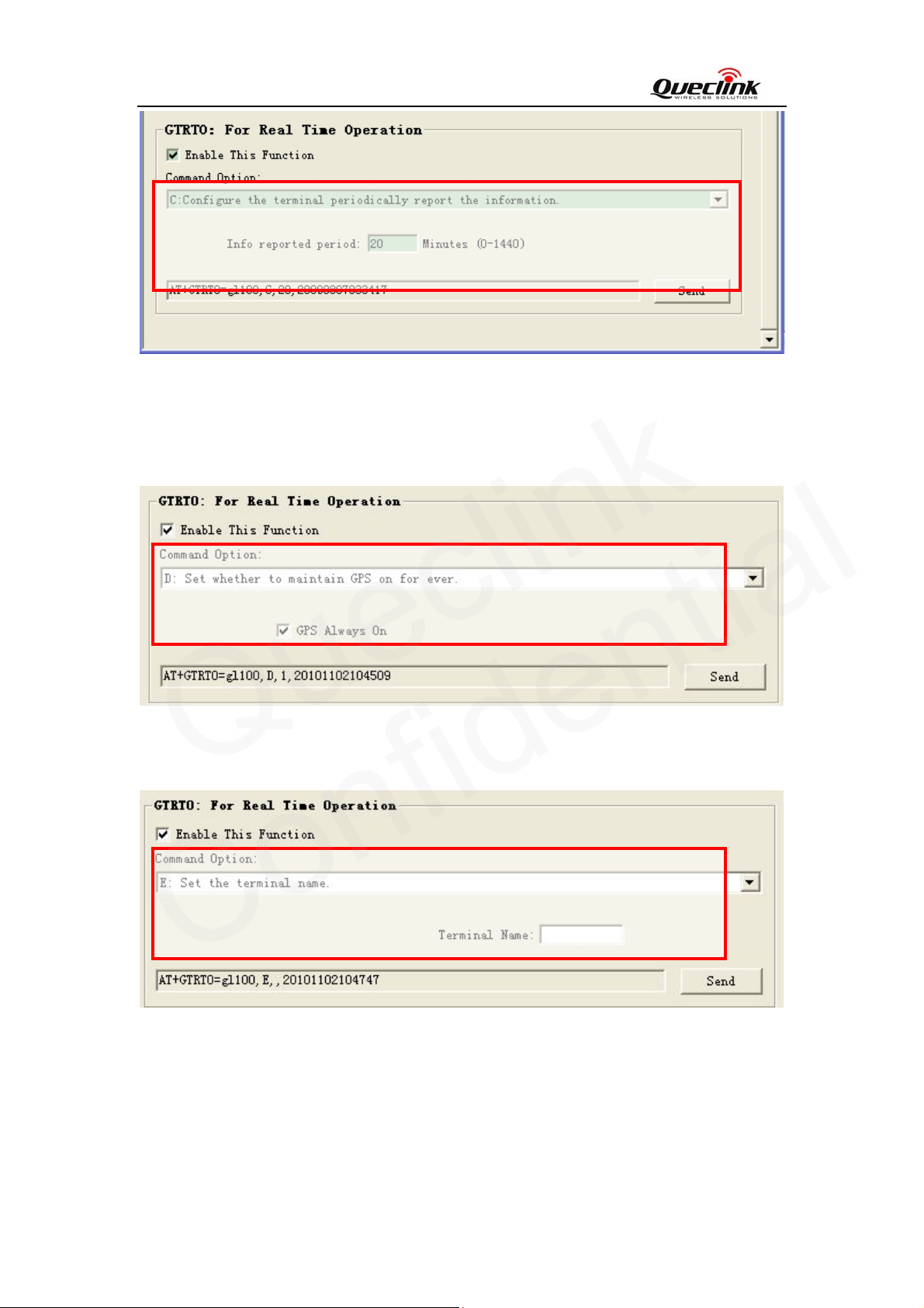
C: Configure the terminal to periodically report the information (ICCID, GSM signal
level, battery level and the status of charger). Please refer to chapter 3.3.3 for the
report message: +RESP:GTINF.
D: Set whether to maintain GPS on for ever.
E: Set the terminal name.
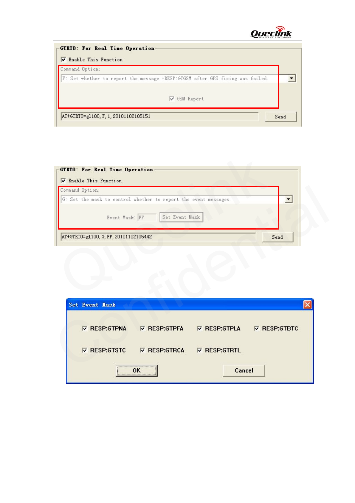
F: Set whether to report the message +RESP:GTGSM (including MCC, MNC, LAC,
CellID and signal strength of each neighbor cells and MCC, MNC, LAC, CellID,
signal strength and TA of the service cell) after the report message +RESP:GTSOS,
+RESP:GTRTL, +RESP:GTLBC and +RESP:GTTRI when GPS fixing was
failed.
G: Set the mask to control whether to report the event messages.
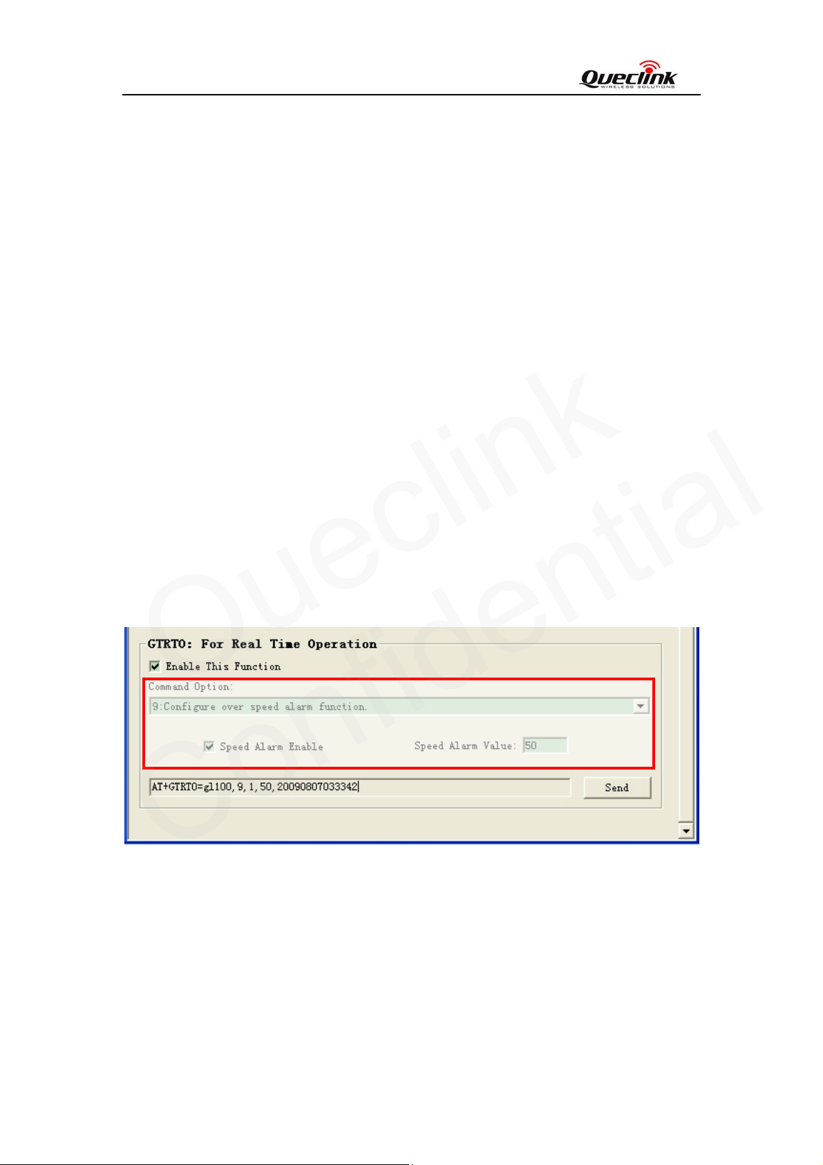
Choice 9 is used to set the parameters of over speed alarm.
“Speed Alarm Enable”: Disable or enable the over speed alarm function
“Speed Alarm Value”: When the over speed alarm function is enabled, GL100 will report to
the backend server when its speed is larger than this value.
TRACGL100UM002 - 21 -
Page 23
GL100 User manual
Queclink
Confidential
Choice C is used to configure the terminal to periodically report the information. (ICCID,
GSM signal level, battery level and the status of charging).
“Info reported period”: 0 means disable report the terminal’s information; 1-1440 means the
period of reporting, and the unit is minutes.
Choice D is used to choose whether to maintain GPS on for ever.
“gps always on”: Disable or enable GPS on for ever.
Choice E is used to set the terminal name.
“Terminal Name”: A string as the terminal name.
TRACGL100UM002 - 22 -
Page 24
GL100 User manual
Queclink
Confidential
Choice F is used to set whether to report the message +RESP:GTGSM after fixing was
failed.
“GSM Report”: Indicate whether to report the message +RESP:GTGSM.
Choice G is used to set the mask which is to control whether to report the event message.
“Event Mask”: A numeric in hex style to mask the report message. One bit represents a
message.
Click “Set Even Mask”, and select which message type you want to report by terminal in pop
box.
Step_4: Click the “Send” button; download the parameters of GTRTO to GL100.
TRACGL100UM002 - 23 -
Page 25
GL100 User manual
Queclink
Confidential
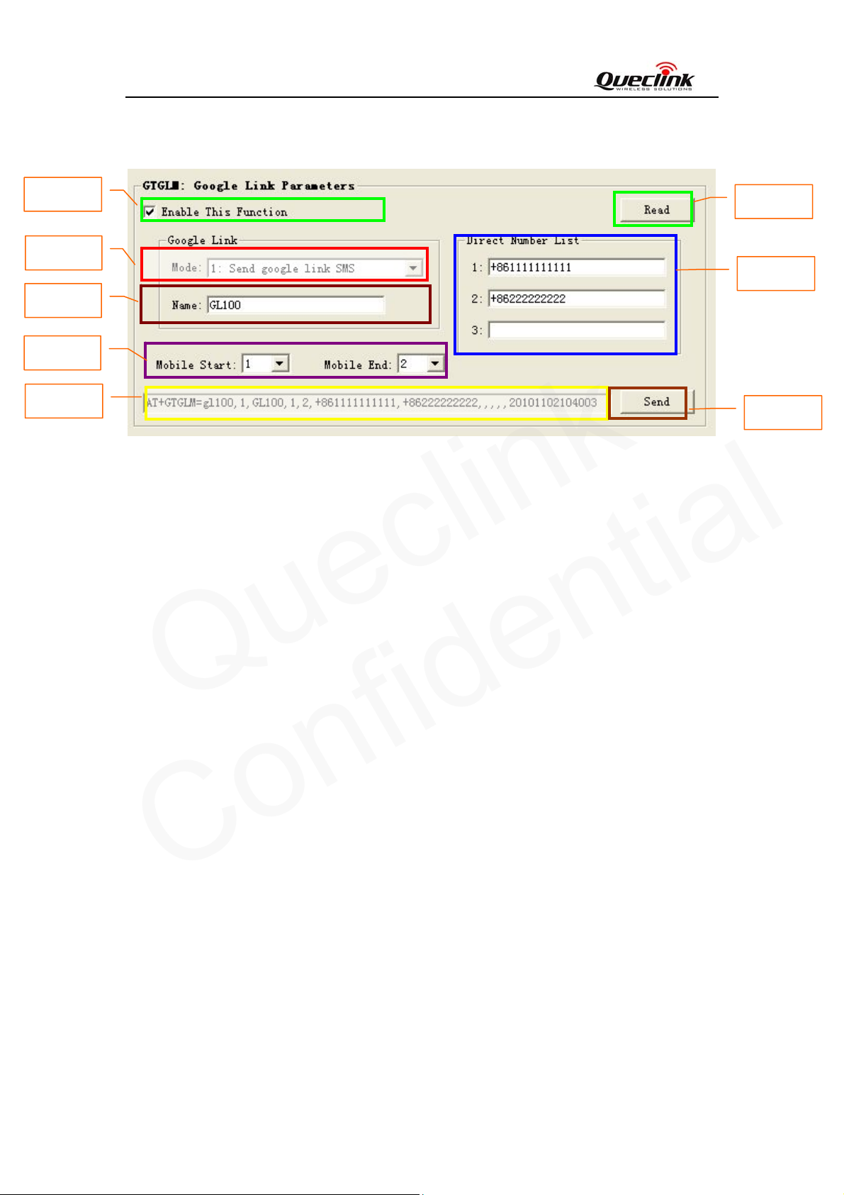
4.4.8. Set the parameters of google link function
Step_1
Step_4
Step_5
Step_6
Step_2
Step_3
Step_7
Step_8
Step_1: Select “Enable This Function”, after that the parameters of GTGLM can be changed and
the "Send" button is enabled.
Step_2: When “Enable This Function” is selected, the command message which shall be sent to
GL100 will be generated based on input and displayed here. Please note this command
message can also be sent to GL100 through SMS or GPRS.
Step_3: It is recommended to read the parameters from GL100 and edit based on them.
Step_4: Set mode of google link function. Please refer to “GL100 @Track Air Interface Protocol”
for detail.
Step_5: Set google link name. Please refer to the “GL100 @Track Air Interface Protocol” for
detail.
Step_6: Set the mobile index from start to end which you want to edit. Please refer to “GL100
@Track Air Interface Pr otocol ” for detail.
Step_7: Set the direct number list of google link. Please refer to the “GL100 @Track Air Interface
Protocol” for detail.
Step_8: Click the “Send” button; download the parameters of GTGLM to GL100.
TRACGL100UM002 - 24 -
Page 26
GL100 User manual
Queclink
Confidential
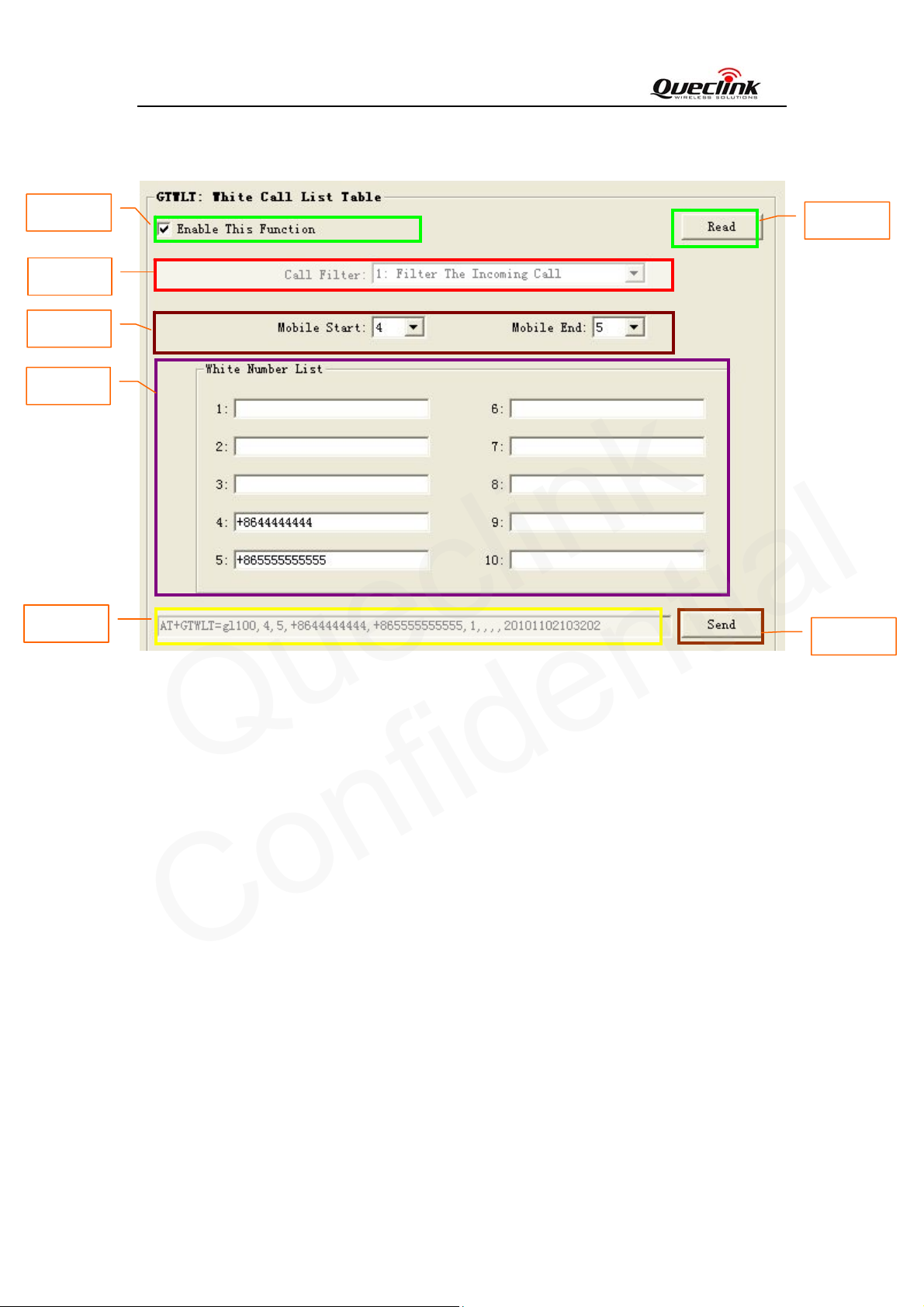
4.4.9. Set the parameters of white call list
Step_1
Step_4
Step_5
Step_6
Step_2
Step_1: Select “Enable This Function”, after that the parameters of GTWLT can be changed and
the "Send" button is enabled.
Step_2: When “Enable This Function” is selected, the command message which shall be sent to
GL100 will be generated based on input and displayed here. Please note this command
message can also be sent to GL100 through SMS or GPRS.
Step_3: It is recommended to read the parameters from GL100 and edit based on them.
Step_4: Set call filter enable or disable in white call list function. Please refer to “GL100 @Track
Air Interface Protocol” for detail.
Step_5: Set the white call list index from start to end which you want to edit. Please refer to the
“GL100 @Track Air Interface Protocol” for detail.
Step_6: Set the number list of white call list function. Please refer to “GL100 @Track Air
Interface Protocol” for detail.
Step_7: Click the “Send” button; download the parameters of GTWLT to GL100.
Step_3
Step_7
TRACGL100UM002 - 25 -
Page 27
GL100 User manual
Queclink
Confidential
5. Troubleshooting and Safety info
5.1. Troubleshooting
Trouble Possible Reason Solution
After GL100 is turned on, the
Red LED 1 flashes quickly
always.
Messages can’t be reported to
the backend server by GPRS.
Unable to power off GL100. The function of power key
The SIM card is not inserted. Please insert the SIM card into
GL100.
The signal is too weak;
GL100 can’t register to the
network.
The SIM card in GL100
doesn’t support GPRS.
APN is wrong. Some APN
can not visit the internet
directly.
The IP address or port of the
backend server is wrong.
was disabled by AT+GTSFR.
Please move GL100 into place
with good GSM coverage.
Try a GPRS supported SIM
card.
Ask the network operator for
the right APN.
Make sure the IP address for
the backend server is an
identified address in the
internet.
Enable the function of power
key by AT+GTSFR.
GL100 is turned on after insert
a charging cable.
No response from UART when
configure GL100 through
UART
GL100 can’t get successful
GPS fixing.
The function of full power up
was enabled by AT+GTSFR.
GL100 is in power saving
mode.
The GPS signal is weak.
Disable the function of full
power up by AT+GTSFR.
Remove the Data_Cable, and
plug it in again. After this
operation, GL100 will exit
from power saving mode for 10
seconds.
Please move GL100 to a place
with open sky.
It is better to let the top surface
face to sky. (The same surface
with indication LED)
GL100 will stop GPS if it can’t
get GPS fixing in 2 minutes
(except in emergency mode).
So please make sure the GPS
signal is good enough when
doing the first time of GPS
fixing.
TRACGL100UM002 - 26 -
Page 28
GL100 User manual
Queclink
Confidential
5.2. Safety info
z Please do not disassemble the device by yourself.
z Please do not put the device on the overheating or too humid place, avoid exposure to direct
sunlight. Too high temperature will damage the device or even cause the battery explosion.
z Please do not use GL100 on the airplane or near medical equipment.
TRACGL100UM002 - 27 -
 Loading...