

Page 1

AirborneDirect™ User Manual
AirborneDirect™ DP500/IN5000/HD500
Family User Manual
Revision: 1.1
February 2011
File name: user manual abdg dp5xx family v1.1
Document Number: 100-8510-110
Page 2

Quatech, Inc. AirborneDirect™ User Manual
<Page Intentionally Left Blank>
2 2/21/2011 100-8510-110
Page 3

AirborneDirect™ Users Guide Quatech, Inc.
Quatech Confidential
Copyright © 2011 QUATECH ® Inc.
ALL RIGHTS RESERVED. No part of this publication may be copied in any form, by photocopy, microfilm, retrieval
system, or by any other means now known or hereafter invented without the prior written permission of QUATECH ® Inc..
This document may not be used as the basis for manufacture or sale of any items without the prior written consent of
QUATECH Inc. is a registered trademark of QUATECH Inc..
Airborne™ and AirborneDirect™ are trademarks of QUATECH Inc..
All other trademarks used in this document are the property of their respective owners.
The information in the document is believed to be correct at the time of print. The reader remains responsible for the
system design and for ensuring that the overall system satisfies its design objectives taking due account of the information
presented herein, the specifications of other associated equipment, and the test environment.
QUATECH ® Inc. has made commercially reasonable efforts to ensure that the information contained in this document is
accurate and reliable. However, the information is subject to change without notice. No responsibility is assumed by
QUATECH for the use of the information or for infringements of patents or other rights of third parties. This document is
the property of QUATECH ® Inc. and does not imply license under patents, copyrights, or trade secrets.
QUATECH Inc..
Disclaimer
Quatech, Inc. Headquarters
QUATECH ® Inc..
5675 Hudson Industrial Parkway
Hudson, OH 44236
USA
Telephone: 330.655.9000
Toll Free (USA): 800.553.1170
Fax: 330.655.9010
Technical Support: 800.553.1170 / support@quatech.com
Web Site: www.quatech.com
100-8510-110 2/21/2011 3
Page 4

Quatech, Inc. AirborneDirect™ User Manual
<Page Intentionally Left Blank>
4 2/21/2011 100-8510-110
Page 5

AirborneDirect™ Users Guide Quatech, Inc.
Contents
1.0 Conventions ....................................................................................................................................................... 9
1.1 Terminology ................................................................................................................................................... 9
1.2 Notes .............................................................................................................................................................. 9
1.3 Caution ........................................................................................................................................................... 9
1.4 File Format ..................................................................................................................................................... 9
2.0 Product Description .......................................................................................................................................... 10
3.0 Features .......................................................................................................................................................... 11
4.0 Device Types ................................................................................................................................................... 12
4.1 Serial ............................................................................................................................................................ 12
4.2 Ethernet ....................................................................................................................................................... 12
4.3 Serial + Ethernet........................................................................................................................................... 12
4.4 Enterprise Class ........................................................................................................................................... 13
4.5 Industrial Class ............................................................................................................................................. 13
4.6 Heavy Duty Class ......................................................................................................................................... 14
5.0 Block Diagram ................................................................................................................................................. 16
6.0 Pin out and Connectors .................................................................................................................................... 18
6.1 Serial Ports ................................................................................................................................................... 18
6.2 Ethernet Port ................................................................................................................................................ 19
6.3 Connector Definition ..................................................................................................................................... 20
6.4 OEM Reset Switch (Factory Reset) .............................................................................................................. 20
6.5 Enterprise Serial Interface Jumpers .............................................................................................................. 21
6.6 Indicator LED’s ............................................................................................................................................. 22
7.0 Electrical & RF Specification ............................................................................................................................ 24
7.1 AC Electrical Characteristics – Transmitter ................................................................................................... 26
7.2 Performance/Range ..................................................................................................................................... 26
8.0 Antenna ........................................................................................................................................................... 27
8.1 Antenna Selection ........................................................................................................................................ 27
8.2 Host Board Mounted Antenna....................................................................................................................... 27
8.3 Host Chassis Mounted Antenna ................................................................................................................... 28
8.4 Embedded Antenna ...................................................................................................................................... 28
8.5 Antenna Location ......................................................................................................................................... 29
8.6 Performance ................................................................................................................................................. 30
9.0 Mechanical Outline – Enterprise Class ............................................................................................................. 32
10.0 Mechanical Outline – Industrial Class............................................................................................................... 33
11.0 Getting Started ................................................................................................................................................. 34
11.1 Unpack the AirborneDirect™ Device ............................................................................................................ 34
11.2 Connect AirborneDirect™ to host ................................................................................................................. 34
11.3 Attach Antenna and Power-up the AirborneDirect™ ..................................................................................... 34
12.0 Configuring Device – Industrial Serial (ABDG-SE-IN5XXX) .............................................................................. 35
13.0 Configuring Device – Enterprise Serial (ABDG-SE-DP5XX) ............................................................................. 38
13.1 Connect a Host Computer ............................................................................................................................ 38
13.2 Interacting with the AirborneDirect™ device ................................................................................................. 38
13.3 Determine and Store the Access Point SSID ................................................................................................ 39
13.4 Determine the Device’s IP address ............................................................................................................... 39
13.5 Accessing the Device Using the Web Interface ............................................................................................. 40
13.6 Accessing the Device Using Telnet .............................................................................................................. 40
14.0 Configuring Device – Enterprise/Industrial Ethernet ......................................................................................... 41
15.0 Using the Web Interface ................................................................................................................................... 44
15.1 Navigation Bar .............................................................................................................................................. 45
15.2 Feature Links ............................................................................................................................................... 46
15.3 Navigating the Website ................................................................................................................................. 46
15.4 Updating a Field ........................................................................................................................................... 47
15.5 Uploading Certificates .................................................................................................................................. 48
15.6 Upload Configuration Files ........................................................................................................................... 48
15.7 Updating Firmware ....................................................................................................................................... 50
16.0 Express Setup Configuration Page .................................................................................................................. 53
17.0 Configuring the Wireless Interface ................................................................................................................... 56
17.1 Configuring for Infrastructure Networks ........................................................................................................ 56
17.2 Configuring for AdHoc Networks ................................................................................................................... 56
18.0 Configuring the Security Settings ..................................................................................................................... 58
18.1 Configuring for WEP Security ....................................................................................................................... 58
18.2 Configuring for WPA-PSK Security ............................................................................................................... 59
18.3 Configuring for WPA2-PSK Security ............................................................................................................. 60
18.4 Configuring for PEAP Security ...................................................................................................................... 61
19.0 Configuring Network Settings ........................................................................................................................... 63
19.1 Configuring DHCP on WLAN Interface ......................................................................................................... 63
19.2 Configuring DHCP on Ethernet Interface ...................................................................................................... 64
19.3 Configuring a Static IP Address on WLAN Interface ..................................................................................... 65
100-8510-110 2/21/2011 5
Page 6

Quatech, Inc. AirborneDirect™ User Manual
19.4 Configuring a Static IP Address on Ethernet Interface .................................................................................. 66
20.0 Configuring Serial Device Server ..................................................................................................................... 68
20.1 Configuring Serial Port for Access on Telnet Port ......................................................................................... 68
20.2 Configuring Serial Port 1 for Access on Tunnel Port ..................................................................................... 69
20.3 Configuring Serial Port 2 for Access on Tunnel Port ..................................................................................... 71
20.4 Configuring Serial Port 1 as TCP Client ................................ ........................................................................ 72
20.5 Configuring Serial Port 2 as TCP Client ................................ ........................................................................ 73
21.0 Installing and Using the Airborne VirtualCOM Driver ........................................................................................ 75
22.0 Replacing a Serial Cable .................................................................................................................................. 78
23.0 Configuring Ethernet Adapter ........................................................................................................................... 81
23.1 Public Network Interface ............................................................................................................................... 82
23.2 Private Network Interface ............................................................................................................................. 83
24.0 Web Page Overview ........................................................................................................................................ 87
Module Status ........................................................................................................................................................ 88
Ethernet Status ...................................................................................................................................................... 89
Ethernet DHCP Clients........................................................................................................................................... 90
Radio Statistics ...................................................................................................................................................... 91
Ethernet Statistics .................................................................................................................................................. 92
Express Setup ........................................................................................................................................................ 93
WLAN Settings ....................................................................................................................................................... 95
WLAN Security Settings ......................................................................................................................................... 96
Network Settings .................................................................................................................................................... 98
Serial Port Settings .............................................................................................................................................. 100
Serial Port 2 Settings ........................................................................................................................................... 101
Connection Settings ............................................................................................................................................. 102
Ethernet Settings.................................................................................................................................................. 104
Wireless Routing Settings .................................................................................................................................... 105
Ethernet Routing Settings .................................................................................................................................... 106
Advanced Settings ............................................................................................................................................... 107
Upload Configuration File ..................................................................................................................................... 110
List Configuration File .......................................................................................................................................... 111
Delete Configuration File ...................................................................................................................................... 112
Active Configuration ............................................................................................................................................. 113
User Configuration ............................................................................................................................................... 114
OEM Configuration ............................................................................................................................................... 115
Factory Configuration ........................................................................................................................................... 116
WPA Configuration ............................................................................................................................................... 117
List Certificates .................................................................................................................................................... 118
Upload Certificate................................................................................................................................................. 119
Delete Certificate.................................................................................................................................................. 120
Network (Home Page) .......................................................................................................................................... 121
Discover Airborne Modules .................................................................................................................................. 122
Scan for Access Points ........................................................................................................................................ 123
Maintenance (Home Page) .................................................................................................................................. 124
Update Module Firmware ..................................................................................................................................... 125
Reset Factory Defaults ......................................................................................................................................... 126
Restart Module ..................................................................................................................................................... 127
Blink the POST LED ............................................................................................................................................. 128
Stop Blinking the POST LED ................................................................................................................................ 129
Change Module Personality ................................................................................................................................. 130
25.0 Certification & Regulatory Approvals .............................................................................................................. 131
25.1 FCC Statement ........................................................................................................................................... 131
25.2 FCC RF Exposure Statement ..................................................................................................................... 131
25.3 Information for Canadian Users (IC Notice) ................................................................................................ 132
25.4 FCC/IC Modular Approval ........................................................................................................................... 132
25.5 Regulatory Test Mode Support ................................................................................................................... 133
26.0 Physical & Environmental Approvals .............................................................................................................. 134
27.0 Change Log ................................................................................................................................................... 135
6 2/21/2011 100-8510-110
Page 7

AirborneDirect™ Users Guide Quatech, Inc.
Figures
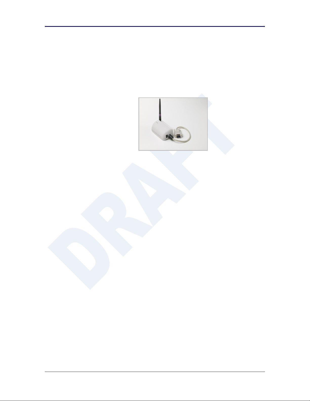
Figure 1 - Enterprise AirborneDirect™ Device ................................................................................................................. 13
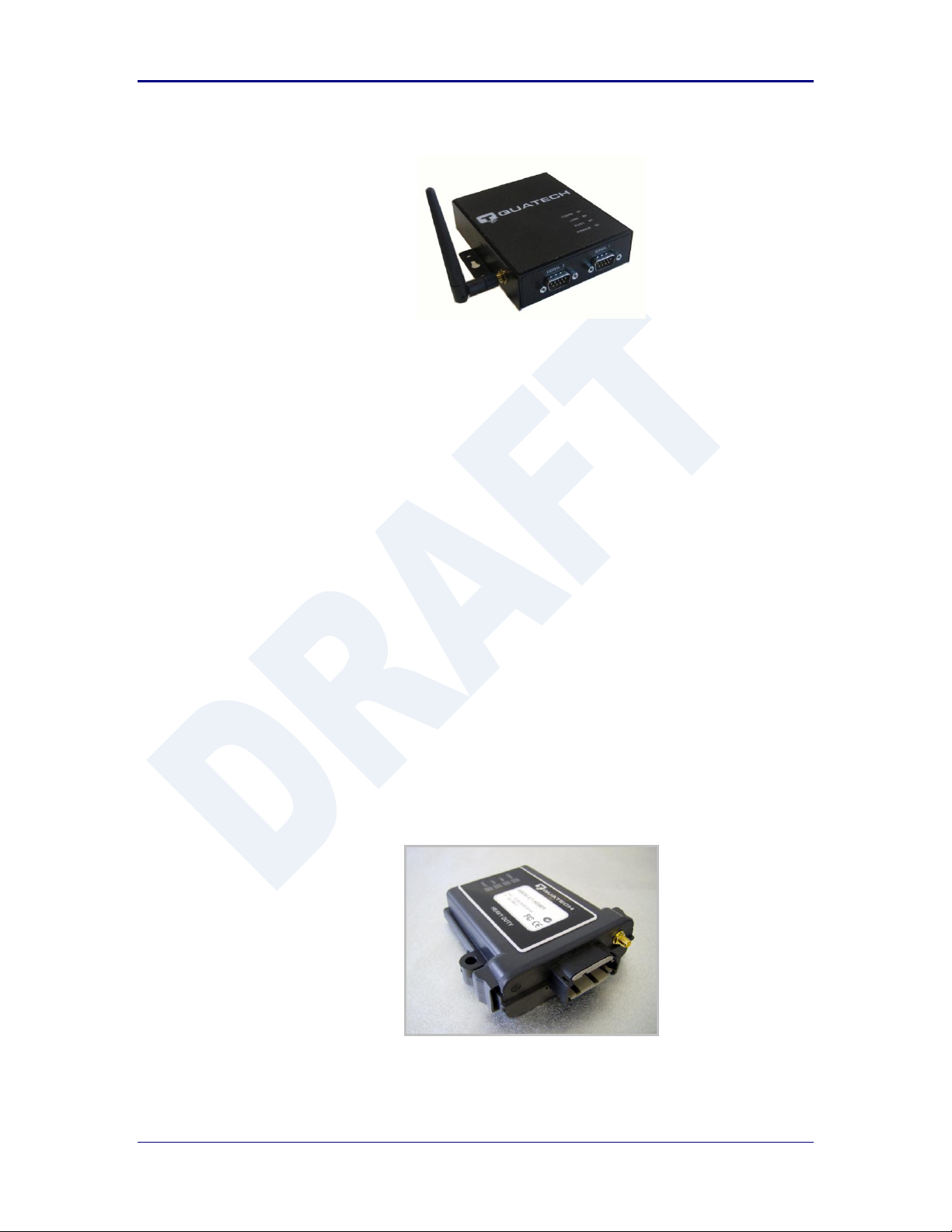
Figure 2 - Industrial AirborneDirect™ Device ................................................................................................................... 14
Figure 3 - Heavy Duty AirborneDirect™ Device ............................................................................................................... 14
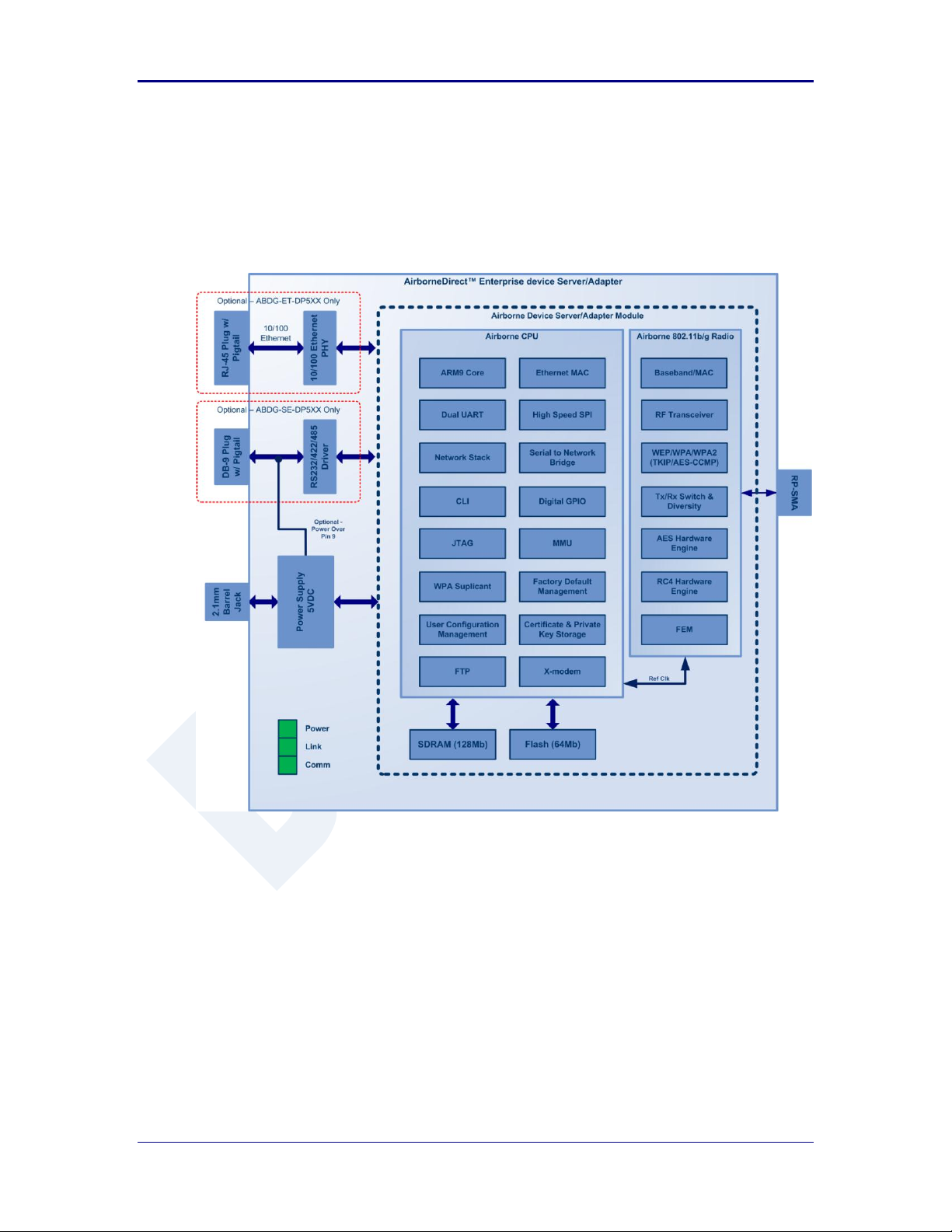
Figure 4 - ABDG-SE/ET-DP5XX Block Diagram .............................................................................................................. 16
Figure 5 - ABDG-ET/SE-IN5XXX Block Diagram ............................................................................................................. 17
Figure 6 - DE-9 (DB-9) Connector Pin-out........................................................................................................................ 18
Figure 7 - Ethernet Jack Pin Out ...................................................................................................................................... 19
Figure 8- Interface Selection Jumpers.............................................................................................................................. 21
Figure 9 - Website Login .................................................................................................................................................. 44
Figure 10 - Default Home Page ....................................................................................................................................... 45
Figure 11 - Website Navigation Bar ................................................................................................................................. 45
Figure 12- Feature Links .................................................................................................................................................. 46
Figure 13 - Airborne Web Page ....................................................................................................................................... 47
Figure 14 - upload Certificate Web page .......................................................................................................................... 48
Figure 15 - Upload Configuration Web Page .................................................................................................................... 49
Figure 16 - Firmware Update Page .................................................................................................................................. 50
Figure 17 - Firmware Update in Progress ........................................................................................................................ 51
Figure 18 - Firmware Update Complete ........................................................................................................................... 51
Figure 19 - Express Setup Page ...................................................................................................................................... 53
Figure 20 - Ethernet Bridge Functionality ......................................................................................................................... 81
Figure 21 - Airborne Ethernet Bridge IP Configuration ..................................................................................................... 83
Tables
Table 1 – Serial Port Pin Definition .................................................................................................................................. 18
Table 2 - Serial Ports by Product Class ............................................................................................................................ 19
Table 3 - Ethernet Connector Pin Out .............................................................................................................................. 19
Table 4 - Connector Description....................................................................................................................................... 20
Table 5 - OEM Reset Procedure ...................................................................................................................................... 21
Table 6 - Enterprise LED Indicators ................................................................................................................................. 22
Table 7 - Industrial LED Indicators ................................................................................................................................... 23
Table 8- Absolute Maximum Values1 ............................................................................................................................... 24
Table 9 - RF Characteristics – 802.11b/g ......................................................................................................................... 24
Table 10 - Supported Data Rates by Band ....................................................................................................................... 25
Table 11 - Operating Channels ........................................................................................................................................ 25
Table 12 - Radio Typical Performance Range .................................................................................................................. 26
Table 13 - Embedded Antenna Options ........................................................................................................................... 28
Table 14 - SE-IN5XXX Accessing the Web Interface ....................................................................................................... 35
Table 15 - UART Authentication....................................................................................................................................... 38
Table 16 - UART SSID & Authentication .......................................................................................................................... 39
Table 17 - UART Determine Module's IP Address ........................................................................................................... 39
Table 18 - ET-DP5XX/IN5XXX Accessing the Web Interface ........................................................................................... 41
Table 19 - Navigation Bar Items ....................................................................................................................................... 45
Table 20 - Uploading Certificates ..................................................................................................................................... 48
Table 21 - Uploading Configurations ................................................................................................................................ 49
Table 22 - Updating Firmware .......................................................................................................................................... 51
Table 23 - Express Page Setup ....................................................................................................................................... 53
Table 24 - Configuring Wireless Interface - Infrastructure ................................................................................................ 56
Table 25 - Configuring Wireless Interface - AdHoc ........................................................................................................... 57
Table 26 - Configuring for WEP Security .......................................................................................................................... 58
Table 27 - Configuring for WPA Security .......................................................................................................................... 59
Table 28 - Configuring for WPA2 Security ........................................................................................................................ 60
Table 29 - Configuring for PEAP Security ........................................................................................................................ 61
Table 30 - Configuring DHCP - WLAN ............................................................................................................................. 63
Table 31 - Configuring DHCP - Ethernet .......................................................................................................................... 64
Table 32 - Configuring Static IP - WLAN .......................................................................................................................... 65
Table 33 - Configuring Static IP - Ethernet ................................................................................................ ....................... 66
Table 34 – Configure Data Tunnel on Telnet Port ............................................................................................................ 68
Table 35 - Data Tunnel using Telnet Port ......................................................................................................................... 69
Table 36 – Configure Data Tunnel on Serial Port 1 Tunnel Port (TCP) ............................................................................. 70
Table 37 - Data Tunnel using Tunnel Port on Serial Port 1............................................................................................... 70
Table 38 – Configure Data Tunnel on Serial Port 2 Tunnel Port (TCP) ............................................................................. 71
Table 39 - Data Tunnel using Tunnel Port on Serial Port 2............................................................................................... 72
Table 40 - Configure Serial Port 1 as TCP Client ............................................................................................................. 72
Table 41 - Configure Serial Port 2 as TCP Client ............................................................................................................. 73
Table 42 - Install VCOM ................................................................................................................................................... 75
Table 43 - Cable Replacement - Slave Configuration ....................................................................................................... 78
100-8510-110 2/21/2011 7
Page 8

Quatech, Inc. AirborneDirect™ User Manual
Table 44 - Cable Replacement - Master Configuration ..................................................................................................... 79
Table 45 - Ethernet Adapter interface Configuration - DHCP ........................................................................................... 83
Table 46 - Ethernet Adapter interface Configuration - Static IP ........................................................................................ 84
Table 47 - Regulatory Approvals .................................................................................................................................... 131
Table 48 - Modular Approval Grant Numbers ................................................................................................................. 132
Table 49 - Mechanical Approvals ................................................................................................................................... 134
8 2/21/2011 100-8510-110
Page 9

AirborneDirect™ Users Guide Quatech, Inc.
The area next to the indicator will identify the specific information and make any
references necessary.
The area next to the indicator will identify the specific information and make any
references necessary.
1.0 Conventions
The following section outlines the conventions used within the document, where
convention is deviated from the deviation takes precedence and should be followed. If
you have any question related to the conventions used or clarification of indicated
deviation please contact Quatech Sales or Wireless Support.
1.1 Terminology
Airborne Enterprise Device Server and AirborneDirect Enterprise Device
Server is used in the opening section to describe the devices detailed in this
document, after this section the term module will be used to describe the
devices.
1.2 Notes
A note contains information that requires special attention. The following
convention will be used. The area next to the indicator will identify the specific
information and make any references necessary.
1.3 Caution
A caution contains information that, if not followed, may cause damage to the
product or injury to the user. The shaded area next to the indicator will identify
the specific information and make any references necessary.
1.4 File Format
These documents are provided as Portable Document Format (PDF) files. To
read them, you need Adobe Acrobat Reader 4.0.5 or higher. For your
convenience, Adobe Acrobat Reader is provided on the Radio Evaluation Kit CD.
Should you not have the CD, for the latest version of Adobe Acrobat Reader, go
to the Adobe Web site (www.adobe.com).
100-8510-110 2/21/2011 9
Page 10

Quatech, Inc. AirborneDirect™ User Manual
2.0 Product Description
This guide describes the AirborneDirect™ device servers and wireless adapters from
Quatech, Inc. AirborneDirect™ is a fully integrated, 802.11 wireless Local Area Network
(LAN) connectivity device designed to provide wireless LAN and Internet connectivity in
industrial, scientific, medical, and transportation applications where an existing
communications interface already exists. The AirborneDirect family of products supports
Serial (RS232/422/485), Ethernet and a combination these interfaces in a range of
packaging options.
The AirborneDirect™ product family provides true plug-and-play wireless connectivity. By
delivering convenient, easy-to-deploy wireless network connectivity, the device servers
and adapters significantly reduce the complexities of wireless system deployment and
network implementation. At the same time, users can move equipment without the cost
and time associated with wired network drops and environment restrictions. This provides
flexibility for seasonal demands, line and staffing changes, and more.
The AirborneDirect™ Serial Bridges and device servers provide a simple connection
between the 802.11 wireless LAN and three leading serial interfaces: RS-232, RS-422,
and RS-485. The Bridge acts transparently between any device using these interfaces
and a wireless LAN. Using the Quatech virtual communications port Windows device
driver OEMs can communicate with their devices from any workstation on the same
network as if the workstation and devices were directly attached through a serial port.
The AirborneDirect™ Ethernet Adapter provides a link between the 802.11 wireless LAN
and any Ethernet-ready device with an RJ-45 connector. It acts transparently between
the device and a wireless LAN. By integrating AirborneDirect™ into existing and legacy
platforms, OEMs can significantly enhance their products by delivering increased value
and functionality to their entire customer base.
The Airborne family includes the ability to simultaneously use the serial-to-wireless and
Ethernet-to-wireless connectivity in the same unit. This capability provides for multiple
connections to the same machine or consolidation of multiple wireless units into a single
device.
The AirborneDirect™ products open the world of remote device monitoring and
management, as well as wide-area data collection, to any device, machine, or plant that
has an external serial or Ethernet connection and a network infrastructure. The
development kit provides quick and easy access to the Bridge’s configuration and
functions, while providing OEMs with a platform to develop their branded solutions. The
Bridge also provides the capability to perform firmware upgrades that allow new features
to be added quickly and easily, protecting your investment.
The Enterprise family includes the most advanced security support available for the
device class in the industry, including WPA, WPA2 and full Enterprise support. The
devices can be used with the most advanced WLAN networks being deployed today. The
Airborne products are based upon the industry leading Airborne device server and
wireless adapter technology from Quatech, providing a fully compatible and familiar
device interface across the all product ranges. If you’ve used one you have used them
all.
10 2/21/2011 100-8510-110
Page 11

AirborneDirect™ Users Guide Quatech, Inc.
3.0 Features
802.11b/g WiFi Radio with 32bit ARM9 CPU (128Mb SDRAM, 64Mb Flash)
Integrated Airborne Device Server and Wireless Adapter technology.
Supports WEP, WPA, WPA2 and 802.1x Supplicant, with Certificates.
The wireless device server includes integrated:
802.11b/g radio driver
TCP/IP stack, UDP, telnet, FTP server
Data bridging and buffering
Command Line Interface
Web interface
WPA Supplicant
802.11 Radio Driver
DHCP Server (Ethernet Interface)
Firewall and Port Forwarding (Ethernet)
FTP Server
Supports flexible antenna selection.
Operating Temperature (-40°C to 85°C)
Storage temp (-50°C to 125°C)
Industry standard wired connections:
D-9 Serial connectors (RS232/422/485)
RJ-45 (10/100 Ethernet)
Multiple host interfaces supported:
Single and Dual Serial (RS232/422/485) – up to 921K BAUD
10/100 Ethernet
Integrated standard and wide range (J1455) Power Supply (5-36VDC)
Power connector options include 2.1mm Barrel Jack, Terminal Block and
custom connectors.
Integrated Site Survey mode.
Advanced Low power modes.
Rugged mounting options.
Virtual COM port driver (WinXP, Vista, Win7)
Worldwide Regulatory Support (FCC, IC, CE)
100-8510-110 2/21/2011 11
Page 12

Quatech, Inc. AirborneDirect™ User Manual
4.0 Device Types
This manual covers all variations available in the AirborneDirect™ device family. The
following section identifies the different types both functional and classification. In most
cases the functional types are available in the listed classifications. If you are not certain
which type you have or would like clarify the available options please contact Quatech
Sales or Technical support.
4.1 Serial
This device supports a single or dual serial port and provides serial to 802.11
bridging. The serial devices can support one or more of the following serial
interface types:
RS232
RS422
RS485
Default configuration on all models is RS232, conversion to RS422/485 requires
software configuration and in some models jumper setting changes. These are
covered in the following sections.
This device allows the connection of a serial port to an 802.11 network.
4.2 Ethernet
The Ethernet adapter provides a wireless interface to an existing Ethernet port
(RJ-45). Depending upon the model of device the connection to the Ethernet port
of the host is made via a RJ-45 socket or pigtail with a RJ-45 plug.
The device supports a 10/100 Ethernet interface with auto configuration. Manual
control of the interface is possible through the web or CLI interface.
4.3 Serial + Ethernet
This device allows for simultaneous connection of Serial and Ethernet ports.
Providing the same functionality on each port that is available on the individual
devices, it is possible to maintain network based connections to both the
Ethernet and Serial ports without compromise of functionality or performance.
Each interface can be configured and operated independently of the others.
Connection to the serial port can be made via both the wireless and Ethernet
ports supporting redundant network connectivity for high reliability applications.
12 2/21/2011 100-8510-110
Page 13
AirborneDirect™ Users Guide Quatech, Inc.
4.4 Enterprise Class
The enterprise class product provides the best cost vs. performance in the
AirborneDirect™ product family. The packaging is compact and designed to fit
with non-industrial applications and markets. The product class supports the full
industrial operating temperature range and the complete set of functional
capabilities of the Airborne™ Device Server and Wireless Adapter technology.
Figure 1 - Enterprise AirborneDirect™ Device
The Enterprise class product range includes devices that support a single serial
port and an Ethernet device.
The enterprise class product is ideal for the following application types:
Medical equipment.
Point-of-Sale devices.
CNC/DNC equipment.
Time clocks.
Scales.
Data collection devices.
Vehicle diagnostics.
The Enterprise Class products require a 5VDC power supply.
4.5 Industrial Class
Developed to support the demands of the industrial and automotive
environments, the features of the Industrial Class products offer a more flexible
and rugged alternative to the enterprise class devices. The product class
supports the full industrial operating temperature range and the complete set of
functional capabilities of the Airborne Device Server and Wireless Adapter
technology.
100-8510-110 2/21/2011 13
Page 14
Quatech, Inc. AirborneDirect™ User Manual
Figure 2 - Industrial AirborneDirect™ Device
The family includes a metal enclosure and a wide range power supply capable of
exceeding the SAE J1455 power supply requirements.
The enterprise class product is ideal for the following application types:
CNC/DNC equipment.
Vehicle diagnostics.
Telematics.
Remote monitoring and management.
Industrial control.
The Industrial class of products includes Ethernet only, Serial only and the dual
(Serial+Ethernet) capability.
4.6 Heavy Duty Class
These are the highest performing and most rugged Serial Device Server and
Ethernet adapter products in the market. The Heavy Duty product class supports
the highest level of ruggedization available allowing use in the most hazardous
and demanding environments. The product class supports the full industrial
operating temperature range and the complete set of functional capabilities of the
Airborne Device Server and Wireless Adapter technology.
Figure 3 - Heavy Duty AirborneDirect™ Device
The product family uses the Deutsch EEC-325X4B enclosure with sealed and
vented variations and a wide range power supply, capable of exceeding the SAE
J1455 power supply requirements.
14 2/21/2011 100-8510-110
Page 15

AirborneDirect™ Users Guide Quatech, Inc.
The Heavy Duty products are ideal for the following applications:
Mining equipment telematics.
Military vehicle diagnostics.
Avionics.
Construction heavy equipment diagnostics.
The HD class of products includes Ethernet only, Serial only and the dual
(Serial+Ethernet) capability, through a custom Deutsch connector (DTM06128A).
100-8510-110 2/21/2011 15
Page 16
Quatech, Inc. AirborneDirect™ User Manual
5.0 Block Diagram
The following outlines the block diagram for the devices:
Figure 4 - ABDG-SE/ET-DP5XX Block Diagram
16 2/21/2011 100-8510-110
Page 17
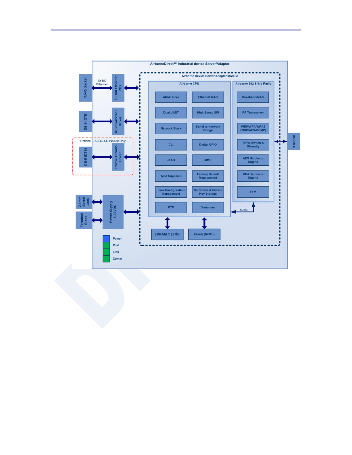
AirborneDirect™ Users Guide Quatech, Inc.
Figure 5 - ABDG-ET/SE-IN5XXX Block Diagram
100-8510-110 2/21/2011 17
Page 18
Quatech, Inc. AirborneDirect™ User Manual
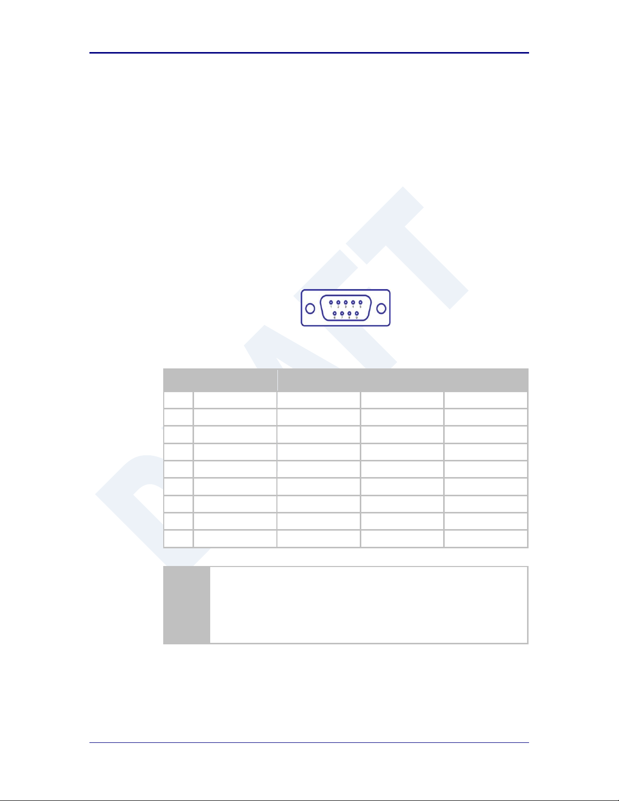
Pin
RS232 (DTE)
RS232 w/
Power on pin 9
2
RS422
RS485
1
No Connect
No Connect
No Connect
No Connect
2
RxD
RxD
RxD+
Connect to pin 33
3
TxD
TxD
TxD+
TxD+/RxD+
4
No Connect
No Connect
No Connect
No Connect
5
GND
GND
GND
GND
6
No Connect
No Connect
RxD-
Connect to pin 93
7
RTS
RTS
No Connect
No Connect
8
CTS
CTS
No Connect
No Connect
9
No Connect
5VDC (Input)
TxD-
TxD-/RxD-
1. For 2-wire operation, the user must externally connect pin 3 to pin 2 and
pin 6 to pin 9.
2. Power on pin 9 only available on Enterprise devices (ABDG-SE-DP501).
3. Only required on Industrial products (ABDG-SE-IN54XX)
6.0 Pin out and Connectors
Pin definition is dependent upon the device type selected. The following defines the pin
outs for the individual interfaces.
6.1 Serial Ports
The AirborneDirect™ units support either a single or dual serial port
configuration. The Port pin out can change depending upon the interface
configuration chosen, Table 1 shows the pin out for the interface selected.
Figure 6 - DE-9 (DB-9) Connector Pin-out
Table 1 – Serial Port Pin Definition
Table 2 shows the availability of the serial ports and available interface types by
product class.
18 2/21/2011 100-8510-110
Page 19
AirborneDirect™ Users Guide Quatech, Inc.
Device Class
Port 1
Port 2
Enterprise
RS232
RS422 (4-wire)
RS485 (2-wire)
N/A
Industrial
RS232
RS422 (4-wire)
RS485(2-wire)
N/A
RS232
RS422 (4-wire)
RS485(2-wire)
RS232
RS422 (4-wire)
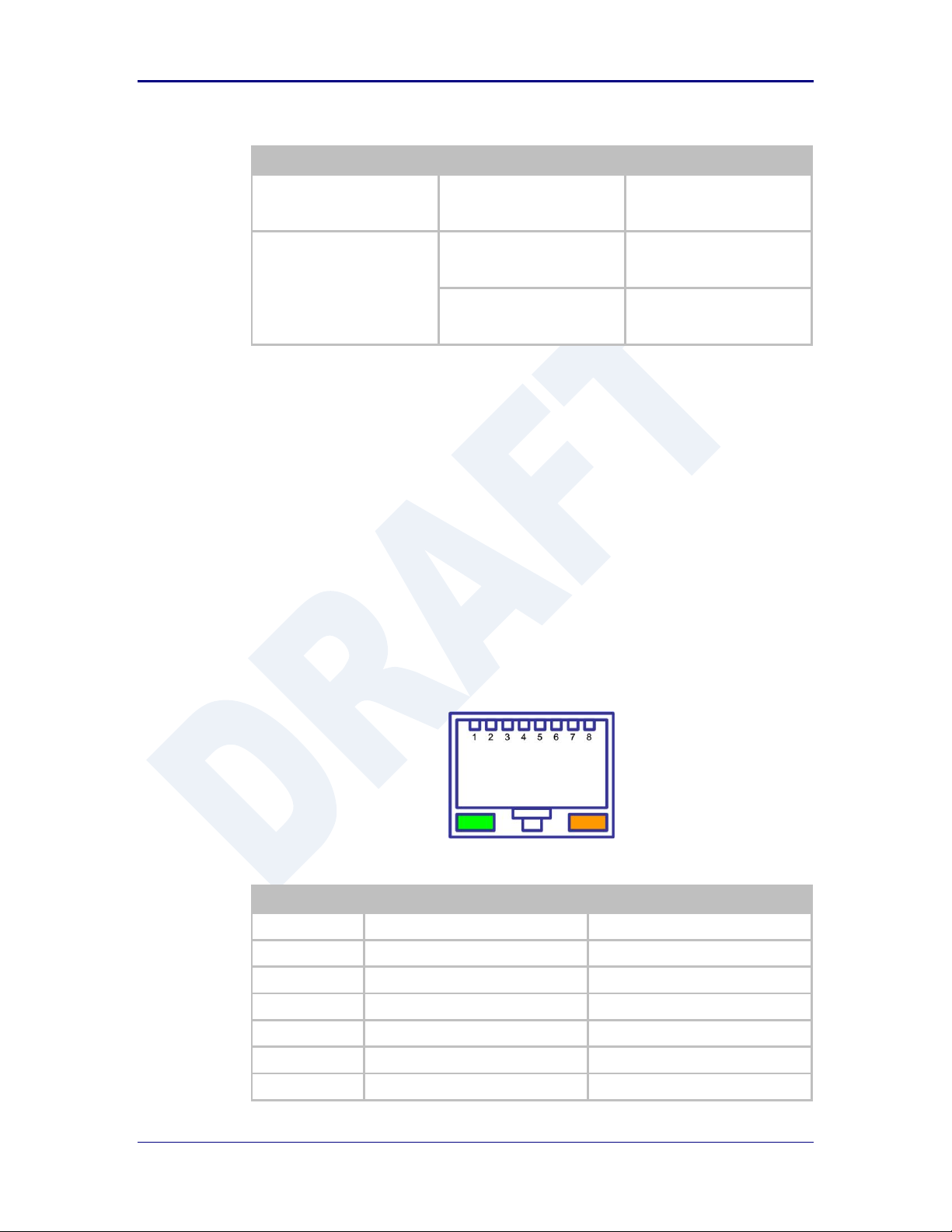
Pin
RJ45 Socket (Industrial)
RJ45 Plug (Enterprise)
1
TxD+
RxD+
2
TxD-
RxD-
3
RxD+
TxD+ 4 NC
NC 5 NC
NC 6 RxD-
TxD- 7 NC
NC
Table 2 - Serial Ports by Product Class
The Port 1 and Port 2 interfaces support the following configurations:
BAUD: 300, 600, 1200, 2400, 4800, 9600, 14400, 19200, 28800, 38400,
57600, 115200, 230400, 460800, 921600
Flow Control: None, Hardware (CTS/RTS), Software (XON/XOFF)
Port 1 Default settings: 9600, 8, N, 1, No Flow Control.
Port 2 Default settings: 9600, 8, N, 1, No Flow Control.
6.2 Ethernet Port
The AirborneDirect™ Ethernet devices support a single interface. This is a
10/100Mbps interface that supports auto negotiation and cross-over cabling. The
interface also supports both half and full duplex for 10Mbps and 100Mbps. Table
XX shows the interface pin out.
Figure 7 - Ethernet Jack Pin Out
Table 3 - Ethernet Connector Pin Out
100-8510-110 2/21/2011 19
Page 20
Quatech, Inc. AirborneDirect™ User Manual
Pin
RJ45 Socket (Industrial)
RJ45 Plug (Enterprise)
8
NC
NC
Green LED
Valid TCP/IP connection made with
Airborne Adapter:
Off No TCP/IP connection
On Valid TCP/IP Connection
N/A
Yellow LED
Power-on Self Test (POST):
Off Not powered or has failed POST
On Passed POST
N/A
Type
Description
Product Class
Serial
DE-9 Connector Male
Enterprise, Industrial
Ethernet
RJ45 Plug
Enterprise
Ethernet
RJ45 Socket
Industrial
Antenna
RP-SMA
Enterprise, Industrial
Power
2.1mm Barrel Jack
Enterprise, Industrial
Power
2 Position Terminal Block
Industrial
6.3 Connector Definition
There are a total of five connectors used by the AirborneDirect™ family. Which
connectors are available on your product depend upon the model you purchased.
The definition for the connectors is common to all product classes. Table 4
provides definitions for the connectors.
Table 4 - Connector Description
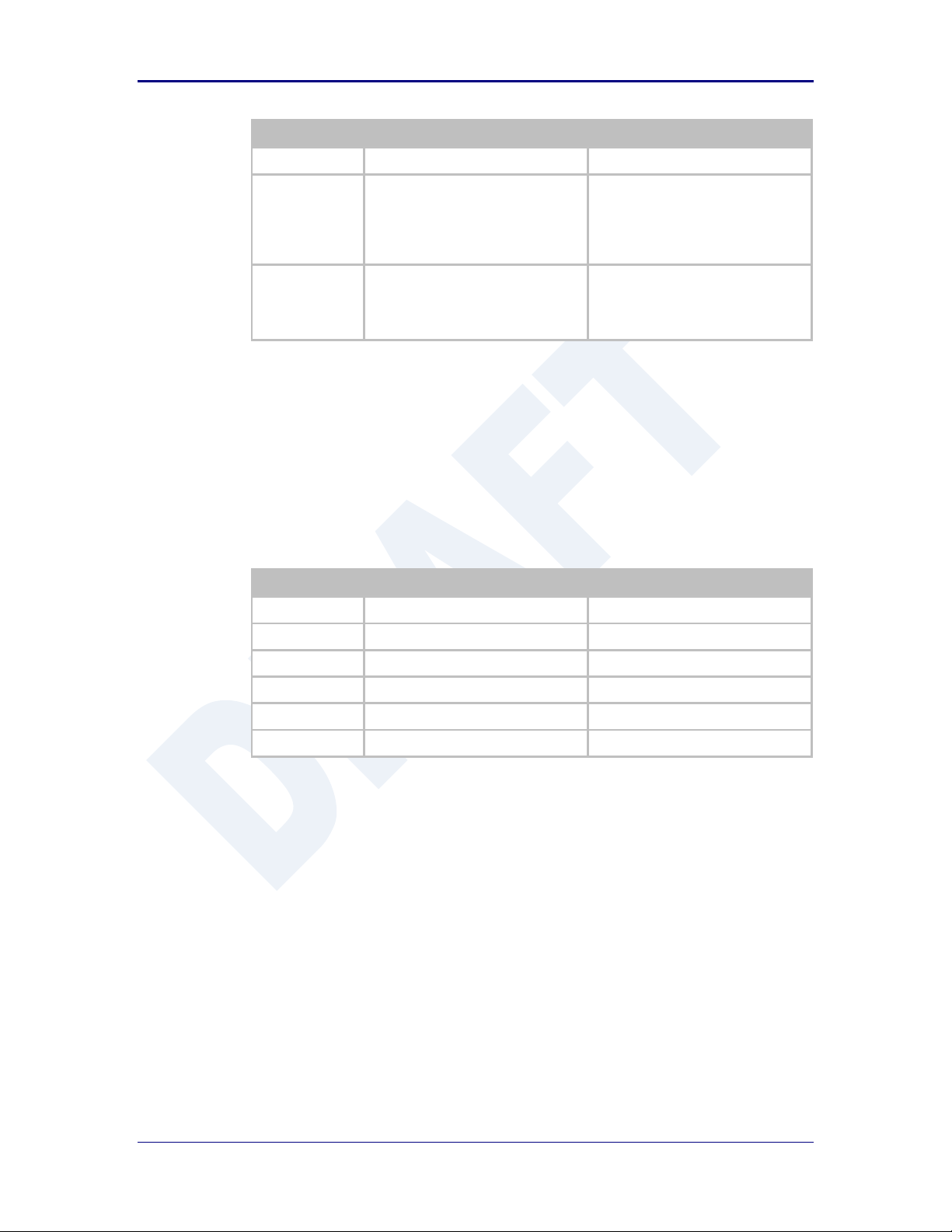
6.4 OEM Reset Switch (Factory Reset)
All AirborneDirect™ devices support the ability to reset the configuration back to
OEM defaults. This is useful when a device has been incorrectly configured and
has lost the ability to communicate on any of the available ports, preventing
access to one of the configuration interfaces and blocking your ability to recover
the device by correcting the configuration.
The following Table 5 describes the sequence for OEM resetting the
AirborneDirect™ devices. All devices use the same process however the
loo0cation of the OEM reset switch varies between the product families.
20 2/21/2011 100-8510-110
Page 21
AirborneDirect™ Users Guide Quatech, Inc.
1
Disconnect or turn off the power supply.
2
Press the OEM reset (factory reset) button.
This may require the use of a small narrow object, it is important that this object is
not sharp as it may cause damage to the unit.
3
While holding the OEM button pressed reapply power to the unit.
4
Hold the OEM reset button for 5-6 seconds after power has been applied.
5
Release the OEM reset button.
6
The device will restart with the installed OEM defaults. If no OEM Configuration is
applied the device will return to Quatech factory defaults.
See section 15.6 on use of OEM factory configurations.
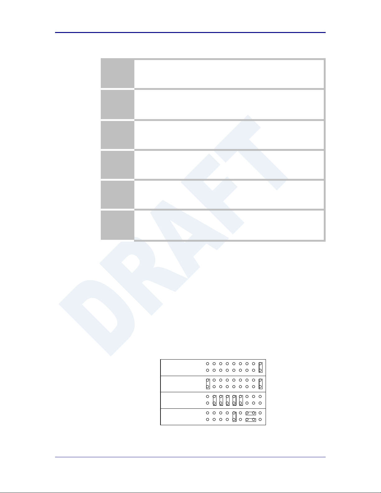
RS-485 w/
Termination
RS-232 Power Pin 9,
Cable Sense
1
1
RS-232
Cable Sense
1
RS-422 w/
Termination
1
Table 5 - OEM Reset Procedure
The location of the OEM reset button for the Enterprise devices is on the back of
the enclosure, underneath the label near the pigtail. The Industrial devices OEM
reset button is on the Ethernet/Power end of the box next to the 2.1mm barrel
connector (See section 10.0)
6.5 Enterprise Serial Interface Jumpers
The Enterprise Serial device server supports RS232/422/485 interface drivers, as
well as power over pin 9. Selection of these options is made through both the
web interface and hardware jumpers. Figure 8shows the interface selection
jumpers for the different interface types.
Figure 8- Interface Selection Jumpers
The jumper selections must be made while the device is unpowered and before
being used in the final application.
100-8510-110 2/21/2011 21
Page 22
Quatech, Inc. AirborneDirect™ User Manual
The interface type selected by the interface jumpers in Figure 8 must match the
selected configuration for the Configuration | Serial Port Settings | Serial
Interface Type setting in the web interface.
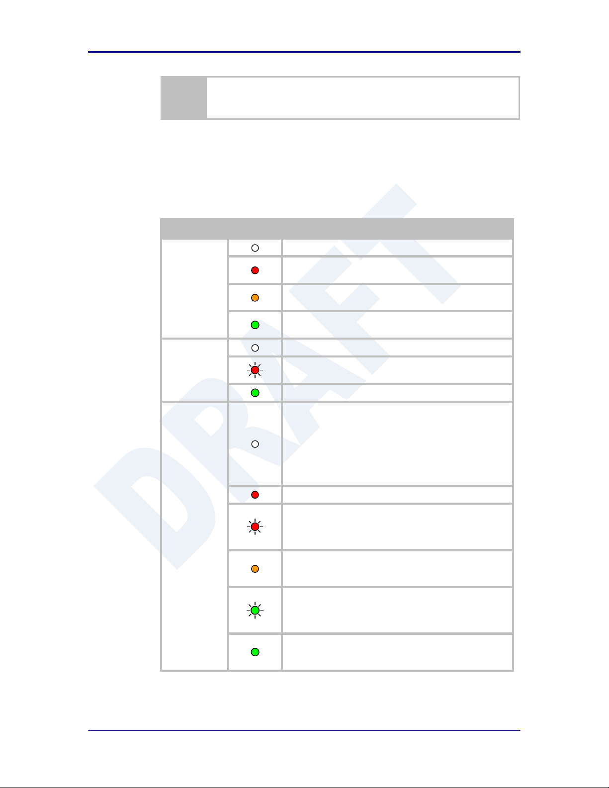
LED
Color
Airborne Device State
POWER
Adapter is not powered.
Adapter failed Power On Self Test (POST) and is not
configured for wireless communication.
Adapter passed POST but is not configured for wireless
network communication.
Adapter passed post and is configured for wireless
communication.
LINK
Adapter is not powered.
(Periodic Blinking) Adapter is searching for a valid network
(Access Point) that matches device’s configuration.
Adapter has successfully associated with an Access Point.
COMM
If Power LED is also Off then Adapter is not powered.
If Power LED is On then either:
A physical connection detected on Serial/Ethernet
cable.
No TCP session from wireless interface has been
established.
No physical Serial/Ethernet connection has been detected.
(Blinking – OFF/Red) A physical Serial/Ethernet connection
has been detected and there is traffic across the interface. No
TCP connection to the adapter has been established on the
wireless interface.
A TCP connection to the adapter from the wireless interface
has been established but no physical connection on the
Serial/Ethernet interface has been detected.
(Blinking – Green/Orange) A physical Serial/Ethernet
connection has been detected and there is Serial/Ethernet
traffic across the interface. A TCP connection to the adapter
has been established (On WLAN or Ethernet interface).
A physical Serial/Ethernet connection has been detected. A
TCP connection to the adapter has been established from the
WLAN or Ethernet interface but no traffic has been detected.
6.6 Indicator LED’s
The devices provide indicator LED’s to provide feedback on the state of the
device. These are a useful tool during installation and troubleshooting.
Table 6 - Enterprise LED Indicators
22 2/21/2011 100-8510-110
Page 23
AirborneDirect™ Users Guide Quatech, Inc.
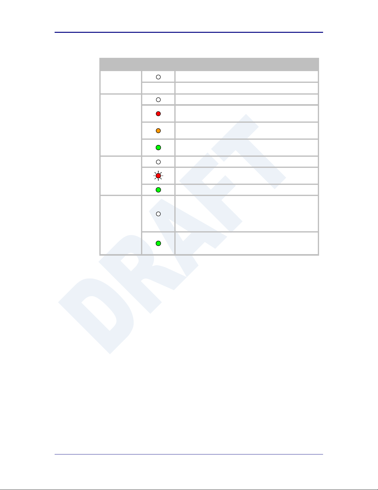
LED
Color
Airborne Device State
POWER
Adapter is not powered.
Adapter is powered.
POST
Adapter is not powered.
Adapter failed Power On Self Test (POST) and is not
configured for wireless communication.
Adapter passed POST but is not configured for wireless
network communication.
Adapter passed post and is configured for wireless
communication.
LINK
Adapter is not powered.
(Periodic Blinking) Adapter is searching for a valid network
(Access Point) that matches device’s configuration.
Adapter has successfully associated with an Access Point.
COMM
If Power LED is also Off then Adapter is not powered.
If Power LED is On then:
No TCP session from WLAN or Ethernet interface has
been established.
A TCP connection to the adapter has been established from
the Wireless or Ethernet interfaces but no traffic has been
detected.
Table 7 - Industrial LED Indicators
100-8510-110 2/21/2011 23
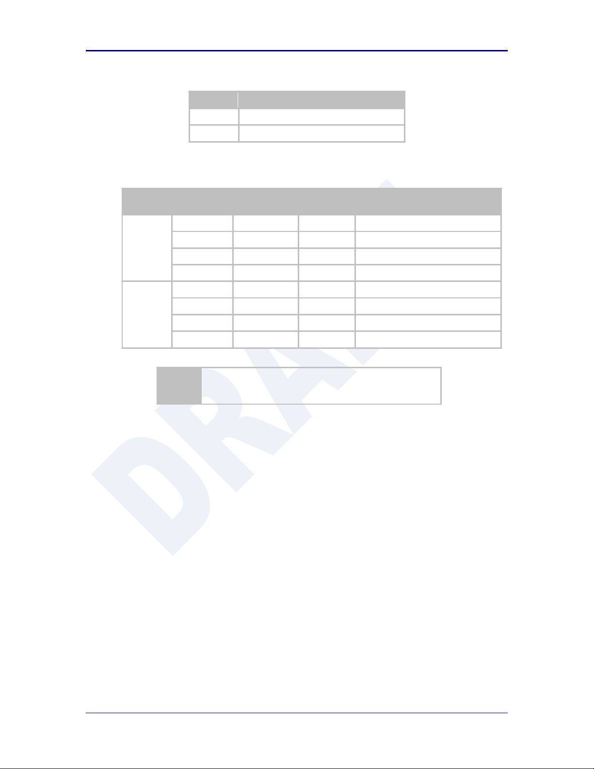
Page 24

Quatech, Inc. AirborneDirect™ User Manual
Parameter
Min
Max
Unit
Maximum Supply Voltage - Enterprise
4.5
5.5
VDC
Maximum Supply Voltage - Industrial
5.0
36
VDC
Power Dissipation
3.00
W
Operating Temperature Range
-40
85 oC
Storage Temperature
-50
125 oC
Symbol
Parameter
Rate (Mb/s)
Min
Average
dBm / mW
Peak
dBm / mW
Units
P
OUTB
Transmit Power
Output 802.11b
11, 5.5, 2, 1
13.0
15.0
31.6
dBm
P
OUTG
Transmit Power
Output 802.11g
6, 9, 12, 18, 24,
36, 48, 54
13.0
15.0
31.6
dBm
P
RSENB
Receive
Sensitivity
802.11b
11 -89
dBm
1 -93
P
RSENG
Receive
Sensitivity
802.11g
54 -72
dBm
36 -79 18 -85 6 -90
F
RANGEBG
Frequency
Range
2412 2484
MHz
The transmit power is automatically controlled by the device for minimum power
consumption.
The transmit power at the antenna connector is 15dBm±2dBm.
7.0 Electrical & RF Specification
Table 8- Absolute Maximum Values1
Note: 1. Values are absolute ratings, exceeding these values may cause permanent damage to the device.
Table 9 - RF Characteristics – 802.11b/g
24 2/21/2011 100-8510-110
Page 25
AirborneDirect™ Users Guide Quatech, Inc.
Band
Supported Data Rates (Mb/s)
802.11b
11, 5.5, 2, 1
802.11g
54, 48, 36, 24, 18, 12, 9, 6
Band
Region
Freq Range
(GHz)
No. of
Channels
Channels
802.11b
US/Canada
2.401 - 2.473
11
1 – 11
Europe
2.401 - 2.483
13
1 – 13
France
2.401 - 2.483
13
1 – 13
Japan
2.401 - 2.495
14
1 – 14
802.11g
US/Canada
2.401 - 2.473
11
1 – 11
Europe
2.401 - 2.483
13
1 – 13
France
2.446 - 2.483
13
1 – 13
Japan
2.401 - 2.483
13
1 – 13
1. Only channels 1, 6 and 11 are non-overlapping.
Table 10 - Supported Data Rates by Band
Table 11 - Operating Channels
100-8510-110 2/21/2011 25
Page 26

Quatech, Inc. AirborneDirect™ User Manual
Data Rate
Typical Outdoor Distance
(Unity gain antenna)
Typical Outdoor Distance
(2dBi antenna gain on each end for
B/G mode)
1.0 Mb/s
240m
380m
11.0 Mb/s
135m
215m
6Mb/s 802.11g
135m
215m
6Mb/s 802.11a
49m
155m
54Mb/s 802.11g
12m
19m
54Mb/s 802.11a
4.5m
14m
7.1 AC Electrical Characteristics – Transmitter
Transmit power is automatically managed by the device for minimum power
consumption. The transmit power at the RF connector is +15dBm 2 dBm for
802.11b/g Modes (all rates).
7.2 Performance/Range
The following table illustrates the typical data rates, performance and range the
device is capable of providing using an omni-directional antenna.
Table 12 - Radio Typical Performance Range
Ranges are affected by receiver sensitivity; transmit power, free-space path loss,
antenna gain, and link margin. Actual range will vary from those stated. Non-lineof-site applications will result in typical values less than shown above.
The Data Rate is the supported connection rate for the wireless link, the actual
data throughput for the link will be less than the stated data rates.
26 2/21/2011 100-8510-110
Page 27

AirborneDirect™ Users Guide Quatech, Inc.
8.0 Antenna
The unit supports antenna connection through a single Hirose U.FL connector, located on
the top surface of the radio next to the RF shielding.
Any antenna used with the system must be designed for operation within the 2.4GHz
ISM band and specifically must support the 2.412GHz to 2.482GHz for 802.11b/g
operation. They are required to have a VSWR of 2:1 maximum referenced to a 50
system impedance.
8.1 Antenna Selection
The Airborne radio supports a number of antenna options, all of which require
connection to the U.FL connectors on the radio. Ultimately the antenna option
selected will be determined by a number of factors, including consideration of the
application, mechanical construction and desired performance. Since the number
of possible combinations is endless we will review some of the more common
solutions in this section. If your application is not covered during this discussion
please contact Technical Support for more specific answers.
The available antenna connections include:
Host board mounted antenna
Host Chassis mounted antenna
Embedded antenna
In addition to the above options, location and performance need to be
considered. The following sections discuss these items.
8.2 Host Board Mounted Antenna
Host board mounted requires that an antenna connection is physically mounted
to the host system board. It also requires that the host board include a U.FL
connector (two (2) if diversity is being used) to allow a U.FL to U.FL coaxial lead
to connect from the radio to the host board. It will then require 50 matched PCB
traces to be routed from the U.FL connector to the antenna mount.
There are several sources for the U.FL to U.FL coaxial cable these include
Hirose, Sunridge and IPEX. Please contact Quatech for further part numbers and
supply assistance.
This approach can simplify assembly but does require that the host system
configuration can accommodate an antenna location that is determined by the
host PCB. There are also limitations on the ability to seal the enclosure when
using this approach.
This approach also restricts the selection of available antenna. When using this
approach, antennas that screw or press fit to the PCB mount connector must be
used. There are many options for the antenna connector type, however if you
100-8510-110 2/21/2011 27
Page 28

Quatech, Inc. AirborneDirect™ User Manual
Antenna Type
Features
Cost
Size
Availability
Performance
PCB Embedded
Lowest
Largest
Custom
Poor
Chip
Low
Small
Standard
Poor
Flying Lead
Low
Small
Standard
Fair
wish to utilize the FCC/IC modular approval the connector choice must comply
with FCC regulations. These state that a non-standard connector, e.g. RPTNC/RP-SMA, is required. TNC/SMA connectors are not allowed.
8.3 Host Chassis Mounted Antenna
Host Chassis mounted antennas require no work on the host PCB. They utilize
an antenna type called ‘flying lead’. There are two types of flying leads; one
which provides a bulkhead mounted antenna connector and one which provides
a bulk head mounted antenna. The type you choose will be determined by the
application.
A flying lead system connects a U.FL coaxial lead to the radio’s U.FL connector.
The other end of the coax is attached to either a bulkhead mounted antenna
connector or directly to an antenna that has an integrated bulkhead mount.
In either of the two cases, the use of this approach significantly reduces the
antenna system development effort and provides for greater flexibility in the
available antenna types and placement in the host system chassis.
When using the flying lead antenna (integrated bulk head mounting), there are no
connector choice restrictions for use with the FCC/IC modular certification.
However if the flying lead connector is used, the same restrictions as identified
for the Host Mounted Antenna apply.
There are many suppliers of flying lead antenna and connectors. Quatech’s
Airborne Antenna product line offers a range of antenna solutions.
8.4 Embedded Antenna
Use of Embedded antenna can be the most interesting approach for M2M,
industrial and medical applications. Their small form factor and absence of any
external mounting provides a very compelling argument for their use. There is a
downside to this antenna type and it comes with performance. Antenna
performance for all of the embedded options will, in most cases, be less that that
achievable with external antenna. This does not make them unusable; it will
impact choice of antenna type and requires more focus on placement.
The three main embedded antenna types are PCB embedded, chip (PCB
mounted) and flying lead; each has its advantages and disadvantages (See
Table 13).
Table 13 - Embedded Antenna Options
28 2/21/2011 100-8510-110
Page 29

AirborneDirect™ Users Guide Quatech, Inc.
PCB Embedded – This approach embeds an antenna design into the host PCB.
This approach is very common with add-in WiFi cards (CF, PCMCIA, SDIO, etc.)
as it requires no external connections and is the cheapest production approach.
The lower production cost requires significant development cost and lack of
performance and flexibility.
Chip – The integration of a chip antenna is simple and requires a relatively small
footprint on the host system, however, it does suffer from the same limitations of
flexibility and performance seen with the PCB embedded approach. There are
relatively large numbers of suppliers of this type of antenna; there is also a range
of configuration and performance options.
Flying Lead – This approach is similar to the flying lead solution for external
antennas. The difference is that the form factors are smaller and provide a range
of chassis and board mounting options, all for internal use. This approach suffers
less from the performance and flexibility limitations of the other approaches,
since the location of the antenna it not determined by the host PCB design. The
assembly of a system using this approach maybe slightly more complex since
the antenna is not necessarily mounted on the host PCBA.
8.5 Antenna Location
The importance of this design choice cannot be over stressed. It can in fact be
the determining factor between success and failure of the WiFi implementation.
There are several factors that need to be considered when determining location:
Distance of Antenna from radio
Location of host system
Proximity to RF blocking or absorbing materials
Proximity to potential noise or interference
Position relative to infrastructure (Access Points or Laptops)
Orientation of host system relative to infrastructure
Is it known
Is it static
To minimize the impact of the factors above the following things need to be
considered during the development process:
Minimize the distance between the radio and the location of the antenna. The
coaxial cable between the two impacts the Transmit Power and Receive
Sensitivity negatively. Quatech recommends using 1.32-1.37mm outer
diameter U.FL coaxial cables.
Minimize the locations where metal surfaces come into contact or are close
to the location of the antenna.
Avoid locations where RF noise, close to or over lapping the ISM bands, may
occur. This would include microwave ovens and wireless telephone systems
in the 2.4GHz and 5.0GHz frequency range.
Mount the antenna as high on the equipment as possible.
100-8510-110 2/21/2011 29
Page 30

Quatech, Inc. AirborneDirect™ User Manual
Locate the antenna where there is a minimum of obstruction between the
antenna and the location of the Access Points. Typically Access Points are
located in the ceiling or high on walls.
Keep the main antenna’s polarization vertical, or in-line with the antenna of
the Access Points. 802.11 systems utilize vertical polarization and aligning
both transmit and receive antenna maximizes the link quality.
Even addressing all of the above factors does not guarantee a perfect
connection, however with experimentation an understanding of the best
combination will allow a preferred combination to be identified.
8.6 Performance
Performance is difficult to define as the appropriate metric changes with each
application or may indeed be a combination of parameters and application
requirements. The underlying characteristic that, in most cases, needs to be
observed is the link quality. This can be defined as the bandwidth available over
which communication between the two devices can be performed. The lower the
link quality the less likely the devices can communicate.
Measurement of link quality can be made in several ways: Bit Error Rate (BER),
Signal to Noise (SNR) ratio, Signal Strength, and may also include the addition of
distortion. The link quality is used by the radio to determine the link rate.
Generally as the link quality for a given link rate drops below a predefined limit,
the radio will drop to the next lowest link rate and try to communicate using it.
The reciprocal is also true. If the radio observes good link quality at one rate it
will try to move up to the next rate to see if communication can be sustained
using it. It is important to note that for a given position the link quality improves as
the link rate is reduced. This is because as the link rate drops the radios Transmit
power and Receive sensitivity improve.
From this it can be seen that looking at the link rate is an indirect way of
assessing the quality of the link between the device and an Access Point. You
should strive to make the communication quality as good as possible in order to
support the best link rate. However be careful not to over specify the link rate.
Consider your application’s bandwidth requirements and tailor your link rate to
optimize the link quality. For example, the link quality for a location at 6Mb/s is
better than it would be for 54Mb/s. If the application only needs 2Mb/s of data
throughput, the 6Mb/s rate would provide a better link quality.
Aside from the radio performance, there are a number of other things that
contribute to the link quality. These include the items discussed earlier and
choices made when looking at the overall antenna gain. The antenna gain
contributes to the Equivalent Isotropically Radiated Power (EIRP) of the system.
This is part of an overall measurement of the link quality called link margin.
30 2/21/2011 100-8510-110
Page 31

AirborneDirect™ Users Guide Quatech, Inc.
Link Margin provides a measure of all the parts of the RF path that impact the
ability of two systems to communicate. The basic equation looks like this:
EIRP (dB) = TxP + TxA – TxC
Link Margin (dB) = EIRP – FPL + (RxS + RxA – RxC)
Where: TxP = Transmitter output power (dBm)
TxA = Transmitter antenna gain (dBi)
TxC = Transmitter to Antenna coax cable loss (dB)
FPL = Free Path Loss (dB)
RxS = Receiver receive sensitivity (dBm)
RxA = Receiver antenna gain (dBi)
RxC = Receiver to Antenna coax cable loss (dB)
This is a complex subject and requires more information than is presented here,
Quatech recommends at reviewing the subject and evaluating any system at a
basic level.
It is then possible, with a combination of the above items and an understanding
of the application demands, to achieve a link quality optimized for the application
and host design. It is important to note that this is established with a combination
of hardware selection, design choices and configuration of the radio.
100-8510-110 2/21/2011 31
Page 32

Quatech, Inc. AirborneDirect™ User Manual
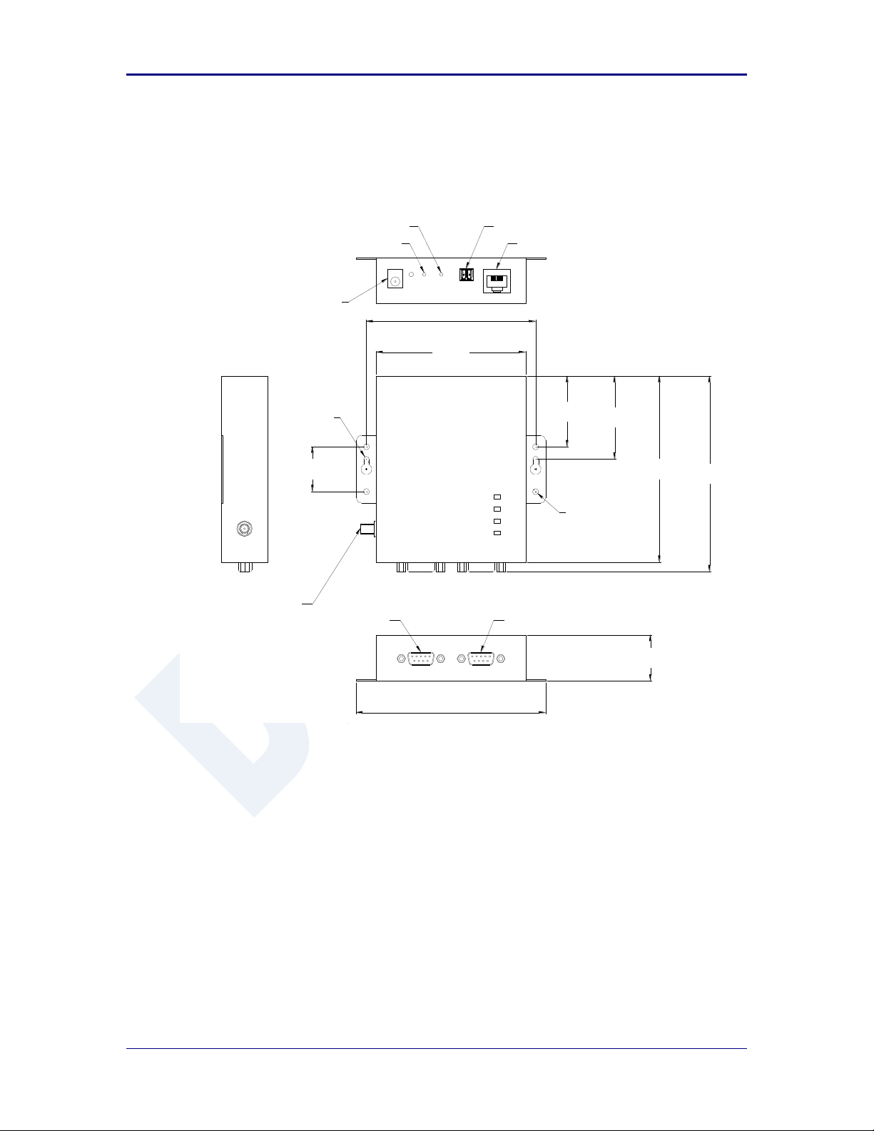
9.0 Mechanical Outline – Enterprise Class
Antenna Connector: RP-SMA (Reverse Polarity – SMA)
Requires 2.4GHz ISM band antenna, 50 input impedance, RP-SMA connector
Serial Connector: DB-9M (Male)
Requires DB-9 (Female)
Ethernet Connector: RJ-45 Plug
Requires RJ-45 socket, 10/100 Ethernet interface
Power Connector: 2.1mm Barrel Jack
Requires 2.1mm ID, 5.5mm OD, +5VDC center pin.
32 2/21/2011 100-8510-110
Page 33
AirborneDirect™ Users Guide Quatech, Inc.
Terminal Block (Power)
10/100 Ethernet Socket
System Reset
Factory Reset
2.1mm Barrel Jack
Serial Port 1
Serial Port 2
RP-SMA Antenna Connector
Ø3.56mm
[Ø0.14"]
Ø3.81mm
[Ø0.15"]
107.42mm
[4.23"]
28.44mm
[1.12"]
52.72mm
[2.08"]
44.85mm
[1.77"]
118.14mm
[4.65"]
120.12mm
[4.73"]
29.21mm
[1.15"]
124.14mm
[4.89"]
94.72mm
[3.73"]
CONNECT
LINK
POST
POWER
10.0 Mechanical Outline – Industrial Class
Antenna Connector: RP-SMA (Reverse Polarity – SMA)
Requires 2.4GHz ISM band antenna, 50 input impedance, RP-SMA connector
Serial Connector: DB-9M (Male)
Requires DB-9F (Female)
Ethernet Connector: RJ-45 Socket
Power Connector: 2.1mm Barrel Jack
Requires RJ-45 plug, 10/100 Ethernet interface
Requires 2.1mm ID, 5.5mm OD, +5VDC center pin.
Power Connector: Terminal Block (2 connector)
Requires 16-30 AWG gauge wire.
100-8510-110 2/21/2011 33
Page 34

Quatech, Inc. AirborneDirect™ User Manual
11.0 Getting Started
11.1 Unpack the AirborneDirect™ Device
Unpack the AirborneDirect™ Device and compare the package contents with the
items listed on the front of the included Quick Start Guide. If any item is missing
or damaged, contact Quatech immediately.
Contact details can be found at www.quatech.com/support.
11.2 Connect AirborneDirect™ to host
Connect the Airborne Direct unit to a system capable of configuring it. The
preferred initial connection depends upon the class and type of product:
Serial – Enterprise: Connect to a serial port on the host or through a serial to
USB adapter.
Serial – Industrial: Connect the RJ-45 socket to a RJ-45 socket using a
CAT 5 Ethernet cable.
Ethernet – Enterprise: Connect to an RJ-45 socket on the host.
Ethernet – Industrial: Connect the RJ-45 socket to a RJ-45 socket using a
CAT 5 Ethernet cable.
11.3 Attach Antenna and Power-up the AirborneDirect™
Attach the supplied antenna to the RP-SMA connector on the AirborneDirect™
unit. Connect the supplied AC adapter to the power connector. If using your own
power supply make sure the correct power connector type and polarity are being
used, verify the appropriate voltage to be applied by checking Error! Reference
source not found. for the correct product class. Confirm that the device is
receiving power by verifying that the POST LED is lit when the supply is applied.
34 2/21/2011 100-8510-110
Page 35

AirborneDirect™ Users Guide Quatech, Inc.
1
Open the AirborneDirect™ packaging and locate the Install CD.
2
Place the CD in the CD/DVD drive of the laptop or desktop you will be using to configure the
AirborneDirect™ device. Follow the on screen directions for installation of the appropriate device
software and documentation.
3
Connect the Ethernet cable on ABDG to an Ethernet port on the laptop or desktop system.
4
Apply power to the ABDG-SE-IN5XXX.
5
The unit will boot and display one of the following LED patterns:
ABDG-SE-IN5XXX
COMM: Off
LINK : Off
POST: Orange
POWER: Blue
6
Run the Airborne Management System application. This was installed during the CD installation and a
menu item will be found in the Airborne folder located in the programs directory of your system.
When the application opens the following dialog will be displayed:
Select Group Name: manuf and enter Group Password: dpac
12.0 Configuring Device – Industrial Serial (ABDG-SE-IN5XXX)
The following describes initial connection to an AirborneDirect™ Serial Device Server
(ABDG-SE-IN5XXX). If you have an Ethernet device (ABGD-ET-DP5XX/IN5010), please
go to section 14.0. If you have purchased a SE-DP5XX device please go to section 13.0
for the set-up instructions.
The instructions in Table 14 provide step-by-step instructions for configuration of the
ABDG-SE-IN5XXX product family.
Table 14 - SE-IN5XXX Accessing the Web Interface
100-8510-110 2/21/2011 35
Page 36

Quatech, Inc. AirborneDirect™ User Manual
7
The AMC will load and discover the attached device.
8
Right Click the Unmanaged Device then:
1. Select Change Management State
2. Select Manage OEM-Cfg1
3. Select Device OEM-Cfg1 is Factory Default
9
The devices status will move to managed and the device will be displayed under the device type/group it
belongs too. Right click the device and then:
1. Select Connectivity Tools
2. Select Launch Web Browser for OEM-Cfg1
10
Opening web page shows adapter status.
Links to the available configuration options are identified in the left hand menu. The top menu bar
provides access to different operations that can be performed by the AirborneDirect™ device. See
section 15.0 for a full description of how to use the web interface.
11
Using Express Setup:
If this is the first time you have configured the device the Express Setup page will be displayed, please
refer to section 16.0 to continue set-up of the device.
If this is not the first time please move to section to update the configuration
36 2/21/2011 100-8510-110
Page 37

AirborneDirect™ Users Guide Quatech, Inc.
12
When the Reboot button is pressed the unit will restart and install new settings. This may take 15-20
seconds. Please refresh the web interface after the boot cycle has completed.
13
When configured correctly the LED pattern should match the following:
ABDG-SE-IN5XXX No TCP Connection TCP Connection
COMM: Off Green
LINK : Green Green
POST: Green Green
POWER: Blue Blue
14
To use the adapter on the wireless network, address all traffic to the IP address of the wireless interface
of the ABDG-SE- IN5XXX. This address is listed in the home page of the web interface.
100-8510-110 2/21/2011 37
Page 38

Quatech, Inc. AirborneDirect™ User Manual
It may be necessary to use a gender changed that includes a Null Modem adapter.
CLI Command
Description
Send Break Sequence
The serial port starts up in a listen mode waiting for a
request for a data tunnel. To access the CLI mode in
which set-up can take place the break sequence must be
sent.
The default break sequence for the device is ÿ~ABD
The sequence must be sent with no trailing characters.
If received correctly the device will respond OK.
auth dpac dpac <CR>
The module responds with OK, indicating that it
executed the command successfully. (If you did not
receive OK, check the settings in your terminal emulation
program).
You will have to break into CLI mode and log into the module after any reset or
restart.
13.0 Configuring Device – Enterprise Serial (ABDG-SE-DP5XX)
The ABDG-SE-DP5XX family does not have an Ethernet port for initial configuration so
initial configuration can be performed through the serial port. To do this it is necessary to
connect using the serial connector.
13.1 Connect a Host Computer
Connect the serial pigtail connector to the serial port on a host computer.
13.2 Interacting with the AirborneDirect™ device
On the Host computer, use a terminal emulation program to interact with the
device issuing Quatech Command Line Interface (CLI) commands. CLI
commands let you request status or change parameter settings. Press the Enter
key (<CR>) after each command line you type. After the module starts, type the
following CLI command to log in (you must log in before CLI commands can be
recognized):
Table 15 - UART Authentication
38 2/21/2011 100-8510-110
Page 39

AirborneDirect™ Users Guide Quatech, Inc.
CLI Command
Description
wl-scan<CR>
The module scans for APs and returns information on
each one it discovers. Note the SSID value that is
returned, as you will need to enter it when configuring
the device in the next steps.
wl-ssid [SSID]<CR>
Associates the module with the network name [SSID]
you specify. [SSID] is the value returned by the wlscan command.
commit<CR>
Stores the information to flash memory.
restart
Restarts the device and installs the new settings.
CLI Command
Description
Send Break Sequence
The serial port starts up in a listen mode waiting for a
request for a data tunnel. To access the CLI mode in
which set-up can take place the break sequence must
be sent.
The default break sequence for the device is ÿ~ABD
The sequence must be sent with no trailing characters.
If received correctly the device will respond OK.
auth dpac dpac <CR>
Authenticate with the device server.
wl-ip<CR>
The module returns the IP address assigned to it by
the DHCP server.
13.3 Determine and Store the Access Point SSID
On the Host computer, use the terminal emulation program to type the following
CLI commands in the order shown:
Table 16 - UART SSID & Authentication
If your access point has security enabled, you will also need to use the CLI to
enter those parameters (See the Enterprise CLI Reference Guide for details).
That setup is outside the scope of this user guide, which assumes that the AP
being tested with has no security.
After issuing the commands, the unit will restart and apply the network settings.
Once restarted the LINK LED will stop blinking and go solid. If DHCP is enabled
on the network the POWER and LINK LED’s will turn solid green.
13.4 Determine the Device’s IP address
On the Host computer, use the terminal emulation program to type the following
CLI commands:
Table 17 - UART Determine Module's IP Address
100-8510-110 2/21/2011 39
Page 40

Quatech, Inc. AirborneDirect™ User Manual
The above process can be achieved by any of the available Terminal Emulation
programs. Please follow the specific applications requirements to make the TCP/IP
connection and authenticate with the module.
13.5 Accessing the Device Using the Web Interface
See section 15.0.
13.6 Accessing the Device Using Telnet
On the Remote computer, use a terminal emulation program to start a Telnet
session. To connect to the device using TCP/IP, use the IP address obtained in
section 13.4 to connect on port 23.
The terminal emulator will attempt to connect to the IP address; if successful you
will now be able to use the WLAN interface for configuration of the device
through either CLI or web.
For more information on the full CLI command set please refer to the Airborne
Enterprise Command Line Reference Manual.
40 2/21/2011 100-8510-110
Page 41
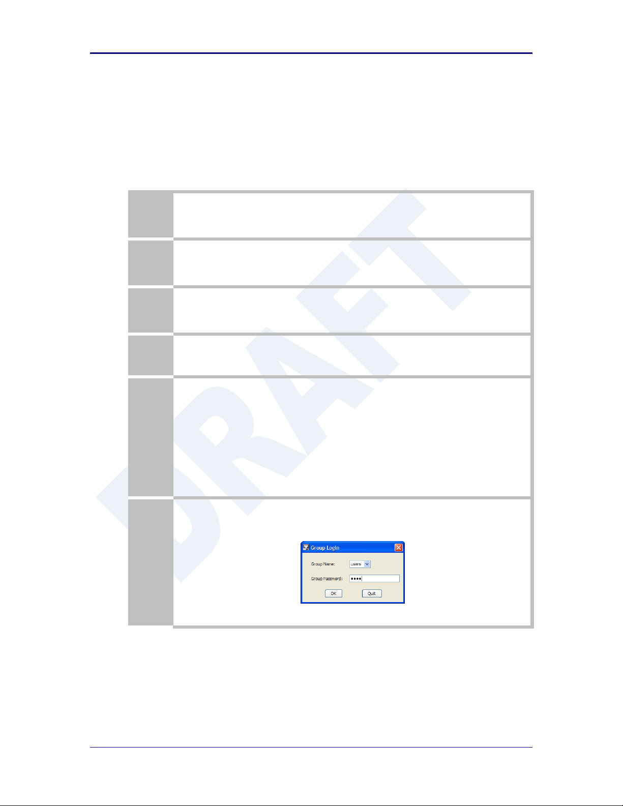
AirborneDirect™ Users Guide Quatech, Inc.
1
Open the AirborneDirect™ packaging and locate the Install CD.
2
Place the CD in the CD/DVD drive of the laptop or desktop you will be using to configure the
AirborneDirect™ device. Follow the on screen directions for installation of the appropriate device
software and documentation.
3
Connect the Ethernet cable on ABDG to an Ethernet port on the laptop or desktop system.
4
Apply power to the ABDG-ET-DP5XX/IN5XXX.
5
The unit will boot and display one of the following LED patterns:
ABDG-ET-DP5XX Associated (Open Network) Not Associated
POWER: Green Green
LINK : Green Red (Periodic Blinking)
COMM: Red Red
ABDG-ET-IN5XXX
COMM: Off
LINK : Off
POST: Orange
POWER: Blue
6
Run the Airborne Management System application. This was installed during the CD installation and a
menu item will be found in the Airborne folder located in the programs directory of your system.
When the application opens the following dialog will be displayed:
Select Group Name: manuf and enter Group Password: dpac
14.0 Configuring Device – Enterprise/Industrial Ethernet
The following instructions describe how access the AirborneDirect™ Ethernet device and
web interface for initial configuration of the unit.
Table 18 - ET-DP5XX/IN5XXX Accessing the Web Interface
100-8510-110 2/21/2011 41
Page 42

Quatech, Inc. AirborneDirect™ User Manual
7
The AMC will load and discover the attached device.
8
Right Click the Unmanaged Device then:
4. Select Change Management State
5. Select Manage OEM-Cfg1
6. Select Device OEM-Cfg1 is Factory Default
9
The devices status will move to managed and the device will be displayed under the device type/group it
belongs too. Right click the device and then:
3. Select Connectivity Tools
4. Select Launch Web Browser for OEM-Cfg1
10
Opening web page shows adapter status.
Links to the available configuration options are identified in the left hand menu. The top menu bar
provides access to different operations that can be performed by the AirborneDirect™ device. See
section 15.0 for a full description of how to use the web interface.
11
Using Express Setup:
If this is the first time you have configured the device the Express Setup page will be displayed, please
refer to section 16.0 to continue set-up of the device.
If this is not the first time please move to section to update the configuration
42 2/21/2011 100-8510-110
Page 43

AirborneDirect™ Users Guide Quatech, Inc.
12
When the Reboot button is pressed the unit will restart and install new settings. This may take 15-20
seconds. Please refresh the web interface after the boot cycle has completed.
13
When configured correctly the LED pattern should match the following:
ABDG-ET-DP5XX
POWER: Green
LINK : Green
COMM: Red
ABDG-ET-IN5XXX No TCP Connection TCP Connection
COMM: Off Green
LINK : Green Green
POST: Green Green
POWER: Blue Blue
14
To use the adapter on the wireless network, address all traffic to the IP address of the wireless interface
of the ABDG-ET- DP5XX/IN5XXX. This address is listed in the home page of the web interface.
100-8510-110 2/21/2011 43
Page 44
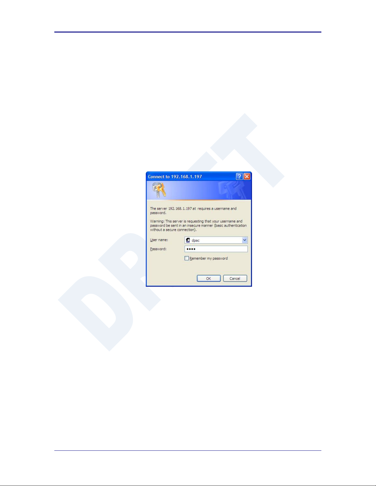
Quatech, Inc. AirborneDirect™ User Manual
15.0 Using the Web Interface
The AirborneDirect™ Device Servers and Wireless Adapters include a web interface that
provides access to module status, parameter modification and certificate and
configuration file management. To use the web interface follow the steps outlined in
section 14.0 to establish the IP address of the module. Once the IP address is known
open a web browser and enter the IP address of the module in the URL window.
The web interface currently supports Internet Explorer v6.0 thru 8.0, Firefox v3.x, Opera
v9.6+ and Chrome v4.0+.
When the authentication request is returned enter:
Figure 9 - Website Login
Username: dpac
Password: dpac
After successfully authenticating with the module, you will be logged into the web server.
If this is the first time you have accessed the device the Express Setup page will be
displayed see section 16.0 for configuration of the device using this page. If you have
previously configured the device the default home page will be displayed (See Figure 10),
from here you can update device settings if required. A quick overview of the web
interface follows.
44 2/21/2011 100-8510-110
Page 45
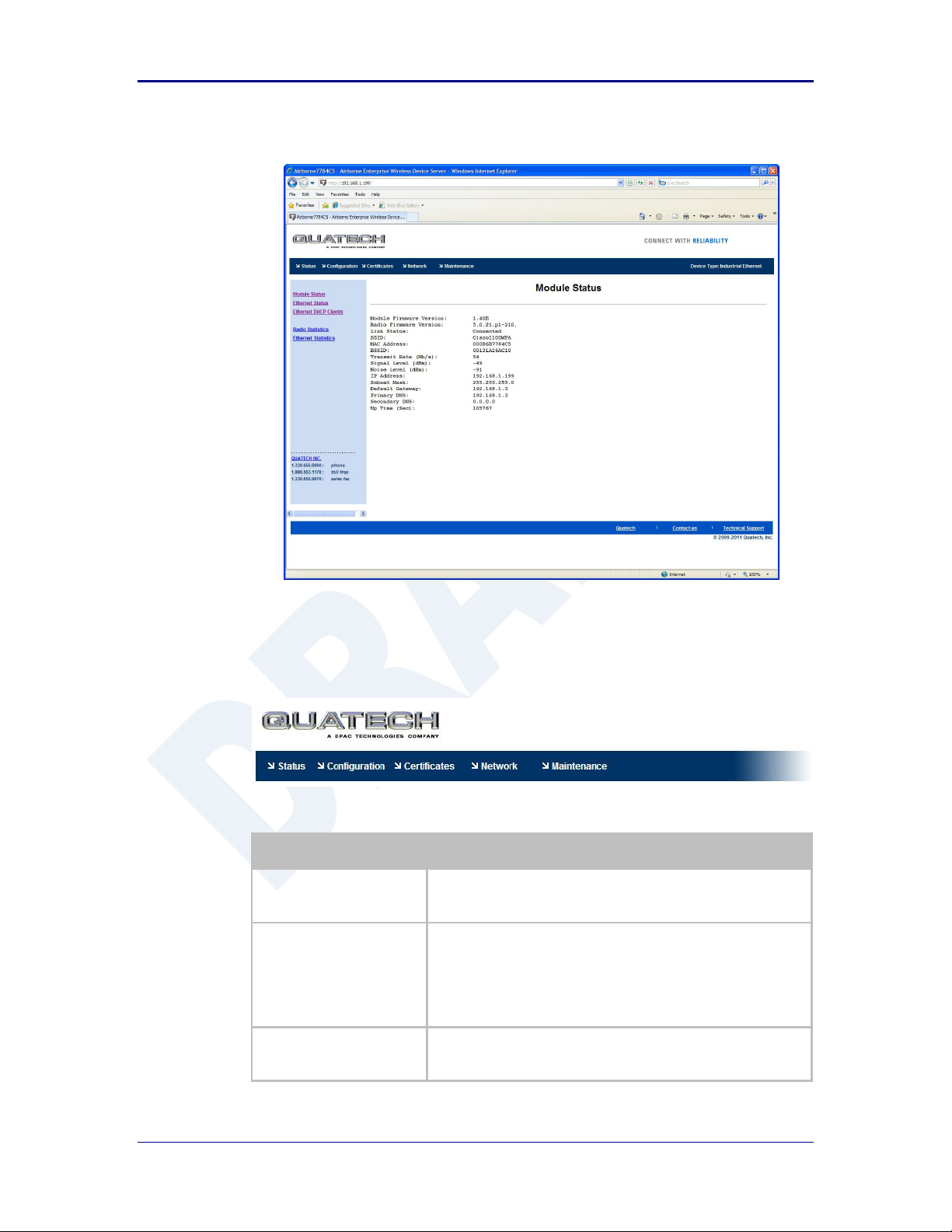
AirborneDirect™ Users Guide Quatech, Inc.
Title
Description
Status
Provides status and performance characteristics for the network
interfaces available. Includes connection status, radio and
Ethernet statistics.
Configuration
Allows viewing and configuration of all the interface settings
including wireless LAN, network connectivity, security, FTP client,
serial port and web server.
Includes the interface for delivery of OEM and user configuration
files, as well as management and viewing of current
configurations.
Certificates
This menu item provides the interface for certificate delivery and
management. Included in this section are the abilities to view
resident certificates, upload and delete certificates.
Figure 10 - Default Home Page
15.1 Navigation Bar
Figure 11 - Website Navigation Bar
Table 19 - Navigation Bar Items
100-8510-110 2/21/2011 45
Page 46

Quatech, Inc. AirborneDirect™ User Manual
Title
Description
Network
With this section it is possible to locate other Airborne Device
Server modules on the current network.
It is also possible to scan for available Access Points.
Maintenance
This section allows the updating of the modules firmware. You can
also revert the device settings to OEM defaults and restart the
module remotely.
The module locate function is also enabled in this section.
15.2 Feature Links
Each Navigation Bar link has a set of Features/Fields it allows access to. These
are different for each Navigation option and change for different device
selections. The Feature Links are located in the left hand panel of the web page
(See Figure 12).
Figure 12- Feature Links
15.3 Navigating the Website
A standard web page looks like Figure 13. The navigation bar runs along the top
of the page, page specific feature links are list in the left hand pane of the page
and the specific parameters are shown in the main display panel.
46 2/21/2011 100-8510-110
Page 47

AirborneDirect™ Users Guide Quatech, Inc.
Note that the changes to the parameters will not be applied until a module restart
(reboot) has been completed.
Figure 13 - Airborne Web Page
To select any of the items, move your cursor over the item and press the Left
Hand mouse button. The items in the Navigation bar and the Feature Links are
hyperlinks and will cause the mouse cursor to change form an arrow pointer to a
finger pointer when placed over them.
To find out what a specific field does move the cursor over the field and hover for
approximately a second. A help balloon will appear and will provide details on the
function of the field and its valid range of values.
15.4 Updating a Field
To update a field, select the field by pressing the Left Hand mouse button. Then
either type in the appropriate content or select form the pull down menu.
Once you have finished modifying parameters, scroll to the bottom of the page
and press the Commit button. The page will then indicate the changes have
been completed successfully, you can then return to the configuration page by
pressing the Reload button or restart the module by pressing the Reboot button.
Before the Commit button has been pressed, all modified fields can be returned
to their original state by pressing the Cancel button.
100-8510-110 2/21/2011 47
Page 48

Quatech, Inc. AirborneDirect™ User Manual
Step
Description
Navigation Bar
Select Certificates
You will see a list of certificates currently resident on the
module when you enter the Certificate File List window.
Feature Link
Select Upload Certificates
You will see a window open with field to enter the location
of the certificate you want to upload.
Press Browse... Button
This will open a dialog box in which you can locate the
certificate you wish to upload to the module. Select the
Certificate file and press Open.
This will return you to the Certificate Upload window and
will have entered the location and file name of the
certificate you wish to upload in the field next to the
Browse… button.
Press Upload Certificate
You will then see a notice that the certificate has been
successfully uploaded to the module.
Press List certificates Files
This will show the current certificates resident on the
module and will include the file just uploaded.
15.5 Uploading Certificates
Adding certificates to the Airborne Device Server module is very easy when
using the web interface.
Figure 14 - upload Certificate Web page
Table 20 - Uploading Certificates
15.6 Upload Configuration Files
The Airborne Device Server module supports both OEM and User configuration
files for provisioning the module. Delivery of these configuration files can be
performed through the web interface. A full description of these files can be found
in the Airborne CLI manual.
48 2/21/2011 100-8510-110
Page 49

AirborneDirect™ Users Guide Quatech, Inc.
Step
Description
Navigation Bar
Select Configuration
You will see major WLAN parameters displayed.
Feature Link
Select Upload Configuration File
You will see a window open with field to enter the
location of the configuration you want to upload, along
with a choice of OEM or User Configuration.
Press Browse... Button
This will open a dialog box in which you can locate the
certificate you wish to upload to the module. Select the
configuration file and press Open.
This will return you to the Configuration Upload window
and will have entered the location and file name of the
certificate you wish to upload in the field next to the
Browse… button.
Select User or OEM Configuration
This defines the configuration you are installing. OEM
Configurations will survive a factory reset, User will not.
Press Upload Configuration
You will then see a notice that the configuration has
been successfully uploaded to the module.
Press List Configuration Files
This will show the current configuration files resident on
the module and will include the file just uploaded.
*
Uploading a configuration file will overwrite any configuration file already stored on
the module. This will cause a change in configuration when a module restart is
performed.
IMPORTANT: Confirm that the OEM or USER settings in the configuration files will
allow the user to communicate with the module after the upload and a restart has
been completed.
To upload configuration files follow the steps in Table 21.
Figure 15 - Upload Configuration Web Page
Table 21 - Uploading Configurations
100-8510-110 2/21/2011 49
Page 50

Quatech, Inc. AirborneDirect™ User Manual
15.7 Updating Firmware
The module’s firmware may be updated using the web interface. Please refer to
Table 22 for the procedure to do this.
Updating the firmware will not alter any existing configuration files or certificates
loaded on the module.
You will first need to obtain the version of firmware you wish to install from the
Quatech website or Quatech technical support. The firmware will be a binary
image file (.img) and indicate the version of the firmware in the file name.
Once you have obtained the firmware, save the firmware image to a location on
the system you are browsing the module from, or a location accessible to the
system you are browsing the module from.
Figure 16 - Firmware Update Page
50 2/21/2011 100-8510-110
Page 51

AirborneDirect™ Users Guide Quatech, Inc.
Step
Description
Navigation Bar
Select Maintenance
This will open a window showing the current module
status.
Feature Link
Select Update Module Firmware
You will see a window open with field to enter the
location of the module firmware you want to upload.
The current firmware version number is displayed at the
top of the page.
Figure 17 - Firmware Update in Progress
Figure 18 - Firmware Update Complete
Table 22 - Updating Firmware
100-8510-110 2/21/2011 51
Page 52

Quatech, Inc. AirborneDirect™ User Manual
Step
Description
Press Browse... Button
This will open a dialog box in which you can locate the
firmware image you wish to upload to the module.
Select the firmware image file and press Open.
This will return you to the Upload Firmware window and
will have entered the location and file name of the
firmware image you wish to upload in the field next to
the Browse… button.
Press Load New Firmware
You will then see a notice that the firmware upload has
begun (Figure 17).
When the upload has been completed successfully and
the firmware updated w window indicating this will be
shown (Figure 18).
Press Reboot
This will restart the module and the new firmware will
be loaded.
DO NOT REMOVE POWER FROM THE MODULE DURING THE
FIRMWARE UPDATE.
This may cause the device to become non-operational. If this happens please contact
Quatech Technical Support.
52 2/21/2011 100-8510-110
Page 53
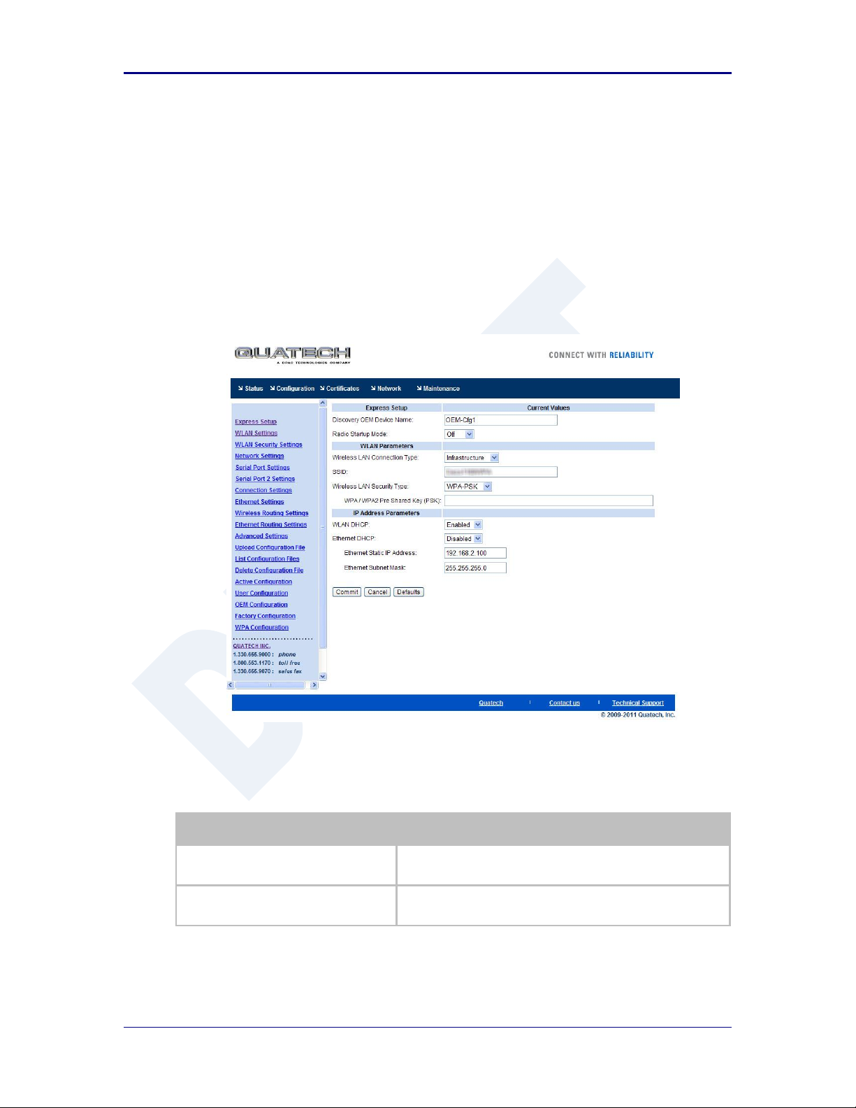
AirborneDirect™ Users Guide Quatech, Inc.
Step
Description
Navigation Bar
Select Configuration
You will see a group of fields under the banner of WLAN
Parameters.
Feature Link
Select Express Setup
This step is optional. If this is the first time the device has been
configured this page will automatically be displayed.
16.0 Express Setup Configuration Page
When the device’s web interface is accessed for the first time an Express Setup page will
be shown. This page is designed to allow a quick device set-up by presenting the most
popular device configuration options in a single location. For more advanced
configurations the full set of options are available in the feature links (left-hand column).
The Express Setup web page will display the necessary fields based upon the selections
made during configuration. The Express Setup page looks like (Figure 19):
Figure 19 - Express Setup Page
To configure the device for operation each field must be configured correctly. The
following steps should be taken to configure the device (Note: not all fields will be visible):
100-8510-110 2/21/2011 53
Table 23 - Express Page Setup
Page 54

Quatech, Inc. AirborneDirect™ User Manual
Step
Description
Select Discovery OEM Device Name
This parameter allows you to name the device uniquely or
group into a functional set. When device discovery is used this
name identifies the found device.
If you wanted to uniquely identify the device you could mark it
with a label e.g. Dev1, and then enter Dev1 in this field. When
the device is found it will identify itself as Dev1.
Alternately you could indicate the type of equipment the device
is attached to e.g. Haas TL-2 (CNC Turning Center), by giving
the unit a name like Haas_TL_2. When discovered you can then
identify the device you are accessing.
Enter the text string is you wish to change the default value.
This field is optional.
Select Radio Startup Mode
Select On from the drop down menu for the radio to operate.
Select Wireless LAN Connection Type
If you are using Access Points make sure this is set to
Infrastructure from the drop down menu.
If you want to use AdHoc set this accordingly. Additional
settings may be required to fully configure for AdHoc mode,
these are covered if section 17.2.
Select SSID
Enter the name of the wireless network you wish to access. This
field is case sensitive.
Select Wireless LAN Security Type
Select the security type the wireless network you wish to access
is using.
Depending upon the option you choose you may have to enter
additional information. Once you have selected the security type
the required inputs will be displayed. All displayed fields must
be completed.
If the security type is not in the available selections more are
available in the
WLAN Security Settings
page. If you choose to
use this page make sure you commit the change before
selecting the
WLAN Security Settings
page.
Select WLAN DHCP
If your WLAN network uses DHCP to assign IP addresses to the
wireless clients, select Enabled from the drop down menu.
If you are using static IP addresses select disabled from the
drop down menu. WLAN Static IP and WLAN Subnet Mask
will need to be entered.
Select Ethernet DHCP
If the Ethernet network connected to the Ethernet port uses
DHCP to assign IP addresses to the wired clients, you should
select Enabled from the drop down menu.
If you are using static IP addresses you should select Disabled
from the drop down menu. Ethernet Static IP and Ethernet
Subnet Mask will need to be entered.
Important: This field is only used if the Ethernet interface is
set as a client (default for Serial devices). If set as a router the
field is ignored. See section 21.0 for a full description of
configuring the unit as an Ethernet router.
Select WLAN Static IP
This field defines the static IP address for the wireless interface.
This address is only used if the WLAN DHCP is disabled or
DHCP failed.
Default: 192.168.10.1
Select WLAN Subnet Mask
This field defines the subnet mask used by the wireless
interface.
This mask is only used if the WLAN DHCP is disabled or DHCP
failed.
Default: 255.255.255.0
54 2/21/2011 100-8510-110
Page 55

AirborneDirect™ Users Guide Quatech, Inc.
Step
Description
Select Ethernet Static IP
This field defines the static IP address for the Ethernet
interface. When configured as a serial device server (Ethernet
interface is in client mode) this address is only used if the
Ethernet DHCP is disabled or DHCP failed.
Default: 192.168.2.100
Select Ethernet Subnet Mask
This field defines the subnet mask used by the Ethernet
interface. When configured as a serial device server (Ethernet
interface is in client mode) this mask is only used if the
Ethernet DHCP is disabled or DHCP failed.
Default: 255.255.255.0
Press Commit [Button]
Saves changes to the device.
Optional
Press Reload [Button]
Reloads the Express Settings page. Select this is you have
further configuration options to change.
Optional
Press Restart [Button]
Restarts the device. After the device as rebooted it will attempt
to authenticate to the configured network. As long as the
network is in range the wireless interface will connect.
If the network is using DHCP then an IP address will be
assigned to the WLAN interface and IP connectivity is possible
over the WLAN network.
If the network is using static IP addresses it will be necessary to
configure the network interface, see the next step.
The web interface supports advanced configuration of the device through the additional
pages available. The following sections provide guidance on how to use these pages for
specific configurations.
100-8510-110 2/21/2011 55
Page 56

Quatech, Inc. AirborneDirect™ User Manual
Step
Description
Navigation Bar
Select Configuration
You will see a group of fields under the banner of
WLAN Parameters.
Feature Link
Select WLAN Settings
This step is optional. The default home page for the
Configuration link in the Navigation Bar is
WLAN Settings.
Select Radio Startup Mode
Select On from the drop down list.
Select Wireless LAN Connection Type
Select the Infrastructure form the drop down list.
Select SSID
Enter the name of the wireless network you want
the device to use. This cannot include spaces.
Select Wireless LAN Region
Select the most appropriate region for the
deployment location of the device.
Press Commit [Button]
Saves changes to the device.
Press Reload [Button]
Reloads the WLAN Settings page.
Feature Link
Select WLAN Security Settings
The wireless interface is now configured however
most wireless networks use security to protect the
network and users from unauthorized use.
Selecting WLAN Security Settings will allow us to
configure the devices security settings for the
network. This is covered in section 18.0.
17.0 Configuring the Wireless Interface
The following section will outline how to configure the wireless interface for both
infrastructure and AdHoc networks.
17.1 Configuring for Infrastructure Networks
Infrastructure networks use Access Point and/or Wireless Routers to provide
wireless access to a network. Each wireless network is identified by a name
referred to as the SSID (Service Set IDentifier). To configure the device with the
necessary parameters to operate with an Infrastructure network use the following
steps.
Table 24 - Configuring Wireless Interface - Infrastructure
17.2 Configuring for AdHoc Networks
AdHoc networks use peer-to-peer connection to create a local wireless network.
These can be useful when no infrastructure (AP) is available. Each wireless
network is identified by a name referred to as the ESSID (Extended Service Set
IDentifier). To configure the device with the necessary parameters to operate
with an AdHoc use the following steps.
56 2/21/2011 100-8510-110
Page 57

AirborneDirect™ Users Guide Quatech, Inc.
Step
Description
Navigation Bar
Select Configuration
You will see a group of fields under the banner of
WLAN Parameters.
Feature Link
Select WLAN Settings
This step is optional. The default home page for the
Configuration link in the Navigation Bar is
WLAN Settings.
Select Radio Startup Mode
Select On from the drop down list.
Select Wireless LAN Connection Type
Select the AdHoc form the drop down list.
Select Wireless LAN Channel
This determines the 802.11 channel that the device
will use when it establishes a connection with
another device in the AdHoc network.
Select a channel that is clear, i.e. one which has no
other 802.11 network using it. It is not necessary for
all devices in a single AdHoc network to have the
same channel number selected.
Select SSID
Enter the name of the wireless network you want
the device to use. This cannot include spaces.
Select Wireless LAN Region
Select the most appropriate region for the
deployment location of the device.
Press Commit [Button]
Saves changes to the device.
Press Reload [Button]
Reloads the WLAN Settings page.
Feature Link
Select WLAN Security Settings
The wireless interface is now configured however
most wireless networks use security to protect the
network and users from unauthorized use.
Selecting WLAN Security Settings will allow us to
configure the devices security settings for the
network. This is covered in section XX.
Feature Link
Select Network Settings
The wireless interface is now configured however
most AdHoc networks do not have a DHCP server
available to provide IP address to the devices in the
network. It therefore necessary to assign a static IP
address to the wireless interface.
Selecting Network Settings will allow us to
configure the device with a static IP address. This is
covered in section 19.0.
Table 25 - Configuring Wireless Interface - AdHoc
100-8510-110 2/21/2011 57
Page 58

Quatech, Inc. AirborneDirect™ User Manual
Step
Description
Navigation Bar
Select Configuration
You will see a group of fields under the banner of
WLAN Parameters.
Feature Link
Select WLAN Security Settings
The wireless interface must be configured before
configuring the security for the network.
A page showing the range of security options and
fields is displayed.
Select Wireless LAN Security
Select WEP64 or WEP128 from the drop down list.
The options identify the length of the key that will
be used with the security protocol.
If WEP64 is selected the key length is 10 digits.
If WEP128 is selected the key length is 26 digits.
Select Authentication Type
Select Auto from the drop down list. This field
should not need to be changed. Only modify if you
have been specifically told to by the network
administrator.
Select Default WEP Key
Select the key number that matches the selection
used by the AP’s in the wireless network. This must
match for authentication to be successful.
There must be a valid key in the selected key
number field.
Select WEP Key 1 - 4
Select the key field that matches the one selected in
Default WEP Key field. Enter the key exactly as it is
entered into the AP.
If WEP64 is selected the key length is 10 digits.
If WEP128 is selected the key length is 26 digits.
More than one key field can be completed.
Press Commit [Button]
Saves changes to the device.
Optional
Press Reload [Button]
Reloads the WLAN Settings page. Select this is
you have further configuration options to change.
18.0 Configuring the Security Settings
Almost all 802.11 networks will use some sort of security to protect the network from
unauthorized use. There are many types of security options available. The following
section will cover how to configure the device for the most popular options. If your
security configuration is not covered, further details can be found in the Airborne
Enterprise CLI Reference Manual.
18.1 Configuring for WEP Security
Although an old protocol WEP is still used by many networks. The Airborne
device supports many variations of WEP however we will only cover the most
popular in the following table. If the basic 64 or 128 bit WEP configuration does
not work please refer to the Airborne Enterprise CLI Reference Manual for the
other options available.
Table 26 - Configuring for WEP Security
58 2/21/2011 100-8510-110
Page 59

AirborneDirect™ Users Guide Quatech, Inc.
Step
Description
Optional
Press Restart [Button]
Restarts the device. After the device as rebooted it
will attempt to authenticate to the configured
network. As long as the network is in range the
wireless interface will connect.
If the network is using DHCP then an IP address will
be assigned to the WLAN interface and IP
connectivity is possible over the WLAN network.
If the network is using static IP addresses it will be
necessary to configure the network interface, see
the next step.
Feature Link
Select Network Settings
The wireless interface is now configured however if
the WLAN network does not have a DHCP server
available to provide IP address to the device, it
necessary to assign a static IP address to the
wireless interface.
Selecting Network Settings will allow us to
configure the device with a static IP address. This is
covered in section 19.0.
Step
Description
Navigation Bar
Select Configuration
You will see a group of fields under the banner
of WLAN Parameters.
Feature Link
Select WLAN Security Settings
The wireless interface must be configured
before configuring the security for the network.
A page showing the range of security options
and fields is displayed.
Select Wireless LAN Security
Select WPA-PSK from the drop down list.
Select WPA Protocol Version
Select Auto from the drop down list. This field
should not need to be changed. Only modify if
you have been specifically told to by the
network administrator.
Select WPA/WPA2 Pre Shared Key (PSK)
Enter the PreShared Key used by the AP. The
PSK is case sensitive and must be entered
exactly as it is in the AP.
The PSK cannot include spaces.
Press Commit [Button]
Saves changes to the device.
Optional
Press Reload [Button]
Reloads the WLAN Settings page. Select this
is you have further configuration options to
change.
18.2 Configuring for WPA-PSK Security
This security type is a very popular type and is easy to configure. Most often
used in SOHO and home environments, some enterprise networks do use it.
Table 27 - Configuring for WPA Security
100-8510-110 2/21/2011 59
Page 60

Quatech, Inc. AirborneDirect™ User Manual
Step
Description
Optional
Press Restart [Button]
Restarts the device. After the device as
rebooted it will attempt to authenticate to the
configured network. As long as the network is
in range the wireless interface will connect.
If the network is using DHCP then an IP
address will be assigned to the WLAN interface
and IP connectivity is possible over the WLAN
network.
If the network is using static IP addresses it will
be necessary to configure the network
interface, see the next step.
Feature Link
Select Network Settings
The wireless interface is now configured
however if the WLAN network does not have a
DHCP server available to provide IP address to
the device, it necessary to assign a static IP
address to the wireless interface.
Selecting Network Settings will allow us to
configure the device with a static IP address.
This is covered in section 19.0.
Step
Description
Navigation Bar
Select Configuration
You will see a group of fields under the banner
of WLAN Parameters.
Feature Link
Select WLAN Security Settings
The wireless interface must be configured
before configuring the security for the network.
A page showing the range of security options
and fields is displayed.
Select Wireless LAN Security
Select WPA2-PSK from the drop down list.
Select WPA/WPA2 Pre Shared Key (PSK)
Enter the PreShared Key used by the AP. The
PSK is case sensitive and must be entered
exactly as it is in the AP.
The PSK cannot include spaces.
Press Commit [Button]
Saves changes to the device.
Optional
Press Reload [Button]
Reloads the WLAN Settings page. Select this
is you have further configuration options to
change.
18.3 Configuring for WPA2-PSK Security
This security type is a very popular type and is easy to configure. Most often
used in SOHO and home environments, WPA2-PSK is starting to be widely used
by enterprise networks.
Table 28 - Configuring for WPA2 Security
60 2/21/2011 100-8510-110
Page 61

AirborneDirect™ Users Guide Quatech, Inc.
Step
Description
Optional
Press Restart [Button]
Restarts the device. After the device as
rebooted it will attempt to authenticate to the
configured network. As long as the network is
in range the wireless interface will connect.
If the network is using DHCP then an IP
address will be assigned to the WLAN interface
and IP connectivity is possible over the WLAN
network.
If the network is using static IP addresses it will
be necessary to configure the network
interface, see the next step.
Feature Link
Select Network Settings
The wireless interface is now configured
however if the WLAN network does not have a
DHCP server available to provide IP address to
the device, it necessary to assign a static IP
address to the wireless interface.
Selecting Network Settings will allow us to
configure the device with a static IP address.
This is covered in section 19.0.
Step
Description
Navigation Bar
Select Configuration
You will see a group of fields under the banner
of WLAN Parameters.
Feature Link
Select WLAN Security Settings
The wireless interface must be configured
before configuring the security for the network.
A page showing the range of security options
and fields is displayed.
Select Wireless LAN Security
Select PEAP from the drop down list.
Select EAP Identity
Enter the RADIUS server account name
provided by the network administrator.
If a Windows domain server is being used for
authentication the server domain must be
included in the EAP Ident field
Select EAP Password
Enter the RADIUS server account password for
the EAP Ident.
Select EAP Phase 1 String
Enter peaplabel=0
Select EAP Phase 1 String
Enter auth=MSCHAPV2
18.4 Configuring for PEAP Security
This security type is a very popular type for enterprise networks. Actual use of
the security protocol requires the network is using a RADIUS server for device
authentication, depending upon the security policies of the network this protocol
supports authentication with and without a CA certificate.
The Airborne device supports PEAPv0 using both WPA (TKIP) and WPA2 (AESCCMP) encryption. The device will automatically use the most appropriate
encryption type to obtain authentication to the WLAN.
Table 29 - Configuring for PEAP Security
100-8510-110 2/21/2011 61
Page 62

Quatech, Inc. AirborneDirect™ User Manual
Step
Description
Select CA Certificate Filename
Enter the name of the Certificate Authority (CA)
certificate stored on the device.
Storing Certificates on the device is cover in
section 15.5.
If the network security does not require the use
of a CA certificate this field should be left
blank.
Press Commit [Button]
Saves changes to the device.
Optional
Press Reload [Button]
Reloads the WLAN Settings page. Select this
is you have further configuration options to
change.
Optional
Press Restart [Button]
Restarts the device. After the device as
rebooted it will attempt to authenticate to the
configured network. As long as the network is
in range the wireless interface will connect.
If the network is using DHCP then an IP
address will be assigned to the WLAN interface
and IP connectivity is possible over the WLAN
network.
If the network is using static IP addresses it will
be necessary to configure the network
interface, see the next step.
Feature Link
Select Network Settings
The wireless interface is now configured
however if the WLAN network does not have a
DHCP server available to provide IP address to
the device, it necessary to assign a static IP
address to the wireless interface.
Selecting Network Settings will allow us to
configure the device with a static IP address.
This is covered in section 19.0.
62 2/21/2011 100-8510-110
Page 63

AirborneDirect™ Users Guide Quatech, Inc.
The Ethernet configuration sections do not apply to devices that do not have an available
Ethernet port; these include but are not limited to the ABDG-SE-DP5XX product families.
Step
Description
Navigation Bar
Select Configuration
You will see a group of fields under the banner
of WLAN Parameters.
Feature Link
Select Network Settings
The wireless interface and security must be
configured before configuring the network
settings.
A page showing the range of network options
and fields, for both the WLAN and Ethernet
interfaces, is displayed.
Select WLAN DHCP
Select Enabled from the dropdown menu.
Optional
Select WLAN DHCP Name
Provides a method of uniquely identifying the
device in the DHCP lease table on the DHCP
server.
The default name is AirborneXXXXXX, where
XXXXXX matches the last 6 octets of the
WLAN interface MAC address.
Press Commit [Button]
Saves changes to the device.
19.0 Configuring Network Settings
Once the device is authenticated to a wireless network communication is possible,
however before TCP/IP connectivity can be achieved the device must obtain a valid IP
address on the WLAN and/or Ethernet interface.
The Airborne device supports both DHCP and Static IP addressing for both the WLAN
and Ethernet interfaces. The following sections cover the correct configuration for both
DHCP and Static IP addressing on the interfaces.
When the Ethernet interface is in client mode DHCP can be used on either the WLAN or
Ethernet interface but not on both interfaces at the same time.
The Ethernet interface configuration only applies when the interface is in client mode and
is being used by a serial device server. The configuration of the Ethernet interface when
being used with the Ethernet adapter (ABDG-ET) products is covered in section 21.0.
19.1 Configuring DHCP on WLAN Interface
DHCP enabled on the WLAN interface is the default configuration for the
Ethernet devices. For serial devices the default is DHCP disabled on the WLAN
interface. It requires that there is a DHCP server on the WLAN network the
device has authenticated to and that the necessary network policies will allow the
server to lease an address to the Airborne™ device.
Table 30 - Configuring DHCP - WLAN
100-8510-110 2/21/2011 63
Page 64

Quatech, Inc. AirborneDirect™ User Manual
Step
Description
Optional
Press Reload [Button]
Reloads the Network Settings page. Select
this is you have further configuration options to
change.
Optional
Press Restart [Button]
Restarts the device. After the device as
rebooted it will attempt to authenticate to the
configured network. As long as the network is
in range the wireless interface will connect.
Once authenticated the network should lease
an IP address to the WLAN interface and IP
connectivity is possible over the WLAN
network.
Step
Description
Navigation Bar
Select Configuration
You will see a group of fields under the banner
of WLAN Parameters.
Feature Link
Select Ethernet Settings
The wireless interface and security must be
configured before configuring the Ethernet
settings.
A page showing the range of Ethernet options
and fields, setting the mode of operation for
the Ethernet interface is done in this page.
Select Ethernet Role
Select Client from the drop down menu.
Press Commit [Button]
Saves changes to the device.
Press Reload [Button]
Reloads the Ethernet Settings page.
Feature Link
Select Network Settings
The wireless interface and security must be
configured before configuring the network
settings.
A page showing the range of network options
and fields, for both the WLAN and Ethernet
interfaces, is displayed.
Select Ethernet DHCP
Select Enabled from the drop down menu.
Optional
Select WLAN DHCP Name
Provides a method of uniquely identifying the
device in the DHCP lease table on the DHCP
server.
The default name is AirborneXXXXXX, where
XXXXXX matches the last 6 hexadecimal digits
of the Ethernet interface MAC address.
19.2 Configuring DHCP on Ethernet Interface
DHCP enabled on the Ethernet interface is the default configuration for the serial
devices. The Ethernet interface must be in client mode for this setting to be used.
The Airborne Device does not support the ability to enable DHCP on the WLAN
and Ethernet interfaces simultaneously (when in client mode). Only one may
have DHCP enabled at a time. The other interface must be configured to use a
static IP address.
Table 31 - Configuring DHCP - Ethernet
64 2/21/2011 100-8510-110
Page 65

AirborneDirect™ Users Guide Quatech, Inc.
Step
Description
Press Commit [Button]
Saves changes to the device.
Optional
Press Reload [Button]
Reloads the Network Settings page. Select
this is you have further configuration options to
change.
Optional
Press Restart [Button]
Restarts the device. After the device as
rebooted it will attempt to authenticate to the
configured network. As long as the network is
in range the wireless interface will connect.
Once authenticated the network should lease
an IP address to the WLAN interface and IP
connectivity is possible over the WLAN
network.
Step
Description
Navigation Bar
Select Configuration
You will see a group of fields under the banner
of WLAN Parameters.
Feature Link
Select Network Settings
The wireless interface and security must be
configured before configuring the network
settings.
A page showing the range of network options
and fields, for both the WLAN and Ethernet
interfaces, is displayed.
Select WLAN DHCP
Select Disable from the drop down menu.
Select WLAN Static IP Address
Enter the assigned static IP address.
The address must be in the format:
XXX.XXX.XXX.XXX
Select Subnet Mask
Enter the subnet mask for the network.
The mask must be in the format:
XXX.XXX.XXX.XXX
Select Gateway IP Address
Enter the assigned Gateway IP address.
The address must be in the format:
XXX.XXX.XXX.XXX
Press Commit [Button]
Saves changes to the device.
Optional
Press Reload [Button]
Reloads the Network Settings page. Select
this is you have further configuration options to
change.
19.3 Configuring a Static IP Address on WLAN Interface
Static IP addresses on the WLAN interface is the default configuration for serial
devices. It is important to verify the address being entered is unique to the
device when on the network.
Table 32 - Configuring Static IP - WLAN
100-8510-110 2/21/2011 65
Page 66

Quatech, Inc. AirborneDirect™ User Manual
Step
Description
Optional
Press Restart [Button]
Restarts the device. After the device as
rebooted it will attempt to authenticate to the
configured network. As long as the network is
in range the wireless interface will connect.
Once authenticated the network will use the
assigned static IP address on the WLAN
interface making IP connectivity possible over
the WLAN network.
Step
Description
Navigation Bar
Select Configuration
You will see a group of fields under the banner
of WLAN Parameters.
Feature Link
Select Ethernet Settings
The wireless interface and security must be
configured before configuring the Ethernet
settings.
A page showing the range of Ethernet options
and fields, setting the mode of operation for
the Ethernet interface is done in this page.
Select Ethernet Role
Select Client from the drop down menu.
Press Commit [Button]
Saves changes to the device.
Press Reload [Button]
Reloads the Ethernet Settings page.
Feature Link
Select Network Settings
The wireless interface and security must be
configured before configuring the network
settings.
A page showing the range of network options
and fields, for both the WLAN and Ethernet
interfaces, is displayed.
Select Ethernet DHCP
Select Disable from the drop down menu.
Select Ethernet Static IP Address
Enter the assigned static IP address.
The address must be in the format:
XXX.XXX.XXX.XXX
Select Ethernet Subnet Mask
Enter the subnet mask for the network.
The mask must be in the format:
XXX.XXX.XXX.XXX
19.4 Configuring a Static IP Address on Ethernet Interface
This is not the default configuration for the Ethernet interface. It is important to
verify the address being entered is unique to the device when on the network.
The Airborne Device does not support the ability to enable DHCP on the WLAN
and Ethernet interfaces simultaneously (when in client mode). Only one may
have DHCP enabled at a time, the other interface must be configured to use a
static IP address.
Table 33 - Configuring Static IP - Ethernet
66 2/21/2011 100-8510-110
Page 67

AirborneDirect™ Users Guide Quatech, Inc.
Step
Description
Select Ethernet Gateway IP Address
Enter the assigned Gateway IP address.
The address must be in the format:
XXX.XXX.XXX.XXX
Press Commit [Button]
Saves changes to the device.
Optional
Press Reload [Button]
Reloads the Network Settings page. Select
this is you have further configuration options to
change.
Optional
Press Restart [Button]
Restarts the device. After the device as
rebooted it will attempt to authenticate to the
configured network. As long as the network is
in range the wireless interface will connect.
Once authenticated the network will use the
assigned static IP address on the Ethernet
interface making IP connectivity possible over
the Ethernet network.
100-8510-110 2/21/2011 67
Page 68

Quatech, Inc. AirborneDirect™ User Manual
Step
Description
Navigation Bar
Select Configuration
You will see a group of fields under the banner
of WLAN Parameters.
Feature Link
Select Connection Settings
The wireless interface and security must be
configured before configuring the Ethernet
settings.
A page showing the configuration options for
TCP/IP and UDP connections to the device.
Configuration of Telnet, HTTP and SSH ports is
possible through this page.
Select Telnet Port
Enter the port number you wish to use for a
telnet (TCP/IP) connection to the device.
The default 23 should only be changed if your
application requires access to port 23 for
another purpose.
Press Commit [Button]
Saves changes to the device.
Press Reload [Button]
Reloads the Connection Settings page.
20.0 Configuring Serial Device Server
The ABDG-SE-DP5XX/IN5XXX devices are shipped preconfigured for use as Serial
Device Servers. All that is required is configuration of the WLAN parameters and security
protocols; however the following section will cover the full configuration of a Serial Device
Server to aid in the installation and deployment of the units.
If the Windows Virtual COM port driver is being used with the device, configure only the
WLAN network parameters and security protocols through the web interface. All other
parameters will be controlled by the VCOM driver. Installation and configuration of the
VCOM driver is covered in section 21.0.
The following section shows how to manually configure the unit to accept TCP/IP
connections and automatically set-up a data tunnel with one of the serial ports. The
configuration is independent of the source of the request, as the tunnel ports are
available to both the WLAN and Ethernet interfaces.
The Airborne devices support conditional tunnel binding based upon rules included in the
configuration. The major options will be included.
20.1 Configuring Serial Port for Access on Telnet Port
A data tunnel can be made using the device’s telnet port as the network
connection port. This does require authenticating with the device and manually
initiating the tunnel connection. Configuring the device to support this approach
to establishing a data tunnel is covered in the following table.
Table 34 – Configure Data Tunnel on Telnet Port
68 2/21/2011 100-8510-110
Page 69

AirborneDirect™ Users Guide Quatech, Inc.
Step
Description
Feature Link
Select Serial Port 1 Settings/Serial Port 2
Settings
The wireless interface and security must be
configured before configuring the Ethernet
settings.
Displays a page showing the serial port
configuration, setting the default mode of
operation for the serial interface is done in this
page.
Select Serial CLI Default Mode
Select Listen from the drop down menu.
Press Commit [Button]
Saves changes to the device.
Optional
Press Reload [Button]
Reloads the Serial Port X Settings page.
Select this is you have further configuration
options to change.
Optional
Press Restart [Button]
Restarts the device. After the device as
rebooted it will attempt to authenticate to the
configured network. As long as the network is
in range the wireless interface will connect.
Once authenticated the network it is possible
for a TCP/IP connection to be made on the
Telnet port.
Step
Description
Open TCP socket to device
Using the WLAN IP Address and configured
telnet port number.
Authenticate with device
auth dpac dpac
Any user level above L5 can authenticate with
the unit.
Device responds OK
Open data tunnel to serial port
pass-x
Where x can be p1, p2 or any.
p1 or p2 binds to the indicated serial port, as
long as the serial port is in listen mode and
does not already have a data tunnel open.
any binds to the first serial port which is in
listen mode and does not already have a data
tunnel open.
To establish a data tunnel and gain access to the serial data from the WLAN or
Ethernet interface follow the steps in Table 35.
Table 35 - Data Tunnel using Telnet Port
20.2 Configuring Serial Port 1 for Access on Tunnel Port
A data tunnel can be made using the devices tunnel port as the network
connection port. This does not require authenticating with the device and
automatically initiates the tunnel connection. Configuring the device to support
this approach to establishing a data tunnel is covered in the following table.
100-8510-110 2/21/2011 69
Page 70

Quatech, Inc. AirborneDirect™ User Manual
Step
Description
Navigation Bar
Select Configuration
You will see a group of fields under the banner
of WLAN Parameters.
Feature Link
Select Connection Settings
The wireless interface and security must be
configured before configuring the Ethernet
settings.
A page showing the configuration options for
TCP/IP and UDP connections to the device.
Configuration of Telnet, HTTP and SSH ports is
possible through this page.
Select Tunnel Enabled
Select Enabled.
Select Tunnel Port
Enter the port to be used for the tunnel.
Default is 8023, this should only be changed if
a port is already defined for the application
server or it is already being used by another
service.
Select Tunnel Mode
Select TCP from drop down menu.
Press Commit [Button]
Saves changes to the device.
Press Reload [Button]
Reloads the Connection Settings page.
Feature Link
Select Serial Port Settings
The wireless interface and security must be
configured before configuring the Ethernet
settings.
Displays a page showing the serial port
configuration, setting the default mode of
operation for the serial interface is done in this
page.
Select Serial CLI Default Mode
Select Listen from the drop down menu.
Press Commit [Button]
Saves changes to the device.
Optional
Press Reload [Button]
Reloads the Serial Port Settings page. Select
this is you have further configuration options to
change.
Optional
Press Restart [Button]
Restarts the device. After the device as
rebooted it will attempt to authenticate to the
configured network. As long as the network is
in range the wireless interface will connect.
Once authenticated the network it is possible
for a TCP/IP connection to be made on the
Telnet port.
Step
Description
Open TCP socket to device
Using the WLAN IP Address and configured
tunnel port number for Serial Port 1 (Default
8023).
Table 36 – Configure Data Tunnel on Serial Port 1 Tunnel Port (TCP)
To establish a data tunnel and gain access to the serial data from the WLAN or
Ethernet interface follow the steps in Table 37.
70 2/21/2011 100-8510-110
Table 37 - Data Tunnel using Tunnel Port on Serial Port 1
Page 71

AirborneDirect™ Users Guide Quatech, Inc.
Step
Description
Navigation Bar
Select Configuration
You will see a group of fields under the banner
of WLAN Parameters.
Feature Link
Select Connection Settings
The wireless interface and security must be
configured before configuring the Ethernet
settings.
A page showing the configuration options for
TCP/IP and UDP connections to the device.
Configuration of Telnet, HTTP and SSH ports is
possible through this page.
Select Tunnel Enabled – Serial Port 2
Select Enabled.
Select Tunnel Port – Serial Port 2
Enter the port to be used for the tunnel.
Default is 8024, this should only be changed if
a port is already defined for the application
server or it is already being used by another
service.
Select Tunnel Mode – Serial Port 2
Select TCP from drop down menu.
Press Commit [Button]
Saves changes to the device.
Press Reload [Button]
Reloads the Connection Settings page.
Feature Link
Select Serial Port 2 Settings
The wireless interface and security must be
configured before configuring the Ethernet
settings.
Displays a page showing the serial port
configuration, setting the default mode of
operation for the serial interface is done in this
page.
Select Serial CLI Default Mode
Select Listen from the drop down menu.
Press Commit [Button]
Saves changes to the device.
Optional
Press Reload [Button]
Reloads the Serial Port 2 Settings page.
Select this is you have further configuration
options to change.
Optional
Press Restart [Button]
Restarts the device. After the device as
rebooted it will attempt to authenticate to the
configured network. As long as the network is
in range the wireless interface will connect.
Once authenticated the network it is possible
for a TCP/IP connection to be made on the
Telnet port.
20.3 Configuring Serial Port 2 for Access on Tunnel Port
A data tunnel can be made using the devices tunnel port as the network
connection port. This does not require authenticating with the device and
automatically initiates the tunnel connection. Configuring the device to support
this approach to establishing a data tunnel is covered in the following table.
Table 38 – Configure Data Tunnel on Serial Port 2 Tunnel Port (TCP)
To establish a data tunnel and gain access to the serial data from the WLAN or
Ethernet interface follow the steps in Table 39.
100-8510-110 2/21/2011 71
Page 72

Quatech, Inc. AirborneDirect™ User Manual
Step
Description
Open TCP socket to device
Using the WLAN IP Address and configured
tunnel port number for Serial Port 2 (Default
8024).
Step
Description
Navigation Bar
Select Configuration
You will see a group of fields under the
banner of WLAN Parameters.
Feature Link
Select Connection Settings
The wireless interface and security must be
configured before configuring the Ethernet
settings.
A page showing the configuration options for
TCP/IP and UDP connections to the device.
Configuration of Telnet, HTTP and SSH ports
is possible through this page.
Select TCP Port
Enter the port on which the target server is
listening for TCP connections.
Select TCP Timeout
Enter the inactivity timeout in seconds, after
which the device will close the open data
tunnel on Serial Port 1.
The default 0 disables the timeout.
Select TCP Retry Time
Enter the period (in seconds) the device
should use to retry establishing the TCP
connection to the target server.
Select Primary TCP Target Server IP Address
Enter the IP address of the primary target
server.
The address must be in the format:
XXX.XXX.XXX.XXX
Optional
Select Secondary TCP Target Server IP
Address
Enter the IP address of the secondary target
server.
The address must be in the format:
XXX.XXX.XXX.XXX
This address will be used if the initial
attempts to connect to the primary server
fail. This field is optional.
Press Commit [Button]
Saves changes to the device.
Press Reload [Button]
Reloads the Connection Settings page.
Table 39 - Data Tunnel using Tunnel Port on Serial Port 2
20.4 Configuring Serial Port 1 as TCP Client
In this mode the device will attempt to initiate a TCP connection to a network
based server and establish a data tunnel with Serial Port 1 on a successful
network connection.
Table 40 - Configure Serial Port 1 as TCP Client
72 2/21/2011 100-8510-110
Page 73

AirborneDirect™ Users Guide Quatech, Inc.
Step
Description
Feature Link
Select Serial Port 1 Settings
The wireless interface and security must be
configured before configuring the Ethernet
settings.
Displays a page showing the serial port
configuration, setting the default mode of
operation for the serial interface is done in
this page.
Select Serial CLI Default Mode
Select Pass from the drop down menu.
Press Commit [Button]
Saves changes to the device.
Optional
Press Reload [Button]
Reloads the Serial Port 1 Settings page.
Select this is you have further configuration
options to change.
Optional
Press Restart [Button]
Restarts the device. After the device as
rebooted it will attempt to authenticate to
the configured network. As long as the
network is in range the wireless interface will
connect.
Once authenticated to the network it the
device will attempt to make a TCP
connection with primary target server, using
the configured port number.
Step
Description
Navigation Bar
Select Configuration
You will see a group of fields under the
banner of WLAN Parameters.
Feature Link
Select Connection Settings
The wireless interface and security must be
configured before configuring the Ethernet
settings.
A page showing the configuration options for
TCP/IP and UDP connections to the device.
Configuration of Telnet, HTTP and SSH ports
is possible through this page.
Select TCP Port – Serial Port 2
Enter the port on which the target server is
listening for TCP connections.
Select TCP Timeout – Serial Port 2
Enter the inactivity timeout in seconds, after
which the device will close the open data
tunnel on Serial Port 1.
The default 0 disables the timeout.
Select TCP Retry Time – Serial Port 2
Enter the period (in seconds) the device
should use to retry establishing the TCP
connection to the target server.
20.5 Configuring Serial Port 2 as TCP Client
In this mode the device will attempt to initiate a TCP connection to a network
based server and establish a data tunnel with Serial Port 2 on a successful
network connection.
Table 41 - Configure Serial Port 2 as TCP Client
100-8510-110 2/21/2011 73
Page 74

Quatech, Inc. AirborneDirect™ User Manual
Step
Description
Select Primary TCP Target Server IP Address
– Serial Port 2
Enter the IP address of the primary target
server.
The address must be in the format:
XXX.XXX.XXX.XXX
Optional
Select Secondary TCP Target Server IP
Address – Serial Port 2
Enter the IP address of the secondary target
server.
The address must be in the format:
XXX.XXX.XXX.XXX
This address will be used if the initial
attempts to connect to the primary server
fail. This field is optional.
Press Commit [Button]
Saves changes to the device.
Press Reload [Button]
Reloads the Connection Settings page.
Feature Link
Select Serial Port 2 Settings
The wireless interface and security must be
configured before configuring the Ethernet
settings.
Displays a page showing the serial port
configuration, setting the default mode of
operation for the serial interface is done in
this page.
Select Serial CLI Default Mode
Select Pass from the drop down menu.
Press Commit [Button]
Saves changes to the device.
Optional
Press Reload [Button]
Reloads the Serial Port 2 Settings page.
Select this is you have further configuration
options to change.
Optional
Press Restart [Button]
Restarts the device. After the device as
rebooted it will attempt to authenticate to
the configured network. As long as the
network is in range the wireless interface will
connect.
Once authenticated to the network it the
device will attempt to make a TCP
connection with primary target server, using
the configured port number.
74 2/21/2011 100-8510-110
Page 75

AirborneDirect™ Users Guide Quatech, Inc.
1
Run the Airborne Management System application. This was installed during the CD installation and a
menu item will be found in the Airborne folder located in the programs directory of your system.
When the application opens the following dialog will be displayed:
Select Group Name: manuf and enter Group Password: dpac
2
The AMC will load and discover the attached devices. Managed devices will show up under the device
type heading they belong to. To install a VCOM driver the device MUST have a serial port.
The device must be managed to install the VCOM driver. If the device you wish to install the VCOM with
is already managed skip to step 4.
21.0 Installing and Using the Airborne VirtualCOM Driver
Quatech supplies with its serial devices a virtual COM port device driver for the Microsoft
Windows operating system. This driver acts as a Virtual COM port for applications
requiring the use of a COM port for data communication. The driver redirects serial data
to a TCP/IP connection between the host computer and target Airborne™ device.
Installation of the VCOM driver is done using the Airborne Management Center™ (AMC).
The following Table 42 identifies the steps to complete the process of installing the
VCOM driver for a specific device. Once installed the host system will have additional
COM ports through which the system may communicate with the device attached to the
serial port on the Airborne™ device.
Table 42 - Install VCOM
100-8510-110 2/21/2011 75
Page 76
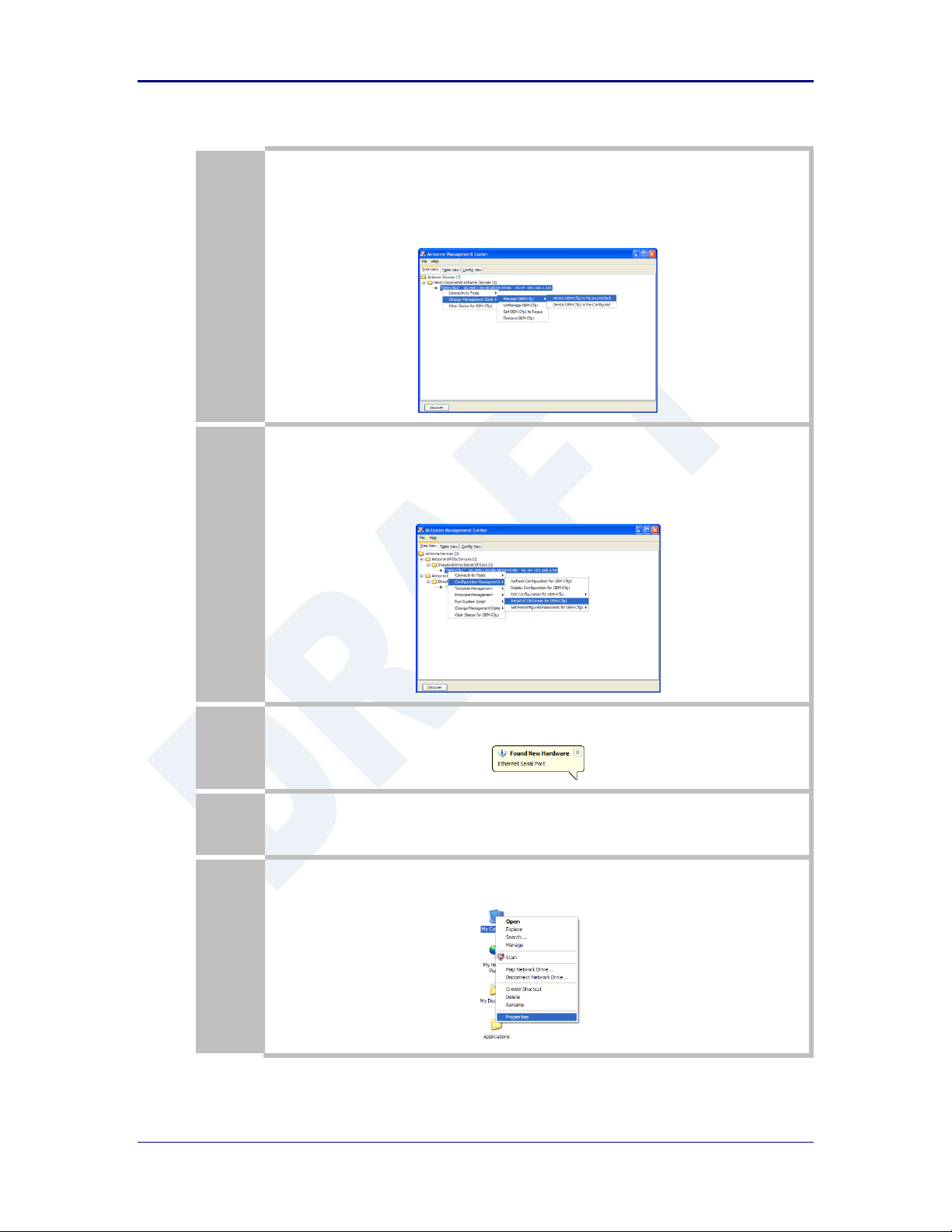
Quatech, Inc. AirborneDirect™ User Manual
3
Right Click the Unmanaged Device then:
1. Select Change Management State
2. Select Manage OEM-Cfg1
3. Select Device OEM-Cfg1 is Factory Default
4
The status of the device will move to managed and it will be displayed under the device type/group it
belongs too. To install the VCOM driver, right click the target device:
1. Select Configuration Management
2. Select Install VCOM Driver for OEM-Cfg1
5
The VCOM driver will then be installed. When completed the following message will be seen in the lower
right-hand corner.
6
The installed VCOM ports are now available for use.
7
To identify the VCOM ports right click My Computer.
Select Properties.
76 2/21/2011 100-8510-110
Page 77

AirborneDirect™ Users Guide Quatech, Inc.
8
Select the Hardware tab.
Select the Device Manager button.
9
Select the Ports (COM & LPT) group and the list of available COM ports will be shown. The VCOM ports
will be identified as Ethernet Serial Port (COMx), where x will be an integer. This COMx reference
identifies the VCOM to be used.
Note that if your unit is a dual serial port device, two VCOM ports will have been created.
10
To identify which VCOM port is assigned to which device right click the Ethernet Serial Port and select
Properties.
The Location label identifies the MAC address of the associated Airborne device.
Do not change the WLAN IP address settings for the Airborne device which is using the VCOM
driver. Changing the IP address of the device will cause the VCOM driver not to function. It will
need to be reinstalled if this occurs.
100-8510-110 2/21/2011 77
Page 78

Quatech, Inc. AirborneDirect™ User Manual
Step
Description
Configure the device to use an AdHoc
network
See section 17.2
After the Commit at the end of the configuration press the
Reload Button.
Configure the device to use a static IP
address on the WLAN interface
See section 19.3
After the Commit at the end of the configuration press the
Reload Button.
Configure the device to listen for a
connection on the tunnel port
See section 20.2
After the Commit at the end of the configuration press the
Reload Button.
Navigation Bar
Select Configuration
You will see a group of fields under the banner of Interface and
Network Parameters.
Feature Link
Select Serial Port Settings
The wireless interface and security must be configured before
configuring the Ethernet settings.
A page showing the configuration options for TCP/IP and UDP
connections to the device. Configuration of Telnet, HTTP and
SSH ports is possible through this page.
Select Serial Port Bit Rate
Select the appropriate bit rate to match the serial port the
device will be connected to.
Select Parity
Select the parity setting to match the serial port the device will
be connected to, from the drop down list.
Select Data Bits
Select the number of data bits to match the serial port the
device will be connected to, from the drop down list.
Select Stop Bits
Select the number of stop bits to match the serial port the
device will be connected to, from the drop down list.
Select Flow Control
Select the flow control option to match the serial port the device
will be connected to, from the drop down list.
Optional
Select Serial Assert
Select the option to match the serial port the device will be
connected to, from the drop down list. This is only required if
software flow control has been selected.
Press Commit [Button]
Saves changes to the device.
22.0 Replacing a Serial Cable
The serial device servers can be configured to act as a cable replacement using either an
AdHoc or Infrastructure network. In this application you will need two (2) Quatech Serial
device servers. Once configured the two devices will automatically connect and make a
virtual serial connection between the two serial ports across the 802.11 network.
To establish the cable replacement one device will be the master and one the slave. It
does not matter which end of the serial connection is which. The master initiates the
network connection and the slave waits for the master to connect. The following Table 43
and Table 44 identify the required configurations for the Master and Slave. The
configuration is for a single serial port, the same configuration can be used with those
devices that support two serial connections.
The configurations in Table 43 and Table 44 use an AdHoc network. An infrastructure
network can be used as long as static IP configuration is used for the slave device.
Table 43 - Cable Replacement - Slave Configuration
78 2/21/2011 100-8510-110
Page 79

AirborneDirect™ Users Guide Quatech, Inc.
Step
Description
Press Reload [Button]
Reloads the WLAN Settings page.
Optional
Press Reload [Button]
Reloads the Serial Port Settings page. Select this is you have
further configuration options to change.
Optional
Press Restart [Button]
Restarts the device. After the device as rebooted it will create
an AdHoc network with the name you gave the SSID. As long as
the network is in range the wireless interface will connect.
Step
Description
Configure the device to use an AdHoc network
See section 17.2
After the Commit at the end of the configuration
press the Reload Button.
Configure the device to use a static IP address on
the WLAN interface
See section 19.3
After the Commit at the end of the configuration
press the Reload Button.
Configure the device to listen for a connection on
the tunnel port
See section 20.2
After the Commit at the end of the configuration
press the Reload Button.
Navigation Bar
Select Configuration
You will see a group of fields under the banner of
Interface and Network Parameters.
Feature Link
Select Serial Port Settings
The serial port must be configured to work with the
target device.
This is a page showing the configuration options for
the serial port.
Select Serial Port Bit Rate
Select the appropriate bit rate to match the serial port
the device will be connected to.
Select Parity
Select the parity setting to match the serial port the
device will be connected to, from the drop down list.
Select Data Bits
Select the number of data bits to match the serial port
the device will be connected to, from the drop down
list.
Select Stop Bits
Select the number of stop bits to match the serial port
the device will be connected to, from the drop down
list.
Select Flow Control
Select the flow control option to match the serial port
the device will be connected to, from the drop down
list.
Optional
Select Serial Assert
Select the option to match the serial port the device
will be connected to, from the drop down list. This is
only required if software flow control has been
selected.
Select Serial CLI Default Mode
Select Pass from the drop down menu.
Press Commit [Button]
Saves changes to the device.
Press Reload [Button]
Reloads the WLAN Settings page.
Table 44 - Cable Replacement - Master Configuration
100-8510-110 2/21/2011 79
Page 80

Quatech, Inc. AirborneDirect™ User Manual
Step
Description
Feature Link
Select Connection Settings
The target device configuration must be configured to
make sure the master device connects to the correct
slave.
A page showing the configuration options for TCP/IP
and UDP connections to and from the device.
Configuration of Telnet, HTTP and SSH ports is
possible through this page.
Select TCP Port
This is the target port for the TCP connection on the
slave device. This should be set to the listen port
assigned during the configuration of the slave. The
default for the listen port is 8023.
Select TCP Timeout
This parameter allows the device to close the TCP
socket to the slave should the connection be lost. The
default of 0 disables the timeout.
The timeout setting should be based upon the period
of time a connection would not be used. It should at
least exceed the worst case of the data period.
Select Primary TCP Target Server IP Address
Enter the static IP address that was given to the slave
device during configuration.
Select Outbound Transmit Type
This is the outbound transmission protocol.
Set this to TCP from the drop down list.
Press Commit [Button]
Saves changes to the device.
Press Reload [Button]
Reloads the WLAN Settings page.
Optional
Press Reload [Button]
Reloads the Serial Port Settings page. Select this is
you have further configuration options to change.
Optional
Press Restart [Button]
Restarts the device. After the device as rebooted it will
create an AdHoc network with the name you gave the
SSID. As long as the network is in range the wireless
interface will connect.
80 2/21/2011 100-8510-110
Page 81
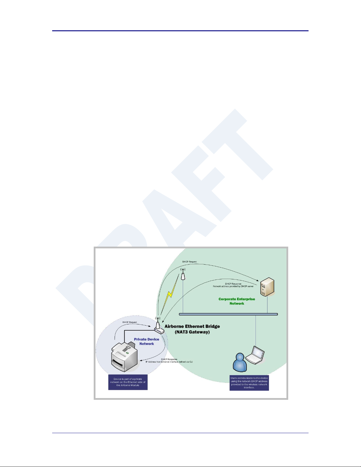
AirborneDirect™ Users Guide Quatech, Inc.
23.0 Configuring Ethernet Adapter
The ABDG-ET-DP5XX/IN5XXX devices are shipped preconfigured for use as an Ethernet
adapter. All that is required is configuration of the WLAN parameters and security
protocols; however the following section will cover the full configuration of an Ethernet
Device to aid in the installation and deployment of the units.
The Airborne Ethernet adapter is a fully functional NAT Level 3 router, supporting a public
IP address for the WLAN interface and a private network for the attached devices on the
Ethernet interface.
Network Address Translation (NAT) is the process of modifying network address
information in datagram packet headers while in transit across a traffic routing device for
the purpose of remapping a given address space into another. In the case of a NAT Level
3 device, the modification of the packet headers provides for a translation between a
single public IP address (that of the WLAN interface) and the IP address of the devices
on the private network (Ethernet interface).
The Airborne Adapter WLAN interface is considered the public address and will be the
point of contact on the target network (see Figure 20). This interface supports all the
wireless and network authentication requirements including support for WPA2-Enterpise.
It can acquire an IP address through both DHCP or user configured static IP.
Configuration, association and authentication are handled entirely by the Airborne Bridge
and require no interaction from the wired host on the private network.
Figure 20 - Ethernet Bridge Functionality
100-8510-110 2/21/2011 81
Page 82

Quatech, Inc. AirborneDirect™ User Manual
The Private network is the wired interface provided by the bridge. This interface includes
a DHCP server and supports dynamic and static IP address assignment. This means any
Ethernet client supporting DHCP can be connected to the wired interface without any
configuration changes. The private network host can communicate with the Airborne
Adapter using the bridges Ethernet IP address on the private network.
The Airborne Ethernet Adapter supports NAT Level 3 and as such provides the following
advantages over the more traditional bridge functionality:
A single network IP address on the public network. This simplifies management
of the devices on the network.
A single point of authentication. The Airborne device handles authentication for
the public network, this means a single point of contact for all security interaction,
simplifying deployment for the network.
Zero security footprint on the private network host.
Support for DHCP and static IP on the private network. This capability allows the
host to be shipped without any configuration changes.
Port forwarding. Allows you to decide if web page, telnet or FTP access should
be forwarded to the private network or handled by the Airborne Bridge.
Plug-n-Play. In most cases all that is required for full functionality is configuration
of the wireless interface for the target network. This can be done before
deployment to minimize deployment time and complexity.
23.1 Public Network Interface
The public network interface is the Airborne Adapter WLAN port. This interface
must be configured to associate and authenticate with the target network.
Configuration of this interface is covered in section 17.0.
The public address becomes the target address for all accesses to the host
device connected to the private network. In the example shown in Figure 21, any
device on the public network wanting to communicate with the Host device (IP:
192.168.2.100), would use the IP address 123.45.67.89, the Airborne Ethernet
Adapter will forward all traffic to the private address 192.168.2.100.
The network infrastructure will show the MAC and IP address of the Airborne
Adapter WLAN interface as the network presence, as a consequence of this all
traffic will be identified as being from or to this address.
82 2/21/2011 100-8510-110
Page 83
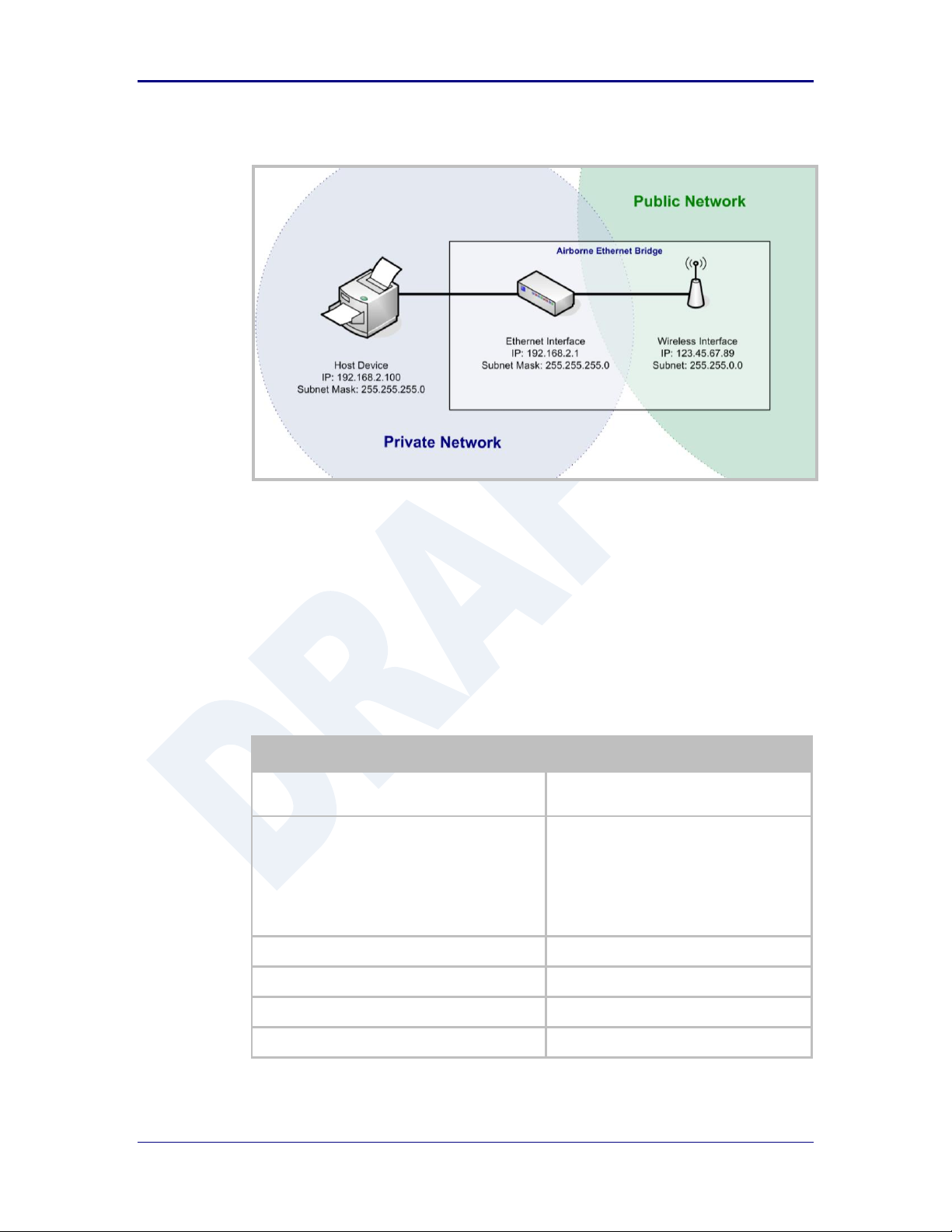
AirborneDirect™ Users Guide Quatech, Inc.
Step
Description
Navigation Bar
Select Configuration
You will see a group of fields under the
banner of WLAN Parameters.
Feature Link
Select Ethernet Settings
The wireless interface and security must be
configured before configuring the Ethernet
settings.
A page showing the range of Ethernet
options and fields, setting the mode of
operation for the Ethernet interface is done
in this page.
Select DHCP Server Enabled
Select Enable from drop down menu.
Select Ethernet Role
Select Router from the drop down menu.
Press Commit [Button]
Saves changes to the device.
Press Reload [Button]
Reloads the Ethernet Settings page.
Figure 21 - Airborne Ethernet Bridge IP Configuration
The public network interface supports the Airborne™ discovery protocol and will
respond to discovery requests issued on the public network.
23.2 Private Network Interface
The private network interface is on the Ethernet port of the Airborne Adapter. The
interface supports multiple Ethernet clients with either a static or DHCP sourced
IP addresses. The configuration of this interface is covered in Table 45 and Table
46.
Table 45 - Ethernet Adapter interface Configuration - DHCP
100-8510-110 2/21/2011 83
Page 84

Quatech, Inc. AirborneDirect™ User Manual
Step
Description
Feature Link
Select Network Settings
The wireless interface and security must be
configured before configuring the network
settings.
A page showing the range of network
options and fields, for both the WLAN and
Ethernet interfaces, is displayed.
Select Ethernet Static IP Address
Enter a valid IP address. This address will be
the first IP address leased. If more than one
is leased they will increment from this
address.
The subnet of the address must be different
than the WLAN interface subnet.
The address must be in the format:
XXX.XXX.XXX.XXX
This is also the default address all incoming
traffic on the WLAN interface is routed to.
Select Ethernet Subnet Mask
Enter the subnet mask for the private
network.
The mask must be in the format:
XXX.XXX.XXX.XXX
Select Ethernet Gateway IP Address
Enter a valid Gateway IP address. This is the
Static IP address of the Ethernet interface on
the private network. This must be in the
same subnet as the Ethernet Static IP
Address.
The address must be in the format:
XXX.XXX.XXX.XXX
Press Commit [Button]
Saves changes to the device.
Optional
Press Reload [Button]
Reloads the Network Settings page. Select
this is you have further configuration options
to change.
Optional
Press Restart [Button]
Restarts the device. After the device as
rebooted it will attempt to authenticate to
the configured network. As long as the
network is in range the wireless interface will
connect.
The Ethernet interface will have leased IP
addresses to the Ethernet clients and the
Ethernet interface would have taken the
Ethernet Gateway IP Address. Access to
the public network from the private network
is now possible.
Step
Description
Navigation Bar
Select Configuration
You will see a group of fields under the
banner of WLAN Parameters.
84 2/21/2011 100-8510-110
Unless your public network is using the default 192.168.2.XX subnet you should
not change the Ethernet parameters.
Table 46 - Ethernet Adapter interface Configuration - Static IP
Page 85

AirborneDirect™ Users Guide Quatech, Inc.
Step
Description
Feature Link
Select Ethernet Settings
The wireless interface and security must be
configured before configuring the Ethernet
settings.
A page showing the range of Ethernet
options and fields, setting the mode of
operation for the Ethernet interface is done
in this page.
Select DHCP Server Enabled
Select Disable from drop down menu.
Select Ethernet Role
Select Router from the drop down menu.
Press Commit [Button]
Saves changes to the device.
Press Reload [Button]
Reloads the Ethernet Settings page.
Feature Link
Select Network Settings
The wireless interface and security must be
configured before configuring the network
settings.
A page showing the range of network
options and fields, for both the WLAN and
Ethernet interfaces, is displayed.
Select Ethernet Static IP Address
Enter the static IP address of the Ethernet
client attached to the devices Ethernet port.
The subnet of the address must be different
than the WLAN interface subnet.
The address must be in the format:
XXX.XXX.XXX.XXX
This is also the default address all incoming
traffic on the WLAN interface is routed to.
Select Ethernet Subnet Mask
Enter the subnet mask for the private
network that matches the subnet mask on
the Ethernet client.
The mask must be in the format:
XXX.XXX.XXX.XXX
Select Ethernet Gateway IP Address
Enter a valid Gateway IP address. This is the
Static IP address of the Ethernet interface on
the private network. This must be in the
same subnet as the Ethernet Static IP
Address, but a different address.
The address must be in the format:
XXX.XXX.XXX.XXX
This address should be entered into the
Gateway parameter for the Ethernet clients
on the private network.
Press Commit [Button]
Saves changes to the device.
Optional
Press Reload [Button]
Reloads the Network Settings page. Select
this is you have further configuration options
to change.
100-8510-110 2/21/2011 85
Page 86

Quatech, Inc. AirborneDirect™ User Manual
Step
Description
Optional
Press Restart [Button]
Restarts the device. After the device as
rebooted it will attempt to authenticate to
the configured network. As long as the
network is in range the wireless interface will
connect.
Access to the public network from the
private network is now possible.
The subnet for the private network IP addresses (Ethernet Client and Gateway) and
public IP address (WLAN), obtained by the module via the wireless interface, MUST
NOT be the same.
Failure to observe this requirement will result in unpredictable behavior of the
adapter.
The private network supports the Airborne™ discovery protocol (UDAP) and will
respond to discovery requests.
When attempting to make an out-bound connection to a device on the public
network, the public network IP address of the device should be used e.g. In
Figure 21 the client with address 192.168.2.100 wants to connect to an FTP
server, with the address of 123.45.67.99, on the public network to perform a
firmware download. The FTP address that would be used in the
Configuration/Advanced Settings FTP Server Address or Name would be
123.45.67.99. Note that this is not within the subnet of the Ethernet client,
however the NAT router will do the necessary address translations and packet
header manipulations to ensure the out-bound and in-bound connections are
maintained.
Any traffic between the Airborne Ethernet Adapter’s Ethernet interface and
Ethernet client, on the private network, will not be broadcast on the public
network unless it is directed at the public network.
For most users there will be no modification of the private network settings
needed and if the target Ethernet client uses DHCP to obtain an IP address, no
change in configuration will be required either.
86 2/21/2011 100-8510-110
Page 87

AirborneDirect™ Users Guide Quatech, Inc.
24.0 Web Page Overview
The following section highlights the contents of each web page and provides a reference
to the associated CLI command. For further explanation of each of the fields please refer
to the referenced command in the table (See Airborne Enterprise Command Line
Reference Manual).
100-8510-110 2/21/2011 87
Page 88

Quatech, Inc. AirborneDirect™ User Manual
URL
/Status/Module Status
Description
The home page when authenticated to the Airborne device, this page provides important information
about the device’s firmware version, wireless connection status and wireless interface network
configuration.
Field
CLI Command
Displayed Page
wl-info
Module Status
88 2/21/2011 100-8510-110
Page 89

AirborneDirect™ Users Guide Quatech, Inc.
URL
/Status/Ethernet Status
Description
Provides important information about the device’s firmware version, Ethernet connection status and
Ethernet interface network configuration.
Field
CLI Command
Displayed Page
eth-info
Ethernet Status
100-8510-110 2/21/2011 89
Page 90

Quatech, Inc. AirborneDirect™ User Manual
URL
/Status/Ethernet DHCP Clients
Description
Displays the IP address issued by the DHCP server to specific MAC addresses.
Field
CLI Command
Displayed Page
eth-dhcp-clients
Ethernet DHCP Clients
90 2/21/2011 100-8510-110
Page 91

AirborneDirect™ Users Guide Quatech, Inc.
URL
/Status/Radio Statistics
Description
Provides information about the packet transmit and receive performance of the wireless interface.
Field
CLI Command
Displayed Page
stats <blank> or radio
Radio Statistics
100-8510-110 2/21/2011 91
Page 92
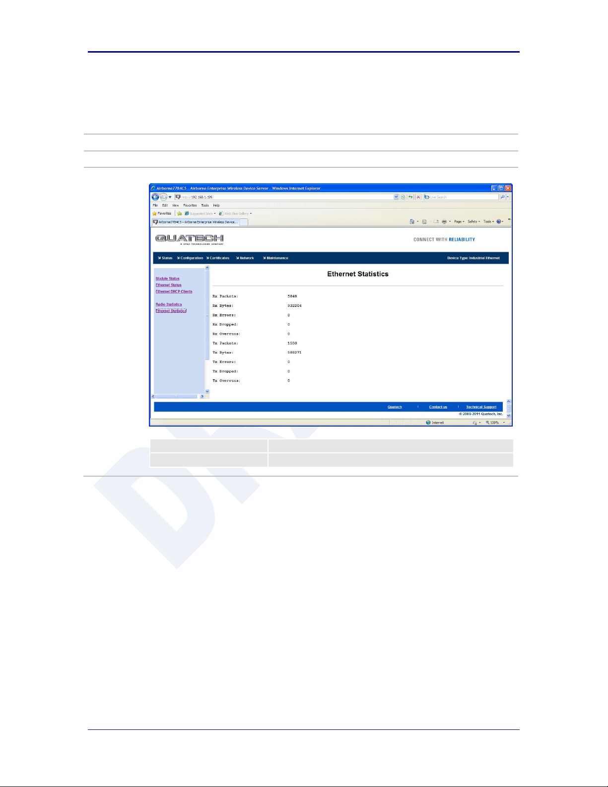
Quatech, Inc. AirborneDirect™ User Manual
URL
/Status/Ethernet Statistics
Description
Provides information about the packet transmit and receive performance of the Ethernet interface.
Field
CLI Command
Displayed Page
stats ethernet
Ethernet Statistics
92 2/21/2011 100-8510-110
Page 93
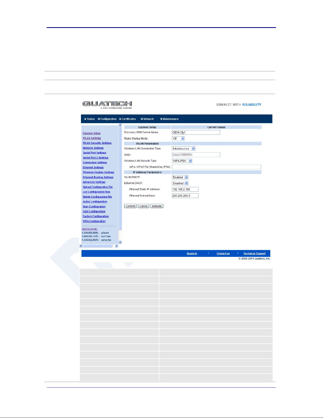
AirborneDirect™ Users Guide Quatech, Inc.
URL
/Configuration/Express Setup
Description
A page that provides a simplified configuration option set in a single page. Is the default home page
when configuring the device for the first time or after a factory reset has been performed.
Field
CLI Command
Discovery OEM Device Name
name-oem
Radio Startup Mode
radio-on, radio-off
Wireless LAN Connection Type
wl-type
SSID
wl-ssid
Wireless LAN Security Type
wl-security
WEP Key 1
wl-key-1
WPA/WPA2Pre Shared Key (PSK)
pw-wpa-psk
LEAP User Name
user-leap
LEAP Password
pw-leap
PEAP Identity
eap-ident
PEAP PAssword
eap-password
WLAN DHCP
wl-dhcp
Ethernet DHCP
eth-dhcp
WLAN Static IP Address
wl-ip
Express Setup
100-8510-110 2/21/2011 93
Page 94

Quatech, Inc. AirborneDirect™ User Manual
WLAN Subnet Mask
wl-subnet
Ethernet Static IP Address
eth-ip
Ethernet Subnet Mask
eth-subnet
94 2/21/2011 100-8510-110
Page 95

AirborneDirect™ Users Guide Quatech, Inc.
URL
/Configuration/WLAN Settings
Description
Configures the wireless interface settings including network name and type.
Field
CLI Command
Radio Startup Mode
radio-on, radio-off
Wireless LAN Connection Type
wl-type
Wireless LAN Channel
wl-chan
SSID
wl-ssid
Maximum Wireless Data Rate
wl-rate
Use Fixed Data Rate
wl-fixed-rate
Wireless LAN Region
wl-region
WLAN Settings
100-8510-110 2/21/2011 95
Page 96

Quatech, Inc. AirborneDirect™ User Manual
URL
/Configuration/WLAN Security Settings
Description
Configures the security settings for the target network.
Field
CLI Command
Wireless LAN Security Type
wl-security
Authentication Type
wl-auth
LEAP User Name
user-leap
LEAP Password
pw-leap
Default WEP Key
wl-def-key
WEP Key 1 - 4
wl-key-1, wl-key-2, wl-key-3, wl-key-4
WPA Protocol Version
wl-wpa-format
WPA/WPA2 Pre Shared Key (PSK)
pw-wpa-psk
WLAN Security Settings
96 2/21/2011 100-8510-110
Page 97

AirborneDirect™ Users Guide Quatech, Inc.
EAP Identity
eap-ident
EAP Password
eap-password
EAP Anonymous Identity
eap-anon-ident
EAP Phase String 1
eap-phase1
EAP Phase String 2
eap-phase2
EAP Subject Match String
subject-match
EAP Subject Match 2 String
subject-match2
EAP Alternate Subject Match String
alt-subject-match
EAP Alternate Subject Match 2 String
alt-subject-match2
CA Certificate File Name
ca-cert-filename
CA Certificate 2 File Name
ca-cert2-filename
Client Certificate File Name
client-cert-filename
Client Certificate 2 File Name
client-cert2-filename
Private Key File Name
priv-key-filename
Private Key File Password
priv-key-password
Private Key 2 File Name
priv-key2-filename
Private Key File 2 Password
priv-key2-password
DH Parameter File Name
dh-parm-filename
DH Parameter 2 File Name
dh-parm2-filename
EAP-FAST Provisioning Type
eap-fast-provisioning
Maximum Number of EAP-FAST Servers
eap-fast-max-pac-list
100-8510-110 2/21/2011 97
Page 98

Quatech, Inc. AirborneDirect™ User Manual
URL
/Configuration/Network Settings
Description
Configures the wireless and Ethernet interface network settings including DHCP, static IP and fall back
configurations.
Field
CLI Command
DNS Server1/2 IP Address
dns-server1, dns-server2
WINS Server1/2 IP Address
wins-server1, wins-server2
WLAN DHCP
wl-dhcp
WLAN DHCP Client Name
wl-dhcp-client
WLAN DHCP Request Retransmission Mode
wl-dhcp-mode
WLAN DHCP Request Retransmission Interval
wl-dhcp-interval
WLAN DHCP Acquire Limit
wl-dhcp-acqlimit
WLAN Static IP Address
wl-ip
Network Settings
98 2/21/2011 100-8510-110
Page 99

AirborneDirect™ Users Guide Quatech, Inc.
WLAN Subnet Mask
wl-subnet
WLAN Gateway IP Address
wl-gateway
WLAN DHCP Fallback
wl-dhcp-fb
WLAN Fallback to Last DHCP IP Address
wl-dhcp-fbauto
Save Last WLAN DHCP IP Address as Fallback IP Addresss
wl-dhcp-fbper
WLAN Fallback IP Address
wl-dhcp-fbip
WLAN Fallback Gateway IP Address
wl-dhcp-fbgateway
WLAN Fallback Subnet Mask
wl-dhcp-fbsubnet
Ethernet DHCP
eth-dhcp
Ethernet DHCP Client Name
eth-dhcp-client
Ethernet DHCP Request Retransmission Mode
eth-dhcp-mode
Ethernet DHCP Request Retransmission Interval
eth-dhcp-interval
Ethernet DHCP Acquire Limit
eth-dhcp-acqlimit
Ethernet Static IP Address
eth-ip
Ethernet Subnet Mask
eth-subnet
Ethernet Gateway IP Address
eth-gateway
Ethernet DHCP Fallback
eth-dhcp-fb
Ethernet Fallback to Last DHCP IP Address
eth-dhcp-fbauto
Save Last Ethernet DHCP IP Address as Fallback IP Addresss
eth-dhcp-fbper
Ethernet Fallback IP Address
eth-dhcp-fbip
Ethernet Fallback Gateway IP Address
eth-dhcp-fbgateway
Ethernet Fallback Subnet Mask
eth-dhcp-fbsubnet
100-8510-110 2/21/2011 99
Page 100

Quatech, Inc. AirborneDirect™ User Manual
URL
/Configuration/Serial Port Settings
Description
Configures the serial port settings on the primary serial port.
Field
CLI Command
Serial Port Bit Rate
bit-rate, parity-p1
Parity
parity, parity-p1
Data Bits
data-bits, data-bits-p1
Stop Bits
stop-bit, stop-bit-p1
Flow Control
flow, flow-p1
Serial Assert
serial-assert, serial-assert-p1
Input Buffer Flush Size
input-size, input-size-p1
Serial Escape Mode
esc-mode-serial, esc-mode-serial-p1
Escape String
esc-str, esc-str-p1
Serial CLI Default Mode
serial-default, serial-default-p1
Serial Interface Type
intf-type
Wireless LAN CLI Escape Mode
esc-mode-lan, esc-mode-lan-p1
Serial Port Settings
100 2/21/2011 100-8510-110
 Loading...