

Page 1

Thank you for purchasing “SmartCell 212 /112” product.
Quasar Communication Systems Ltd. and its distributors assume no
responsibility for any damage or loss resulting from the use of its products or
this user manual. Quasar Communication Systems Ltd and its distributors
assume no responsibility for any loss or claims by third parties, which may
arise through the use of its products.
Registration and Type Approval
Smartcell 212 /112 carries CE Certification, Australia AS/NZS3548
Corporate contacts
E-mail: sales@quasar.biz
Web address: www.quasar.biz
© Quasar Communication Systems Ltd. All rights reserved. Quasar, the
Quasar Logo, CelluLink and CellBox are registered trademarks of Quasar
Communication Systems Ltd. Other product and brand names may be
trademarks or registered trademarks of their respective owners.
September 2003
Page 2

Page 3

1. Introduction
1.1 Overview
The SmartCell 212 and 112 gateway enables direct connection of an
organization's internal telephony system to commercial cellular networks via
an already existing Private Branch Exchange (PBX) system.
The SmartCell 212 has a standard ISDN BRI “S0” interface on the Line side
and connects with 2 channels to any GSM cellular network to create a
cellular gateway. The SmartCell 112 is a single channel gateway. SmartCell
212/112 operates at 900MHz/1800MHz. The 212-1900 and 112-1900
models operate at 900MHz/1900MHz.
1.2 Packing List
for 212
Item Description Qty
1 SmartCell 212 unit 1
2 Power Supply 1
3 ISDN S Interface Cable (straight) 1
4 SYNC IN Cable (straight) 1
5 Antenna 2
6 Bag with Screws and Dowel Pins 1
7 Bracket 2
8 Installation Guide 1
for 112
Same list apart of one antenna and one bracket provided.
2
Page 4

2 Bags with Screws
& Dowel pins
SmartCell 212/112
SmartCell 212/112 unit
Cables
Power Cable
ISDN Interface Cable
SYNC IN Cable
Antenna
Drill Template
3
Page 5

2. Safety Precautions
Main voltages are present at specific points in this equipment. Some of the
parts can also have high operating temperatures. Non-observance of these
conditions and safety instructions can result in personal injury or in property
damage.
The Smartcell 212 system complies with the standard IGC 950. All
connected equipment must comply with the applicable safety standards:
EN 55022
IEC 1801-2/91
IEC 801-3
IEC 801-4
To avoid injury and prevent equipment damage, observe the following safety
precautions:
Do not ship equipment unless it is properly packed in its original wrapping
and shipping containers.
Do not connect the 212 or 112 to any power supply other than the one
provided with it.
Equipment service and maintenance should be done only by qualified
personnel.
4
Page 6
3. Product Description
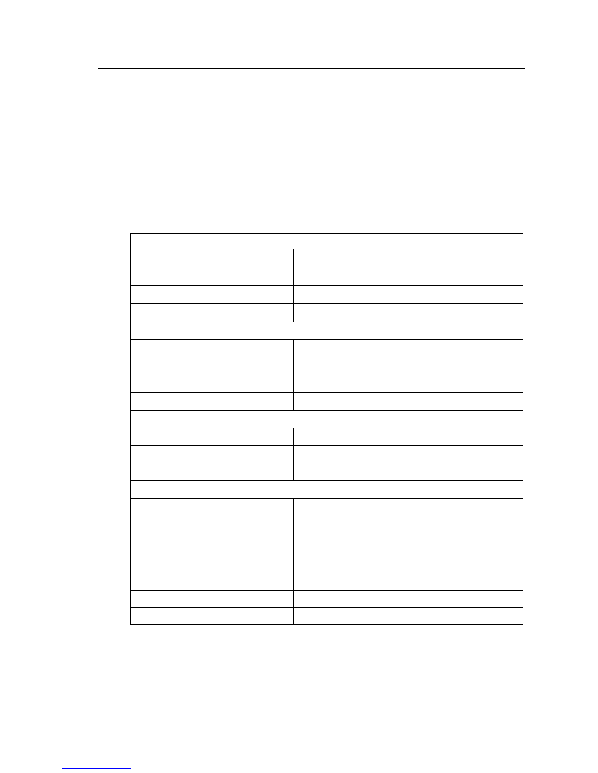
3.1 Technical Specifications*
Power supply
Supply voltage (secondary) 12V DC
Supply current 2 A max.
SmartCell 212/112
Operating temperature
Standards
0 ºC to 40 ºC
Full CE
ISDN specifications
Line interface BRI – S/T point reference (indoor only),
Type NT or partial TE.
Protocol Euro ISDN.
Connector type RJ-45
Data Port Specifications
Interface port/Connector type RS232
Protocol AT command compatible
Dial tone 400 Hz ± 1%
GSM channel specifications
Cellular interface Wavecom GSM module
Networks supported Dual band EGSM 900/1800 MHz for 212
or 900/1900 for 212-1900
Standards
Antenna
Full type approval according to GSM phase 2+
specifications.
Antenna gain Antenna gain – 2.5 0dB
Antenna connector FME or SMA
*Specifications are subject to changes without notice
5
Page 7
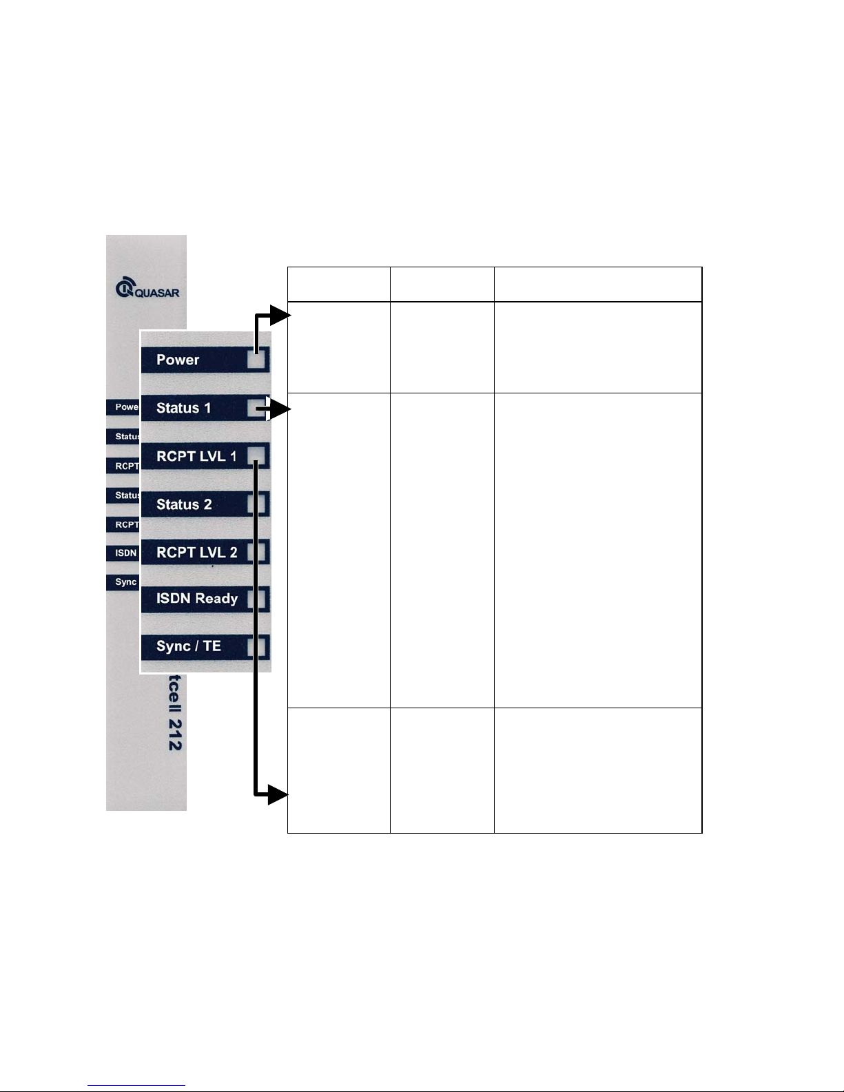
3.2 LED Indications
Led Description Operation
Power
Status 1
Indicates the
status of the
power
connection.
Indicates the
SmartCell
212
operational
status of
channel 1
On
–the SmartCell 112/212 is
powered on.
Off
–the SmartCell 112/212 is
powered off.
Off
–the channel is idle and no
calls are being handled.
On
–the channel is handling a
call.
Slow blinking
112/212 is initialising
following power up or is
being programmed.
Fast blinking
occurred in the PIN code
entry and the outgoing call
cannot be completed. The
PIN code must be disabled or
the default PIN code 1234
must be entered.
–the SmartCell
–an error has
6
RCPT.LVL 1
(Reception Level
Channel 1)
Indicates the
reception level
of the GSM
channel 1
Green
Orange
Red
Off
reception at all.
-High reception.
-Medium reception.
-Low reception
-Very low reception or no
Page 8

SmartCell 212/112
Led Description Operation
STATUS 2
RCPT.LVL 2
(Reception Level
Channel 2)
Indicates the
SmartCell
212
operational
status of
channel 2.
Indicates the
reception
level of the
GSM
channel 2
Off–
the channel is idle and no
calls are being handled.
On
–the channel is handling a
call.
Slow blinking
–the SmartCell
112/212 is initialising
following power up or is
being programmed.
Fast blinking
–an error has
occurred in the PIN code
entry and the outgoing call
cannot be completed. The
PIN code must be disabled or
the default PIN code 1234
must be entered.
Green
Orange
Red
Off
-High reception.
-Medium reception.
-Low reception.
-Very low reception or no
reception at all.
ISDN Ready
Sync/ TE
ISDN NT
interface
indicate the
ISDN NT
port physical
layer status.
ISDN TE
interface
indicates the
TE physical
layer status or
the Sync IN
status.
Off–
No ISDN NT Layer 1
connection.
On–
ISDN NT layer 1
connection established.
Off–
No ISDN TE Layer 1
connection or no Sync IN.
On–
ISDN TE layer 1
connection established or
Sync IN is active.
7
Page 9
4. SmartCell 212/112 Installation
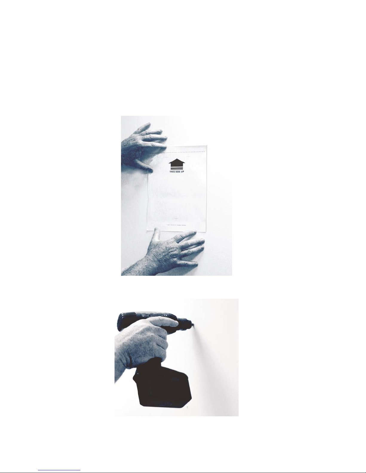
4.1 Installation Instructions
4.1.1 Locate template on the wall and mark screw location
4.1.2 Bore 3 holes.
8
Page 10

SmartCell 212/112
4.1.3 Insert 3 dowel pins.
4.1.4 Tighten the two upper screws. Leave a gap of 3mm minimum between
the screw head and the wall.
4.1.5 Mount the SmartCell 212/112 on the 2 screws.
9
Page 11
N
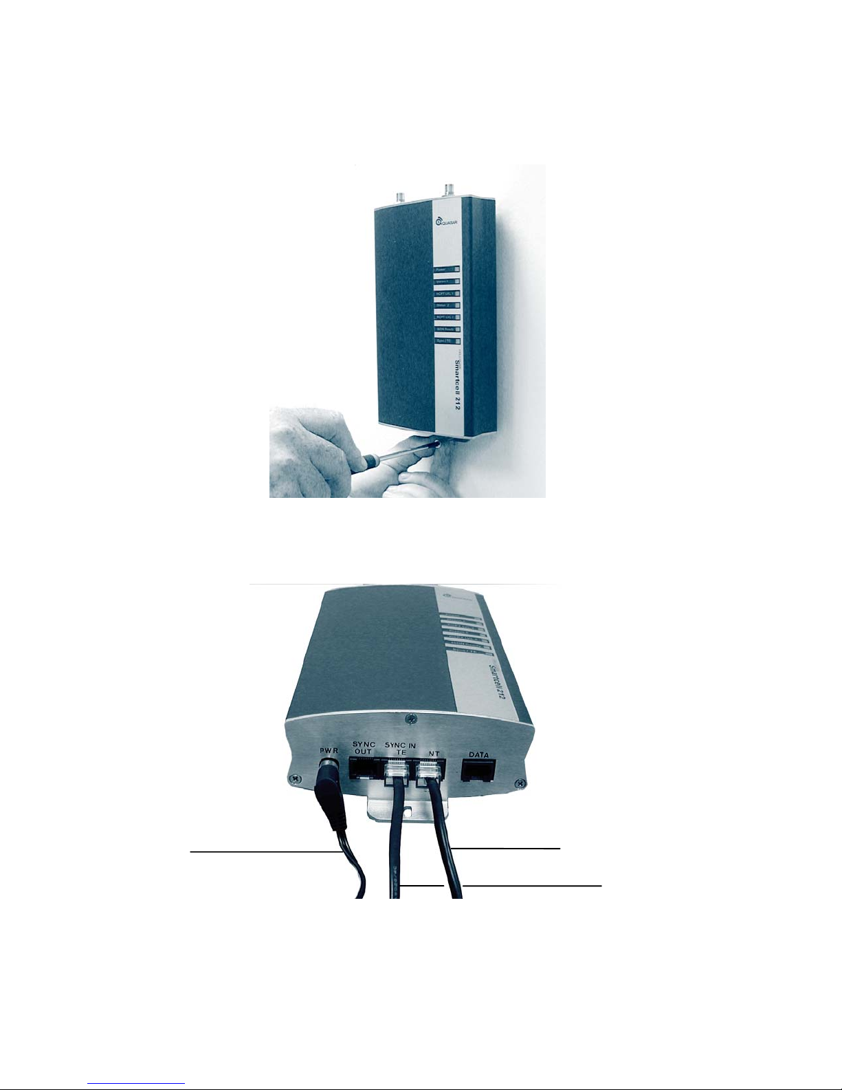
4.1.6 Tighten the lower screw.
4.1.7 Connect cables.
Power cable
T cable
SYNC IN cable
(only if necessary)
10
Page 12

SmartCell 212/112
4.1.8 Connect antennas.
Antenna
x2
Bracket
x2
11
Page 13

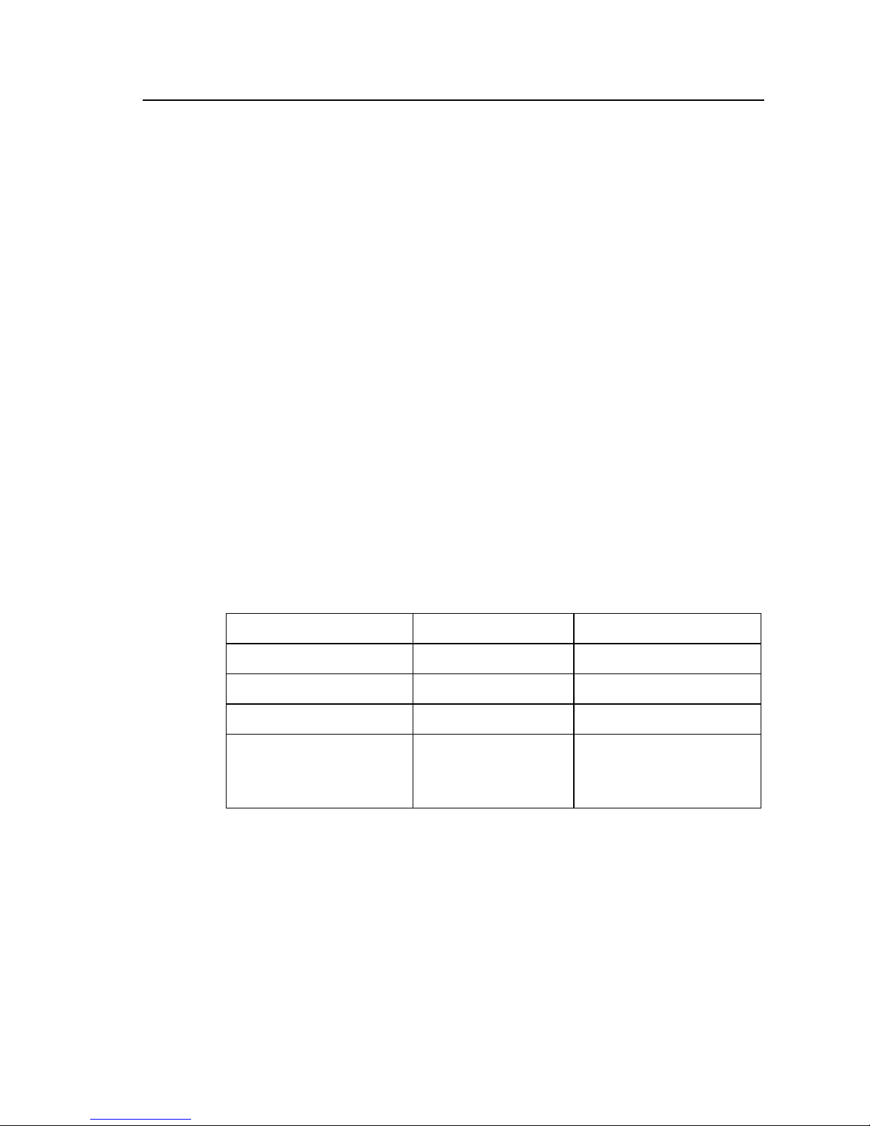
4.2 Configuration of the PABX
The PABX connected to a SmartCell device must be properly configured in
order to operate. The table below describes the configurations. For more
detailed information regarding the programming of the PABX, please contact
your PABX supplier.
PBX ISDN Interface Definitions
(for normal connection)
Description Comments
Define the ISDN interface (TE point
1
reference, point to point with TEI=0.)
Required
On LCR (Least Cost Routing) enabled
2
systems, set the CLI programmed to
identify cellular prefixes.
3 Use only the original ISDN cable (straight)
4.3 RJ-45 Connector Pin Layout
PIN # Function
1 NC (not connected) NC (not connected)
2 NC (not connected) NC (not connected)
3 RX (A) TX (A)
4 TX (A) RX (A)
5 TX (B) RX (B)
6 RX (B) TX (B)
7 NC (not connected) NC (not connected)
8 NC (not connected) NC (not connected)
NT Side TE Side
Optional SmartCell 212/112
becomes transparent to internal
callers.
Required to insure proper
operation.
In order to avoid damage, do not use the reserved pins.
12
Page 14
/
/
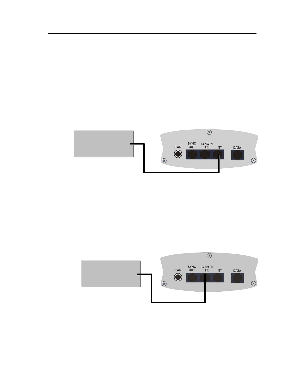
4.4 Cable Connections
4.4.1 Normal Connection
In normal connection, the 212/112 is used as the NT side and the
PABX as the TE side. The Sync (timing) is delivered from the 212/112
to the PABX over the ISDN cable. The Sync IN/TE port of the 212/112
is not used.
Note: If the PABX will not accept the 212/112 as a sync source, use the
configuration described in paragraph 4.4.3.
Note: ISDN Ready LED will be ON.
4.4.2 Partial TE mode
In this mode, the 212/112 is used as the TE side and the PABX is used
as the NT side of the ISDN connection. The Sync (timing) is delivered
from the PABX to the 212/112 over the same ISDN cable. To enable
this mode, use the QMS S/W to set the 212/112 to partial TE mode
(Layer 1 = TE, Layer 2 = TE, Layer 3 = NT).
Note: Sync IN/TE LED will be ON.
PABX
PABX
TE
NT
SmartCell 212/112
212
112
212
112
13
Page 15
/
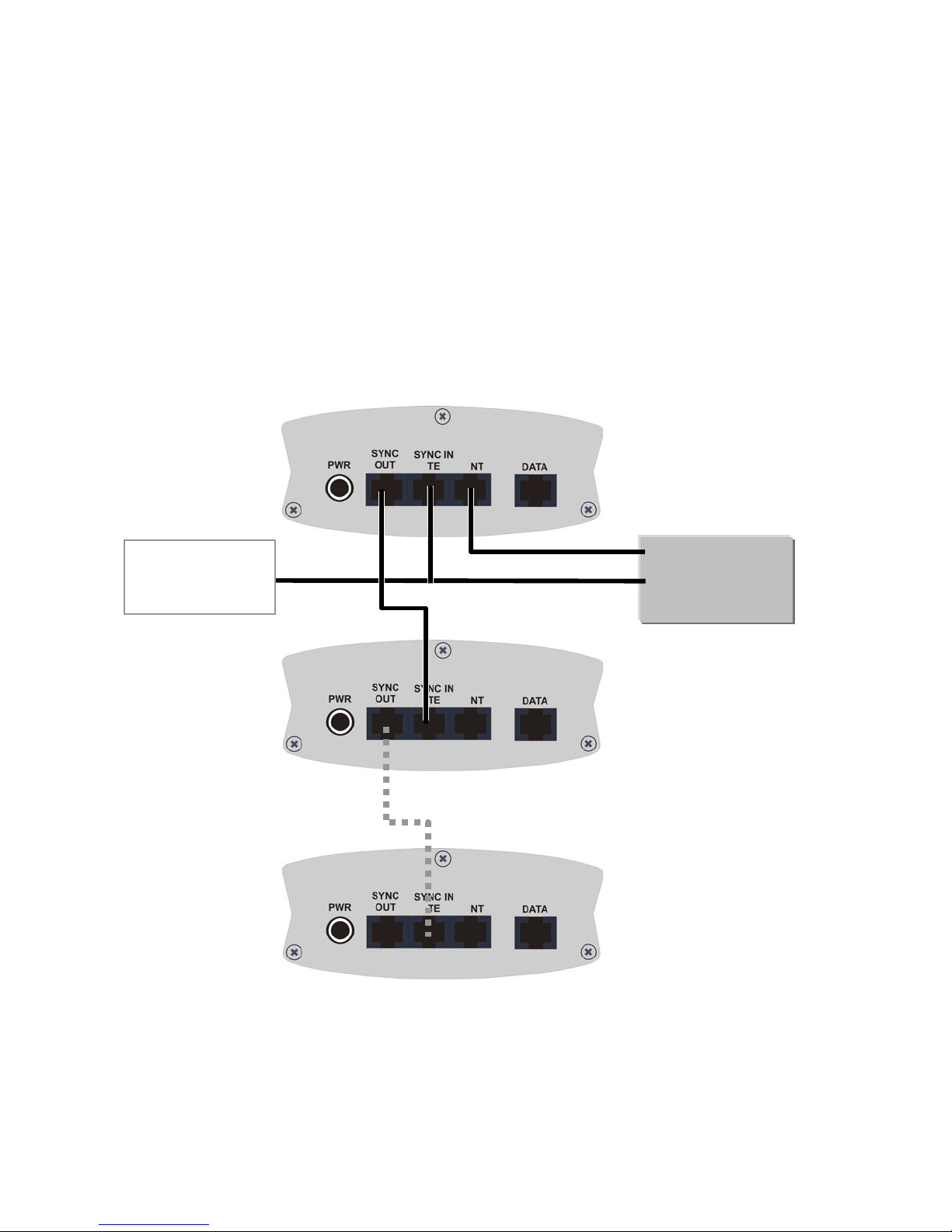
4.4.3 External Sync mode
In this mode, the PABX is used as the TE side and the 212/112 is used
as the NT side of the ISDN connection. However, the Sync (timing) is
delivered from the PABX to the 212/112 over a second cable (a straight
RJ-45 cable, provided with 212/112). This cable connects to any NT
port of the PABX, without interrupting the traffic. If more than one
212/112 need to be connected to the PABX - a chain connection can be
used such that the first 212/112 provides timing to the second, the
second 212/112 to the third and so on.
Other ISDN
telephones may be
connected here
212
112
TE
NT
TE
PABX
14
Page 16
4.5 Getting Started
4.5.1 After making all connections and installing the SIM cards, make sure
the POWER LED is lit. If it is not, make sure that the power supply is
properly connected to the unit and to the AC mains.
4.5.2 During the first few seconds after powering the unit, the STATUS LED
will start blinking, indicating unit initialisation. Once the SIM cards
have been registered and are operational, the STATUS LEDs will stop
blinking.
4.5.3 Verify that the RCPT. LVL LED is green, indicating high reception
level. To improve the reception level:
Move the antenna to a better location.
•
SmartCell 212/112
Place the antenna on a metal plate larger than 20X20cm.
•
Reception Level Indication
RCPT. LVL LED
Green High reception
Orange Medium reception
Red Low reception
Off
Reception Level Reception Level
-75dBm to – 51dBm
-87dBm to –77dBm
-101dBm to –89dBm
Very low
reception or no
reception at all
less than –103dBm
15
 Loading...