

Page 1

8VHU¶V*XLGH8VHU¶V*XLGH8VHU¶V*XLGH8VHU¶V*XLGH8VHU¶V*XLGH
4XDQWXP7&(
4XDQWXP7&(
7&(
%
Page 2

Quantum TC2201E User’s Guide, 81-81447-01 B01, October 2005, Made in USA.
Quantum Corporation provides this publication “as is” without warranty of any kind, either express or
implied, including but not limited to the implied warranties of merchantability or fitness for a particular
purpose. Quantum Corporation may revise this publication from time to time without notice.
COPYRIGHT STAT EMENTS
Copyright 2005 by Quantum Corporation. All rights reserved.
Your right to copy this manual is limited by copyright law. Making copies or adaptations without prior
written authorization of Quantum Corporation is prohibited by law and constitutes a punishable violation of
the law.
TRADEMARK STATEMENT
DLT, SDLT, DLTtape III, DLTtape IV and Super DLTtape I are all trademarks of Quantum Corporation.
Other trademarks may be mentioned herein which belong to other companies.
Page 3

Contents
Preface xvii
Chapter 1 Introduction 1
External Features ........................................................................................ 1
Operation Indicators.......................................................................................... 2
How the TC2201E Works..................................................................................3
Processing SCSI Information............................................................................ 4
LAN-free Backup and Restore ......................................................................... 6
TC2201E Features............................................................................................... 6
iSCSI Features ............................................................................................ 6
SCSI Bus Features...................................................................................... 7
Management Features............................................................................... 7
TC2201E Benefits................................................................................................ 7
Enterprise Class Performance................................................................... 8
Ease of Use to Reduce SAN Management Costs and Complexity...... 8
Add Intelligence to SCSI Storage..............................................................8
Industry Leading Inter Operability.......................................................... 9
Quantum TC2201E User’s Guide iii
Page 4

Contents
TC2201E Specifications......................................................................................9
Physical Specifications................................................................................9
Physical Dimensions...................................................................................9
Operating Environment .............................................................................9
Non-operating Environment...................................................................10
Power ..........................................................................................................10
Chapter 2 Getting Started 11
Location .............................................................................................................12
Unpacking the Box ...........................................................................................12
Mounting the TC2201E on a Desktop............................................................12
Mounting the TC2201E in a Rack...................................................................13
Required Tools...........................................................................................13
Installing the TC2201E With Ear Brackets.............................................13
Interfaces and Connections.............................................................................17
iSCSI Connections .....................................................................................18
SCSI Connection........................................................................................19
Ethernet Management Connection.........................................................22
RS-232 Serial Management Connection.................................................22
Setting Up Serial Port Communications................................................23
Connecting the Power Cable ...................................................................24
Configuring the TC2201E................................................................................25
Configuring the TC2201E using the Visual Manager ..........................25
Configuring the TC2201D Using the Command Line Interface......... 27
Save Backup Version of Configuration.........................................................28
Advanced Configuration Options .................................................................29
iSCSI Configuration ..................................................................................29
SCSI Configuration ...................................................................................30
Chapter 3 Quantum Visual Manager 31
Accessing Visual Manager..............................................................................32
Making Changes via Visual Manager ...........................................................34
iv Quantum TC2201E User’s Guide
Page 5

Contents
Main Menu........................................................................................................ 36
Main Menu
Main Menu
Main Menu
Main Menu
Main Menu
Main Menu
Main Menu
Main Menu
Main Menu
Main Menu
Main Menu
Main Menu
Main Menu
Main Menu
Main Menu > Utilities
Main Menu
Main Menu
Traces................................................................................................... 74
Main Menu
Main Menu > Utilities
Main Menu
Main Menu
Main Menu
Main Menu
Main Menu
Main Menu
Main Menu
> System ............................................................................... 36
> System > Serial Port Settings ......................................... 38
> System > iSCSI Settings..................................................39
> System > iSNS Settings................................................... 42
> System > User Settings ................................................... 44
> System > Real Time Clock Configuration ................... 46
> System > Factory Settings Reset.................................... 47
> Ethernet............................................................................. 49
> SCSI Bus............................................................................54
> SCSI Bus > Buffered Tape Writes..................................59
> Discovery.......................................................................... 61
> iSCSI Mapping ................................................................. 62
> Statistics ............................................................................ 67
> Utilities..............................................................................68
> FTP Utility...................................................... 69
> Utilities > Trace Settings ................................................ 72
> Utilities > Current TracesPrevious TracesLast Assert
> Utilities > Clear Current Traces .................................... 76
> Clear Assert Traces ....................................... 77
> Utilities > Event Log Settings ........................................78
> Utilities > Event Log ....................................................... 80
> Utilities > Clear Event Log............................................. 81
> Utilities > SCSI Command Tracking ............................ 82
> Features............................................................................. 84
> Report................................................................................ 85
> Reboot ............................................................................... 86
Chapter 4 Troubleshooting 87
Indicators...........................................................................................................87
Quantum TC2201E User’s Guide v
Page 6

Contents
Basic Verification..............................................................................................89
Serial Port Problems..................................................................................89
Verify SCSI Bus Configuration................................................................89
Verify iSCSI Connection...........................................................................90
Verify SCSI Devices in Windows NT.....................................................90
Verify Configuration.................................................................................90
Verify Mapping .........................................................................................91
Verify Devices............................................................................................91
Verify Host Configuration.......................................................................91
Verify HBA Device Driver Information.................................................91
Customer Support.....................................................................................91
Appendix A 3-Pin to DB-9 Serial Pin Assignments 93
RJ-45 Ethernet Pin Assignments.....................................................................95
Appendix B Inband SCSI-3 Commands 97
General Commands .........................................................................................98
Report LUNs Command ..........................................................................98
Inquiry Command.....................................................................................99
Vendor Unique Commands..........................................................................102
Appendix C Using the Command Line Interface 103
Power Up Messages.......................................................................................104
Perform Configuration ..................................................................................106
User Settings Configuration ..................................................................107
Baud Rate Configuration .......................................................................107
Ethernet Configuration...........................................................................108
iSCSI Configuration ................................................................................112
Parallel SCSI Configuration...................................................................116
Parallel SCSI Buffered Tape Write Configuration Menu ..................120
Device Mapping ......................................................................................122
Trace and Event Settings Configuration..............................................136
Real-Time Clock Configuration ............................................................144
Save Configuration .................................................................................144
Restore Last Saved Configuration ........................................................144
Reset and Save Configuration to Factory Defaults ............................145
vi Quantum TC2201E User’s Guide
Page 7

Contents
System Utilities............................................................................................... 145
System Statistics......................................................................................146
Event Log .................................................................................................148
View Report............................................................................................. 149
SCSI Command Tracking ......................................................................150
Display Trace and Assertion History.......................................................... 151
Reboot.............................................................................................................. 152
Advanced Software Licensed Features....................................................... 152
Download a New Revision of the Firmware .............................................153
Appendix D Using the FTP Interface 155
Backup/Restore Configuration Settings .................................................... 155
Configuration Backup Procedure......................................................... 155
Configuration Restore Procedure......................................................... 157
Get a Copy of Trace Buffer or Event Log ................................................... 158
Update Firmware........................................................................................... 159
Appendix E How to Change Block Sizes 161
Procedure A: EMC Legato NetWorker.......................................................161
Procedure B: Veritas NetBackup ................................................................ 163
Procedure C: Veritas Backup Exec .............................................................. 164
Procedure D: CA Brightstor ARCserve ...................................................... 165
Procedure E: Bakbone NetVault ..................................................................166
Procedure F: HP Data Protector................................................................... 167
Procedure G: CommVault Galaxy...............................................................169
Glossary 173
Quantum TC2201E User’s Guide vii
Page 8

Contents
viii Quantum TC2201E User’s Guide
Page 9

Figures
Figure 1 Front Panel ....................................................................................1
Figure 2 Back Panel...................................................................................... 2
Figure 3 TC2201E LEDs .............................................................................. 3
Figure 4 Example Configuration ............................................................... 4
Figure 5 Information Processing................................................................ 5
Figure 6 Flow of data and responses ........................................................ 5
Figure 7 LAN-free backup..........................................................................6
Figure 8 Installing Cage Nuts ................................................................. 14
Figure 9 Locating front of ear brackets...................................................14
Figure 10 Attaching the Ear Brackets........................................................ 15
Figure 11 Mounting at Front of Rack ........................................................ 16
Figure 12 Mounting at Back of the Rack...................................................17
Figure 13 Port locations............................................................................... 18
Figure 14 WWN/MAC ID label ................................................................ 18
Figure 15 iSCSI ports ................................................................................... 19
Figure 16 High Density SCSI Cables......................................................... 20
Figure 17 TC2201E SCSI connection ......................................................... 21
Quantum TC2201E User’s Guide ix
Page 10

Figures
Figure 18 TC2201E Ethernet port...............................................................22
Figure 19 TC2201E Serial Port ....................................................................23
Figure 20 TC2201E Power Switch and Connector...................................25
Figure 21 Visual Manager Home Page......................................................35
Figure 22 TC2201E Image............................................................................35
Figure 23 Main Menu...................................................................................36
Figure 24 System Page.................................................................................37
Figure 25 Serial port settings page.............................................................38
Figure 26 iSCSI Settings Page .....................................................................39
Figure 27 iSCSI Authentication Settings Page .........................................40
Figure 28 iSNS Settings Page ......................................................................42
Figure 29 User settings page.......................................................................44
Figure 30 Real Time Clock Configuration Page.......................................46
Figure 31 Factory Settings Reset Page.......................................................48
Figure 32 Ethernet Settings Page................................................................49
Figure 33 Host name Page ..........................................................................50
Figure 34 Ethernet Port Configuration Page ............................................51
Figure 35 Ethernet Overrides Settings Page.............................................53
Figure 36 SCSI Bus Page..............................................................................54
Figure 37 SCSI bus Configuration Page ....................................................55
Figure 38 SCSI Overrides Settings Page....................................................56
Figure 39 SCSI target Overrides Settings Page ........................................57
Figure 40 SCSI Bus Page..............................................................................59
Figure 41 Discovery Page............................................................................61
Figure 42 iSCSI Mapping Page...................................................................62
Figure 43 Select Host Page..........................................................................64
Figure 44 Select Current Map Page ...........................................................65
Figure 45 Statistics Page ..............................................................................67
Figure 46 Utilities page................................................................................68
x Quantum TC2201E User’s Guide
Page 11

Figures
Figure 47 FTP utility page .......................................................................... 70
Figure 48 Trace settings page..................................................................... 72
Figure 49 Advanced trace settings page................................................... 73
Figure 50 Current TracesPage.................................................................... 75
Figure 51 Clear Current Trace Buffer Page .............................................. 76
Figure 52 Clear Assertion Trace Buffer Page........................................... 77
Figure 53 Event Log Settings Page ............................................................ 78
Figure 54 Display Event Log Page ............................................................ 80
Figure 55 Clear Event Log Page................................................................. 81
Figure 56 SCSI Command Tracking.......................................................... 82
Figure 57 Features Page .............................................................................. 84
Figure 58 Report page ................................................................................. 85
Figure 59 Reboot Page................................................................................. 86
Figure 60 TC2201E LEDs ............................................................................ 88
Figure 61 Clear all Entries from Current Map.......................................129
Figure 62 Registry Editor .......................................................................... 163
Figure 63 Veritas Backup Exec.................................................................165
Figure 64 Netvault Device Management................................................ 167
Figure 65 HP Data Protector (Advanced Options) ............................... 169
Figure 66 CommVault Galaxy .................................................................170
Figure 67 CommVault Galaxy (Advanced Tab)....................................171
Quantum TC2201E User’s Guide xi
Page 12

Figures
xii Quantum TC2201E User’s Guide
Page 13

Tables
Table 1 RJ-11 Pin Assignments............................................................... 93
Table 2 Corresponding Pin Outs of DB-9 Connector.......................... 94
Table 3 RJ- 45 pin Assignments.............................................................. 95
Table 4 Format of Report LUNs Command......................................... 98
Table 5 Report LUNs Parameter List .................................................... 99
Table 6 Format of LUN Inquiry Command ......................................... 99
Table 7 Format of EVPD Page 0x80..................................................... 100
Table 8 TC2201E LUN Inquiry Data.................................................... 100
Table 9 Vendor Unique Commands................................................... 102
Table 10 Main menu ................................................................................ 105
Table 11 Configuration menu................................................................. 106
Table 12 User Settings Configuration Menu ........................................ 107
Table 13 Baud Rate Configuration Menu............................................. 108
Table 14 Figure 7-5: Ethernet Configuration Menu ............................ 109
Table 15 Change DNS Settings Menu ................................................... 111
Table 16 iSCSI Configuration Menu...................................................... 112
Table 17 Authentication CHAP Records Configuration Menu......... 113
Quantum TC2201E User’s Guide xiii
Page 14

Tables
Table 18 iSNS Server Configuration Menu...........................................114
Table 19 iSCSI Portal Group Configuration Menu..............................115
Table 20 Parallel SCSI Configuration Menu.........................................116
Table 21 SCSI Initiator Menu ..................................................................118
Table 22 SCSI Target Overrides Menu ..................................................119
Table 23 Parallel SCSI Buffered Tape Write Configuration Menu....120
Table 24 Device Mapping Main Menu..................................................122
Table 25 Select Current Map...................................................................123
Table 26 Add a Map.................................................................................124
Table 27 Delete Current Map..................................................................125
Table 28 Map Edit Menu .........................................................................125
Table 29 Edit Map Name.........................................................................126
Table 30 Adding An iSCSI port Entry ...................................................127
Table 31 Device List for iSCSI Port ........................................................127
Table 32 Deleting an Entry......................................................................128
Table 33 Deleting Multiple LUNs ..........................................................129
Table 34 Fill Current Map .......................................................................130
Table 35 Clone Current Map...................................................................130
Table 36 iSCSI Host List..........................................................................131
Table 37 iSCSI Host List...........................................................................132
Table 38 Adding a iSCSI Host ................................................................133
Table 39 Deleting a Host..........................................................................134
Table 40 Editing Host List for iSCSI Port..............................................135
Table 41 Utility Settings...........................................................................137
Table 42 Trace Settings ............................................................................138
Table 43 Trace Settings, Page 2...............................................................139
Table 44 Trace Settings, Page 3...............................................................140
Table 45 Trace Settings, Page 4...............................................................141
Table 46 Trace Settings, Page 5...............................................................142
xiv Quantum TC2201E User’s Guide
Page 15

Tables
Table 47 Event Filter Settings................................................................. 143
Table 48 System Clock Setup Menu ......................................................144
Table 49 Sysem Utility Menu.................................................................. 145
Table 50 Sysem Status/Statistics Menu ................................................ 146
Table 51 Parallel SCSI Protocol Status Menu....................................... 146
Table 52 SCSI Device Display Menu..................................................... 147
Table 53 SCSI Resource Display.............................................................148
Table 54 Event Log Menu ....................................................................... 149
Table 55 SCSI Command Tracking Menu ............................................ 150
Table 56 Trace Dump Menu ................................................................... 151
Table 57 Advanced Software Licences Menu ...................................... 152
Table 58 Advanced Licensed Features Menu ......................................153
Table 59 Download Firmware Menu .................................................... 154
Quantum TC2201E User’s Guide xv
Page 16

Tables
xvi Quantum TC2201E User’s Guide
Page 17

Preface
Audience This document is written for operators of the TC2201E router.
Purpose This document explains how to use the TC2201E router.
Document
Organization
This document is organized as follows:
0
• Chapter 1, Introduction, provides an overview of the TC2201E router.
• Chapter 2, Getting Started, introduces the TC2201E router and covers
the installation of the router.
• Chapter 3, Quantum Visual Manager, discusses Ethernet visual
management interface.
• Chapter 4, Troubleshooting, discusses basic troubleshooting of the
TC2201E router.
• Appendix A, 3-Pin to DB-9 Serial Pin Assignments, discusses
the pin out assignments.
• Appendix B, Inband SCSI-3 Commands, lists the inband SCSI-3
command tables.
• Appendix C, Using the Command Line Interface, lists the
inband CLI commands available through the serial interface.
Quantum TC2201E User’s Guide xvii
Page 18

Preface
• Appendix D, Using the FTP Interface, provides information on
using the FTP interface.
• Appendix E, How to Change Block Sizes, provides information
on changing block sizes for your application.
This document concludes with a glossary.
Notational
Conventions
This manual uses the following conventions:
Note: Notes emphasize important information related to the main
topic.
Caution: Cautions indicate potential hazards to equipment and are
included to prevent damage to equipment.
Warning: Warnings indicate potential hazards to personal safety and
are included to prevent injury.
This manual uses the following:
• Right side of the library — Refers to the right side as you face
the component being described.
• Left side of the library — Refers to the left side as you face the
component being described.
xviii Quantum TC2201E User’s Guide
Page 19

Preface
Related
Documents
Documents related to the PX502, PX506, and PX510 tape libraries are
shown below:
Quantum TC2201E Series Documentation
Document No. Title Description
81-81449
Quantum TC2201E
Installation Instructions
Provides information on
installing the TC2201 in
a rack.
Refer to the appropriate product manuals for information about your
tape drives and cartridges.
SCSI-2 Specification 0
The SCSI-2 communications specification is the proposed American
National Standard for information systems, dated March 9, 1990. Copies
may be obtained from:
Global Engineering Documents
15 Inverness Way, East
Englewood, CO 80112
(800) 854-7179 or (303) 397-2740
Contacts Quantum company contacts are listed below.
Quantum Corporate Headquarters 0
To order documentation on the Quantum PX500 Series libraries or other
products contact:
Quantum Corporation
P.O. Box 57100
Irvine, CA 92619-7100
(949) 856-7800
(800) 284-5101
Quantum TC2201E User’s Guide xix
Page 20

Preface
Technical Publications 0
To comment on existing documentation send e-mail to:
doc-comments@quantum.com
Quantum Home Page 0
Visit the Quantum home page at:
http://www.quantum.com
Customer Support 0
The Quantum Customer Support Department provides a 24-hour help
desk that can be reached at:
North/South America: (949) 725-2100 or (800) 284-5101
Asia/Pacific Rim: (International Code) + 61 7 3839 0988
Europe/Middle East/Africa: (International Code) + 44 (0) 1256 848748
Send faxes for the Customer Support Department to:
North/South America: (949) 725-2176
Asia/Pacific Rim: (International Code) + 61 7 3839 0955
Europe/Middle East/Africa: (International Code) + 44 (0) 1256 848777
Send e-mail for the Customer Support Department to:
North/South America: http://www.quantum.com/am/
service_support/faqs
Asia/Pacific Rim: apachelp@quantum.com
Europe/Middle East/Africa: eurohelp@quantum.com
xx Quantum TC2201E User’s Guide
Page 21

Chapter 1
1Introduction
The Quantum TC2201E iSCSI router provides bi-directional connectivity
between two iSCSI networks, and two Narrow/Wide Fast/Ultra160
LVD/SE SCSI buses.
Supported devices include:
• Initiator Devices – iSCSI hosts
• Direct Access Devices – RAID controllers, Disk drives, JBODs
• Sequential Access Devices – Tape drives
• Changer Devices – Tape and Magneto-Optical libraries
External Features1 Figure 1 and figure 2 show the front and back panels of the Quantum
TC2201E iSCSI router.
Figure 1 Front Panel
Air-intake Vents
Quantum TC2201E User’s Guide 1
Page 22

Chapter 1 Introduction
Operation Indicators
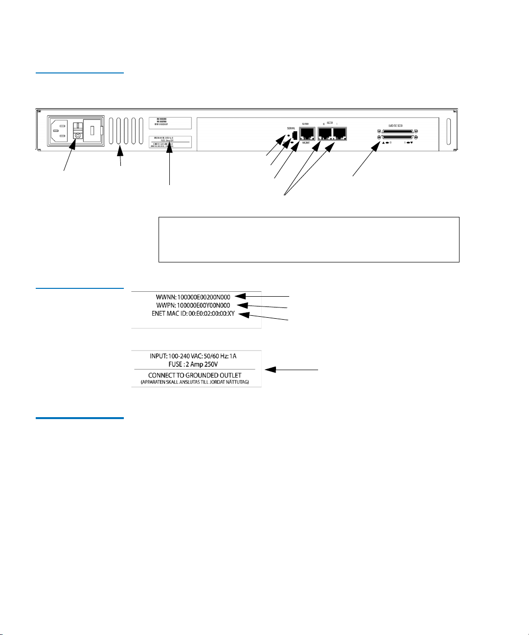
Figure 2 Back Panel
Power
switch
Air-exhaust
Vents
The air intake vents shown in figure 1 provide cooling for the unit during
operation and should always remain unobstructed. The exhaust vent for
air is located on the back panel.
Reset Button
Serial port
Ethernet port
iSCSI ports
SCSI buses
Besides the air-exhaust vents, SCSI and iSCSI interfaces are found on the
back panel. Also on the back panel, Ethernet and Serial ports provide
connections for configuration and management of the unit. The LEDs
(operation indicators) provide basic status information. In addition, a
power connector and power switch are located on the back panel along
with a Reset Button that is used to manually force a reboot of the
TC2201E. For proper operation of the TC2201E, cable connections on the
back panel should remain securely in place.
Operation Indicators 1
The TC2201E is equipped with rear panel LED indicators for monitoring
overall unit status (see
2 Quantum TC2201E User’s Guide
figure 3).
Page 23

Figure 3 TC2201E
LEDs
Chapter 1 Introduction
How the TC2201E Works
Ethernet Activity
Power/Fault
iSCSI Activity
Ethernet Link Status
iSCSI Link Status
SCSI Activity for Bus 0
SCSI Activity for Bus 1
The LED functionality of the TC2201E is detailed below:
• Power and Fault (Pwr)—This bi-color LED is green to show that power
is currently active and is continuously amber-colored to show that
the TC2201E detects a fault condition in the TC2201E.
• iSCSI (Link/Act)—When lit green, the right indicator signifies a good
iSCSI link on the port. When lit green, the left indicator signifies iSCSI
port activity.
• SCSI Bus (0, 1)—When lit, these green indicators signify SCSI activity
on the bus corresponding to the number of the indicator.
• Ethernet (Link/Act)—When lit green, the right indicator signifies a
good Ethernet link on this management port. When lit green, the left
indicator signifies Ethernet port activity on this management port.
How the TC2201E Works 1
The TC2201E is a router that translates the iSCSI protocol to and from the
SCSI Protocol—transparently transferring commands, data, and status
information—so that devices and hosts can communicate with each other.
Interconnection is provided between two SCSI buses and one or two
iSCSI networks, also making use of iSCSI’s ability to encapsulate SCSI
protocol packets.
Quantum TC2201E User’s Guide 3
Page 24

Chapter 1 Introduction
Processing SCSI Information
Figure 4 shows a host accessing SCSI tape drives and libraries via the
TC2201E.
Figure 4 Example
Configuration
Processing SCSI Information 1
The following section describes how the TC2201E processes SCSI
information when attached to iSCSI hosts.
through 5 of the process.
1 A iSCSI host issues a command. The iSCSI host encapsulates the
command in the iSCSI protocol and sends the packet to the TC2201E.
2 The iSCSI controller in the TC2201E receives the packet, interprets the
iSCSI information, and places the packet in buffer memory.
3 The TC2201E’s processor interprets the information and programs a
SCSI controller to process the transaction.
4 The SCSI controller sends the command to the SCSI device (target).
5 The SCSI target interprets the command and executes it.
4 Quantum TC2201E User’s Guide
Figure 5 illustrates steps 1
Page 25

Figure 5 Information
Processing
Chapter 1 Introduction
Processing SCSI Information
Figure 6 Flow of data
and responses
6 Data flows between the iSCSI host and SCSI target through payload
buffers (see
figure 6).
7 Response information flows from the SCSI target back to the iSCSI
host (see
figure 6).
Quantum TC2201E User’s Guide 5
Page 26

Chapter 1 Introduction
LAN-free Backup and Restore
LAN-free Backup and Restore 1
LAN-free backup and restore moves the bulk of data backup and
recovery traffic from the LAN and onto a dedicated storage network. The
TC2201E supports LAN-free backup/restore environments (see
Figure 7 LAN-free
backup
figure 7).
TC2201E Features 1
iSCSI Features 1 The TC2201E provides the following iSCSI features:
• Dual iSCSI ports (10/100/1000 baseT Ethernet)
• iSNS support
• Error Recovery Level 0
• Multiple iSCSI connections per session
• VLAN Quality of Service (QoS) support
6 Quantum TC2201E User’s Guide
Page 27

SCSI Bus Features
Chapter 1 Introduction
TC2201E Benefits
1 The TC2201E provides the following SCSI bus features:
• Auto-negotiation for Narrow, Wide, Fast, and up to Ultra160
• Concurrent commands, tagged command queuing and disconnect/
reconnect
• SCSI-2 and SCSI-3 protocols
• Connection type is VHDCI 68-pin D shell, P type connectors
• LVD/single-ended termination
• Fully supports Quantum tape libraries and autoloader devices
Management Features
The TC2201E provides the following management options:
1
• Out-of-band 10/100 Ethernet TCP/IP management access Port
• Serial 3-pin connector for terminal access
• DHCP for easier network administration
• Indexed and Auto Assigned addressing modes
• Support for SCSI-3 Commands
• Ethernet RJ-45 connector for FTP, command line, and web browser
access
• Field-updateable firmware
TC2201E Benefits 1
The Quantum TC2201E is designed to connect SCSI devices into an iSCSI
network. The Quantum TC2201E is neatly packaged in a 1U form factor
with two 1 Gb/s iSCSI ports and two LVD/SE SCSI buses. SCSI buses
automatically negotiate for Fast, Narrow, Wide, and up to Ultra160 SCSI.
External throughput is up to 200 MB/s
bi-directional per iSCSI port (or 100 MB/s one way per iSCSI port), or up
to a total of 400 MB/s bi-directional for both ports.
Quantum TC2201E User’s Guide 7
Page 28

Chapter 1 Introduction
TC2201E Benefits
Enterprise Class Performance
Ease of Use to Reduce SAN Management Costs and Complexity
Add Intelligence to SCSI Storage
1
1
The TC2201E offers enterprise class performance with memory buffer
bandwidth exceeding 1 Gb/s and delivering end-to-end throughput of
up to 400 MB/s bi-directional for both ports (or 200 MB/s each way for
both ports together). The TC2201E performs fast tape reads and writes,
which enables it to handle larger data sets while completing backup and
restore tasks within a smaller timeframe.
The Quantum TC2201E is significantly easier to install than other routers
due to the “store-and-forward” configuration feature and the Visual
Manager (VM) software. “Store-and-forward” allows configuration files
1
and TC2201E operational settings to be saved and copied to other like
routers, reducing redundant setup tasks. Using VM, service professionals
and end users can configure a TC2201E with simple “point and click”
choices on a graphical representation of the TC2201E.
The TC2201E has many features that provide intelligence to SCSI devices
and help manage SAN configurations, performance and reliability. A
short list includes Visual Manager, dynamic storage allocation (i.e. map
activation without reboot), SCSI target reset, custom mapping, and access
controls (LUN masking and management). These features of the TC2201E
provide customers with a high level of storage functionality for high
performance backup and recovery, reliability, security and manageability
in their nearline storage solutions.
8 Quantum TC2201E User’s Guide
Page 29

Chapter 1 Introduction
TC2201E Specifications
Industry Leading Inter Operability
Quantum has a proven history of industry leading inter operability,
which we incorporate into all our products. Quantum and its partners
1
have tested thousands of different configurations, discovering and
resolving many troublesome inter operability ability problems.
TC2201E Specifications 1
Physical Specifications
The physical specifications of the TC2201E are:
1
• Internal power supply with detachable power cord
• iSCSI link status and activity LEDs
• SCSI Bus activity LEDs
• Ethernet link status and activity LEDs
• Power/Fault LED
• Airflow with internal fan
• Rack mount or desktop enclosure
•Power Switch
Physical Dimensions
Operating Environment
The physical dimensions of the TC2201E are:
1
• Width 43.18cm (17.00 inches)
• Depth 27.3cm (10.75 inches)
• Height 4.37cm (1.72 inches, 1U)
• Weight approx. 4kg (9 lbs.)
The operating environment of the TC2201E is:
1
• 10 to 40°C
• 20 to 80% Relative Humidity (non-condensing)
Quantum TC2201E User’s Guide 9
Page 30

Chapter 1 Introduction
TC2201E Specifications
Non-operating Environment
The non-operating environment of the TC2201E is:
1
• -40 to +65°C
• 10 to 90% Relative Humidity (non-condensing)
Power 1 The power requirements for the TC2201E are:
• 100 - 240 VAC, Auto Sensing
• 50/60 Hz, 1.0 Amps
• Consumption Rate: No more than 119.5 BTUs of heat per hour
10 Quantum TC2201E User’s Guide
Page 31

Chapter 2
2Getting Started
This chapter describes how to install the TC2201E and what to consider
when unpacking the unit for the first time. The TC2201E can be set up as
either a desktop or rack installation and connected to various types of
devices.
Note: Read this chapter carefully and completely before working
with the TC2201E.
Before physically installing the TC2201E, consider carefully the location
for the unit installation, the intended use of the unit, and the type of
devices to which the unit will be attached.
Caution: When installing the TC2201E, use only the screws and
other hardware provided in the shipping container for the
TC2201E. Using alternate hardware may cause damage to
the unit.
Quantum TC2201E User’s Guide 11
Page 32

Chapter 2 Getting Started
Location
Location 2
The TC2201E can be placed on a desktop or mounted in a standard 19inch rack depending on the specific requirements of the installation.
The operating environment should meet the requirements found in
Physical Specifications. If you plan to use the TC2201E on a table top,
attach the stick-on feet to the bottom of the unit.
Note: The TC2201E has cooling fans mounted inside of the enclosure
and air exhaust vents on the front of the enclosure. The rear
(port-side) intake vents and the front (logo-side) exhaust vents
should remain clear of obstructions to ensure proper airflow.
Unpacking the Box 2
Unpack the shipping container of the TC2201E in an area clear of any
clutter using the following instructions:
1 Remove all items from the shipping container. Check each item for
any damage. Keep the TC2201E in the protective bag until you are
ready to install it.
2 Make sure you received all the equipment you ordered. If an item
appears missing, contact your sales representative immediately.
Mounting the TC2201E on a Desktop 2
Use the following instructions to mount the TC2201E on a table or
desktop.
1 Remove the TC2201E from the protective bag.
2 Attach the stick-on feet to the bottom of the unit.
3 Place the TC2201E on the table or desktop.
12 Quantum TC2201E User’s Guide
Page 33

Chapter 2 Getting Started
Mounting the TC2201E in a Rack
Mounting the TC2201E in a Rack 2
Before beginning installation, review the following installation
procedure. When familiar with the installation procedure, follow the
steps indicated to mount the TC2201E into a standard 19” rack using the
provided mounting materials, which include:
• One TC2201E
•Two ear brackets
• A bag of mounting screws (8 #M6x12 Phillips screws and 4 #6-
32x.312 Phillips screws)
Required Tools 2 The following tool is required for installation:
• #2 PHILLIPS screwdriver
Installing the TC2201E With Ear Brackets
To install the TC2201E with ear brackets:
1 Remove the TC2201E from the protective bag.
2
2 Determine where the TC2201E will be mounted.
Note: Place the TC2201E so the intake/exhaust vents remain
clear of obstructions to ensure proper airflow.
3 Remove any blanking panels and other equipment from the chosen
rack location.
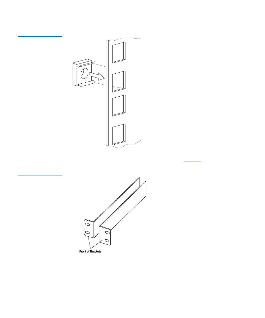
4 Install the cage nuts on the vertical mounting rails of the rack cabinet,
as shown in
figure 8 below.
Quantum TC2201E User’s Guide 13
Page 34
Chapter 2 Getting Started
Mounting the TC2201E in a Rack
Figure 8 Installing
Cage Nuts
Figure 9 Locating
front of ear brackets
5 Locate the front of the ear brackets, as shown in figure 9 below.
14 Quantum TC2201E User’s Guide
Page 35
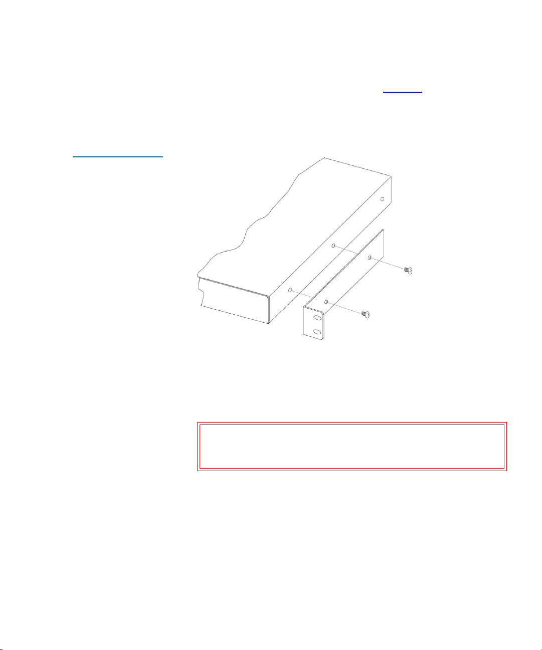
Figure 10 Attaching
the Ear Brackets
Chapter 2 Getting Started
Mounting the TC2201E in a Rack
6 Attach the ear brackets to the TC2201E, using two of the #6-32x.312
Phillips screws on each side (as shown in
figure 10 below). Position
the front of each bracket next to the end of the TC2201E that will be
facing out of the rack (see Step 7 for more information). Tighten the
screws securely.
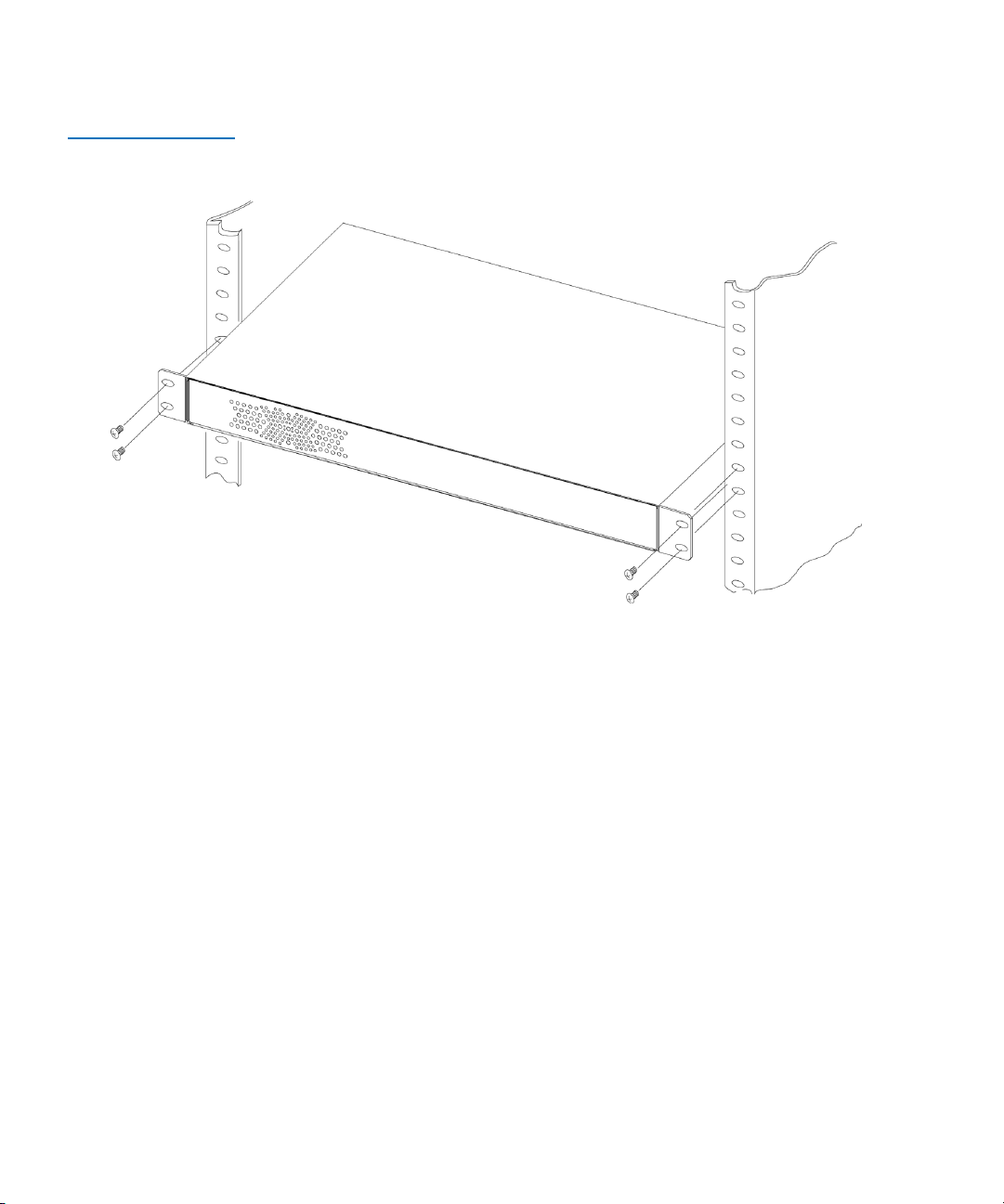
7 If you are mounting the TC2201E in the rack with the ports facing
inside the rack (shown in Figure 2-4) or with the ports facing outside
the rack (shown in Figure 2-5), attach the front of the mounting
brackets to the rack using two of the #M6x12 Phillips screws for the
front of each ear bracket. Tighten the screws securely.
Warning: To reduce injury or equipment damage, the mounting
brackets must be level. If the brackets are not level, the
TC2201E cannot be installed correctly
Quantum TC2201E User’s Guide 15
Page 36
Chapter 2 Getting Started
Mounting the TC2201E in a Rack
Figure 11 Mounting at
Front of Rack
16 Quantum TC2201E User’s Guide
Page 37
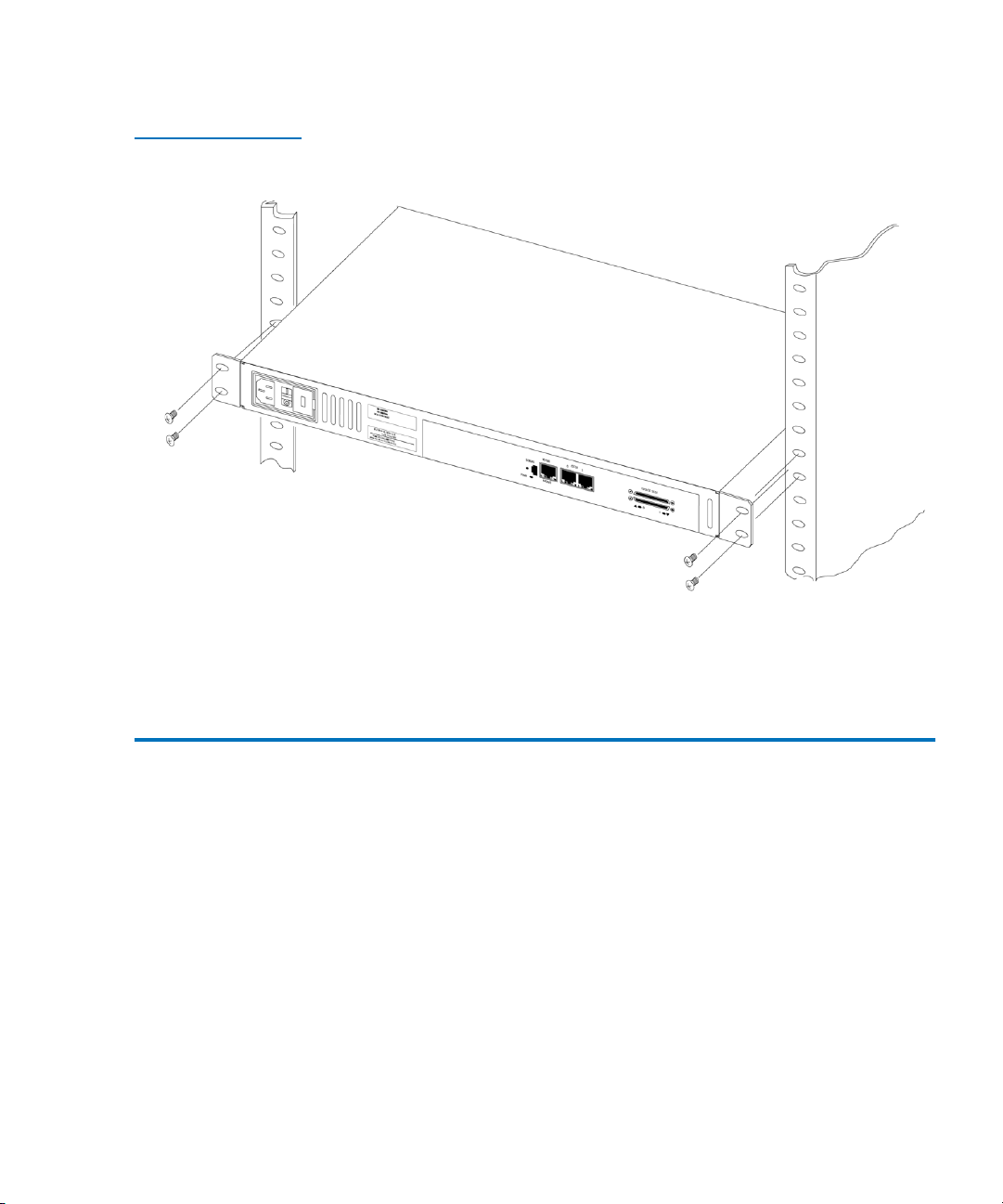
Figure 12 Mounting at
Back of the Rack
Chapter 2 Getting Started
Interfaces and Connections
Once the TC2201E is installed, you are ready to connect it to the other
system components.
Interfaces and Connections 2
There are four types of interfaces to the TC2201E:
•iSCSI
•SCSI
• RS-232 (3-pin Serial) [Service Management/Configuration Interface]
• Ethernet [Web-based Management/Configuration Interface]
Quantum TC2201E User’s Guide 17
Page 38
Chapter 2 Getting Started
Interfaces and Connections
Figure 13 Port
locations
Power
switch
Air-exhaust
Vents
Reset Button
Serial port
SCSI buses
Product ID labels
Ethernet port
iSCSI ports
Note: For convenience in configuring ports, key information is
indicated on a label located on the back panel of the
TC2201E.
Figure 14 WWN/MAC
ID label
iSCSI Connections2
WWN Name
WWP Name
Ethernet MAC ID (Physical Address)
Power Information
Before connecting the TC2201E to other iSCSI devices, it is important to
understand the configuration requirements of the environment to which
it will be connected. Failure to correctly configure an iSCSI device may
impair the operation of the network to which it is attached.
The iSCSI RJ-45 connectors on the unit can be directly connected to a
standard 10/100/1000BaseT Ethernet network.
Typical installations will have the TC2201E connected to an Ethernet
switch.
Ethernet switches may allow for individual ports to be configured for
different media types. The TC2201E must be connected to the switch port
with the appropriate Ethernet cabling for both the TC2201E and the
switch port to which it is connected.
18 Quantum TC2201E User’s Guide
Page 39
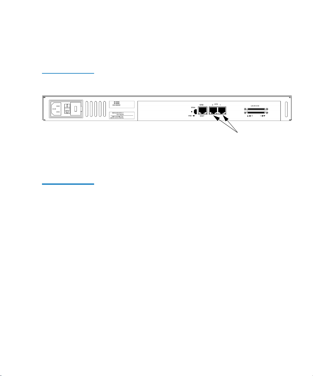
Figure 15 iSCSI ports
Chapter 2 Getting Started
Interfaces and Connections
To connect the TC2201E to an iSCSI network or host:
1 Locate the iSCSI ports on the back of the TC2201E.
iSCSI ports
2 With the TC2201E powered off, connect the TC2201E into the iSCSI
environment using the appropriate cabling. Be sure to insert the cable
connectors in the proper orientation.
SCSI Connection 2 The TC2201E can support Fast/Ultra160 Narrow/Wide SCSI, depending
on the specific configuration. The TC2201E is factory configured to
support LVD/Single-Ended buses. Two VHDCI 68-pin D-shell, P-type
connectors are located on the rear panel of the unit, allowing the unit to
be attached at the end of up to two SCSI buses. The TC2201E must always
be installed at the end of SCSI buses.
The TC2201E supplies termination power (TERMPWR) to each SCSI bus.
An internal self-resetting fuse in the TERMPWR will reset after a fault is
cleared.
Quantum TC2201E User’s Guide 19
Page 40

Chapter 2 Getting Started
Interfaces and Connections
Figure 16 High
Density SCSI Cables
Warning: During attachment of high density SCSI cables, please
note the orientation (as shown in Figure 2-11) of the high
density SCSI port connectors on the back panel of
TC2201E. Failure to maintain appropriate orientation of
the cables to the SCSI port connectors can result in damage
to the SCSI port connectors on the TC2201E.
Caution: Do not plug HVD devices to an LVD/SE bus. Failure to
heed this caution may result in severe damage to
equipment.
Caution: SCSI ports on the TC2201E are not hot-pluggable. Power
off the TC2201E whenever connecting/disconnecting the
SCSI cables.
Any SCSI cables used with the TC2201E series product must meet SCSI 2
standards and must be LVD rated (specifically low noise cabling). The
cables should be rated at 24 Ohm impedance and should have a VHDCI
68pin.8mm D-shell/P-type to Standard 68pin SCSI D-shell connector at the
20 Quantum TC2201E User’s Guide
Page 41
Chapter 2 Getting Started
Interfaces and Connections
end being attached to the TC2201E. The type of connector at the other end
of the cable will be dependent on the device being connected.
Warning: Please be advised that failure to comply with the
minimum high density cable specifications can result in
damage to the TC2201E or an operational failure of the
product.
Note: SE is not supported by SCSI-2 protocols. While it is possible to
mix SE and LVD devices on the same bus, doing so may result
in substantially decreased performance on the bus.
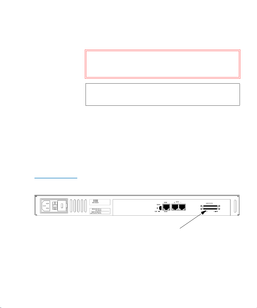
To connect the TC2201E to a SCSI bus:
1 Power off the SCSI devices on this bus.
2 Connect a SCSI cable to one of the SCSI connectors on the back panel
of the unit. The TC2201E should always be installed at the end of the
SCSI bus.
3 Make sure that the bus is terminated correctly. By default, the
TC2201E is automatically terminated. However, the device at the
other end of bus must also be terminated.
Figure 17 TC2201E
SCSI connection
SCSI buses
4 Power on the SCSI devices on this bus, but not the TC2201E.
5 After all the SCSI devices on this bus have completed their individual
POST (Power-On Self Test) processes, power on the TC2201E.
Quantum TC2201E User’s Guide 21
Page 42

Chapter 2 Getting Started
Interfaces and Connections
Ethernet Management Connection
Figure 18 TC2201E
Ethernet port
10/100BaseT Ethernet connectivity provides enhanced management and
configuration capabilities. The RJ-45 connector on the unit can be directly
connected to a standard 10/100BaseT Ethernet network.
2
If your network does not have a DHCP server, you will need to manually
configure an IP address via the serial port using the Command Line
Interface (see
appendix C, Using the Command Line Interface).
For more information about the IP network address and the visual
management system, refer to the
chapter 3, Quantum Visual Manager.
Note: For manual configuration of the IP address, the TC2201E’s
default IP address is 1.1.1.1 but this is technically not a valid IP
address. It is recommended that you change the setting to a
valid address, as described in appendix C
.
Ethernet capabilities include Telnet, FTP, and an HTTP (web browser)
support for configuration and management.
Ethernet Management port
RS-232 Serial Management Connection
The 3-pin connector on the back panel of the TC2201E provides a serial
port that is compatible with RS-232 signaling levels. The TC2201E is
designed to communicate with a terminal or any operating system
2
utilizing a terminal emulator. The baud rate, data bits, stop bits, parity,
and flow control of both the TC2201E and the host system must use the
same settings. Refer to
appendix C for more information on serial
management.
22 Quantum TC2201E User’s Guide
Page 43

Figure 19 TC2201E
Serial Port
Chapter 2 Getting Started
Interfaces and Connections
Serial port
Setting Up Serial Port Communications
Leave the TC2201E turned off until you have set up the serial port
communications on your host computer, unless serial I/O was
previously established and is currently running.
2
The TC2201E is designed to communicate with a terminal or any
operating system utilizing a terminal emulator. For example, Windows
9x, NT 4.0, or Windows 2000 operating systems can use Hyperterminal.
Be sure the baud rate, data bits, stop bits, parity, and flow control are set
correctly.
To set up serial communications with the TC2201E:
1 Leave power to the TC2201E turned off until you have set up the
serial port communications on your host terminal.
2 Plug the serial cable into one of the host computer’s serial ports
(COM1 or COM2), and then plug the other end of the serial cable into
the TC2201E’s serial port
.
Note: A 3-pin serial cable is included in the shipping container
for the TC2201E.
3 Start the terminal emulator.
4 Set the terminal emulator to use the appropriate COM port.
Note: Auto Detect or VT100 are the recommended settings for
Windows HyperTerminal emulation type.
Quantum TC2201E User’s Guide 23
Page 44

Chapter 2 Getting Started
Interfaces and Connections
5 Specify the following settings for the port:
Baud Rate: 9600, 19200, 38400, 57600, or 115200
Data Bits: 8
Stop Bits: 1
Parity: None
Connecting the Power Cable
Flow
None or XON/XOFF
Control:
Note: Before initially powering on the TC2201E, make sure all
the storage devices are powered on first and that they have
finished performing their self tests. This will help ensure
that device discovery works correctly.
6 Proceed to the following instructions on connecting the power to the
TC2201E.
The power supply used with the TC2201E supports 100 - 240 VAC (Auto
Sensing), but the correct type of power cable needed for your installation
2
should still be verified. The power cable shipped with the TC2201E is a
120 VAC 3-conductor power cable for use in the United States and
Canada. This is the power cable that should be used with the TC2201E
unless your installation requires otherwise, in which case you should
obtain the appropriate power cable as needed.
To connect the power cable to the TC2201E:
1 Connect the female end of the power cable to the power connector on
the back panel of the TC2201E.
2 Plug the male end of the power cable into the power source.
3 Switch on power to the TC2201E using the Power Switch located on
the back panel of the TC2201E.
If accessing the serial port, once you set the baud rate in the terminal
emulator, wait until the TC2201E completes the Power-On Self Test
(POST) and then the Firmware Initialization process. This can take up
24 Quantum TC2201E User’s Guide
Page 45

Figure 20 TC2201E
Power Switch and
Connector
Chapter 2 Getting Started
Configuring the TC2201E
to 90 seconds, during which time the POST and initialization
information may or may not be visible on the terminal or terminal
emulator.
The baud rate used by the terminal or terminal emulator must be
9600, 19200, 38400, 57600, or 115200. The TC2201E will not function
properly at any other baud rate.
Once the POST and firmware initiation processes are complete, the
main menu should be accessible over the serial port. Optionally, the
main menu can also be accessed over the Ethernet port as described
in the next Chapter of this manual.
Power
connector
Power
switch
Reset Button
Configuring the TC2201E 2
The TC2201E can be configured in a variety of ways. The following are
general procedures for setting up basic operation. Not all of these settings
will apply to every environment, but these guidelines should provide the
fundamental steps for configuring the TC2201E.
Configuring the TC2201E using the Visual Manager
To configure the TC2201E using the visual manager:
1 While DHCP support is enabled by default on the TC2201E, it is
2
important to ensure that the Ethernet setting for DHCP is set to
Enabled or that a valid IP address and IP gateway have been properly
Quantum TC2201E User’s Guide 25
Page 46

Chapter 2 Getting Started
Configuring the TC2201E
configured for network operation of the TC2201E. Depending on the
network environment, it may be possible to use the TC2201E’s
default IP address of 1.1.1.1 to configure the unit.
Note: In the event that DHCP is not used, note that the
TC2201E’s default IP address of 1.1.1.1 is technically not a
valid IP address. It is recommended that you should
change the setting to an IP address that is a valid address
(via the serial port using the Command Line Interface).
Refer to Using the Command Line Interface
on page 103
for information on configuring the IP address.
2 Verify that the Ethernet and iSCSI ports all have good network
connections. This can be accomplished by issuing a standard “ping”
command to the IP addresses for each port. In the event that a port
fails to respond, check all cable connections (use new cables where
necessary) and be sure there is a good link light showing on the
network switch for all connections to the TC2201E.
3 To begin configuration of the TC2201E, enter the IP address of the
Ethernet management port into the web browser address field and
press the
Enter key. The home page of the TC2201E should appear. If
not, please verify the IP address or use the Command Line Interface
instructions in the next section.
4 In the Home page of the Visual Manager interface, select “Ethernet”
from the Main menu on the left.
5 When the security prompt appears, enter the appropriate user name
and password values and then select the
user name is ‘root’ and the default password is ‘password’.
6 The Ethernet page will appear. Select each Ethernet port from the
menu on the left and verify that all Ethernet settings are correct for
the network environment that the TC2201E is connected to.
7 Select the Discovery page to verify that all target devices are visible as
expected and that the status for each device appears as expected (i.e.
in the “UP” state). If any device is shown in the “DOWN” state,
inspect that device. If a device fails to appear at all, make sure the
26 Quantum TC2201E User’s Guide
Submit button. The default
Page 47

Chapter 2 Getting Started
Configuring the TC2201E
device is powered on and check cable connections. It may be
necessary to perform a manual discovery (select
GO button) or to
reboot the TC2201E (menu selection on left).
Note: During reboot, some older browsers will need to be
manually returned to the desired page after the reboot
page counter has completed counting down to "0".
8 Select the SCSI Bus page. SCSI ID 7 is the default SCSI Initiator ID for
each of the TC2201E’s SCSI buses. If any devices attached to a
TC2201E bus are using SCSI ID 7, then that bus's Initiator ID must be
changed. To change a bus's Initiator ID: Select the desired bus from
the TC2201E GUI or the SCSI Bus submenu. Then use the Initiator ID
field drop-down list to select an unused ID number. Click the Submit
button to record the change.
If the TC2201E does not see all of the devices expected, check that the
initiator ID(s) are set to a unique value for each bus attached to
devices. For any changes, submit those changes and reboot the
TC2201E.
Configuring the TC2201D Using the Command Line Interface
You have now successfully configured the TC2201E. This procedure
may not apply to all situations but does address most key issues
required for initial setup.
To configure the TC2201E from the command line interface:
1 Establish communications over the serial port and then bring up the
2
Command Line Interface (CLI).
2 In the main menu of the CLI, several menu options should be visible.
Select menu option
option
3, “Ethernet”.
1, “Perform Configuration” and then menu
3 To enable remote management capabilities, toggle DHCP to Enabled
or enter a valid IP address and IP gateway, so that the TC2201E is
configured properly for network operation. When Ethernet settings
are complete, select X to go back to the main configuration menu.
4 Select menu option 5 to access the SCSI Bus menu. SCSI ID 7 is the
default SCSI Initiator ID for each of the TC2201E’s SCSI buses. If any
devices attached to a TC2201E bus are using SCSI ID 7, then that bus's
Initiator ID must be changed. To change a bus's Initiator ID: Select
Quantum TC2201E User’s Guide 27
Page 48

Chapter 2 Getting Started
Save Backup Version of Configuration
the desired bus by pressing the Enter key. Then use the Edit Initiator
Settings menu option to make changes. Select X to return to the
Configuration menu.
5 Select the letter A from the Configuration Menu to save your
configuration changes to the TC2201E. Once the TC2201E saves your
configuration changes, enter X to exit to the Main menu.
6 Select menu option 2 to access the System Utilities menu.
7 Select menu option 1 to access the System Statistics menu.
8 Select menu option 1 to access the Display Parallel SCSI Protocol
Status menu.
9 Select menu option 2 to access the Display Attached SCSI Devices
menu.
10 Select menu option 4 to display all local SCSI devices. If any device is
shown in the “DOWN” state, inspect that device. If a device fails to
appear at all, make sure the device is powered on and check cable
connections. It may be necessary to perform a manual discovery
(select menu option 1, 2, or 3) or to reboot the TC2201E (from main
menu). Select X four times to return to the Configuration menu.
11 Select menu option 4 to reboot the TC2201E. In about 2 minutes, the
TC2201E will once again display the main menu.
12 If the TC2201E does not see all of the devices expected, repeat step 3
above, and check that the initiator ID(s) are set to a unique value for
the selected bus. Again, you must save any changes and reboot the
TC2201E.
You have now successfully configured the TC2201E. This procedure
may not apply to all situations, but does address most key issues
required for initial setup.
Save Backup Version of Configuration 2
Once all desired configuration settings are in place, it is recommended to
save a backup version of the configuration settings. By doing so, this will
help ensure that in the event of a serious problem such as a forgotten user
name or password, it will be possible to restore all the settings. For more
information, see
28 Quantum TC2201E User’s Guide
Using the FTP Interface on page 155.
Page 49

Chapter 2 Getting Started
Advanced Configuration Options
Advanced Configuration Options 2
The following two sections provide some advanced configuration tips
that go beyond the quick setup procedures listed above.
iSCSI Configuration
For iSCSI environments, the TC2201E provides a number of optional
configuration settings that can be used to enhance operation and security.
2
For more information about the settings described in this section, see
Chapters 6 and 7 of this manual.
Secure Connections 2
CHAP (Challenge-Handshake Authentication Protocol) provides a secure
procedure for connecting to systems, as follows:
1 After a link is made, the TC2201E sends a challenge message to the
connection requestor. The requestor responds with a value obtained
by using a one-way hash function.
2 The TC2201E checks the response by comparing it its own calculation
of the expected hash value.
3 If the values match, the authentication is acknowledged; otherwise
the connection is usually terminated.
At any time, the TC2201E can request the connected party to send a
new challenge message. CHAP identifiers are changed frequently
and authentication can be requested by the TC2201E at any time.
Port Failover 2
The iSCSI Portal Group Settings primarily serve to provide port failover
functionality for the TC2201E. By default, the TC2201E is set to use one
Portal Group for both ports, which effectively enables failover capability
between the two iSCSI ports.However, this option can be disabled so that
each port can be mapped separately.
Quantum TC2201E User’s Guide 29
Page 50

Chapter 2 Getting Started
Advanced Configuration Options
Automated Device Discovery 2
iSNS servers maintain information about iSCSI clients and will respond
to iSNS protocol queries and requests, and initiate iSNS protocol State
Change Notifications. To use iSNS with the TC2201E, simply enable the
TC2201E as a client and then enter a DNS name or IP address for up to
three iSNS servers.
The default setting is Disabled. When enabled, the TC2201E will function
as an iSNS client and will initiate transactions with iSNS servers using the
iSNSP. The iSNS client is a process that is co-resident in the TC2201E, and
which can register device attribute information with the iSNS server. The
capability is used for automated device discovery.
SCSI Configuration
For SCSI devices, the TC2201E provides a number of optional
configuration settings that can be used to enhance operation and security.
2
Buffered Tape Writes 2
Buffered Tape Writes is an option designed to enhance system
performance. By returning status on consecutive write commands prior
to the tape device receiving data, Buffered Tape Writes remove the
latency of waiting for responses from the tape device. In the event that
data does not transfer correctly for any reason, the router will return a
check condition on a subsequent command.
Commands other than Write(6) are not issued until status is received for
any pending write. Also, status is not returned until the device completes
the command. For instance, when a synchronizing command is sent to a
drive, such as sending a Write File mark, a good status means all prior
commands have been successfully completed and data has been
successfully written to the medium. This is appropriate for such tasks as
file backup/restore.
Note: By default, the Buffered Tape Writes option is disabled. If the
application requires confirmation of individual blocks being
written to the medium, such as audit trail tapes or log tapes,
this option should be disabled.
30 Quantum TC2201E User’s Guide
Page 51

Chapter 3
3Quantum Visual Manager
This chapter describes the Quantum Visual Manager (QVM). The current
configuration and operating status of the TC2201E can be accessed from
any standard Web browser, after the user logs in with the appropriate
username and password. Information is presented in HTML format in
accordance with the W3C specification for HTML 3.2. Current W3C
Recommendations and other technical documents can be found at
/www.w3.org/TR.
Visual Manager allows access to configuration settings such as:
• Baud rate of the serial port
• iSCSI settings
http:/
• Ethernet address
• Device maps and host associations
• Trace level and event log settings
Most settings may be changed and saved to the TC2201E.
Note: Unless otherwise indicated, configuration changes take effect
when the unit next powers on or reboots.
Quantum TC2201E User’s Guide 31
Page 52

Chapter 3 Quantum Visual Manager
Accessing Visual Manager
Accessing Visual Manager 3
1 Connect a 10baseT or 100baseT Ethernet cable to the TC2201E.
2 Apply power to any connected SCSI or iSCSI devices.
3 After all attached devices have gone through their power up routines,
boot up the TC2201E.
4 Turn on the host computer.
5 If the IP address for the TC2201E is known, open the computer’s Web
browser and enter the IP address into the Address field. The factory
default of the TC2201E has DHCP enabled. To disable DHCP, refer to
appendix C, Using the Command Line Interface for information on
disabling the DHCP option.
Note: For manual IP address configuration, the TC2201E has a
default fixed IP address of 1.1.1.1 but this is technically not a
valid IP address. For remote access from WAN or Internet
locations, the IP address must be changed to a valid IP
address. Valid IP addresses have the form x.x.x.x where each x
is an integer in the range of 0 to 255.
If you do not know the IP address of the TC2201E, then connect to the
TC2201E using the serial (RS-232) connection (a 3-pin serial cable is
included with the TC2201E). Current settings can be viewed and
changed from the Ethernet Configuration Menu of the serial
interface.
Note: To access the QVM user interface, the TC2201E must be
assigned an IP address.
Note: If the TC2201E is to use a static IP address, the default IP
address 1.1.1.1 should be changed to an address that is
appropriate for the IP network it will reside on. Note that the
default IP address can be used in a direct connection between
the TC2201E and the host computer via a crossover Ethernet
cable.
32 Quantum TC2201E User’s Guide
Page 53

Chapter 3 Quantum Visual Manager
Accessing Visual Manager
Note: For DHCP usage information, see the Network settings in this
chapter and in Appendix D.
Note: Unless otherwise indicated, configuration changes take effect
when the unit next powers on or reboots.
6 Once the host computer's web browser can access the TC2201E,
Quantum Visual Manager (QVM) will display the TC2201E's "Home
page" in the browser window. This page provides a high-level
snapshot of the TC2201E's status, and is accessible to anyone who
knows (and can reach) the TC2201E's IP address. The Report Page is
also accessible without needing special access. However, additional
TC2201E information, and all TC2201E configuration settings, are
user- and password-protected. Selecting other options will cause a
login window to appear, where the user can enter a user name and
password. The TC2201E defaults are
root for user name and password
for password. This information is required only once per session
(described below).
Note: For the QVM interface’s dynamic display of the TC2201E
configuration to be presented properly, use version 6.2 or later
of Netscape’s browser on non-Solaris platforms, or Netscape
version 6.2.3 for Solaris platforms. If using Internet Explorer,
use revision 6.0 or later.
Note: It is recommended to change the user name and password
from the defaults. For more information, see Main Menu
>
System > User Settings.
7 Upon successful login, the user has initiated a "session", and has full
access to the TC2201E QVM for the duration of the session. A session
ends when the user exits all instances of the web browser. Log-in will
be required again, via the TC2201E's home page, to initiate a new
session.
Note: To end the current session of Visual Manager, it is necessary to
close all instances of the browser window. Merely navigating
the browser to another URL is not sufficient to end the current
session.
Quantum TC2201E User’s Guide 33
Page 54

Chapter 3 Quantum Visual Manager
Making Changes via Visual Manager
Making Changes via Visual Manager 3
To make changes to settings, use a standard keyboard and mouse to enter
new information. Select the Submit button to send changes from the Web
browser to the TC2201E. Other than dynamic mapping changes,
configuration changes will not take effect until the next time the TC2201E
reboots. The unit can be forced to reboot by selecting the Reboot option
from the Main Menu.
Detailed instructions about all settings are provided later in this chapter.
Note: It is recommended not to bookmark Visual Manager pages with a
Web browser. Because configuration information is transmitted via
URLs, the use of bookmarks could cause the TC2201E to be
configured with information present when the bookmark was
created. For similar reasons, it is also recommended not to use
navigation features of the Web browser (such as the Back or Refresh/
Reload buttons) to navigate Visual Manager.
It is recommended that you navigate only using the Web page links
contained in Visual Manager itself. Depending on the Web browser used,
these links will often appear as highlighted text. By clicking on these
links, Visual Manager can be safely navigated.
When Visual Manager for the TC2201E is accessed, the TC2201E home
page appears as follows.
34 Quantum TC2201E User’s Guide
Page 55
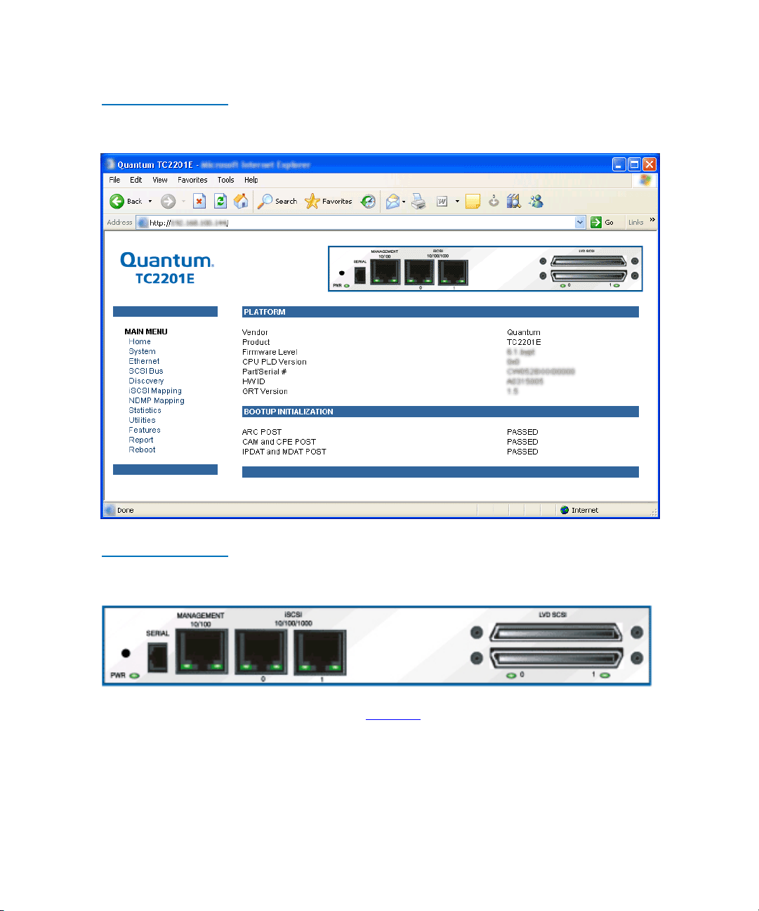
Figure 21 Visual
Manager Home Page
Chapter 3 Quantum Visual Manager
Making Changes via Visual Manager
Figure 22 TC2201E
Image
A port-side view (figure 22) of the TC2201E is shown on the home page.
On all password protected pages of the Visual Manager interface the
TC2201E image is interactive, as described below:
• Left-clicking on a port opens a menu for making changes to settings
for that particular port.
The interactive TC2201E image is available for most menus.
Quantum TC2201E User’s Guide 35
Page 56

Chapter 3 Quantum Visual Manager
Main Menu
Figure 23 Main Menu
The main menu on the left side of the TC2201E home page provides a list
of menu items that are links to various TC2201E functions, information,
and other menus.
Main Menu 3
The following are descriptions of the menu items listed under the Main
Menu category.
Main Menu > System
36 Quantum TC2201E User’s Guide
This page provides access to the System information and settings.
3
Page 57
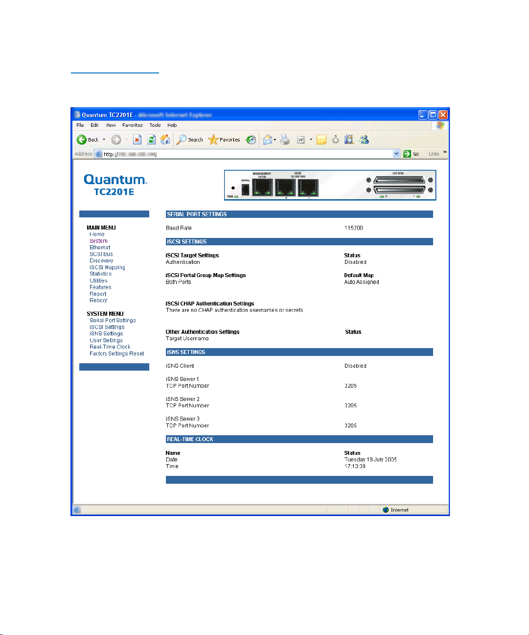
Figure 24 System
Page
Chapter 3 Quantum Visual Manager
Main Menu
This page shows system status and allows configuration of standard
system components and ports.
Quantum TC2201E User’s Guide 37
Page 58

Chapter 3 Quantum Visual Manager
Main Menu
Main Menu >
System
> Serial
Port Settings
Figure 25 Serial port
settings page
This page shows the current baud rate for the serial port and allows it to
be changed.
3
To make any changes, modify the entries by using the field’s down arrow
and selecting a choice. Then select the Submit button. Baud Rate sets the
serial port baud rate. The baud rate shown is the current setting. The
default Baud Rate setting is 115200.
38 Quantum TC2201E User’s Guide
Page 59
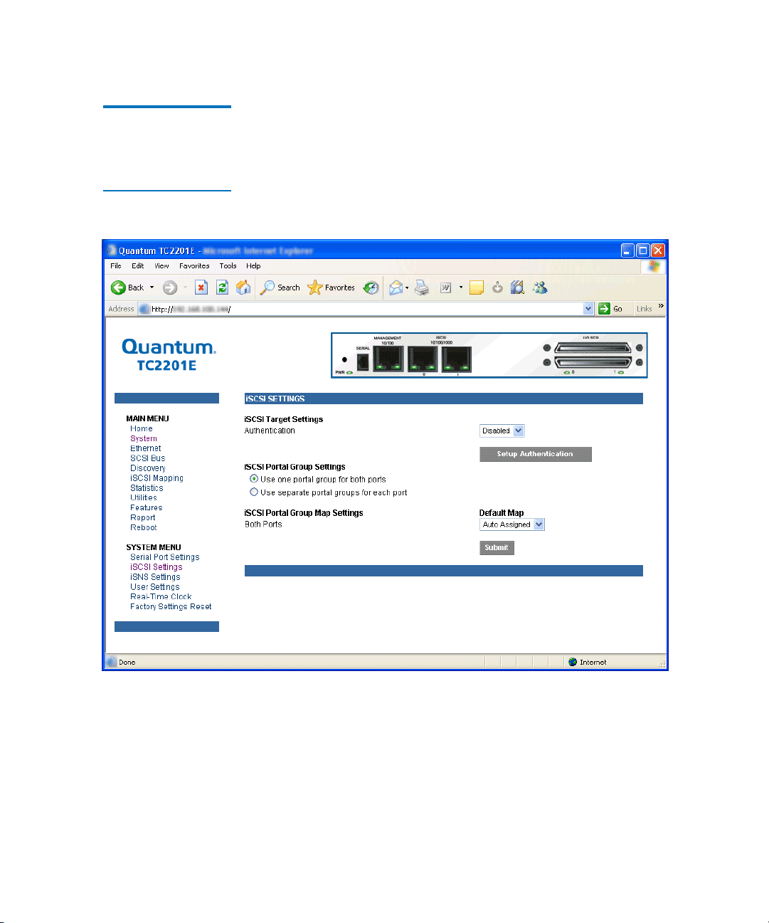
Chapter 3 Quantum Visual Manager
Main Menu
Main Menu >
System
> iSCSI
Settings
Figure 26 iSCSI
Settings Page
This page allows for configuration of iSCSI settings.
3
To make any changes, modify the entries as described below and then
select the Submit button.
iSCSI Target Settings
• Authentication can be toggled between Enabled and Disabled. The
default setting is Disabled. When set to Enabled, CHAP
authentication for iSCSI is enabled.
Quantum TC2201E User’s Guide 39
Page 60

Chapter 3 Quantum Visual Manager
Main Menu
• Setup Authentication button opens the iSCSI Authentication page.
This page consists of entry fields for CHAP name, Initiator Secret,
and Target Secret, as well as a field for Target CHAP Name.
Figure 27 iSCSI
Authentication
Settings Page
• CHAP Names are 1 to 255 characters in length and Initiator/Target
Secrets are 12 to 16 characters in length. Target CHAP Name is 1-18
characters.
•Select Delete All to remove all CHAP Authentication User Settings.
Delete All does not remove the Target CHAP name.
• For each existing entry, select Edit to make changes or Delete to
remove specific entries.
40 Quantum TC2201E User’s Guide
Page 61

Chapter 3 Quantum Visual Manager
Main Menu
•Select Add in make a new entry.
•Select Save to save the CHAP authentication changes. These changes
will become activated after the next time the TC2201E reboots.
iSCSI Portal Group Settings (continued from iSCSI Settings Page)
• iSCSI Portal Group Settings can be toggled between the following
two settings:
• Use one portal group for both ports: By default, the TC2201E is
set to use one Portal Group for both ports, which enables failover
capability between the two iSCSI ports.
• Use separate portal groups for each port: This option disables
failover capability between the two iSCSI ports, so that each port
can be mapped separately.
iSCSI Portal Group Map Settings
• iSCSI Portal Group Map Settings allows selection of the default
map(s) to the current iSCSI portal group(s). Map selections include
Auto Assigned and Indexed.
Once all changes are made, select the Submit button to send the changes
to the TC2201E. Changes will become activated after the next time the
TC2201E reboots.
Quantum TC2201E User’s Guide 41
Page 62

Chapter 3 Quantum Visual Manager
Main Menu
Main Menu >
System
> iSNS
Settings
Figure 28 iSNS
Settings Page
This page allows for configuration of iSNS settings.
3
iSNS servers maintain information about iSCSI clients and will respond
to iSNS protocol queries and requests, and initiate iSNS protocol State
Change Notifications.
42 Quantum TC2201E User’s Guide
Page 63

Chapter 3 Quantum Visual Manager
Main Menu
To use iSNS, enable the TC2201E as a client and then enter a DNS name
or IP address for up to three iSNS servers. To make changes or to
discontinue communication with a server, change or clear the
identification field(s), select the
Submit button, and then reboot the
TC2201E to activate changes.
• iSNS Client can be toggled between Enabled and Disabled. The
default setting is Disabled. When enabled, the TC2201E will function
as an iSNS client and will initiate transactions with iSNS servers
using the iSNS Protocol. The iSNS client is a process that is coresident in the TC2201E, and which can register device attribute
information with the iSNS server. The capability is used for
automated device discovery.
• Server 1, Server 2, and Server 3 can be set up by entering a DNS name
or IP address into the field for iSNS Server and entering the server
TCP Port into the field TCP Port. The standard value for TCP Port is
3205.
Quantum TC2201E User’s Guide 43
Page 64
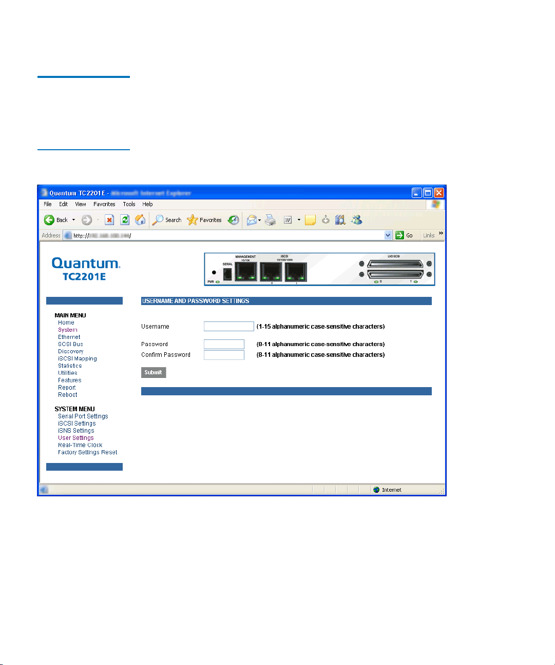
Chapter 3 Quantum Visual Manager
Main Menu
Main Menu >
System
> User
Settings
Figure 29 User
settings page
This page allows for setup of security options for username and
password.
3
Security settings include the User Name and Password for the TC2201E.
The administrator user name and password should be unique and kept
confidential. It is recommended to use a combination of letters and
numbers when creating user names and passwords. For the password,
enter the password in the Confirm Password field to help ensure there
are no typos made in the password. Then, select the
activate the user name and password you have setup.
44 Quantum TC2201E User’s Guide
Submit button to
Page 65

Chapter 3 Quantum Visual Manager
Main Menu
The default settings are ‘root’ for the user name and ‘password’ for the
password.
Note: The security settings entered here affect all user interfaces of
the TC2201E after reboot of the TC2201E.
Note: In the event that either or both the user name and password
are forgotten, it is possible to reset the user name and
password to their default values by resetting the TC2201E to
factory defaults from the Command Line Interface using the
serial port (see appendix C
on page 103). Note that resetting to
factory defaults from the serial port will also reset all other
configuration settings to factory defaults, as well as erase all
current maps. It is recommended to capture a copy of the
system report (available from the System Utilities Menu) in
order to make reconfiguration easier.
Quantum TC2201E User’s Guide 45
Page 66
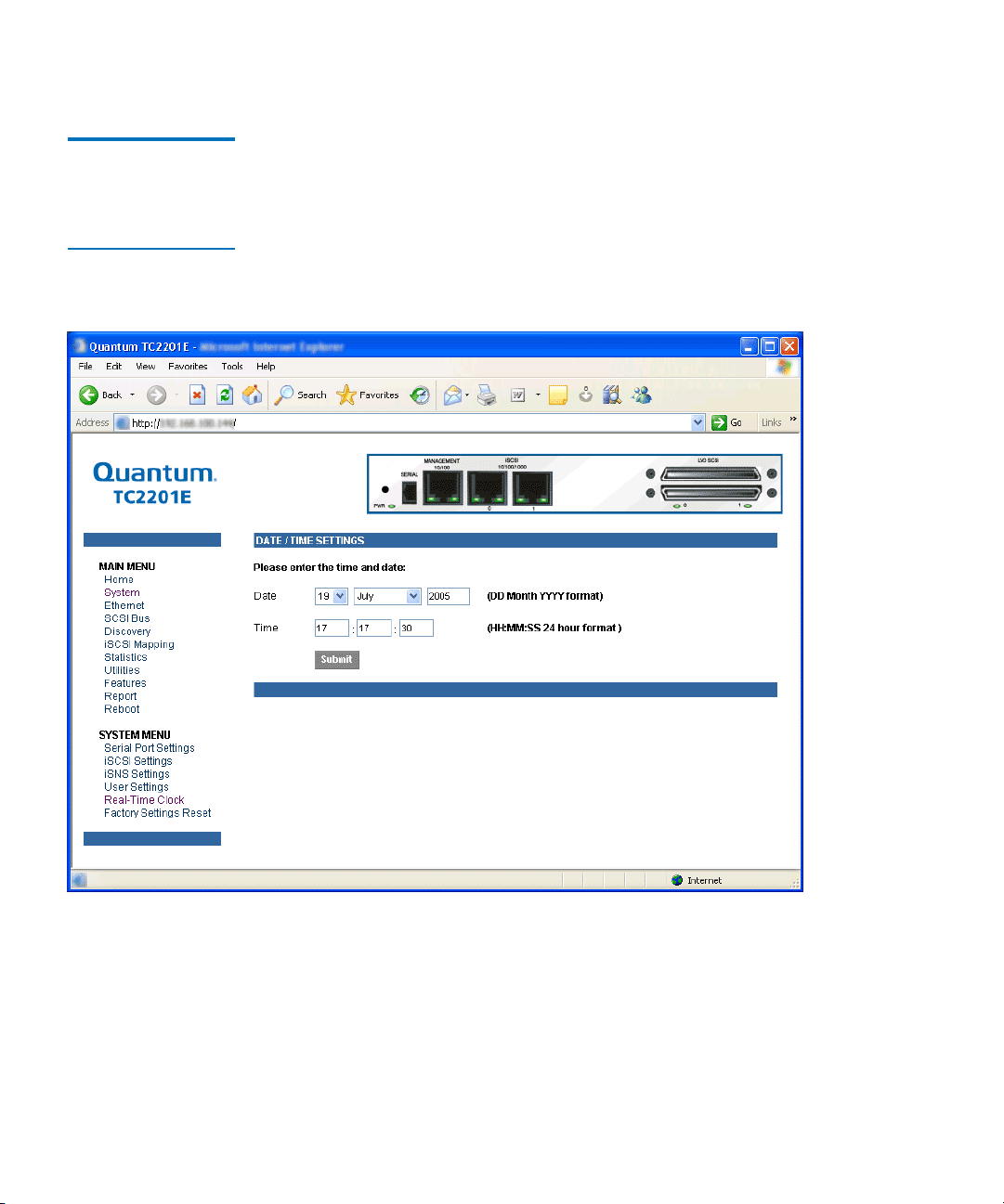
Chapter 3 Quantum Visual Manager
Main Menu
Main Menu >
System
> Real
Time Clock
Configuration
Figure 30 Real Time
Clock Configuration
Page
This page allows for set up of the date and time.
3
To make any changes, modify the entries as described below and then
select the
Submit button.
• Date Settings are for setting the date, month, and year. Use a four
digit number to represent the year.
46 Quantum TC2201E User’s Guide
Page 67

Chapter 3 Quantum Visual Manager
Main Menu
• Time Settings are for setting the hours, minutes, and seconds. This is a
24 hour clock.
Note: Be sure to correctly set the time and date in the Real Time Clock
configuration menu so that event logging is accurate.
Main Menu >
System
> Factory
Settings Reset
This page allows the TC2201E to be reset to the factory default settings.
The TC2201E must be rebooted before the reset settings will take effect.
3
Note: Resetting to factory defaults from the QVM interface will not
affect ethernet connectivity. User configured values for the IP
address, gateway, and subnet mask are retained after the
TC2201E resets. Note that user names and passwords are NOT
retained.
Note: Settings are not reset to factory defaults until the TC2201E is
rebooted.
Quantum TC2201E User’s Guide 47
Page 68
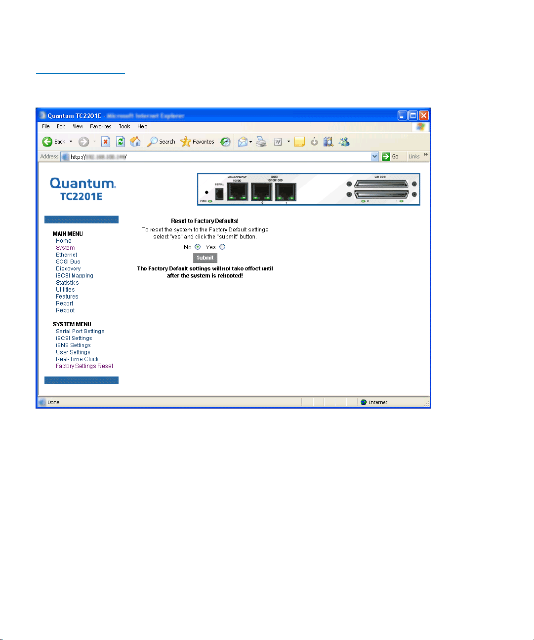
Chapter 3 Quantum Visual Manager
Main Menu
Figure 31 Factory
Settings Reset Page
When this option is selected, a confirmation message will appear to verify
the selection. If a response of
Yes is given to the confirmation message,
current TC2201E activities will be disrupted while the unit resets the
current configuration to the factory defaults and saves those options to
FLASH memory as the current configuration.
48 Quantum TC2201E User’s Guide
Page 69
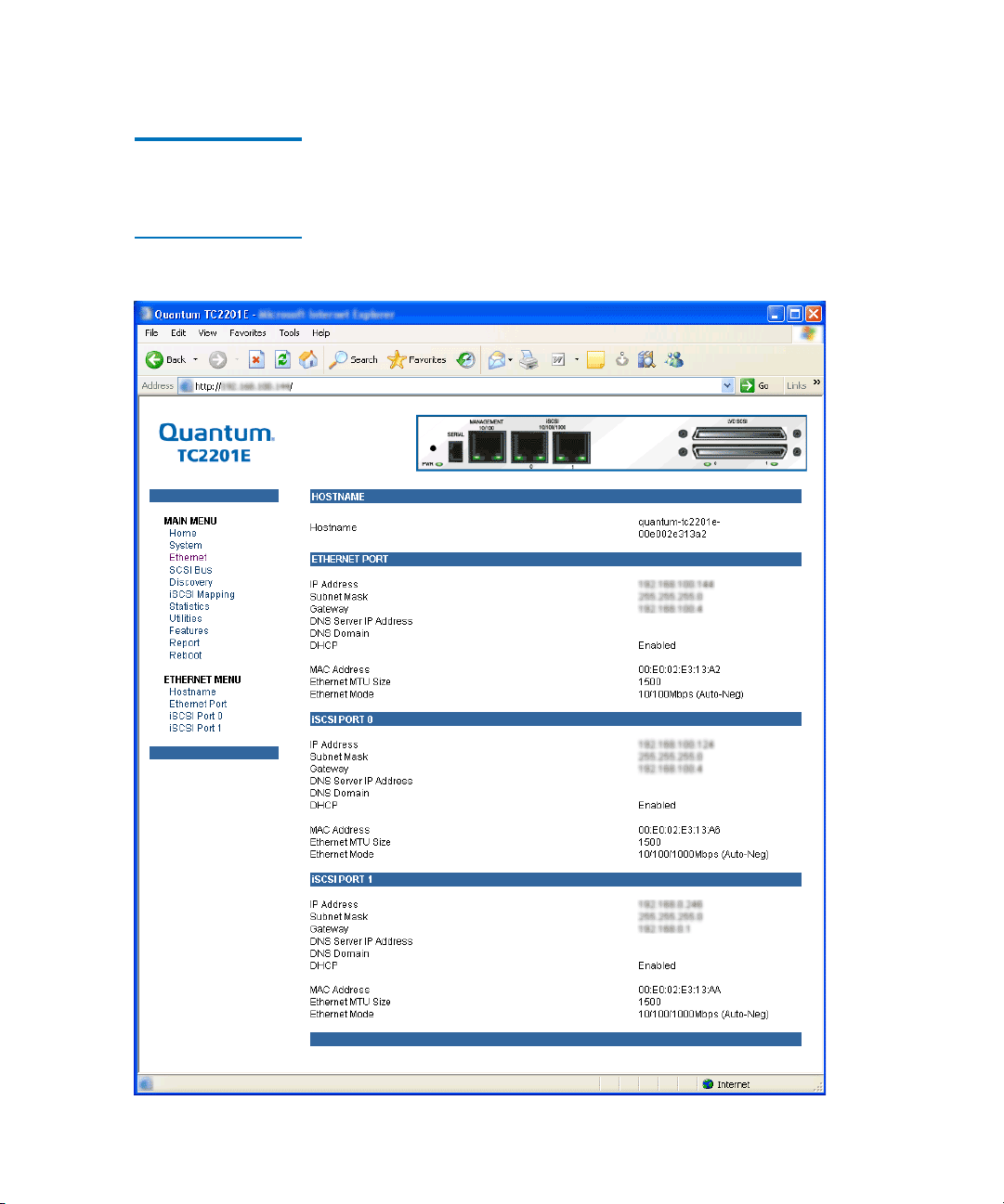
Chapter 3 Quantum Visual Manager
Main Menu
Main Menu > Ethernet
Figure 32 Ethernet
Settings Page
This page provides status and links for Ethernet and iSCSI port
configuration pages.
3
Quantum TC2201E User’s Guide 49
Page 70
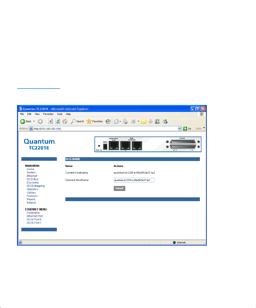
Chapter 3 Quantum Visual Manager
Main Menu
To make any changes, modify the entries as described below and then
select the
• Hostname is an alphanumeric entry of one word up to 255 characters
long. To change this entry, select hostname from the Ethernet Menu
to open the Hostname page. From the hostname page, changes to the
hostname can be entered into the Desired Hostname field. Select the
Submit button to accept the changes.
Figure 33 Host name
Page
Submit button.
• Ethernet Port opens the following port configuration page:
50 Quantum TC2201E User’s Guide
Page 71
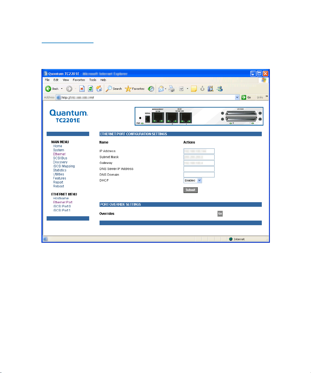
Figure 34 Ethernet
Port Configuration
Page
Chapter 3 Quantum Visual Manager
Main Menu
Both the Ethernet management port and the two iSCSI ports can be
configured for appropriate Ethernet network settings.
• IP address is the IP address of the TC2201E. The default setting for
the Ethernet port is 1.1.1.1. The default setting for iSCSI Port 0 is
169.254.1.1. The default setting for iSCSI Port 1 is 169.254.1.2.
• Subnet Mask is the IP subnet mask for the TC2201E. The default
setting is 255.255.255.0.
• IP Gateway is the IP address of the gateway for the Ethernet network
connected to the TC2201E. The default setting is 0.0.0.0.
Quantum TC2201E User’s Guide 51
Page 72

Chapter 3 Quantum Visual Manager
Main Menu
• DNS Server IP Address is the IP address for the DNS server and
should be similar in form to XXX.XXX.XXX.XXX where each XXX
represents an integer in the range of 1 to 255.
• DNS Domain is the domain name used by the DNS server. For
example, a domain name could appear similar to
“server.company.com”.
• DHCP enables/disables support for Dynamic Host Configuration
Protocol (DHCP). When enabled, the TC2201E will retrieve a
dynamic IP address from a DHCP server located on the Ethernet
network that the TC2201E is connected to. The default setting is
Enabled. If DHCP is changed from Disabled to Enabled, it is
necessary to reboot the TC2201E before an IP address will be
requested from the DHCP server. After the TC2201E finishes
rebooting, the QVM session will have to be restarted. The TC2201E's
IP address will be different than the former non-DHCP IP address.
Note: To use the DHCP feature, a DHCP server must be operational
on the Ethernet network connected to the TC2201E. If the
DHCP feature is used when there is no DHCP server, the
standard for DHCP requires that the TC2201E wait three
minutes for a response from a DHCP server before timing out.
During this period, the TC2201E menus and functions will not
be accessible.
A DHCP server may allow the setup of a lease reservation for an IP
address if provided with the MAC address of the TC2201E. This
forces the DHCP server to always provide the same IP address to the
TC2201E. This setup is useful for remote management of the TC2201E
via Telnet or Visual Manager. Because the method of setting up a
lease reservation varies depending on the DHCP server, it is
recommended to contact your Network Administrator for assistance.
• Override Settings are provided to enhance inter operability with some
devices that require special consideration during setup of the
TC2201E. Access to the Overrides Settings is reserved for authorized
Quantum technicians. Selecting the Go button opens a login prompt
for which an authorized technician will have the appropriate user
name and password.
52 Quantum TC2201E User’s Guide
Page 73
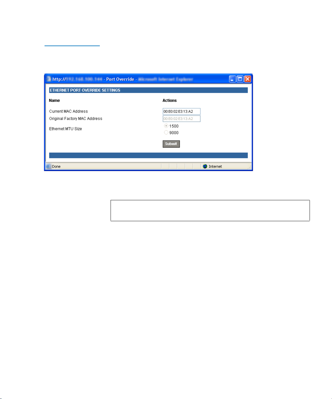
Figure 35 Ethernet
Overrides Settings
Page
Chapter 3 Quantum Visual Manager
Main Menu
To finalize any changes for the override settings, select the Submit button
on the Ethernet Override Settings page.
Note: Override settings should not be changed except by or under
the direction of an authorized Quantum technician.
• Current MAC address is the current Media Access Control (MAC)
address configured for the TC2201E. The MAC address is a hardware
address that uniquely identifies each physical node on an Ethernet
network. While the MAC address can be changed, it is highly
recommended not to change this address.
• Original Factory MAC address is the MAC address assigned by the
hardware manufacturer to the Ethernet adapter in the hardware. The
TC2201E comes initialized with this assigned MAC address.
• Ethernet MTU Size is the Maximum Transmission Unit (MTU) for
Ethernet. This setting can be configured for 1500 or 9000 byte frames.
The Ethernet Management port is permanently set to 1500 and cannot
be changed. The default setting for the iSCSI ports is also 1500 but a
value of 9000 can be configured for jumbo frame support for iSCSI
frames.
Quantum TC2201E User’s Guide 53
Page 74

Chapter 3 Quantum Visual Manager
Main Menu
Main Menu > SCSI Bus
Figure 36 SCSI Bus
Page
This page allows for viewing the current SCSI attributes and settings for
buffered tape writes.
3
To make any changes, modify the entries as described below and then
select the
SCSI Bus 0 or 1
Submit button.
Selecting either of these two options opens the following page for
configuration of SCSI bus settings.
54 Quantum TC2201E User’s Guide
Page 75
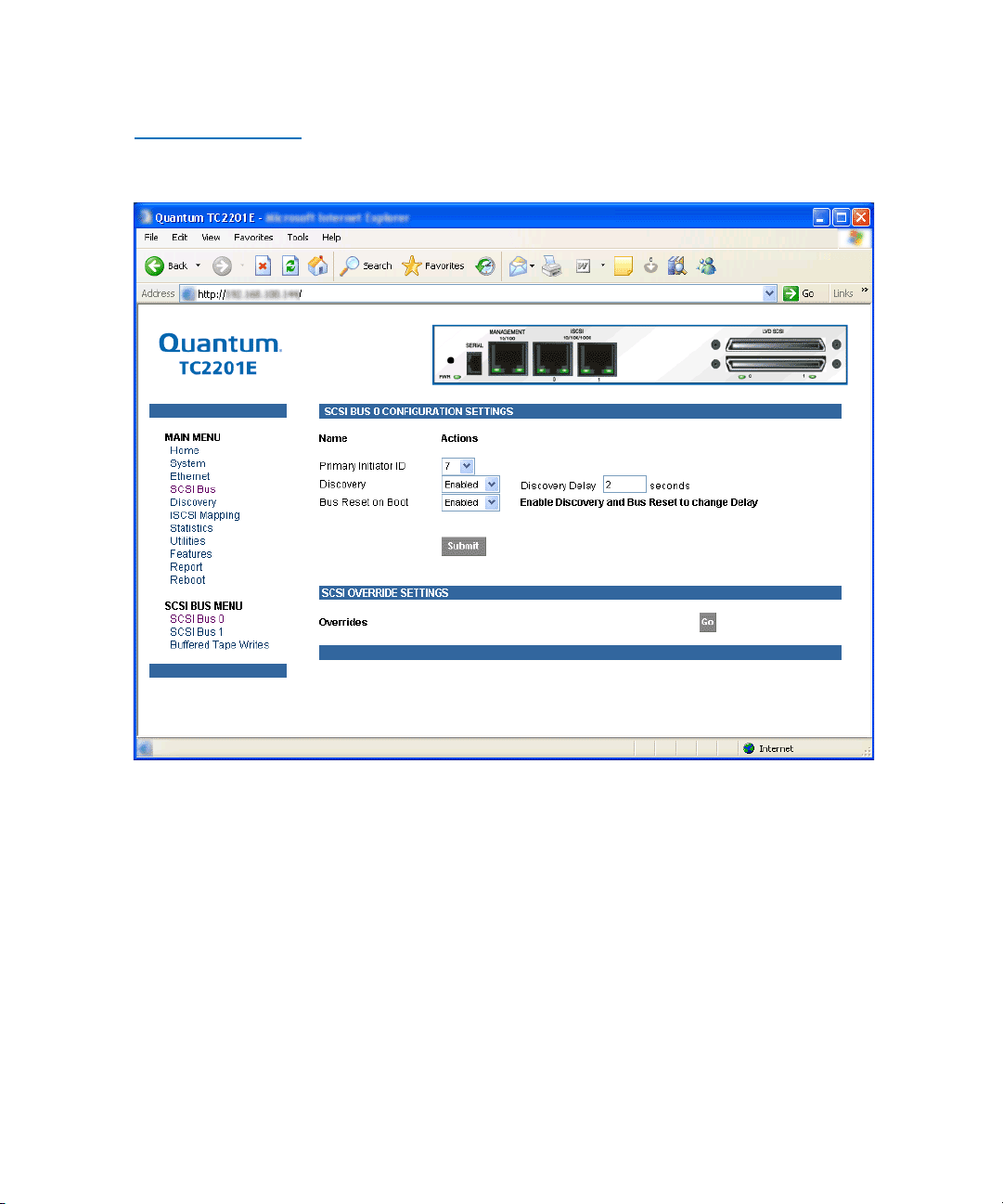
Figure 37 SCSI bus
Configuration Page
Chapter 3 Quantum Visual Manager
Main Menu
• Primary Initiator ID must be assigned an Initiator ID. This ID should be
a unique ID on the bus. The default setting is 7.
• Discovery enables/disables device discovery on this SCSI bus. The
default setting is
Enabled.
• Discovery Delay is the time in seconds that the TC2201E waits after a
power-up or reboot process (which typically takes approximately 2
minutes) before starting to discover SCSI devices. Quantum
recommends you set the value to at least 2 seconds to ensure all SCSI
devices complete their individual power-ups. However, the user
should be aware this delay is added to the time it takes for the
TC2201E to reboot and for QVM to be active again. The default
setting is 2 seconds.
Quantum TC2201E User’s Guide 55
Page 76

Chapter 3 Quantum Visual Manager
Main Menu
• Bus Reset on Boot enables/disables automatic discovery of SCSI
devices after an initial power up or reboot of the TC2201E. The
default setting is
• Override Settings are provided to enhance inter operability with some
storage devices that require special consideration during setup of the
TC2201E. Access to the Overrides Settings is reserved for authorized
Quantum technicians. Selecting the Go button opens a login prompt
for which an authorized technician should have the appropriate user
name and password.
Figure 38 SCSI
Overrides Settings
Page
Enabled.
To finalize any changes for the override settings, select the Submit button.
Note: Override settings should not be changed except by or under
the direction of an authorized Quantum technician
56 Quantum TC2201E User’s Guide
.
Page 77

Figure 39 SCSI target
Overrides Settings
Page
Chapter 3 Quantum Visual Manager
Main Menu
• Alternate Initiator ID can be assigned an Initiator ID, which is the ID
for a second SCSI device that can request operations from other SCSI
devices, or targets. This ID should be a unique ID on the bus. The
default setting is NONE.
SCSI Bus Target Overrides 3
• Selecting a SCSI Target ID (0 through 15) opens the SCSI target
overrides page:
To finalize any changes for the override settings, select the Submit button.
Note: Override settings should not be changed except by or under
the direction of an authorized Quantum technician
.
• Wide Negotiation enables/disables the option for negotiation on a
wide SCSI bus. The default setting is Enabled.
• Sync Negotiation enables/disables the option for synchronous
negotiation on the SCSI bus. The default setting is Enabled.
Quantum TC2201E User’s Guide 57
Page 78

Chapter 3 Quantum Visual Manager
Main Menu
• Alternate Block Size enables/disables block sizes of 520 bytes each,
which is the common block size used in AS/400 environments. The
default setting is disabled.
• Ultra SCSI 3 Negotiation enables/disables Ultra SCSI 3 support for the
selected Target ID. This feature is useful for solving certain
compatibility issues in mixed vendor environments, where, for
example, there may be a device that cannot handle automatic
negotiation of the bus speed, or possibly where there is a device that
does negotiate to use Ultra SCSI-3 but somehow cannot actually
handle the speed. The default setting is Enabled.
58 Quantum TC2201E User’s Guide
Page 79

Chapter 3 Quantum Visual Manager
Main Menu
Main Menu > SCSI
Bus
> Buffered Tape
Writes
Figure 40 SCSI Bus
Page
This page allows for making configuration changes for buffered tape
writes.
3
Buffered Tape Writes can be enabled or disabled. The default setting is
enabled. Buffered Tape Writes is an option designed to enhance system
performance. By returning status on consecutive write commands prior
to the tape device receiving data, Buffered Tape Writes remove the
latency of waiting for responses from the tape device. In the event that
data does not transfer correctly for any reason, the router will return a
check condition on a subsequent command.Commands other than
Write(6) are not issued until status is received for any pending write.
Also, status is not returned until the device completes the command. For
instance, when a synchronizing command is sent to a drive, such as
Quantum TC2201E User’s Guide 59
Page 80

Chapter 3 Quantum Visual Manager
Main Menu
sending a Write File mark, a good status means all prior commands have
been successfully completed and data has been successfully written to the
medium. This is appropriate for such tasks as file backup/restore.
Note: If an application requires confirmation of individual blocks
• Maximum Writes Outstanding determines the maximum number of
writes that can be buffered. Any additional writes beyond the
maximum level allowed will be sent to the storage device without
using buffering, but these writes may also be subsequently buffered
when completion notices for earlier writes are received.
• Maximum Bytes Outstanding determines the maximum number of
write bytes (shown in units of kilobytes) that can be buffered. Any
additional writes beyond the maximum level allowed will be sent to
the storage device without using buffering, but these writes may also
be subsequently buffered when completion notices for earlier writes
are received.
being written to the medium, such as audit trail tapes or log
tapes, this option should be disabled.
60 Quantum TC2201E User’s Guide
Page 81
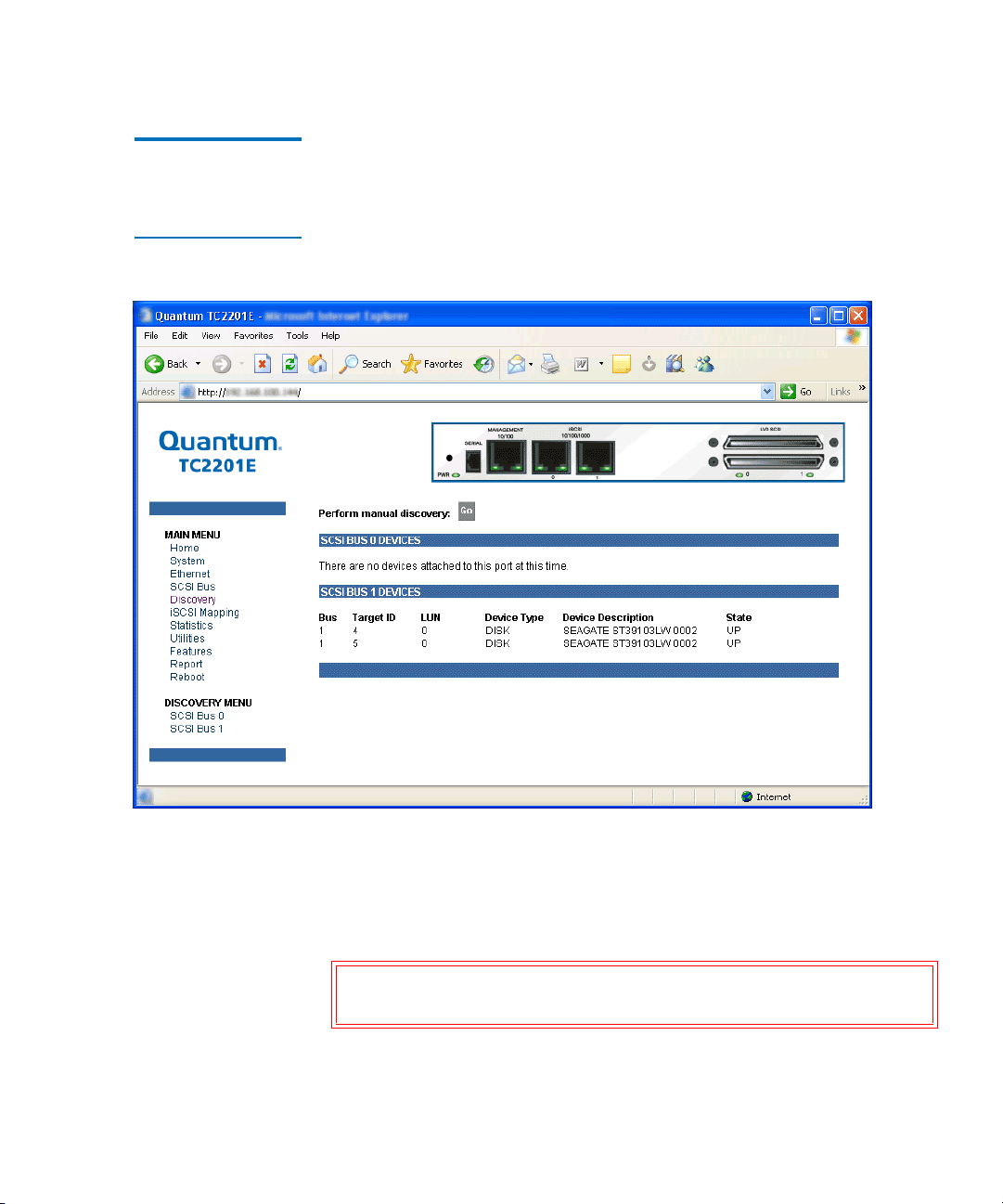
Chapter 3 Quantum Visual Manager
Main Menu
Main Menu > Discovery
Figure 41 Discovery
Page
This page shows currently known target devices and allows manual
discovery of new target devices.
3
From the Discovery Menu, select the SCSI bus to view/discover devices
specific to that bus. The Go button activates discovery for all the ports
and buses, or for just the selected port or bus. When the discovery process
is activated, it is performed according to the settings configured in the
iSCSI and SCSI configuration pages.
Caution: Discovery should not be used when SCSI command or
I/O operations are in progress.
Quantum TC2201E User’s Guide 61
Page 82
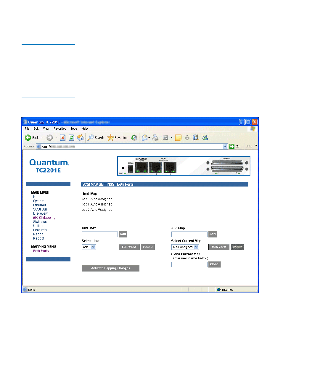
Chapter 3 Quantum Visual Manager
Main Menu
Main Menu > iSCSI Mapping
Figure 42 iSCSI
Mapping Page
This page shows all available iSCSI hosts with maps that have been
assigned to the current port. Maps and hosts may be added, edited, or
3
deleted. To choose a different port, select from the list of ports shown in
the menu under the heading Mapping Menu by left-clicking on the
desired port.
After the iSCSI port has been selected, mapping information for that port
is displayed including the name of the port, the currently selected host
and map. The following options are also available:
• Add a new host or map by selecting the respective Add button.
• Select an existing host or map from the pull-down lists for Select Host
and
Select Map.
62 Quantum TC2201E User’s Guide
Page 83

Chapter 3 Quantum Visual Manager
Main Menu
• Delete the currently selected host or map by selecting the respective
Delete button.
• View or Edit the currently selected host or map by selecting the
respective
Edit/View button.
• Clone (via the Clone Map button) the currently selected map and set
up the name of the new cloned map. This option makes it easier to
setup new maps with similar information to
previously created maps. Auto Assigned maps cannot be cloned.
• Select the Activate Mapping Changes button to dynamically update
the current map without rebooting the TC2201E. These changes are
made effective immediately after being submitted.
Caution: Before activating any port mapping changes, it is strongly
recommended that the user verify there are not any
command or data operations occurring in conjunction
with devices affected by the mapping changes. For
example, deleting a LUN or device from a map may
disrupt I/O transfers with that device. It is the user’s
responsibility to ensure that no operations will be
negatively impacted due to the activation of mapping
changes.
Note: All current Mapping Settings will take effect immediately! If
another management interface has made unsaved mapping
changes, those changes will be lost.
Note: If the
Activate Mapping Changes button is not selected, the
mapping changes will not take effect unless the TC2201E is
rebooted.
The following shows the select host page when the Select Host Edit/View
button is selected.
Quantum TC2201E User’s Guide 63
Page 84
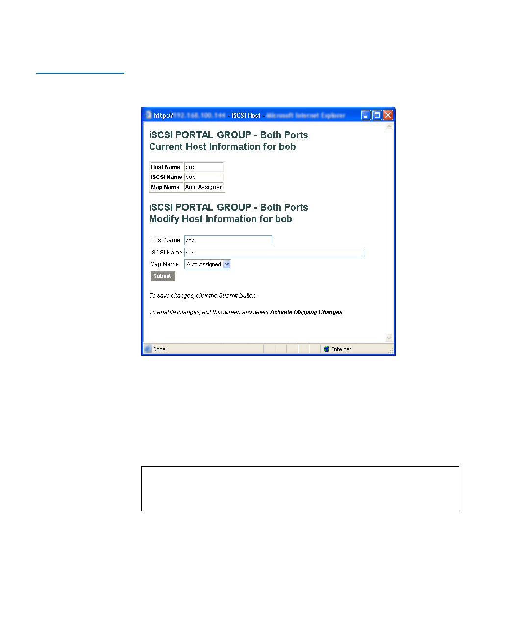
Chapter 3 Quantum Visual Manager
Main Menu
Figure 43 Select Host
Page
The current host information is shown at the top of the page. This
information can be changed in the Modify iSCSI Host section.
• New or updated information can be typed into the field boxes for
Host Name, iSCSI Name, and Map Name.
• The Map Name can be selected from the drop-down list.
• To make the changes permanent, select the Submit button.
Note: Host settings are saved to memory when the Submit button is
selected but are not activated until either the
Changes
button is selected or the TC2201E is rebooted.
The following shows the select current map page when the Select Current
Map
Edit/View button is selected.
64 Quantum TC2201E User’s Guide
Activate Mapping
Page 85
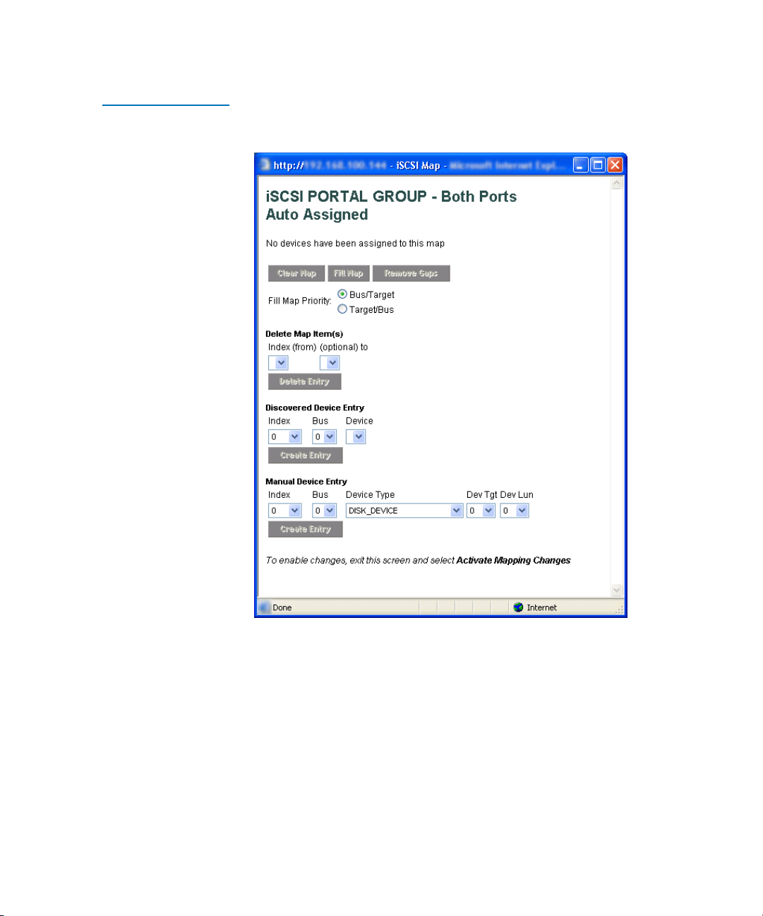
Figure 44 Select
Current Map Page
Chapter 3 Quantum Visual Manager
Main Menu
• To completely clear the current map of all entries, select the Clear Map
button.
• To fill the map, select the fill option from the pull-down list and then
select the
Fill Map button. When the map is filled, the menu shows the
current mappings.
Quantum TC2201E User’s Guide 65
Page 86

Chapter 3 Quantum Visual Manager
Main Menu
• To remove all gaps, or unfilled entries, from this map, select the
Remove Gaps button. When removing gaps from the table, this
option also renumbers all Indexes in sequential order starting with
Index 0.
Note: Some operating systems require gaps be removed in the
• To delete a specific map entry, select an Index from the pull-down list
under Delete Map Item. To delete multiple Indexes, also select the
end of the range from the optional pull-down list. Either way, select
the
• To create a specific map item, the Index, Bus, and Device can be
selected from the pull-down lists for either Discovered Device Entry
or Manual Device Entry. Discovered Device Entry is limited to
devices already discovered. Manual Device Entry allows you to
manually set up a device type at a specific Device Target and Device
LUN. To make the changes permanent, select the
mapping table in order to detect all devices.
Delete Entry button to remove the item(s) from the map.
Create Entry button.
Note: Maps named ‘Auto Assigned’ may not be modified, cleared,
filled, or have entries removed.
Note: Map settings are saved to memory when any of the buttons
within the page are selected but are not activated until either
the Activate Mapping Changes button is selected or the
TC2201E is rebooted.
66 Quantum TC2201E User’s Guide
Page 87
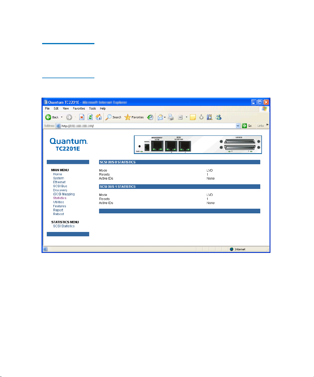
Chapter 3 Quantum Visual Manager
Main Menu
Main Menu >
Statistics 3
Figure 45 Statistics
Page
This page shows SCSI bus statistics.
Select SCSI Statistics from the Statistics Menu on the left and then select
the
Go button to clear all current statistics for the selected buses and
continue logging any new statistics.
Quantum TC2201E User’s Guide 67
Page 88
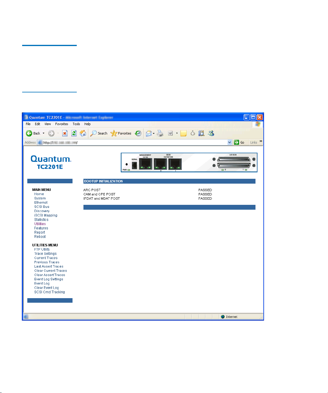
Chapter 3 Quantum Visual Manager
Main Menu
Main Menu > Utilities
Figure 46 Utilities
page
This page allows access to the FTP utility and the settings and
information for the event log and various trace options. Select from the
3
list of menu options shown under the heading Utilities by left-clicking on
the desired selection.
68 Quantum TC2201E User’s Guide
Page 89

Chapter 3 Quantum Visual Manager
Main Menu
Main Menu >
Utilities
> FTP
Utility
This page provides access to an FTP Utility.
3
Quantum TC2201E User’s Guide 69
Page 90

Chapter 3 Quantum Visual Manager
Main Menu
Figure 47 FTP utility
page
Note: Internet access is required to verify the signature for the FTP applet
and to download the JAVA applet plug-in for your browser.
The FTP Utility requires the use of a JAVA applet and will prompt for
permission to install the applet, if needed. If you receive this prompt,
70 Quantum TC2201E User’s Guide
Page 91

Chapter 3 Quantum Visual Manager
Main Menu
follow the on screen instructions to complete installation of the applet.
The FTP Utility then prompts for permission to run the applet.
To proceed, select the Grant this session button so the FTP Utility
becomes available for use.
To use the FTP Utility, do the following:
1 1. Fill in the User Name, Password, and IP Address of the TC2201E.
2 2. Select the Connect button to establish an FTP session with the
TC2201E.
3 3. Select a local file to upload or download. The following file types
are supported.
For uploads, or files sent to the TC2201E, you can select from .cfg
(configuration files) and .dlx (firmware files) formats.
For Downloads, or files retrieved from the TC2201E, you can select from
.cfg (configuration files) as well as from either curtrace.txt (system traces
for current boot cycle) or prvtrace.txt (system traces from previous boot
cycle).
4 Select binary transfer mode for the TC2201E.
5 5. Select the Put to Rtr button to upload a file to the TC2201E or the
Get From Rtr button to download a file from the TC2201E.
If a valid firmware or configuration file is sent to the TC2201E, an
automatic reboot will occur once the file has been received by the
TC2201E. The user will not be able to access the TC2201E from the Visual
Manager web interface during the time that the reboot is in process,
usually a period of about 2 minutes.
Quantum TC2201E User’s Guide 71
Page 92

Chapter 3 Quantum Visual Manager
Main Menu
Main Menu >
Utilities
> Trace
Settings
Figure 48 Trace
settings page
This page allows the configuration of trace settings.
3
Select the Submit button to submit changes for the Basic Trace Settings
Page, for trace logging of the TC2201E.
Select the Advanced Button to open the Advanced Trace Settings Page,
which appears similar to the Basic Trace Settings Page but offers an
expanded view with more trace options.
72 Quantum TC2201E User’s Guide
Page 93

Figure 49 Advanced
trace settings page
Chapter 3 Quantum Visual Manager
Main Menu
For both the Basic and Advanced pages, the default setting for each trace
setting is Min (track non-error conditions) but any or all settings can be
changed to Errs (track error conditions) or All (track both error and non-
Quantum TC2201E User’s Guide 73
Page 94

Chapter 3 Quantum Visual Manager
Main Menu
error conditions) or to advanced trace level settings located between
these.
Note: These settings are normally used for diagnostic purposes as
Main Menu >
Utilities
TracesPrevious
TracesLast Assert
Traces
> Current
The Current Traces, Previous Traces, and Last Assert Traces menu
options show the indicated trace information. Current Traces shows data
since the TC2201E was last booted. Previous Traces shows data from the
last boot cycle. Last Assert Traces shows data from the last assertion.
3
directed by an authorized Quantum service technician. Using
these settings during normal operations can result in
performance degradation of the TC2201E.
74 Quantum TC2201E User’s Guide
Page 95

Figure 50 Current
TracesPage
Chapter 3 Quantum Visual Manager
Main Menu
Trace buffers can be cleared by selecting either the Clear Current Traces
option or the
Clear Assert Traces option.
Quantum TC2201E User’s Guide 75
Page 96
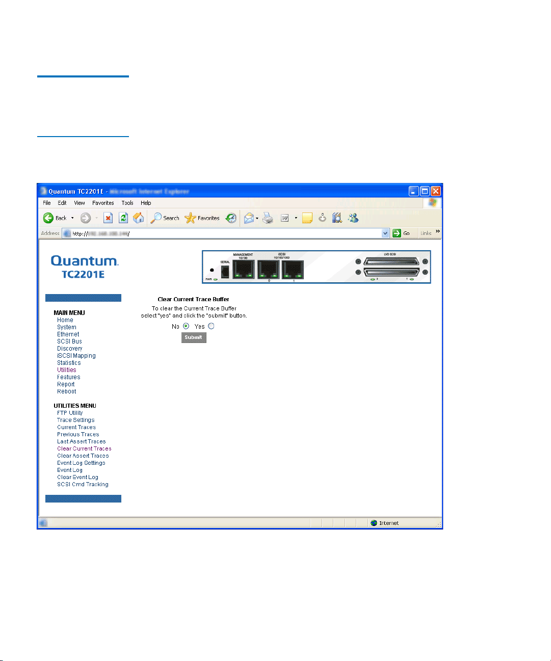
Chapter 3 Quantum Visual Manager
Main Menu
Main Menu >
Utilities
> Clear
Current Traces
Figure 51 Clear
Current Trace Buffer
Page
This page allows the current trace buffer to be cleared.
3
When this option is selected, a confirmation message will appear to verify
the selection. If a response of Yes is given to the confirmation message,
the unit will clear the current trace buffer. Current TC2201E activities will
not be disrupted by this operation. Select the
your choice.
76 Quantum TC2201E User’s Guide
Submit button to finalize
Page 97
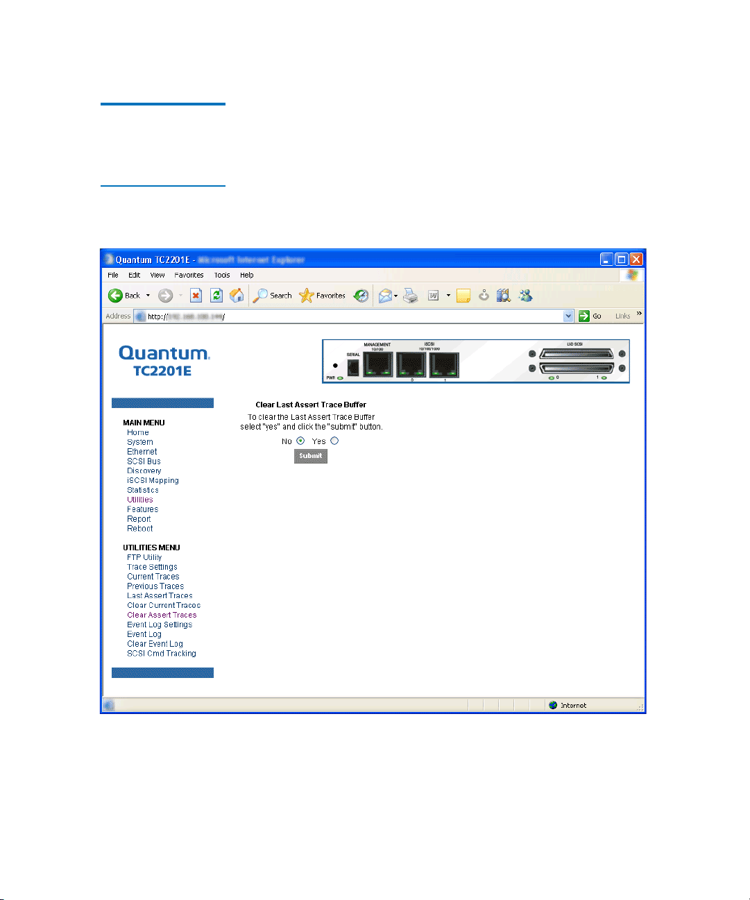
Chapter 3 Quantum Visual Manager
Main Menu
Main Menu >
Utilities
> Clear
Assert Traces
Figure 52 Clear
Assertion Trace Buffer
Page
This page allows the assert trace buffer to be cleared.
3
When this option is selected, a confirmation message will appear to verify
the selection. If a response of Yes is given to the confirmation message,
the unit will clear the assert trace buffer. Current TC2201E activities will
not be disrupted by this operation. Select the
Submit button to finalize
your choice.
Quantum TC2201E User’s Guide 77
Page 98
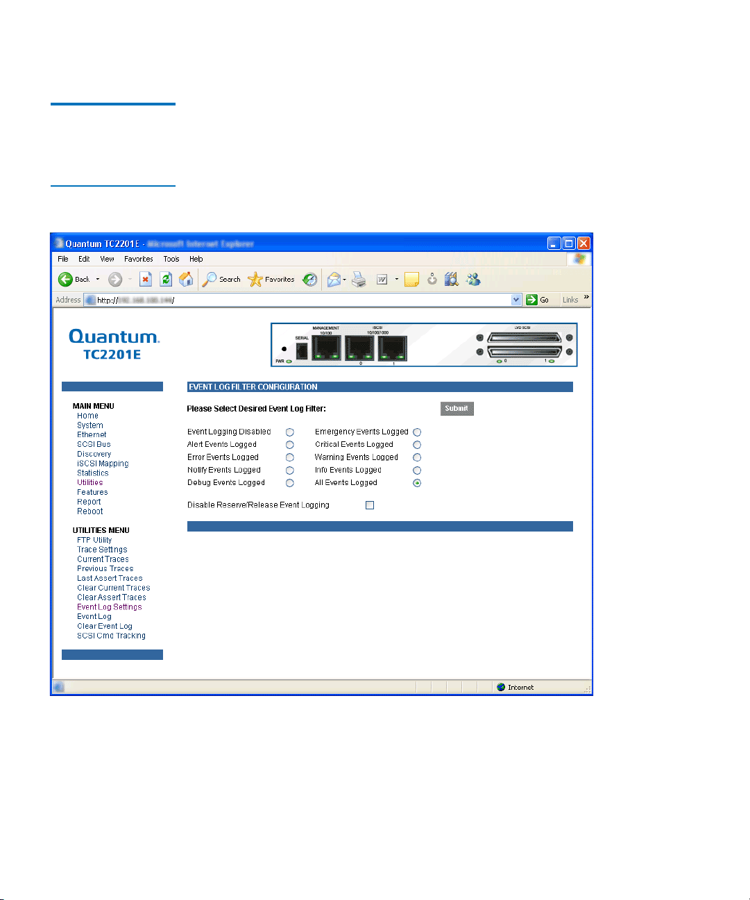
Chapter 3 Quantum Visual Manager
Main Menu
Main Menu >
Utilities
> Event
Log Settings
Figure 53 Event Log
Settings Page
This page allows set up of Event Log Settings.
3
To make any changes, modify the entries as described below and then
select the
Submit button.
Select from the Event Log settings shown. Each option enables/disables
its respective filtering option. Event logging captures over 2000 events
78 Quantum TC2201E User’s Guide
Page 99

Chapter 3 Quantum Visual Manager
Main Menu
and then starts overwriting the log when full. The default setting is All
Events Logged.
Note: So that event logging is accurate, be sure to correctly set the
clock and date in the Real Time Clock Configuration menu.
Quantum TC2201E User’s Guide 79
Page 100
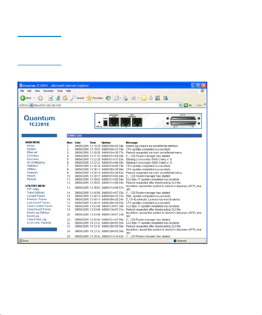
Chapter 3 Quantum Visual Manager
Main Menu
Main Menu >
Utilities
> Event
Log
Figure 54 Display
Event Log Page
This page displays the Event Log.
3
80 Quantum TC2201E User’s Guide
 Loading...